Note: Descriptions are shown in the official language in which they were submitted.
CA 03093434 2020-09-08
WO 2019/173601 PCT/US2019/021167
ATNZ200127W 001
ENHANCED SAFETY AND RELIABILITY FOR A NETWORKED DETONATOR
BLASTING SYSTEM
REFERENCE TO RELATED APPLICATION
Under 35 U.S.C. 119, this application claims priority to, and the benefit of,
U.S.
provisional patent application number 62/639,668, entitled "ENHANCED SAFETY
AND
RELIABILITY FOR A NETWORKED DETONATOR BLASTING SYSTEM", and filed on
March 7, 2018, the entirety of which is hereby incorporated by reference.
TECHNICAL FIELD
The present disclosure relates to blasting networked systems for electronic
detonators.
BACKGROUND
In blasting operations, detonators and explosives are buried in the ground,
for
example, in holes (e.g., bore holes) drilled into rock formations, etc., and
the detonators are
wired for external access to blasting machines that provide electrical
signaling to initiate
detonation of explosives. Electronic detonators can implement programmable
delay times
such that an array of detonators can be actuated in a controlled sequence. The
blasting
machine is normally turned on and a blast sequence includes power up,
verification and/or
programming of delay times, arming and finally issuance of a "fire" command.
The blasting
machine provides sufficient energy and voltage to charge the firing capacitors
in the
detonators, and initiates the actual detonator firing in response to the fire
command. During
the firing phase, the blasting machine fires the detonator array.
SUMMARY
Various aspects of the present disclosure are now summarized to facilitate a
basic
understanding of the disclosure, wherein this summary is not an extensive
overview of the
disclosure, and is intended neither to identify certain elements of the
disclosure, nor to
delineate the scope thereof. Instead, the primary purpose of this summary is
to present some
concepts of the disclosure in a simplified form prior to the more detailed
description that is
- 1 -
CA 03093434 2020-09-08
WO 2019/173601 PCT/US2019/021167
ATNZ200127W 001
presented hereinafter. Disclosed examples include apparatus and techniques for
remote turn
on of the blasting machine and reliable fire and arm commands issuance.
BRIEF DESCRIPTION OF THE DRAWINGS
The following description and drawings set forth certain illustrative
implementations
of the disclosure in detail, which are indicative of several exemplary ways in
which the
various principles of the disclosure may be carried out. The illustrated
examples, however,
are not exhaustive of the many possible embodiments of the disclosure. Other
objects,
advantages and novel features of the disclosure will be set forth in the
following detailed
description of the disclosure when considered in conjunction with the
drawings, in which:
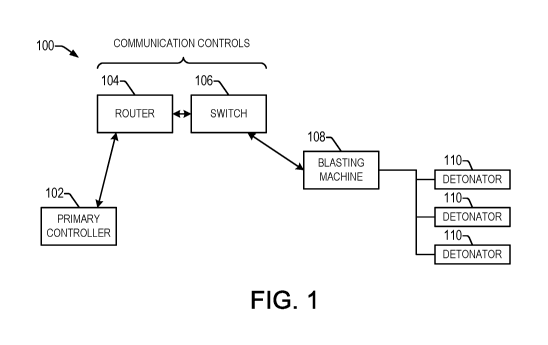
FIG. 1 is a block diagram of a networked electronic blasting system.
FIG. 2 is a block diagram of a networked electronic blasting system.
FIG. 3 is a flow diagram of a fire command issuance by a primary device to a
blasting
machine.
FIG. 4 is a diagram of a PC software to control the blasting machine using
Ethernet
protocol.
FIG. 5 is a simplified system diagram illustrating a wireless blasting system
for
remotely firing an array of detonators connected to a blasting machine at a
blast site,
including a remotely located wireless master controller and a wireless slave
bridge unit
connected to the blasting machine in accordance with one or more aspects of
the present
disclosure;
FIGS. 6 and 7 are schematic diagrams illustrating first and second embodiments
of
the remote turn on and remote turn off features of the blasting machine and
slave bridge unit;
FIGS. 8A-8C provide a flow diagram illustrating an exemplary process for
operating
the slave bridge unit;
FIG. 9 is a signal flow diagram illustrating operation of the master
controller, slave
bridge unit and blasting machine in the system of FIG. 1;
FIGS. 10A-10B provide a flow diagram illustrating an exemplary process for
operating the blasting machine;
- 2 -
CA 03093434 2020-09-08
WO 2019/173601 PCT/US2019/021167
ATNZ200127W 001
FIG. 11 is a simplified system diagram illustrating an alternate wireless
blasting
system with a wireless slave blasting machine in accordance with further
aspects of the
present disclosure; and
FIG. 12 is a flow diagram illustrating a data designation process to prevent
remote
.. out-of-sync conditions between the blasting machine and the remote master
controller.
DETAILED DESCRIPTION
Referring now to the figures, several embodiments or implementations of the
present
disclosure are hereinafter described in conjunction with the drawings, wherein
like reference
numerals are used to refer to like elements throughout, and wherein the
various features are
not necessarily drawn to scale.
FIG. 1 shows an example networked blasting system 100 for electronic
detonators
110, which can be used in a variety of applications, for example, in
underground mines. The,
.. system 100 includes a primary controller 102 (e.g., an Ethernet
controller), a communication
device formed by a router 104 and a switch 106 that is connected to an
Ethernet compatible
blasting machine 108. The Ethernet blasting machine 108 is wired to an array
of detonators
110 in a blasting array. The network system 100 uses digital communication bus
protocols
e.g., Ethernet, CAN, RS-232, RS-422 or RS-485. The primary controller 102 is
configured
to communicate via any suitable general network or connection (e.g., WiFi,
UHF, USB,
optical fiber, etc.) With such configuration no extra long leadline is needed
to connect the
primary controller to the array of detonators. Maximum range is determined
from the length
and type (i.e. copper or fiber optic) of the established network lines laid
out in the mines, for
example, from 1 ¨5 miles away. Additionally the primary controller 102 can be
positioned
.. more flexibly anywhere, and there are no limitations as to where the
primary controller 102 is
laid out in the wired networked system 100.
In such a blasting system 100, the blasting machine 108 is connected but not
energized until remotely commanded via primary controller together with the
communication
controller 104, 106 as the operator walks from the blast area to the primary
controller site
.. some distance away. The blast sequence includes power up, verify and/or
program the delay
- 3 -
CA 03093434 2020-09-08
WO 2019/173601 PCT/US2019/021167
ATNZ200127W 001
times, arming and finally the fire command. The blasting machine 108 contains
sufficient
energy, voltage to charge the firing capacitors in the electronic detonators
110.
In the arm stage, a command is issued to all the detonators 110 to charge the
firing
capacitors in the electronic detonators 110.
During the firing phase, upon a blaster' s input, a fire command is
transferred from the
primary 102 through the communication controls 104, 106, which then issues the
final fire
command to fire the entire array of detonators 110. In some systems, only a
single fire
command is transmitted to the blasting machine 108 from the primary controller
102 to
initiate the final blasting of the array of detonators 110. In certain
examples in the illustrated
system 100, the primary 102 issues first and second fire commands, with
corresponding CRC
checks and a timeout check in order to facilitate safe operation of the system
100, as seen
further below in FIG. 3.
Because the arm and fire commands involve the energization and firing of the
electronic detonators 110, disclosed examples provide a reliable and safe
method to facilitate
.. proper receipt and action in response to the commands.
Disclosed examples provide enhanced safety of a networked electronic detonator
blasting system 100 by using a remote turn on of the blasting machine 108 and
a more
reliable fire and arm commands issuance. By having the remote turn on, the
blasting
machine is not powered up even though the branchlines or leadline are
connected with the
array of detonators 110. Rather, the blasting machine 108 is only turned on
when the unit
establishes a link to the primary controller 102, and the blasting machine is
enabled by the
primary controller 102. A second or more of the arm/ fire commands issued by
the primary
controller 102 are used in certain examples to ensure that it is a valid
command to arm/fire
and to diminish any inadvertent perception of an arm/fire command.
When the leadline is connected to the blasting machine 108, the blasting
machine 108
does not energize the bus lines connected to the blasting array of detonators
110, even though
it is connected to the network. Therefore the array of detonators 110 on the
entire bus is not
electrically connected to any live or powered bus line. The blasting machine
108 in one
example implements a remote turn on feature, upon the proper turn on command
from the
- 4 -
CA 03093434 2020-09-08
WO 2019/173601 PCT/US2019/021167
ATNZ200127W 001
Ethernet controller (e.g., primary 102), and in response, applies power to the
bus line
containing the electronic detonators 110.
In one example, successful reception of multiple fire or arm commands from the
primary 102 to the blasting machine 108 is used by firmware of one or more
microcontrollers
in the blasting machine 108 as a gating condition to be interpreted as a valid
fire or arm
command. Absent this advantageous feature, even with a CRC check at the end of
the
received serial Ethernet packet, there is a finite possibility of a command
other than a fire or
arm being construed as an unintended fire or arm command, e.g., simultaneous
bit flips in
both the command bytes and CRC. Therefore the reliability and safety of a fire
or arm
command is significantly enhanced by having valid reception of multiple fire
or arm
commands plus acknowledgements for each fire or arm command issuance. The
likelihood
of bit flips of 2 or more sequential commands within the timeout period is
extremely low
especially with acknowledgement after each fire or arm command.
FIG. 1 shows an Ethernet enabled electronic detonator blasting system 100.
Other
digital communication bus protocols can be utilized, e.g. CAN, RS-232, RS485,
or RS422 in
the network. The controller 102 communicates 2-way with the blasting machine
108, in this
example, via the router 104 and the switch 106. The primary controller 102
essentially
controls the operation of the blasting machine 108 remotely. In one example,
all functions,
status, and messages are displayed or echoed on the primary controller display
screen 102, to
enable the operator of the primary controller 102 to see whatever is on the
blasting machine
display safely at a considerable distance away. In one example, the blasting
system includes
multiple Ethernet addressable switches configured to selectively turn off or
on selected
branch lines to a main leadline during logging or blasting operation. In one
example, the
blasting system includes one or more security keys that must be entered or
inserted in order
to enable the blasting system and communicate with an array of the detonators.
Individual
and separate security keys are required in one example to initiate
communication, charge and
fire a network of detonators.
FIG. 2 is a block diagram of another example networked electronic blasting
system
200, including a PC-based primary controller 202, along with a router 104, a
switch 106, and
a blasting machine 108 as described above. In this example, the primary
controller 202
- 5 -
CA 03093434 2020-09-08
WO 2019/173601 PCT/US2019/021167
ATNZ200127W 001
includes a blasting machine equipped with an Ethernet controller, or PC
software with
Ethernet capability. The primary 202 in this case is implemented using the PC
software, and
the primary 202 communicates through the Ethernet network to the blasting
machine 108,
which in turn is connected to the array of electronic detonators via a
leadline (not shown in
FIG. 2).
FIG. 3 is a flow diagram of a process 300 including a fire command issuance by
a
primary device 102, 202 to a secondary blasting machine 108. During a fire
command phase,
upon detection of a valid fire command issued by the primary 102 (302 in FIG.
3), the
blasting machine 108 checks for any CRC errors at 304, and invalidates the
fire command at
306 if any CRC error is detected. If there are no CRC errors at 304, the
blasting machine 108
sends an acknowledgment to the primary device 102, 202 at 308 to acknowledge
safe receipt
of the first fire command. If the controller 102, 202 does not receive an
acknowledgment
within a predetermined time, a timeout error is processed at 310, and the fire
command is
invalidated at 306. If the controller 102, 202 receives the expected
acknowledgment at 308
before the timeout period has expired (NO at 310), the primary controller 102
sends a second
fire command to the blasting machine 108 at 312 in FIG. 3. In one example, the
blasting
machine 108 implements a second timeout check, beyond which if there is no
second or
further fire commands, this will be treated as an invalid fire command or an
automatic abort
and therefore the fire command is not enabled or accepted by the blasting
machine 108.
.. Continuing in the example of FIG. 3, the blasting machine 108 performs a
CRC error check
at 314 on the received second fire command, and if any CRC errors are detected
(YES at
314), the fire command is invalidated at 306. If no CRC errors are detected in
the second fire
command (NO at 314), the blasting machine 108 sends the fire command to the
detonators
110 at 314 to complete the firing process 300.
FIG. 4 illustrates an example display screen of a PC-based software
implementation
of the primary controller 102.
In one example of a blast using an Ethernet enabled electronic blasting system
to
initiate the firing, the following operations are present:
- 6 -
CA 03093434 2020-09-08
WO 2019/173601 PCT/US2019/021167
ATNZ200127W 001
a) The electronic detonators are appropriately programmed and logged using
a
logger or set of loggers. The delay times may be programmed during the logging
process or
they may been pre-programmed previously.
b) The detonators are then connected to each of their individual branch
wires.
c) The logger
is used to verify that each and every detonator in the specific
branch are all present and accounted for to ensure electrical connection.
d) The detonator data are transferred to the blasting machine.
e) The branches wires are next connected to the leadline wire.
0 The blast area is now cleared to personnel and/or equipment.
g) The leadline goes to the blasting machine some distance away.
h) The blasting machine is not powered up at all thus no power, current or
voltage is present on the leadline all the way to the array of detonators.
i) At the blasting site, the PC software is executed. An Ethernet
communication
link is established between the PC and the selected blasting machine with the
appropriate
Ethernet address and protocol. Once the link is established, the powered is
applied to the
blasting machine.
I)
The user will use the PC to issue commands such as verify and charge the
detonators. These commands are relayed to the blasting machine to verify and
to arm the
electronic detonators in the entire array. During the verify phase, any
missing detonators will
be flagged. During the arming phase, the firing capacitors in the electronic
detonators are
charged up. Calibration is also performed during this phase. Any error in the
blasting
machine will be echoed back to the remote display; thus the user has instant
access and
control over the entire blast process.
k)
Finally, when ready for the firing phase, the fire button(s) ¨ a sequence of
fire
and arm button press for redundant safety) is pressed, the PC sends the fire
command to the
blasting machine. It is acknowledged and the PC then sends another fire
command as a
confirmation to the blasting machine within a specific time period.
Subsequently the blasting
machine will then issue the digital encoding for the fire signal to the array
of detonators.
1)
After the fire phase, power is then turned off to the blasting machine by the
PC.
- 7 -
CA 03093434 2020-09-08
WO 2019/173601 PCT/US2019/021167
ATNZ200127W 001
In another example implementation, the multiple arm/fire command scan also be
sent
to the blasting machine 108 without any acknowledgement by the blasting
machine 108 back
to the bridge or primary controller 102, 202 for the successive arm/fire
commands to follow.
In one example, the fire commands can be sent within a spaced timeout which
the blasting
machine 108 expects to receive in a row before a valid signal to arm/fire is
interpreted.
In case of any Ethernet communications breakdown, the slave blasting machine
108
will revert to a safe state, namely discharge and shut down the bus line after
a predetermined
time of no communications from the primary controller 102, 202.
For multiple secondary blasting machines 108, the system 100,200 can
accommodate
synchronize firing of all the detonators 110 (e.g., with or without any
programmed delay
times). In one example, the primary controller 102, 202 sends broadcast fire
commands to
the addressed secondary devices (e.g., secondary blasting machines 108) on the
Ethernet
network via the router 104 and switch 106, or multiple routers and/or
switches, to ensure that
the multiplicity of secondary blasting machines 108 receive and act on the
fire commands
with the same time reference. In one example, no acknowledgments are issued to
avoid any
contention if the secondary is responding back individually to the fire
command received,
although not a strict requirement of all possible implementations.
Added software safety controls in various examples include: (1) an automated
countdown timer implemented by the blasting machine 108 which will shut down
the
blasting machine 108 if no operator command activity is detected for a
predetermined time
period, such as for 30 minutes. Example software safety controls also include
(2) an
automated countdown timer that only allows the blasting machine 108 to hold
the detonators
110 in a charged state with no command activity for 10 minutes. In one
example, in order to
simulate the arm and fire buttons being held simultaneously for sending the
fire command, a
countdown timer method is used, including:
After detonators are charged and ready to fire:
Operator presses the arm button,
Countdown timer starts at 5 seconds - allowing operator to press the fire
button to
send the fire command,
- 8 -
CA 03093434 2020-09-08
WO 2019/173601 PCT/US2019/021167
ATNZ200127W 001
If the fire button is pressed before the countdown timer reaches 0, the fire
commands
will be initiated,
If the countdown timer goes to 0 before the fire button is pressed, the
software
application will abort the fire attempt, and continue to hold in a charged
state. The operator
must re-start the arm and fire sequence again, and
Once the fire command is send and acknowledgement received, the application
will
automatically turn off the blasting machine within 30 seconds of the fire
command being
sent.
In one example, the Ethernet blasting machine 108 is configured to turn off in
30
minutes or another predetermined or set time, if no Ethernet communication
detected, as a
fail safe measure. In one example, when initiating a blast, the primary
controller 102 sends
multiple Ethernet fire commands via Ethernet packages with necessary
acknowledgements,
for example, at least two such pairings of fire commands and acknowledgments
from the
Ethernet blasting machine 108, with a predetermined time window of acceptable
acknowledgement after validated reception of one such fire command. In one
example, the
system includes a protected Ethernet connection box operatively coupled in one
or more of
the connection paths between the primary controller 102 and the blasting
machine 108,
including clamping elements such as Zeners, TVS or SCRs to avoid damage to the
entire
Ethernet network and to protect the network elements (e.g., the controller
102, the router 104,
the switch 106 and/or the blasting machine 108) against electrical after
effects (e,g. plasma
and/or high voltage EM fields) associated with a blast or detonation. In
certain examples, for
synchronized firing of multiple blasting machines 108, each with its own
unique Ethernet
address, the primary controller 102 issues at least 2 broadcast fire commands
with different
pre-countdown times to the delay time, and each Ethernet blasting machine 108
is configured
to acknowledge reception of the fire commands to the primary controller 102.
In one
example, if one or more of the blasting machines 108 does not properly
acknowledge the fire
command, the primary controller 102 implements a last minute abort of the
firing, such as a
voltage check at time T=0 before commencement of final delay countdown, or a
discharge
command to all the blasting machines 108.
- 9 -
CA 03093434 2020-09-08
WO 2019/173601 PCT/US2019/021167
ATNZ200127W 001
Certain examples tailor fundamental wireless functionalities to operate within
the
Ethernet framework to network control an electronic blasting system. Suitable
examples of
wireless blasting apparatus and methods are described below. Although the
following
description and drawings show wireless network connections, wired connections
can be used
instead, or in combination with wireless connections in various
implementations. In one
example implementation, the blasting machine 402 corresponds to the blasting
machine 108
of FIG. 1 above, the slave bridge unit 420 corresponds to one or both of the
ethernet router
104 and/or the ethernet switch 106 (e.g., the COMMUNICATION CONTROLS) in FIG.
1,
and the master controller 440 corresponds to the primary controller 102 of
FIG. 1. Although
described hereinafter in the context of wireless communications
interconnections between
network elements, wired connections are possible alone or in combination with
wireless
connections, using ethernet or other communications protocol and devices.
FIG. 5 shows a wireless blasting system with a blasting machine 402 is a
wireless-
enabled slave bridge unit 420 located at or near a blast site B that includes
a detonator array
A with a number of electronic detonators D connected by wires to a single pair
of lead lines
LL. As shown in FIG. 5, the lead lines LL are connected to a firing circuit
404 of the blasting
machine 402, although various operational aspects of the disclosed methods and
systems
contemplate that the lead lines LL may be connected to the firing circuit 404
only at certain
points in a blasting process. A key 403 may be associated with the blasting
machine 402 for
security purposes, for example, to ensure that the blasting machine 402
operates only once a
proper key 403 is installed. In other embodiments, password protection may be
provided in
the blasting machine 402, requiring an operator to enter a proper password to
enable blasting
machine operation, and the key 403 may be omitted. The blasting machine 402
further
includes a microprocessor and associated electronic memory 406 operatively
connected to
the firing circuit 404 and to a communications interface 408. As is known, the
blasting
machine 402 may be housed in a suitable environmental enclosure capable of
withstanding
the rigors and environmental conditions of blasting sites, and the blasting
machine 402 in
certain implementations includes an internal battery 410 for operation without
requiring
connection of external power lines. Other embodiments are possible in which
the blasting
- 10 -
CA 03093434 2020-09-08
WO 2019/173601 PCT/US2019/021167
ATNZ200127W 001
machine 402 does not include an internal power source, and operates
exclusively using
power supplied from a connected slave bridge unit 420.
The slave bridge unit 420 is really housed in a suitable enclosure and
operated by a
battery 430, and may have an associated key 423 for operating the unit 420.
The slave bridge
unit 420 may alternatively or in combination be password-protected, requiring
user entry of a
password to enable bridge unit operation, and the key 423 may be omitted. One
or both of
the blasting machine 402 and the slave bridge unit 420 may also include
various user
interface features (not shown) allowing an operator to perform various
operations by pressing
buttons, and may provide a display screen or other output means by which an
operator can
receive data or messages. The slave bridge unit 420 includes a communications
interface
428 allowing communication between the slave bridge unit 420 and the blasting
machine 421
connected by a communications cable 412. In addition, the slave bridge unit
420 includes a
microprocessor and associated electronic memory 426 that is operatively
connected to the
communications interface 428 as well as to a wireless transceiver 422 having
an associated
RF antenna 432. Moreover, the illustrated bridge unit 420 includes a power
control circuit
424 operative to selectively enable or disable the firing circuit 404 of the
blasting machine
402 by any suitable means, including without limitation provision of firing
circuit power 414
and/or by providing a power gating control signal 414, 414a in order to
control the provision
of power to the firing circuit 404, examples of which are further illustrated
in FIGS. 6 and 7.
Also, the slave bridge unit 420 includes an internal battery 430 allowing
field operation.
The processors 406, 426 may be any suitable electronic processing device
including
without limitation a microprocessor, microcontroller, DSP, programmable logic,
etc. and/or
combinations thereof, which performs various operations by executing program
code such as
software, firmware, microcode, etc. The devices 402, 420 each include an
electronic
memory operatively associated with the corresponding processors 406, 426 to
store program
code and/or data, including computer executable instructions and data to
perform the various
functionality associated with blasting machine operation as is known as well
as
communications tasks and the various function set forth herein. The memory of
the devices
402, 420 may be any suitable form of electronic memory, including without
limitation RAM,
EEPROM, flash, SD, a multimedia card, etc.
- 11 -
CA 03093434 2020-09-08
WO 2019/173601 PCT/US2019/021167
ATNZ200127W 001
As further shown in FIG. 5, a master controller apparatus 440 includes a
microprocessor and electronic memory 446 operatively coupled with a user
interface 444 and
a wireless transceiver 442 with an associated RF antenna 448. In operation,
the master
controller 440 and the slave bridge unit 420 establish a radio-frequency (RF)
or other
wireless communications link 434 via the transceivers 442, 422 and the
corresponding
antennas 448, 432, thus allowing the master controller 442 operate the slave
bridge unit 420
and hence the blasting machine 402 at a significant distance away from the
blast site 408,
such as several miles in certain implementations. In this manner, the remote
positioning of
the master controller 440 facilitates operator safety during blasting
operations, with the
various concepts of the present disclosure further facilitating operator
safety as detailed
further below.
FIG. 6 illustrates one possible implementation of the blasting machine 402 and
the
slave bridge unit 420 facilitating control of the application of electrical
power to the blasting
machine firing circuit 404 by the slave bridge unit 420. In various
situations, the disclosed
blasting machine 402 and bridge apparatus 420 advantageously allow remote turn
on and/or
remote turn off of the firing circuit power, thereby enhancing personal safety
for blasting
sites. In this implementation, a relay 416 is provided in the blasting machine
420 for
selectively connecting power from the blasting machine battery 410 to the
firing circuit 404
according to a switching control signal 414 provided by the power control
circuit 424 of the
slave bridge unit 420. The control signal 414 can be provided from the bridge
unit 422 the
blasting machine 402 by a variety of means, including a dedicated control line
in a
communications cable 412, 414 connecting the units 420 and 402. In another
possible
embodiment, the power control circuit 424 is implemented in programming of the
processor
426, with the processor 426 providing a command message via the communications
interfaces 428, 408, with the blasting machine processor 406 controlling
operation of the
relay 416 accordingly, wherein the switching control signaling 414 is provided
via such
messaging between the units 420, 402. Other possible implementations may be
used by
which the slave bridge unit 420 selectively controls the application of power
to, or removal
of power from, the firing circuit 404 to selectively enable or disable the
firing circuit 404 of
the blasting machine 402. In this manner, the power control circuit 424
operates under
- 12 -
CA 03093434 2020-09-08
WO 2019/173601 PCT/US2019/021167
ATNZ200127W 001
control of the slave bridge unit processor 426 to selectively provide the
control signal 414 to
either apply power to the blasting machine firing circuit 404 or to ensure
that the firing
circuit 404 is unpowered.
FIG. 7 illustrates another non-limiting embodiment in which a dedicated power
line is
provided in cabling connecting the blasting machine 402 with the bridge unit
420, including
a single wire or pair of wires 414, where a single cable may also include the
communications
line or lines 412, or separate cabling can be provided. The slave bridge unit
420 in FIG. 7
includes an on-board relay 418 operative to selectively apply power from the
bridge unit
battery 430 to the firing circuit 404 of the blasting machine 402 according to
a switching
control signal 414a from the power control circuit 424. As in the
implementation of FIG. 6,
the power control circuit 424 may be a separate circuit operated under control
of the bridge
unit processor 426, or may be implemented via programming of the processor 426
to
selectively provide the switching control signal 414a to operate the relay 418
to thereby
selectively apply power from the battery 430 to the firing circuit 404, or to
ensure that the
firing circuit 404 is unpowered according to the state of the switching
control signal 414a.
In the illustrated implementations, a single contact relay 416, 418 may be
used, for
example, to connect a positive DC power line to the firing circuit 404, or a
relay 416, 418
may be used having multiple contacts, for instance, to selectively connect or
disconnect
multiple power lines to or from the firing circuit 404. In one possible
implementation, the
bridge unit processor 426 performs remote turn on of the firing circuit power
by asserting the
control signal 414 after connection of the bridge unit 422 the blasting
machine 402 only after
a verified communications link 434 is established between the master control
unit 440 and
the slave bridge unit 420. In another possible implementation, the processor
426 of the
bridge unit 420 is programmed to enable the firing circuit 404 via the power
control circuit
424 and the signaling 414, 414a only upon receipt of a command message from
the master
controller 440 instructing the bridge unit 420 to apply power to the firing
circuit 404. This
operation advantageously allows blasting operators to leave the blasting site
B before any
powered circuit is connected to the detonators D. In addition, the provision
of the power
control circuitry 424 and selective enabling/disabling of the firing circuit
404 by the slave
bridge unit 420 also facilitates remote turn off, whereby the slave bridge
unit processor 426 is
- 13 -
CA 03093434 2020-09-08
WO 2019/173601 PCT/US2019/021167
ATNZ200127W 001
programmed in certain embodiments to remove power from the firing circuit 404
via the
control signaling or messaging 414, 414a if the wireless link 434 between the
slave bridge
unit 420 and the master controller 440 is lost or if the master controller 440
sends a message
via the wireless link 434 to the bridge unit 420 with a command to turn off
power to the
firing circuit 404.
Referring again to FIG. 5, the master controller 440 and the slave bridge unit
420
implement two-way communications via the wireless link 434, by which the
master
controller 440 remotely controls the operation of the blasting machine 402
with all blasting
machine functions and messages being displayed or echoed on the user interface
444 of the
master controller 440. In this regard, the blasting machine 402 may have a
local user
interface (not shown), and may be operable in a local control mode according
to a keypad
and other means for receiving user inputs locally, with connection to the
slave bridge unit
420 placing the blasting machine 402 into a remote control mode for operation
according to
the master controller 440 via the wireless link 434 and the connection to the
slave bridge unit
420. In certain embodiments, echoing of the local blasting machine user
interface prompts
and displayed information via the bridge unit 420 to the master controller 440
enables the
remote operator at the master controller 440 to safely see remotely whatever
is on the
blasting machine display from a distance. In addition, the system implemented
by the
interconnection and operation of the master controller 440, the bridge unit
420 and the
blasting machine 402 performs various operations using multiple messages with
acknowledgment and verification as detailed below in order to further
facilitate safe and
predictable operation of a remote wireless blasting system.
Referring now to FIGS. 8A-10B, exemplary methods 150, 600 are illustrated for
implementing a remote wireless blasting operation, including a method 500 in
FIGS. 8A-8C
showing exemplary operation of the slave bridge unit 420, and a method 600 in
FIGS. 10A
and 10B for operating the blasting machine 402, along with a signal flow
diagram 550 in
FIG. 9 showing various interconnections and messaging between the master
controller 440,
slave bridge unit 420, blasting machine 402 and detonator array A. While the
exemplary
methods 500 and 600 are illustrated and described hereinafter in the form of a
series of acts
or events, it will be appreciated that the various methods of the disclosure
are not limited by
- 14 -
CA 03093434 2020-09-08
WO 2019/173601 PCT/US2019/021167
ATNZ200127W 001
the illustrated ordering of such acts or events. In this regard, except as
specifically provided
hereinafter, some acts or events may occur in different order and/or
concurrently with other
acts or events apart from those illustrated and described herein in accordance
with the
disclosure. It is further noted that not all illustrated steps may be required
to implement a
.. process or method in accordance with the present disclosure, and one or
more such acts may
be combined. The illustrated methods 500, 600 and other methods of the
disclosure may be
implemented in hardware, processor-executed software, or combinations thereof,
such as in
the exemplary blasting machine 402 and slave bridge unit 420 described herein,
and may be
embodied in the form of computer executable instructions stored in a non-
transitory
.. computer readable medium such as the memories associated with the
processors 406 and
426.
In one possible remote wireless blasting procedure, electronic detonators D
are
programmed and logged using one or more loggers (not shown), with detonator
delay times
being programmed during the logging process, or such delay times may have been
previously
programmed. Thereafter, the detonators D are connected to each of their
individual branch
wires, and a logger may be used to verify that each detonator D in a specific
branch is
properly electrically connected. Detonator data may then be transferred from
the logger to
the blasting machine 402, such as by electrical connection of the longer (not
shown) to the
communications interface 408 for transfer of the detonator data. Branch wires
may then be
connected to the lead line wiring LL, where the lead line wiring LL may extend
some
difference from the detonator array A to the position of the blasting machine
402.
The process 500 begins at 502 in FIG. 8A begins in one example with connection
of
the lead lines LL from the detonator array A to the blasting machine 402 while
the blasting
machine 402 and the firing circuit 404 thereof remain unpowered. On-site
blasting personnel
may then insert and turn the power keys 403 and 423 of the blasting machine
402 and the
slave bridge unit 420, but the firing circuit 404 of the blasting machine 402
initially remains
off. The slave bridge unit 420 is connected to the blasting machine 402 at
504, with the
bridge unit 420 maintaining the unpowered condition of the blasting machine
firing circuit
404. At 506 in FIG. 8A, the slave bridge unit 420 is powered up while still
maintaining the
- 15 -
CA 03093434 2020-09-08
WO 2019/173601 PCT/US2019/021167
ATNZ200127W 001
blasting machine firing circuit 404 in the unpowered state. The blasting site
B may then be
cleared of personnel and/or extra equipment.
At 508, the bridge unit 420 and the master controller 440 establish a wireless
communications link 434 with the blasting machine firing circuit 404 still
unpowered under
control of the power control circuit 424 implemented in the slave bridge unit
420. At 510 in
FIG. 8A, the slave bridge unit enables the blasting machine firing circuit
power after linking
with the master controller 440. This is schematically illustrated in the
signal flow diagram
550 of FIG. 9, in which the slave bridge unit 420 provides suitable signaling
and/or
messaging 414, 414A to the blasting machine 402 under control of the slave
bridge unit
.. processor 426 to initiate application of electrical power to the firing
circuit 404, for example,
using the relay circuit control techniques shown in FIGS. 6 or 7 above. In one
possible
embodiment, the bridge unit 420 sends a command message "BMO" or "BM1" to the
blasting
machine 402, which may be acknowledged by the blasting machine 402 in certain
implementations. The slave bridge unit processor 426 determines at 512 in FIG.
8A whether
.. the wireless link 434 has been lost, or alternatively whether a message has
been received
from the master controller 440 including a command or instruction to turn off
the blasting
machine 402. If so (YES at 112), the method 500 continues to 514 where the
slave bridge
unit 420 disables the blasting machine firing circuit power via the power
control circuit 424
and any associated signaling or messaging 414, 414a, and one or more remedial
measures
may be undertaken at 516. For instance, if the wireless link 434 was lost,
blasting personnel
may safely visit the blasting site B, if necessary, to service the slave
bridge unit 420 or take
other actions to reestablish the communications link 434. Alternatively, if
the remote turn
off feature was initiated by receipt of a message from the master controller
440, the blasting
personnel can attend to other situations at the blast site B with the
assurance that the firing
circuit 404 of the blasting machine 402 has been disabled. Once the remedial
measures have
been undertaken at 516, blasting personnel can determine that it is now safe
to again turn on
the blasting machine at 518, with the process 500 returning to 510 for the
slave bridge unit
420 to enable the blasting machine firing circuit power after again
establishing the
communications link with the master controller 440, and optionally after
receiving a specific
- 16 -
CA 03093434 2020-09-08
WO 2019/173601 PCT/US2019/021167
ATNZ200127W 001
command from the master controller 40 to again power up the blasting machine
firing circuit
404.
Once it is determined at 512 that the wireless link 434 is operational and no
turn off
messaging has been received from the master controller 440 (NO at 512 in FIG.
8A), the
process 500 proceeds to 520 in FIG. 8B with the slave bridge unit 420 wireles
sly receiving a
verify command message from the master controller 440 (shown as a wireless
verify
command message 552 in FIG. 9) and sending a verify command message to the
blasting
machine 402 (message 554 in FIG. 9). In one possible embodiment, the blasting
machine
402 receives the verify command 554 and performs one or more verification
operations,
.. while the operator at the master controller 440 may monitor the user
interface 444 to verify
proper interconnection of the various detonators D. In the illustrated
implementation,
moreover, the slave bridge unit 420 and the blasting machine 402 further
ensure proper
receipt of a verify command with the blasting machine 402 using two or more
verify
commands from the bridge unit 420 an acknowledgment by the blasting machine
402 as
.. shown. In this case, the bridge unit 420 waits for an acknowledgment
message from the
blasting machine 402 at 522 in FIG. 8B. If no acknowledgment is received (NO
at 522), the
slave bridge unit 420 notifies the master controller 440 at 524, and the
process 500 returns to
await another verify command from the master controller 440 at 520. If the
blasting machine
402 provides an acknowledgment (message 556 in FIG. 9) within a predetermined
time (YES
at 522 in FIG. 8B), the slave bridge unit 420 sends a second verify command
(message 558 in
FIG. 9) to the blasting machine 402 at 526 in FIG. 8B. The verify process, in
this regard,
may be individualized for specific detonators D, and the multiple command
messaging with
acknowledgment shown at 520-526 in FIG. 8B may be implemented at the beginning
of a
verification process, with further single messaging being used to verify
individual detonators
.. D. The slave bridge unit 420, moreover, may receive one or more
notification messages at
528 in FIG. 8B from the blasting machine 2 indicating any missing detonators
or other verify
process status indicators, which can then be relayed via the wireless link 434
to the remote
master controller 440 for display to an operator via the user interface 444.
At 530 in FIG. 8B, the slave bridge unit 420 wirelessly receives a charge or
"ARM"
command message (message 562 in FIG. 9) from the master controller 440, and
sends an arm
- 17 -
CA 03093434 2020-09-08
WO 2019/173601 PCT/US2019/021167
ATNZ200127W 001
command to the blasting machine 402 (message 564 in FIG. 9). In certain
embodiments, the
blasting machine 402 responds to the first arm command and charges firing
capacitors of
connected detonators D, and may perform calibration processing as well, and
reports any
arming or calibration errors to the slave bridge unit 420, which are then
forwarded to the
master controller 440 for display to an operator via the user interface 444.
In the illustrated
implementation, the bridge unit 420 waits for an acknowledgment at 532 in FIG.
8B of the
arm command from the blasting machine 402, and if no such acknowledgment is
received
within a predetermined time (NO at 532), notifies the master controller 440
and returns to
532 await receipt of another charge or arm command from the master controller
440.
Otherwise (YES at 532), once the acknowledgment from the blasting machine 402
has been
received within the predetermined time (acknowledgment message 566 in FIG. 9),
the slave
bridge unit 420 sends a second arm command (message 568 in FIG. 9) to the
blasting
machine 402 at 536 in FIG. 8B, and receives one or more notification messages
at 538 from
the blasting machine 402 indicating any arming our calibration errors, which
are then
forwarded via the wireless link 434 to the master controller 440.
Continuing in FIG. 8C, the slave bridge unit 420 wireles sly receives a fire
command
at 540 from the master controller 440 (message 572 in FIG. 9), and sends a
fire command to
the blasting machine 402 (command message 574 in FIG. 9). At 542, the bridge
unit 420
waits for an acknowledgment of the fire command from the blasting machine 402,
and if no
acknowledgment is received within a predetermined time (NO at 542) the bridge
unit 420
notifies the master controller 440 at 544, and the process returns for
remedial measures at
516 in FIG. 8A. If the slave bridge unit 420 receives a proper acknowledgment
of the fire
command (YES at 542 in FIG. 8C, acknowledgment message 576 in FIG. 9), the
slave bridge
unit 420 sends a second fire command (message 578 in FIG. 9) at 546 to
complete the
blasting process 500. As seen in FIG. 9, moreover, this causes the blasting
machine 402 in
certain embodiments to fire the detonator array A at 579. In other
embodiments, the slave
bridge unit 420 need not implement a timeout function, and may instead
continue to await
receipt of a second or subsequent fire command at 542 in FIG. 8C. In certain
embodiments,
moreover, the blasting machine 402 may be configured to implement a
predetermined
timeout for receipt of the second command message 578, and if not received
from the slave
- 18 -
CA 03093434 2020-09-08
WO 2019/173601 PCT/US2019/021167
ATNZ200127W 001
bridge unit 420 in the predetermined period of time, may issue a message to
the slave bridge
unit 420 indicating that the fire process, if intended, needs to be restarted.
In addition,
although illustrated and described above in the context of a dual message
process with
intervening acknowledgment, more than 402 fire command messages may be
required, with
intervening acknowledgments from the blasting machine 402, in order to fire
the detonators
D at 579 in FIG. 9.
In this manner, if the initial fire command message 574 was not properly
received by
the blasting machine 402, or if the communications interface 412 between the
blasting
machine 402 in the slave bridge unit 420 is inoperative or intermittent, the
bridge unit 420
will not send a second or subsequent fire command to the blasting machine 402.
Moreover,
as discussed further below in connection with FIGS. 10A and 10B, the blasting
machine 402
is adapted to await a second or subsequent fire command before actually firing
the detonators
D via the firing circuit 404. Consequently, the wireless blasting system of
the present
disclosure advantageously employs multiple fire command messaging between the
blasting
machine 402 and the slave bridge unit 420 in order to ensure that the blasting
machine 402
only acts upon intended firing commands. In this regard, should the blasting
machine 402
inadvertently receive a different command or spurious noise via of the
communications
interface 408 which is interpreted as being a single fire command, without the
slave bridge
unit 420 actually intending to cause the detonators D to be fired, no
unintended firing will be
initiated by the blasting machine 402. Consequently, this aspect of the
present disclosure
facilitates safe controlled detonation of the detonator array A and presents a
significant
robust system architecture providing an advance over conventional wireless
blasting systems
which could be susceptible to misinterpretation of single firing command
messages or
signals.
Referring also to FIGS. 10A and 10B, the process 600 illustrates exemplary
operation
of the blasting machine 402 in conjunction with the above-described bridge
unit operation in
FIGS. 8A-8C and 9. At 602 in FIG. 10A, the blasting machine firing circuit
power is
enabled by the slave bridge unit (signaling 414, 414a in FIG. 9). At 604, the
blasting
machine 402 receives a verify command message (message 554 in FIG. 9) and
sends a verify
command acknowledgment in certain embodiments to the slave bridge unit 402
- 19 -
CA 03093434 2020-09-08
WO 2019/173601 PCT/US2019/021167
ATNZ200127W 001
(acknowledgment 556 in FIG. 9). As mentioned previously, certain embodiments
of the
blasting machine 402 and slave bridge unit 420 may provide for single
messaging for verify
operation, with or without acknowledgment. In the illustrated example, the
blasting machine
402 waits at 606 in FIG. 10A for a second verify command to be received from
the slave
bridge unit 420, and if no second or subsequent verify command is received (NO
at 606), the
blasting machine 402 notifies the slave bridge unit 420 at 608, and returns to
604 as
described above. If the second verify command (message 558 in FIG. 9) is
received within a
predetermined time (YES at 606), the blasting machine 402 performs one or more
verification operations at 610 and may notify the slave bridge unit 420 of any
missing
(unverified) detonators D. In certain embodiments, moreover, the blasting
machine 402
performs a remote out of sync prevention process 600 as further described
below in
connection with FIG. 12 to selectively perform the verification operation or
operations at 610
after verifying synchronization with the master controller 440.
At 612 in FIG. 10A, the blasting machine 402 receives an arm command message
(message 564 in FIG. 9) from the slave bridge unit 420, and sends an arm
command
acknowledgment (message 566 in FIG. 9) to the slave bridge unit 420. In
certain
embodiments, the blasting machine 402 may be programmed to initiate detonator
arming in
response to the first arm command message 564, with or without sending any
acknowledgment message 576. In the illustrated implementation, moreover, the
blasting
machine 402 waits at 614 in FIG. 10A for receipt of a second arm command from
the slave
bridge unit 420 (arm command 568 in FIG. 9), and may implement a timeout
period in
certain embodiments. If a second arm command is not received within the
optional
predetermined time period (NO at 614), the blasting machine 402 notifies the
slave bridge
unit at 616 and returns to await a first verify command message at 612 as
described above.
Otherwise (YES at 614), the machine 402 charges the firing capacitors of the
connected
detonators D and performs calibration at 618, and may notify the slave bridge
unit 420 of any
arming or calibration errors. As discussed further below in connection with
FIG. 12, certain
embodiments of the blasting machine 402 implement a remote out of sync
operation before
charging the firing capacitors and performing other operations at 618.
- 20 -
CA 03093434 2020-09-08
WO 2019/173601 PCT/US2019/021167
ATNZ200127W 001
The process 200 then continues at 620 in FIG. 10B, where the blasting machine
402
receives a fire command message (message 574 in FIG. 9) from the bridge unit
420, and
performs a cyclical redundancy check (CRC) evaluation at 622 to determine
whether the
received fire command message 574 is correct. If there is a CRC error (YES at
622), the
blasting machine 402 notifies the slave bridge unit 420 at 624 that an
erroneous message has
been received, and returns to await retransmission of any valid fire command
message at 620.
If there was no CRC error in the first fire command message (NO at 622), the
blasting
machine sends a fire command acknowledgment (message 576 and FIG. 9) to the
slave
bridge unit 420, and waits for receipt of a second or subsequent fire command
message from
the bridge unit 420 at 626. If a second or subsequent fire command message
(e.g., second
fire command message 578 in FIG. 9) is received at 628 from the slave bridge
unit 420 (YES
at 628), a CRC error check is performed at 630 by the blasting machine 402. If
no CRC error
occurs in the second received fire command message (NO at 630), the blasting
machine fires
the detonators D at 632 to complete the blasting process. In certain
embodiments, moreover,
even if the second fire command message is properly received without CRC
errors, the
blasting machine 402 verifies synchronization with the remote master
controller 440 via a
process 800 in FIG. 12 before firing the detonators at 632, as described
further below.
The firing of the detonators at 632 can be by any suitable operation of the
blasting
machine using the firing circuit 404. For example, where electronic detonators
D are used,
the blasting machine 402 may issue a fire command at 632 in FIG. 10B along the
lead lines
LL to cause the detonators D to fire according to any programmed delay times
in the
detonators D (also shown at 579 in FIG. 9). As previously discussed, moreover,
although the
operation in FIG. 10B illustrates usage of first and second fire commands 574
and 578 with
an intervening acknowledgment message 576 by the blasting machine 402, other
implementations are possible in which more than two fire command messages must
be
received before the blasting machine 402 will fire the detonators at 632.
Further, while the
blasting machine 402 implements a timeout period in the determination at 628
in FIG. 10B,
other implementations are possible in which no timeout period is used, and the
blasting
machine 402 will fire the detonators D in response to receipt of the second
(or subsequent)
fire command message 578. In cases where a CRC error occurs at 622 or 630,
moreover, the
- 21 -
CA 03093434 2020-09-08
WO 2019/173601 PCT/US2019/021167
ATNZ200127W 001
blasting machine 402 will notify the slave bridge unit 420 at 624, and will
itself treat the
received fire command message(s) as invalid or as an automatic abort command,
and thus the
blasting machine 402 will not cause the detonators D to be fired.
FIG. 11 illustrates another wireless blasting system with a wireless slave
blasting
machine 700 according to further aspects of the present disclosure. In this
case, the blasting
machine 700 is equipped with a wireless transceiver 422 and associated
wireless antenna 432
for wireless (e.g., RF) communications 434 with the master controller 440. In
addition, the
wireless slave blasting machine 700 in this example includes a firing circuit
404 for
connection to the lead lines LL of the detonator array A, and may be
selectively operable by
way of a key 403, and/or the unit 300 may be password-protected in certain
implementations.
The wireless slave blasting machine 700 in general implements the functions
and features of
the slave bridge unit 420 and the blasting machine 402 of FIG. 5, and includes
a power
control circuit 424 operative to selectively enable or disable provision of
power to a firing
circuit 404 connected to one or more detonators D as shown, for example, using
a power
control circuit 424 and a relay 416 as described above. In addition, the
blasting machine 700
includes one or more batteries 430 to power various internal circuitry and the
firing circuit
404 by way of a power control relay 416 as described above.
The processor 426 of the wireless slave blasting machine 700 in certain
embodiments
is programmed to receive a first wireless fire command message (e.g., like
command 572
above) from the master controller 440 via the wireless transceiver 422 using
the wireless
connection 434, as well as to receive a second wireless fire command message
from the
master controller 440, and to selectively fire one or more connected
detonators D via the
firing circuit 404 only after receiving both the first and second fire command
message from
the master controller 440 via the wireless transceiver 422. In certain
embodiments, the
wireless blasting machine 700 will only fire the detonators D if the first and
second fire
command messages are received from the master controller 440 within a
predetermined time
period. In certain embodiments, moreover, the wireless blasting machine 700
will send a fire
command acknowledgment message to the master controller 440 via the wireless
transceiver
422 in response to receiving the first fire command message 572. Moreover, the
wireless
slave blasting machine 700 in certain embodiments implements remote turn
on/off, with the
- 22 -
CA 03093434 2020-09-08
WO 2019/173601 PCT/US2019/021167
ATNZ200127W 001
processor 426 being programmed to selectively enable or disable the firing
circuit 404 (e.g.,
via the power control circuit 424 providing a relay control signal 414 to the
relay 416 in FIG.
11) in response to wireles sly receiving a remote turn on or remote turn off
command from the
master controller 440.
In certain related aspects, the master controller 440, and the processor 446
thereof,
may be programmed to receive an input from an operator (e.g., via the user
interface 444) for
initiation of a firing operation, and to automatically wirelessly transmit
first and second firing
command messages via the wireless link 434 to the wireless slave blasting
machine 700 of
FIG. 11. In one implementation, the master controller 440 sends the second
firing command
message within a predetermined time following transmission of the first firing
command
message. In certain implementations, moreover, the master controller 440 will
selectively
transmit the second firing command message only in response to receipt of a
firing command
acknowledgment message received through the wireless link 434 from the
wireless slave
blasting machine 700.
In accordance with further aspects of the disclosure, the slave bridge unit
420 and
blasting machine 402 (e.g., FIG. 5) and/or the wireless slave blasting machine
(FIG. 11)
implement remote turn on/turnoff operation according to commands from the
master
controller 440, independent of specific fire command operation of these
devices. In this
manner, the operator at the master controller 440 may selectively disable the
firing circuit
404 through transmission of a disable message from the master controller 440
to either a
wireless slave blasting machine 700 as set forth in FIG. 11 or to a wireless
slave bridge unit
420 as seen in FIG. 5. Also, the operator may use the master controller 440 to
wirelessly
send an enable command or message via the wireless link 434 to either the
wireless slave
blasting machine 700 or to a slave bridge unit 420 in order to remotely enable
(e.g., power)
the corresponding firing circuit 404.
In accordance with further aspects of the present disclosure, the multiple
fire
command message concepts (and/or multiple verify and multiple arm message
concepts),
alone or in further combination with the associated predetermined times and/or
acknowledgment message concepts, may be implemented in association with
multiple slave
bridge units 420 and/or multiple wireless enabled slave blasting machines 700
or
- 23 -
CA 03093434 2020-09-08
WO 2019/173601 PCT/US2019/021167
ATNZ200127W 001
combinations thereof. In this manner, a single master controller 440 can
wirelessly control
multiple bridge units 420 and/or multiple wireless blasting machines 700 with
respect to
detonator firing operations and other associated tasks such as verification
and/or arming.
Moreover, the remote turn on/turnoff features of the illustrated and described
master
controller 440, wireless slave blasting machine 700 and slave bridge units 420
can be
implemented in systems having a single master controller 440 operatively
coupled via
corresponding wireless links 434 to multiple slave blasting machines 700, or
multiple slave
bridge units 420, or combinations thereof, by which the master controller 440
may selectively
enable or disable multiple firing circuits 404.
Referring now to FIG. 12, certain embodiments of the blasting machine 402,
700, any
included slave bridge unit 420, and the master controller 440 are configured
to implement a
data designation process 800 to prevent one or more operations if remote out-
of-sync
conditions are detected between the blasting machine 402, 700 and the remote
master
controller 440. In particular, when the blasting machine 402, 700 receives a
second verify,
arm or fire command (e.g., at 606 or 614 in FIG. 10A or at 628, 630 in FIG.
10B) or any
other event occurs at 802 in FIG. 12 for which the blasting machine 402, 700
updates its
display, the blasting machine 402, 700 sends a wireless display data packet or
other message
to the master controller 440 at 804, either directly as per the blasting
machine 700 in FIG. 11,
or indirectly through an associated slave bridge unit 420 as shown in FIG. 9
above. This first
out of sync prevention message at 804 includes the updated display data for
updating the
remote master controller 440, as well as a data designator command, such as a
command
bite, and a data designation number determined by the blasting machine 402,
700. In
addition, the blasting machine 402, 700 starts a timer at 804 to establish a
predetermined
time following transmission of the first message.
If the blasting machine 402, 700 and the master controller 440 are
synchronized
properly with a functioning direct or indirect wireless communications link
established, the
master controller 440 receives the first message and processes the display
data to update its
own display, and sends a wireless "Data Designator" response message back to
the blasting
machine 402, 700 directly or through any associated slave bridge unit 420. The
response
message includes the data designation number originally transmitted from the
blasting
- 24 -
CA 03093434 2020-09-08
WO 2019/173601 PCT/US2019/021167
ATNZ200127W 001
machine 402, 700 at 804 in FIG. 12. At 806, the blasting machine 402, 700
determines
whether the data designator response message was received before expiration of
the timer
started at 804. If so (YES at 806), the blasting machine 402, 700 determines
at 808 whether
the response message includes the correct data designation number provided
with the display
data packet at 804. If so (YES at 808), the blasting machine 402, 700
processes the received
verify, arm or fire command (e.g., at 610 or 618 in FIG. 10A, or at 632 in
FIG. 10B above).
Thereafter, the process 800 returns to 802 as described above. If the blasting
machine 402,
700 does not receive any data designator response before the timer expires (NO
at 806), the
blasting machine at 816 refrains from processing the requested verify, arm or
fire command,
and may optionally shut down in a safe mode.
If, however, the blasting machine 402, 700 receives a data designator response
before
expiration of the timer (YES at 806) but the response does not include the
correct data
designation number (NO at 808), the blasting machine 402, 700 determines at
812 whether a
predetermined maximum number of retransmissions of the display data packet has
occurred.
If not (NO at 812), the blasting machine 402,700 sends another display data
packet with the
data designator command bite and a new data designation number at 814 to the
master
controller 440 (e.g., via a slave bridge unit 420 or directly), and returns to
806 to await a
response from the master controller 440. If the blasting machine 402, 700
receives a
response to the second message including the new data designator number (YES
at 808), the
requested verify, arm or fire command is processed at 810. In addition, this
retransmission
attempt processing at 806, 808, 812 and 814 can repeat until the predetermined
maximum
number of retries has occurred (YES at 812) or until the timer expires without
receipt of a
data designator response message including the most recent data designation
number (NO at
816), in which case the blasting machine 402, 700 refrain from processing the
verify, arm or
.. fire command at 816, and may optionally shut down in the safe mode. In this
manner, the
master controller 420 and the blasting machine 402, 700 are ensured to be
synchronized
before performance of critical operations by the blasting machine 402, 700,
and the display
data presented to an operator at the remote master controller 414 correctly
reflects the display
data at the blasting machine 402, 700.
- 25 -
CA 03093434 2020-09-08
WO 2019/173601 PCT/US2019/021167
ATNZ200127W 001
The above examples are merely illustrative of several possible embodiments of
various aspects of the present disclosure, wherein equivalent alterations
and/or modifications
will occur to others skilled in the art upon reading and understanding this
specification and
the annexed drawings. In particular regard to the various functions performed
by the above
described components (assemblies, devices, systems, circuits, and the like),
the terms
(including a reference to a "means") used to describe such components are
intended to
correspond, unless otherwise indicated, to any component, such as hardware,
processor-
executed software and/or firmware, or combinations thereof, which performs the
specified
function of the described component (i.e., that is functionally equivalent),
even though not
structurally equivalent to the disclosed structure which performs the function
in the
illustrated implementations of the disclosure. In addition, although a
particular feature of the
disclosure may have been disclosed with respect to only one of several
implementations,
such feature may be combined with one or more other features of the other
implementations
as may be desired and advantageous for any given or particular application.
Also, to the
extent that the terms "including", "includes", "having", "has", "with", or
variants thereof are
used in the detailed description and/or in the claims, such terms are intended
to be inclusive
in a manner similar to the term "comprising."
- 26 -