Note: Descriptions are shown in the official language in which they were submitted.
DISPENSER PACKAGE WITH FLIP-UP LID AND METHOD OF MAKING THE
SAME
CROSS-REFERENCE TO RELATED APPLICATIONS
[0001] The instant application claims priority under 35 U.S.C. 119(e) of US
provisional
Patent Application No. 62/644,123 filed on March 16, 2018.
BACKGROUND OF THE INVENTION
I. Field of the Invention
[0002] This invention relates generally to package dispensers or dispenser
packaging and
especially for dry food or granulated product such as, e.g., spice, salt or
pepper containers,
and well as a method of making and using the same.
2. Discussion of Background Information
[0003] Known packaging dispensers are available in small size but are
generally not easily
closeable and openable. Nor are they generally made of materials that are
mostly, nearly
mostly, or fully recyclable such as recyclable glass or recyclable synthetic
resin.
[0004] Moreover, existing or known dry food packaging dispensers lack one or
more
features utilized in the packaging dispenser disclosed herein.
SUMMARY OF THE INVENTION
[0005] Non-limiting embodiments of the invention provide for a dispenser
package
comprising a generally cylindrical container body and a cap removably mounted
to the
container body. The cap may comprise a generally cylindrical cap body
securable to an
upper end of the container body. The cap body may comprise a generally
circular
projecting portion having an outer circumferential surface and an upper
surface that
includes plural dispensing openings. A generally circular flip-up lid is
connected to the cap
body by a living hinge and is movable between a covering position and an open
position.
The flip-up lid may comprise an inner circumferential surface that is
engagable with the
outer circumferential surface of the projecting portion. The engagement
between the inner
circumferential surface and the outer circumferential surface is at least one
of a snap-
engagement which produces an audible sound when the flip-up lid is opened
and/or closed
and a sealing engagement which prevents an exchange of air between an interior
of the
dispenser package and an atmosphere outside the dispenser package.
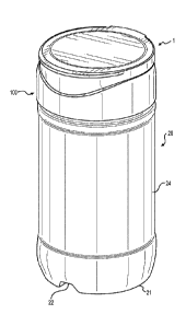
[0006] In embodiments, the dispenser package has an outer diameter of
between 1
and 2 inches and an overall axial length of between 3.5 and 4.5 inches.
[0007] In embodiments, the outer diameter is between 1.5 and 1.75
inches.
1
Date Regue/Date Received 2023-06-23
CA 03093560 2020-09-09
WO 2019/178363
PCT/US2019/022283
[0008] In embodiments, the overall axial length is between 3.75 and 4.25
inches.
[0009] In embodiments, the container body is one of substantially
transparent and
substantially translucent.
[0010] In embodiments, the container body is made of one of a recyclable
material
and glass.
[0011] In embodiments, the cap is made of one of a recyclable material
and
synthetic resin.
[0012] In embodiments, the living hinge is configured to retain the flip-
up lid in a
predetermined angular open position.
[0013] In embodiments, the predetermined angular open position is an
angle
between 20 degrees and 45 degrees relative to a vertical center axis of the
container body.
[0014] In embodiments, the predetermined angular open position is an
angle of
about 30 degrees relative to a vertical center axis of the container body.
[0015] In embodiments, a diameter of the outer circumferential surface is
about 1.25
inches.
[0016] In embodiments, the outer circumferential surface is outwardly
curved.
[0017] In embodiments, the outer circumferential surface may comprise an
outwardly curved surface and a circumferential indentation.
[0018] In embodiments, the inner circumferential surface may comprise a
projection.
[0019] In embodiments, the projection is disposed on a lower end of the
inner
circumferential surface when the flip-up lid is in a closed position and the
container body is
in an upright position.
[0020] In embodiments, the dispenser package contains a spice.
[0021] In embodiments, the spice is food seasoning, granules, plant seeds
or plant
leaves such as oregano.
[0022] In embodiments, the flip-up lid may comprise a projecting portion
disposed
on a front side of the flip-up lid and wherein the cap body may comprise a
recessed portion
disposed on a front side of the cap body.
[0023] In embodiments, the projecting portion disposed on the front side
of the flip-
up lid is outwardly curved and wherein the recessed portion disposed on the
front side of the
cap body is inwardly curved in a complementary manner.
[0024] In embodiments, the cap has an axial length of between 0.75 and 1
inch.
2
CA 03093560 2020-09-09
WO 2019/178363
PCT/US2019/022283
[0025] In
embodiments, the flip-up lid may comprise a main portion and an outer
portion that is at least a visually recognizable over-molded outer portion and
different in
color or texture than the main portion.
[0026] In
embodiments, the plural dispensing openings comprise three pie-shaped
pouring openings.
[0027] In
embodiments, the plural dispensing openings comprise five semi-pie-
shaped sifting openings.
[0028] In
embodiments, the plural dispensing openings comprise five sieve
openings;
[0029] The
invention also provides for a spice dispenser package container body
comprising a generally cylindrical transparent sidewall, a closed bottom
having an external
notch and semi-rounded projections, an open upper end extending to a circular
rim, a
removable seal closing off the open upper end and an external thread arranged
on the open
upper end.
[0030] The
invention also provides for a dispenser package cap configured to be
mount6ed to a spice container. The cap may comprise a generally cylindrical
cap body
securable to an upper end of the container body. The cap body may comprise a
generally
circular projecting portion having an outer circumferential surface and an
upper surface that
includes plural dispensing openings. A generally circular flip-up lid is
connected to the cap
body by a living hinge and being movable between a covering position and an
open
position. The flip-up lid may comprise an inner circumferential surface that
is engagable
with the outer circumferential surface of the projecting portion. The
engagement between
the inner circumferential surface and the outer circumferential surface is at
least one of a
snap-engagement which produces an audible sound when the flip-up lid is opened
and
closed and a sealing engagement which prevents an exchange of air between an
interior of
the dispenser package and an atmosphere outside the dispenser package.
[0031] The
invention also provides for a fully or nearly-fully recyclable spice or
seasoning dispenser package comprising a generally cylindrical transparent
container body
made of mostly recycled glass and having an open upper end of sufficient size
to permit
passage there-through of a tea spoon. A recyclable synthetic resin cap is
removably
mounted to the container body and may comprise a generally cylindrical cap
body securable
to an upper end of the container body. The cap body may comprise a generally
circular
projecting portion having an outer circumferential surface and an upper
surface that
includes plural dispensing openings. A flip-up lid is connected to the cap
body by a living
3
CA 03093560 2020-09-09
WO 2019/178363
PCT/US2019/022283
hinge and being movable between a covering position and an open position. A
finger
engagable portion at least partially surrounds an upper portion of the flip-up
lid, said finger
engagable portion being made of a softer, less-rigid and/or more flexible
material than a
main portion of the flip-up lid. The flip-up lid may comprise an inner
circumferential
surface that is engagable with the outer circumferential surface of the
projecting portion.
The living hinge is configured to retain the flip-up lid in a predetermined
angular open
position. The engagement between the inner circumferential surface and the
outer
circumferential surface is at least one of a snap-engagement which produces an
audible
sound when the flip-up lid is opened and/or closed and a sealing engagement
which
prevents an exchange of air between an interior of the dispenser package and
an atmosphere
outside the dispenser package.
[0032] In
embodiments, the flip-up lid may comprise an upper planar outer surface
configured to receive product identification indicia.
[0033] In
embodiments, an inside diameter of the open upper end is about 1.25
inches.
[0034] In
embodiments, the invention provides for a method of making the
dispenser package of anyone of types described above, wherein the method may
comprise
placing a food product inside the container body and mounting the cap to the
container
body.
BRIEF DESCRIPTION OF THE DRAWINGS
[0035] The
present invention is further described in the detailed description which
follows, in reference to the noted plurality of drawings by way of non-
limiting examples of
exemplary embodiments of the present invention, in which like reference
numerals
represent similar parts throughout the several views of the drawings, and
wherein:
Fig. 1 shows a perspective view of a dispenser package in accordance with the
invention;
Fig. 2 shows a front view of a dispenser package of Fig. 1;
Fig. 3 shows a back view of a dispenser package of Fig. 1;
Fig. 4 shows a left view of a dispenser package of Fig. 1;
Fig. 5 shows a right view of a dispenser package of Fig. 1;
Fig. 6 shows a top view of a dispenser package of Fig. 1;
Fig. 7 shows a bottom view of a dispenser package of Fig. 1;
Fig. 8 shows a cross-section view of a dispenser package of Fig. 5;
4
CA 03093560 2020-09-09
WO 2019/178363
PCT/US2019/022283
Fig. 9 shows a perspective view of the container body used in the dispenser
package
of Fig. 1;
Fig. 10 shows a front view of a dispenser package of Fig. 9;
Fig. 11 shows a back view of a dispenser package of Fig. 9;
Fig. 12 shows a top view of a dispenser package of Fig. 9;
Fig. 13 shows a bottom view of a dispenser package of Fig. 9;
Fig. 14 shows a cross-section view of a dispenser package of Fig. 10;
Fig. 15 shows a perspective view of a transparent version of the container
body used
in the dispenser package of Fig. 1;
Fig. 16 shows a perspective view of the cap used in the dispenser package of
Fig. 1;
Fig. 17 shows a front view of the cap of Fig. 16;
Fig. 18 shows a back view of the cap of Fig. 16;
Fig. 19 shows a left view of the cap of Fig. 16;
Fig. 20 shows a right view of the cap of Fig. 16;
Fig. 21 shows a top view of the cap of Fig. 16;
Fig. 22 shows a perspective view of one embodiment of the cap of Fig. 16 in an
open position;
Fig. 23 shows a front view of the cap of Fig. 22;
Fig. 24 shows a back view of the cap of Fig. 22;
Fig. 25 shows a right view of the cap of Fig. 22;
Fig. 26 shows a left view of the cap of Fig. 22;
Fig. 27 shows a top view of the cap of Fig. 22;
Fig. 28 shows a cross-section view of the cap of Fig. 20;
Fig. 29 shows a bottom view of the cap of Fig. 17;
Fig. 30 shows a cross-section view of one embodiment of the cap of Fig. 16 in
a
partially open position;
Fig. 31 shows a cross-section view of one embodiment of the cap of Fig. 16 in
a
fully open position;
Fig. 32 shows a perspective view of another embodiment of the cap of Fig. 16
in an
open position;
Fig. 33 shows a front view of the cap of Fig. 32;
Fig. 34 shows a back view of the cap of Fig. 32;
Fig. 35 shows a right view of the cap of Fig. 32;
Fig. 36 shows a left view of the cap of Fig. 32;
CA 03093560 2020-09-09
WO 2019/178363
PCT/US2019/022283
Fig. 37 shows a top view of the cap of Fig. 32;
Fig. 38 shows a perspective view of another embodiment of the cap of Fig. 16
in an
open position;
Fig. 39 shows a front view of the cap of Fig. 38;
Fig. 40 shows a back view of the cap of Fig. 38;
Fig. 41 shows a right view of the cap of Fig. 38;
Fig. 42 shows a left view of the cap of Fig. 38;
Fig. 43 shows a top view of the cap of Fig. 38;
Fig. 44 shows a top view of an exemplary seal member that can be removably
secured to a rim of the container body; and
Fig. 45 shows a side view of the seal member of Fig. 44.
DETAILED DESCRIPTION OF THE INVENTION
[0036] The following detailed description illustrates by way of example, not
by way of
limitation, the principles of the disclosure. This description will clearly
enable one skilled
in the art to make and use the disclosure, and describes several embodiments,
adaptations,
variations, alternatives and uses of the disclosure, including what is
presently believed to be
the best mode of carrying out the disclosure. It should be understood that the
drawings are
diagrammatic and schematic representations of exemplary embodiments of the
disclosure
and are not limiting of the present disclosure nor are they necessarily drawn
to scale.
[0037] The novel features which are characteristic of the disclosure, both as
to structure
and method of operation thereof, together with further aims and advantages
thereof, will be
understood from the following description, considered in connection with the
accompanying drawings, in which an embodiment of the disclosure is illustrated
by way of
example. It is to be expressly understood, however, that the drawings are for
the purpose of
illustration and description only, and they are not intended as a definition
of the limits of the
disclosure.
[0038] In the
following description, the various embodiments of the present disclosure
will be described with respect to the enclosed drawings. As required, detailed
embodiments
of the present disclosure are discussed herein; however, it is to be
understood that the
disclosed embodiments are merely exemplary of the embodiments of the
disclosure that
may be embodied in various and alternative forms. The figures are not
necessarily to scale
and some features may be exaggerated or minimized to show details of
particular
components. Therefore, specific structural and functional details disclosed
herein are not to
6
CA 03093560 2020-09-09
WO 2019/178363
PCT/US2019/022283
be interpreted as limiting, but merely as a representative basis for teaching
one skilled in the
art to variously employ the present disclosure.
[0039] The
particulars shown herein are by way of example and for purposes of
illustrative discussion of the embodiments of the present disclosure only and
are presented
in the cause of providing what is believed to be the most useful and readily
understood
description of the principles and conceptual aspects of the present
disclosure. In this regard,
no attempt is made to show structural details of the present disclosure in
more detail than is
necessary for the fundamental understanding of the present disclosure, such
that the
description, taken with the drawings, making apparent to those skilled in the
art how the
forms of the present disclosure may be embodied in practice.
[0040] As used herein, the singular forms "a," "an," and "the" include the
plural reference
unless the context clearly dictates otherwise. For example, reference to "a
material" would
also mean that mixtures of one or more materials can be present unless
specifically
excluded. As used herein, the indefinite article "a" indicates one as well as
more than one
and does not necessarily limit its referent noun to the singular.
[0041] Except where otherwise indicated, all numbers expressing quantities
used in the
specification and claims are to be understood as being modified in all
examples by the term
"about." Accordingly, unless indicated to the contrary, the numerical
parameters set forth in
the specification and claims are approximations that may vary depending upon
the desired
properties sought to be obtained by embodiments of the present disclosure. At
the very
least, and not to be considered as an attempt to limit the application of the
doctrine of
equivalents to the scope of the claims, each numerical parameter should be
construed in
light of the number of significant digits and ordinary rounding conventions.
[0042]
Additionally, the recitation of numerical ranges within this specification is
considered to be a disclosure of all numerical values and ranges within that
range (unless
otherwise explicitly indicated). For example, if a range is from about 1 to
about 50, it is
deemed to include, for example, 1, 7, 23.7, 34, 46.1 or any other whole number
or decimal
value or range within the range.
[0043] As used herein, the terms "about" and "approximately" indicate that the
amount or
value in question may be the specific value designated or some other value in
its
neighborhood. Generally, the terms "about" and "approximately" denoting a
certain value is
intended to denote a range within 5% of the value. As one example, the
phrase "about
100" denotes a range of 100 5, i.e. the range from 95 to 105. Generally,
when the terms
"about" and "approximately" are used, it can be expected that similar results
or effects
7
CA 03093560 2020-09-09
WO 2019/178363
PCT/US2019/022283
according to the disclosure can be obtained within a range of 5% of the
indicated value.
[0044] As
used herein, the term "and/or" indicates that either all or only one of the
elements of said group may be present. For example, "A and/or B" shall mean
"only A, or
only B, or both A and B". In the case of "only A", the term also covers the
possibility that B
is absent, i.e. "only A, but not B".
[0045] The
term "at least partially" is intended to denote that the following property is
fulfilled to a certain extent or completely.
[0046] The terms "substantially" and "essentially" are used to denote that the
following
feature, property or parameter is either completely (entirely) realized or
satisfied or to a
major degree that does not adversely affect the intended result.
[0047] The term "comprising" as used herein is intended to be non-exclusive
and open-
ended. Thus, for example a composition comprising a compound A may include
other
compounds besides A. However, the term "comprising" also covers the more
restrictive
meanings of "consisting essentially of' and "consisting of', so that for
example "a
composition comprising a compound A" may also (essentially) consist of the
compound A.
Similarly, a device or element comprising feature A may include other features
besides A.
[0048] The various embodiments disclosed herein can be used separately and in
various
combinations unless specifically stated to the contrary.
[0049] The present invention is further described in the detailed description
which follows,
in reference to exemplary embodiments.
[0050] Figs. 1-14 show a first non-limiting embodiment of a dispenser package
1. The
dispenser package 1 includes two main components which include a container or
container
body 20, a cap 100, and also an optional removable seal 10 (see Figs. 44 and
45). As shown
in Fig. 1, the cap 100 is arranged on an upper end of the container 20 which
has a sidewall
24 and a bottom 21 that can be notched 22.
[0051] The removable seal 10, as exemplified in Figs. 44 and 45 can be used
with any of
the herein noted embodiments, and is a sheet-like member having a layer that
can be readily
adhered to a rim 27 of the container 20 so as to function as a tamper-proof or
tamper-
evident element. In accordance with non-limiting aspects of the invention, a
consumer will
typically remove the cap 100 from the container 20 to access the container rim
27, which
will have the seal 10 adhered thereto, i.e., a peripheral area of a lower
surface of the seal 10
will be releasably adhered to the rim 27. The one or more projecting tabs of
the seal 10
allow the user to grip the seal 10 and peel the same off of the rim 27. Once
the seal 10 is
removed or peeled-off, the consumer can re-install the cap 100 and use the
dispenser
8
CA 03093560 2020-09-09
WO 2019/178363
PCT/US2019/022283
package 1 as intended. However, as the seal 10 can be attached to the rim 17
initially, the
consumer can be assured that the contents have not been previously tampered
with, have not
been added to, and/or have not been reduced prior to purchase or use.
[0052] Referring to Figs. 2-7, it can be seen that the cap 100 has a front
projection or lip
123 that allows a user to grip and lift-up the flip-up lid 118. The flip-up
lid 118 is
connected at a rear side of a skirt 101 of the cap 100 by living hinge system
119 made up of
plural integral hinges 119A, 119B and 119C. The hinge system 119 is such that
they
function as a spring so that upon lifting up the front of the flip-up lid 118
to a certain extent,
they cause the flip-up lid 118 to swing to a predetermined open position
similar to that
shown in Fig. 30. The skirt 101 forms part of a cap body and has a somewhat
tapered outer
surface 102 which generally enlarges toward the container. The container
bottom 21 can
have alignment notches 22 and plural genera11y7 circular or rounded
projections 23 as
shown in Fig. 7. The container 20 can be made of synthetic resin or glass, and
can have a
generally uniform thickness wall as shown in Fig. 8.
[0053] With reference to Figs. 9-14, it can be seen that the container body 20
can be a one-
piece member that somewhat resembles a glass jar and that includes the bottom
21 with one
or more notches 22 and projections 23, as discussed above, as well as an
indented center
portion (also arranged on the bottom 21) and including a generally cylindrical
sidewall 24
that extends from a slightly bulbous portion located near the bottom 21 to a
neck 25. The
neck 25 has a reduced diameter section which includes an external thread 26
and a circular
rim 27. The rim 27 defines an opening 28 and this opening 28 can be sized to
be large
enough to receive a tea spoon so as to allow contents to be spooned out if
desired.
[0054] In Figs. 1-14, one can see an embodiment where the container 20 is
opaque.
However, the container 20' can also be translucent or transparent as shown in
Fig. 15 so as
to allow a user or consumer to view the contents and/or the quantity of the
same therein.
[0055] As shown in Figs 16-31, the cap 100 can include a skirt 101 having a
slightly
tapered outer surface 102 and an inner surface 103 having an inner or internal
thread 104.
The thread 104 is sized and configured to engage with the outer thread 26 of
the container
20. As can be seen in Fig. 22, an annular upper end 105 is arranged on the cap
100 and
surrounds a projecting portion 106, which includes a curved outer
circumferential surface
107 and a circumferential recess 108. A dispensing wall 110 includes a planar
surface 111
and dispensing openings 112, which in some embodiments define closed areas or
spokes
113. An inwardly curved recess or indentation 114 is located at a front side
of the cap 100.
The recess 114 can accommodate the outwardly curved front portion of the lid
118 which
9
CA 03093560 2020-09-09
WO 2019/178363
PCT/US2019/022283
includes the surfaces 124 and 125. Inside the cap 100, there is located an
inner circular
flange 115 having a flange rim 116 and an annular space 117 (see Figs. 22 and
28).
[0056] As noted above and evident from Figs. 16-31, the cap 100 includes a
flip-up lid or
cover 118 that can be moved to at least an open and a closed position. The lid
118 is
connected to skirt 101 via a living hinge system 119 which can be formed by
hinge parts
119A, 119B and 119C. The lid 118 has a planar upper surface 120 and a planar
inner
surface 121. A finger engaging portion 122 can be made of different material,
e.g. softer,
less rigid, and/or more flexible than a main part of the lid, and can be over-
molded onto the
lid 118. A lift-up projection 123 is located on a front side of the portion
122 and a lower
curved projection 124 is located on a lower front side thereof. An inner
circumferential
surface 130 includes one or more circumferential retaining projections 126 and
these are
arranged on a circular retaining flange 127. The projections 126 are
configured to engage
with the recess 108 when the lid 118 is in a closed position and functions to
retain the
closed position. This projection/recess engagement is released or disengages
when the user
exerts pressure on the projection 123 to move the lid 118 to the open
position. The
circumferential surfaces having the projections 126 and recess 108 can
function to provide a
sealing engagement between the lid 118 and cap body. The cap 100 also includes
a guide
projection 128 that engages with a guide recess 129. To facilitate proper
opening or closing
of the lid 118, a guide projection 128 can engage with a guide recess 129.
This is further
facilitated by the rounded or tapered shape of the surface 107 In the closed
position of the
lid 118, the surface 124 will be positioned close to or abut the comparably
shaped recess
114. As is apparent from Figs. 30 and 31, the lid 118 can be opened to a
predetermined
position as shown in Fig. 30 and be retained therein by action of the hinge
system 119, or it
can be moved to a more fully open position shown in Fig. 31 by action of the
consumer or
user.
[0057] Figs. 32-37 show another exemplary cap 100'. Unlike the previous cap
which
employed a larger number of smaller openings in the dispensing wall, this
embodiment
employs a smaller number of larger dispensing openings 112' located between
spokes 113'.
The cap 100' can otherwise include all of the same features as the previous
embodiment
such as the living hinge system 119' and flip-up lid 118'. The size of the
openings 112' can
be tailored to the product being dispensed so that, for example, with a
product such as
ground pepper, the openings 112' shown in Fig. 32 can allow for this substance
to be
poured out. On the other hand, with the smaller openings of the previous
embodiment, the
CA 03093560 2020-09-09
WO 2019/178363
PCT/US2019/022283
same ground pepper can be sprinkled out during the product dispensing. Like
the previous
embodiment, the cap 100' can be used with either container 20 or 20' described
above.
[0058] Figs. 38-43 show another exemplary cap 100". Unlike the previous caps
which
employed either a larger number of smaller openings in the dispensing wall or
vice versa,
this embodiment employs smaller size dispensing openings 112". The cap 100"
can
otherwise include all of the same features as the previous embodiment such as
the living
hinge system 119" and flip-up lid 118". As with the previous embodiments, the
size of the
openings 112" can be tailored to the product being dispensed so that, for
example, with a
product such as salt, the openings 112" shown in Fig. 38 can allow for this
substance to be
sifted out. Like the previous embodiment, the cap 100" can be used with either
container
20 or 20' described above.
Example A
[0059] A fully or nearly-fully recyclable spice or seasoning dispenser package
1 comprises
a generally cylindrical transparent container body 20 made of mostly recycled
glass and
having an open upper end 27/28 of sufficient size to permit passage there-
through of a tea
spoon. A recyclable synthetic resin cap 100 is removably mounted to the
container body
20. The cap 100 comprises a generally cylindrical cap body securable to an
upper end of
the container body 20. The cap body comprises a generally circular projecting
portion 106
having an outer circumferential surface 107 and an upper surface 110 that
includes plural
dispensing openings 112. These can be openings 112, 112' or 112" as well as
any
combination thereof. A flip-up lid 118 is connected to the cap body by a
living hinge 119
(119A, 119B and 119C) and is movable between a covering or closed position and
an open
position. A finger engagable portion 122 at least partially surrounds an upper
portion of the
flip-up lid 118. The finger engagable portion 122 is made of a softer, less-
rigid and/or more
flexible material than a main portion of the flip-up lid 118. The flip-up lid
118 comprises
an inner circumferential surface 130 that is engagable with the outer
circumferential surface
107 of the projecting portion 106. The living hinge 119 is configured to
retain the flip-up
lid 118 in a predetermined angular open position. The engagement between the
inner
circumferential surface 130 and the outer circumferential surface 107 is at
least one of a
snap-engagement produces an audible sound when the flip-up lid 118 is opened
and/or
closed and a sealing engagement which prevents an exchange of air between an
interior of
the dispenser package 1 and an atmosphere outside the dispenser package 1. The
flip-up lid
118 comprises an upper planar outer surface 120 configured to receive product
identification indicia. An inside diameter of the open upper end 28 is about
1.25 inches.
11
CA 03093560 2020-09-09
WO 2019/178363
PCT/US2019/022283
Example B
[0060] A synthetic resin dispenser package cap 100 is configured to be mounted
to a spice
or seasoning container 20. The cap 100 comprises a generally cylindrical cap
body
securable to an upper end of the container body 20. The cap body comprises a
generally
circular projecting portion 106 having an outer circumferential surface 107
and an upper
surface 110 that includes plural dispensing openings 112, an outer skirt 101
and a generally
circular projecting flange 115 having a shorter axial length than the outer
skirt 101. The
openings can be openings 112, 112' or 112" as well as any combination thereof.
The
flange 115 is located inside the outer skirt 101 and has a circular rim 116
configured to
contact a rim 27 of a container body 20 receiving said cap 100. A generally
circular flip-up
lid 118 is connected to the cap body by a living hinge 119 and is movable
between a
covering or closed position and an open position. The flip-up lid 118
comprising an inner
circumferential surface 130 that is engagable with the outer circumferential
surface 107 of
the projecting portion 106. A finger engagable portion 122 at least partially
surrounds an
upper portion of the flip-up lid 118. The finger engagable portion 122 is made
of a softer,
less-rigid and/or more flexible material than a main portion of the flip-up
lid 118. The
engagement between the inner circumferential surface 130 and the outer
circumferential
surface 107 is at least one of a snap-engagement produces an audible sound
when the flip-
up lid 118 is opened and closed. A sealing engagement which prevents an
exchange of air
between an interior of the dispenser package 1 and an atmosphere outside the
dispenser
package 1 when the cap is in an installed state.
Example C
[0061] A spice dispenser package container body 20' has a volume of about 3
ounces and is
made of mostly recyclable glass. The container body 20' comprises a generally
continuously cylindrical transparent sidewall 24', a closed bottom 21' having
an external
notch 22' and semi-rounded projections 23'. A reduced diameter upper end 24'
extends to a
circular rim 27'. An external thread 26' is arranged on the reduced diameter
upper end 25'.
A removable seal 10 may close off the open upper end 27728'.
[0062] Further, at least because the invention is disclosed herein in a manner
that enables
one to make and use it, by virtue of the disclosure of particular exemplary
embodiments,
such as for simplicity or efficiency, for example, the invention can be
practiced in the
absence of any additional element or additional structure that is not
specifically disclosed
herein.
12
CA 03093560 2020-09-09
WO 2019/178363
PCT/US2019/022283
[0063] It is noted that the foregoing examples have been provided merely for
the purpose of
explanation and are in no way to be construed as limiting of the present
invention. While
the present invention has been described with reference to an exemplary
embodiment, it is
understood that the words which have been used herein are words of description
and
illustration, rather than words of limitation. Changes may be made, within the
purview of
the appended claims, as presently stated and as amended, without departing
from the scope
and spirit of the present invention in its aspects. Although the present
invention has been
described herein with reference to particular means, materials and
embodiments, the present
invention is not intended to be limited to the particulars disclosed herein;
rather, the present
invention extends to all functionally equivalent structures, methods and uses,
such as are
within the scope of the appended claims.
List of Reference Numbers
Dispenser Package 1
Removable Seal 10
Container body 20
Bottom 21
Notch 22
Projections 23
Sidewall 24
Neck 25
External thread 26
Rim 27
Opening 28
Cap 100
Skirt 101
Tapered outer surface 102
Inner surface 103
Inner thread 104
Annular upper end 105
Projecting Portion 106
Curved outer Cir. surface 107
Circumferential recess 108
13
CA 03093560 2020-09-09
WO 2019/178363
PCT/US2019/022283
Dispensing part 110
Planar surface 111
Dispensing openings 112
Spokes 113
Inwardly curved recess 114
Inner circular flange 115
Flange rim 116
Annular space 117
Flip-up lid 118
Living hinge 119
Hinge part 119A
Hinge part 119B
Hinge part 119C
Planar upper surface 120
Planar inner surface 121
Finger engaging portion 122
Lift-up projection 123
Lower curved projection 124
Inner circum. surface 125
Circum. retaining projection 126
Circular retaining flange 127
Guide projection 128
Guide recess 129
Inner cylindrical surface 130
The above reference numbers can have similar numbers identified with a prime
and double
prime indicator to identify other embodiments. For example, ref. 20 can be 20'
or 20".
14