Note: Descriptions are shown in the official language in which they were submitted.
CA 03093909 2020-09-14
WO 2019/178340 PCT/US2019/022237
CONNECTOR AND CONNECTOR INSERT FOR PROTECTING CONDUCTOR
SPRING-ELEMENTS
BACKGROUND
[0001] Telecommunications systems often employ hardline connectors
for
data transfer between telecom components, e.g., a Remote Radio Unit (RRU) and
a
telecommunications sector antenna. These hardline connectors often employ an
arrangement of spring-biased fingers/elements for making the requisite
electrical
connections, e.g., signal or electrical ground connections, from one connector
to a
mating connector. One type of connector, known as a 4.3-10 Connector, commonly
employs a multi-fingered inner conductor socket surrounded by a multi-fingered
outer
connector basket which receive an inner conductor pin and an outer conductor
sleeve,
respectively, of an adjoining/opposing connector.
[0002] The geometric similarity between connectors, in combination
with
the difficulty associated with physically making an electrical connection,
i.e., fifty (50)
feet in the air, can cause Linemen to improperly/incorrectly join connectors.
While
connectors which do not properly mate will, in most instances, not be able to
be joined
(i.e., to affect a viable telecommunications connection), the attempt alone
can damage
or, otherwise distort, at least one of the conductors.
[0003] Particularly vulnerable are the fingers of the outer
conductor
basket. For example, a Mini-Din connector, which is also an RF connector used
in the
telecommunications industry, is sufficiently similar in appearance that one
might
inadvertently try to connect a Mini-Din plug to a 4.3-10 jack. Unfortunately,
when
applying the requisite force to establish the connection, the structure of the
Mini-Din
- 1 -
CA 03093909 2020-09-14
WO 2019/178340 PCT/US2019/022237
plug may press against and force the finger elements of the 4.3-10 outer
conductor
basket in an outwardly direction. Not only does this cause an improper RF
connection,
but it can damage the 4.3-10 jack, requiring that it be replaced. Inasmuch as
the
connector is, most often, an integral component of an electronic component,
e.g., a
Remote Radio Unit or an antenna, a seemingly small amount of damage to the
connector can incapacitate a very costly piece of telecommunications
equipment, i.e., a
component which may cost between $20K to $40K to replace.
[0004] Therefore, a need exists to overcome, or otherwise lessen
the
effects of, the disadvantages and shortcomings described above.
BRIEF DESCRIPTION OF THE DRAWINGS
[0005] Additional features and advantages of the present disclosure
are
described in, and will be apparent from, the following Brief Description of
the Drawings
and Detailed Description.
[0006] Fig. 1 is an exploded view of a 4.3-10 connector including:
(a) a first
connector or connector portion comprising a multi-fingered inner conductor
socket
surrounded by multi-fingered outer conductor basket, (b) a second connector or
connector portion comprising an inner conductor pin surrounded by a
cylindrical sleeve,
and (c) a corrugated, pedal-shaped cylindrical wall or tube disposed between
the socket
and the basket configured to: (i) inhibit plastic deformation of the axially
projecting
fingers of the outer conductor basket should a mating connector be insert at a
damaging
angle or inclination, or (ii) prevent insertion of a non-mating connector
between the
socket and the basket so as to protect/support the outer conductor basket.
- 2 -
CA 03093909 2020-09-14
WO 2019/178340 PCT/US2019/022237
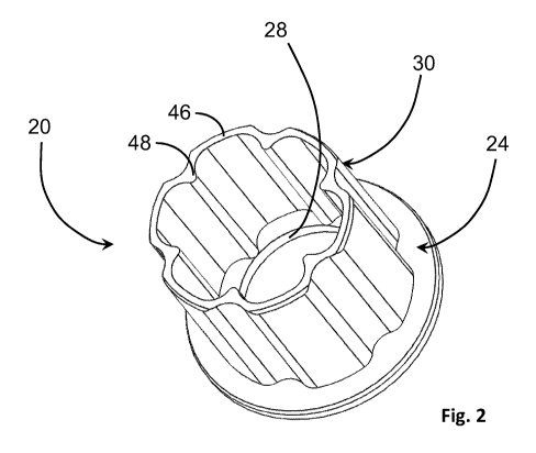
[0007] Fig. 2 is an enlarged, isolated, perspective view of the
insert
according to the teachings of the present disclosure.
[0008] Fig. 3 is an enlarged, isolated, side view of the insert
according to
the teachings of the present disclosure.
[0009] Fig. 4 is an enlarged, isolated, front view of the insert
according to
the teachings of the present disclosure.
[0010] Fig. 5 is a partially broken away, sectional view of the
first
connector including an insert disposed between the inner conductor socket and
the
outer conductor basket to inhibit, block or reject attempts to mate improperly-
sized
connectors along with the potentially damaging consequences to the basket
fingers of
the outer conductor.
[0011] Fig. 6 is an enlarged, partially broken away and sectioned
view of
the first connector depicted in Fig. 5 to facilitate illustration of the
relationship between,
and the various features of, the basket fingers and the connector insert.
[0012] Fig. 7 depicts a view of a non-mating connector being
rejected or
inhibited by the insert during an attempt to join the incompatible connectors.
[0013] Fig. 8 depicts a view of the first and second connectors
being
joined at a potentially damaging angle of inclination, and the role of the
insert to protect
the basket fingers by preventing excessive strain or plastic deformation
thereof so as to
maintain the elastic properties of the basket fingers for subsequent
connection with the
outer conductive sleeve of the second connector.
- 3 -
CA 03093909 2020-09-14
WO 2019/178340 PCT/US2019/022237
SUMMARY OF THE INVENTION
[0014] In one embodiment of the disclosure, a connector is provided
comprising a center or inner conductor socket, an outer conductor basket and
an
inhibitor or insert disposed between the inner conductor socket and the outer
conductor
basket. The inner conductor socket transmits RF signals from one connector
portion to
another connector portion across a mating interface. The outer conductor
basket
comprises a plurality of axially projecting fingers configured to electrically
ground the
connector. The inhibitor comprises an insert disposed along the outwardly
facing
surface of the outer conductor basket to prevent damage to the axially
projecting fingers
in an unassembled condition/state, thereby ensuring electrical connectivity of
the fingers
in an assembled condition/state. Functionally, the insert prohibits insertion
of a non-
mating connector so as to prevent plastic deformation of the axially
projecting fingers
and permanent distortion thereof which would otherwise prevent a proper
electrical
connection between the fingers of the basket and a cylindrical outer conductor
sleeve of
a mating connector. Specifically, the insert is configured to prevent one of
the following:
(i) insertion of a non-mating connector between the socket and basket of the
other
connector, (ii) misalignment of a pair of mating connectors during assembly of
the
connectors, and (iii) plastic deformation of at least one of the axially
projecting fingers of
the mating connectors.
[0015] In another embodiment, a connector insert is configured to
inhibit
plastic deformation of at least one of the axially projecting fingers of an
outer conductor
basket associated with one of the connectors. The connector insert comprises:
(i) an
outwardly facing flange configured to engage a shoulder formed at a base of
the axially
- 4 -
CA 03093909 2020-09-14
WO 2019/178340 PCT/US2019/022237
projecting fingers of the outer conductor basket, (ii) a tubular structure
defining an
elongate axis and having plurality of engagement sections extending normal to
the
outwardly facing flange, and (iii) a plurality of stiffening sections having a
surface
disposed substantially parallel to a radial projecting from the elongate axis.
Each of the
engagement sections also have a surface disposed substantially normally to a
radial
projecting from the elongate axis.
[0016] The engagement sections function to prevent plastic
deformation of
the axially projecting fingers, thereby preventing damage to the fingers
and/or the
transmission of RF signals. The stiffening sections function to support the
engagement
sections, while furthermore, preventing the insertion of a non-mating second
connector
into, or against, the outer conductor basket of a first connector.
DETAILED DESCRIPTION
[0017] A connector is described including first and second
connectors or
connector portions each comprising electrically-connecting inner and outer
conductors.
While the connector includes first and second mating connector portions, it
should be
understood and appreciated that, in the context used herein, a "connector"
means either
or both of the connector portions.
[0018] The following describes a connector, for example, a 4.3-10
connector, and a protective insert for inhibiting or mitigating damage to a
multi-fingered
spring-biased outer conductor basket of the connector. While the insert is
particularly
useful for 4.3-10 connectors, it should be appreciated that the protective
insert, and the
teachings associate therewith, are equally applicable to a wide-variety of
- 5 -
CA 03093909 2020-09-14
WO 2019/178340 PCT/US2019/022237
telecommunications/signal connectors. The protective insert of the present
disclosure
has utility when the 4.3-10 connector is unassembled, and/or is being prepared
for
assembly. Specifically, the insert prevents damage to a first connector in the
event that
a non-mating second connector, i.e., a connector of a different size or
variety, such as a
Mini-Din connector, is forcibly urged into engagement with the first
connector. As such,
the protective insert may prevent a costly error.
[0019] In Fig. 1, a pair of mating connectors 10 is depicted
including a first
connector 12 and a second connector 14 each having an inner conductor 16 and
an
outer conductor 18. An inhibitor or insert 20 is disposed in combination with
at least one
of the connectors 12, and in the illustrated embodiment, the insert 20 is
disposed
between a multi-fingered inner conductor socket 16, and a multi-fingered outer
conductor basket 18 of the first connector 12. The 4.3-10 connectors 10 of the
type
described herein may have an impedance of about fifty Ohms (500) with a
frequency
range of between about one kilohertz (1.0 kHz) to about six gigahertz (6.0
GHz.),
although variations to the connector parameters are possible and within the
scope of
the disclosure.
[0020] In Figs. 2 and 6, the individual fingers 16f of the inner
conductor
socket 16 are spring-biased inwardly such that the fingers 16f may
collectively capture
or frictionally engage an inner conductor pin (not seen) of the second
connector 14.
Conversely, the individual fingers 18f of the outer conductor basket 18 are
spring-biased
outwardly such that the fingers 18f may collectively capture or frictionally
engage an
outer conductor sleeve of the second connector 14.
- 6 -
CA 03093909 2020-09-14
WO 2019/178340 PCT/US2019/022237
[0021] In Figs. 2 through 6, the insert 20 defines an outwardly
facing
flange 24 configured to engage a shoulder 26 formed at the base of the axially
projecting fingers 18f of the outer conductor basket 18. Furthermore, the
outwardly
facing flange 24 defines an aperture 28 (see Figs. 2, 4 and 6) configured to
receive the
axially projecting fingers 16f of the inner conductor socket 16 (best seen in
Fig. 6).
Finally, the insert 20 comprises a corrugated, wave, or pedal-shaped tubular
structure 30 defining an elongate axis A (projecting normally from a plane
defined by the
outwardly facing flange 24,) i.e., out of the page with respect to Fig. 4.
[0022] The corrugated, wave or pedal-shaped tube 30, furthermore,
defines outwardly bulging, engagement sections 46, and inwardly projecting,
stiffening
sections 48 which vary in radial dimension R from the elongate axis A. To
facilitate the
subsequent narrative, each outwardly bulging section will be referred to as an
"engagement section" and each inwardly projecting section will be referred to
as a
"stiffening section". In the described embodiment, the engagement section 46
includes
a substantially arcuate, outwardly-facing surface 46S, which is disposed
substantially
normal to a radial line RL projecting from the elongate axis A. Each
engagement
section 46 functions to oppose the inward radial displacement of the axially
projecting
fingers 18f of the outer conductor basket 18 such that the displacement, or
elongation,
of the axially projecting fingers 18f does not extend into the plastic region
or into the
plastic deformation range of the strain allowable, i.e., the non-linear
portion of the strain
curve. That is, the engagement section 46 limits the displacement of the
axially
projecting fingers 18f such that the deformation remains in the elastic region
of the
material, i.e., does not extend into the plastic deformation range of the
material.
- 7 -
CA 03093909 2020-09-14
WO 2019/178340 PCT/US2019/022237
[0023] In the illustrated embodiment, the insert 20 includes at
least
three (3) engagement sections, each spanning a first arcuate region alpha a
and at
least three (3) stiffening sections each spanning a second arcuate region Beta
13. More
specifically, each of the first arcuate regions alpha a may span an arc of at
least about
nighty-degrees (90) whereas each of the second arcuate regions Beta 13 may
span an
arc of at least about thirty (30) degrees. The illustrated embodiment depicts
a total of
six (6) engagement sections 46, and six (6) stiffening sections 48 wherein the
latter form
V-shaped notches between adjacent pairs of engagement sections 46. Each of the
first
arcuate regions alpha a span an arc of about thirty (30) degrees whereas each
of the
second arcuate regions Beta 13 span an arc of about twenty (20) degrees. About
ten (10) degrees is dedicated to the transition between the engagement and
stiffening
sections 46, 48 or about five (5) degrees to either side of each engagement
and
stiffening section 46, 48.
[0024] To minimize the impact that the insert 20 has on the
impedance
properties of the connector 10, the stiffening sections 48 are distally spaced
from the
fingers 16f of the socket 16. More specifically, the stiffening sections 48
stop short of
projecting inwardly toward the socket 16 and leave a gap between socket 16 and
each
stiffening section 48. In the described embodiment, the stiffening sections 48
extend
inwardly to a radius which is less than about one-half (1/2P) of the total
radius R
extending from the elongate axis A to the outer surface of the tubular
structure 30.
More specifically, the stiffening sections 48 extend inwardly to a radius
which is less
than about two-thirds (2/3rd5) of the total radius R. As such, the insert 20
has a singular
- 8 -
CA 03093909 2020-09-14
WO 2019/178340 PCT/US2019/022237
tube 30 with a plurality of V-shaped stiffening sections or ribs 48 which do
not extend or
connect to an inner ring or sleeve.
[0025] Moreover, each of the stiffening sections 48 project
radially
inwardly relative to the engagement sections 46 and function to enhance the
buckling
stability of each engagement section 46. In addition to providing buckling
stability, each
of the stiffening sections 48 inhibit or prevent the insertion of a non-mating
connector
(see Fig. 7) into the annular-shaped cavity between the inner conductor socket
16 and
the outer conductor basket 18 of the connector 12. The increased bending
stiffness of
the tubular structure 30 also prevents the axially projecting fingers 18f from
deformation
into the plastic range of the material elongation properties while promoting
axial
alignment of the mating connectors 12, 14. The features and function of the
connector 10, along with its insert 20, are shown and described in connection
with
figures 7 and 8.
[0026] Fig. 7 depicts an assembly view of a non-mating second
connector 54 being joined with the first connector 12. The view shows the
cylindrical
sleeve 56 abutting the leading or top surface 58 of the insert 20. While the
male and
female threads, 60 and 62, respectively, may be compatible, the insert 20
prevents the
threads 60, 62 from engaging. As such, there is no opportunity for the axially
projecting
fingers 18f to be spread or damaged by the outer conductor sleeve of the non-
mating
second connector 54.
[0027] Fig. 8 depicts a view of the first and second connectors 12,
14
being joined at a potentially damaging angle or inclination. Similar to the
prior example,
the role of the insert 20 is the protection of the basket fingers 18f. In this
particular
- 9 -
CA 03093909 2020-09-14
WO 2019/178340 PCT/US2019/022237
example, greater emphasis is placed on the exposure of the fingers 18f to
excessive
strain or plastic deformation. More specifically, the insert 20 is
sufficiently rigid or stiff
such that the fingers 18f are never exposed to a high level of strain, i.e., a
level which
would plastically deform a finger of the basket 18. Accordingly, the insert 20
promotes
realignment of the connectors 12, 14 rather than damage to one of the
connectors 12, 14. That is, the outer conductor sleeve 64 is guided into
alignment by
the insert 20.
[0028] Additional embodiments include any one of the embodiments
described above, where one or more of its components, functionalities or
structures is
interchanged with, replaced by or augmented by one or more of the components,
functionalities or structures of a different embodiment described above.
[0029] It should be understood that various changes and
modifications to
the embodiments described herein will be apparent to those skilled in the art.
Such
changes and modifications can be made without departing from the spirit and
scope of
the present disclosure and without diminishing its intended advantages. It is
therefore
intended that such changes and modifications be covered by the appended
claims.
[0030] Although several embodiments of the disclosure have been
disclosed in the foregoing specification, it is understood by those skilled in
the art that
many modifications and other embodiments of the disclosure will come to mind
to which
the disclosure pertains, having the benefit of the teaching presented in the
foregoing
description and associated drawings. It is thus understood that the disclosure
is not
limited to the specific embodiments disclosed herein above, and that many
50m0dificati0n5 and other embodiments are intended to be included within the
scope of
- 10 -
CA 03093909 2020-09-14
WO 2019/178340 PCT/US2019/022237
the appended claims. Moreover, although specific terms are employed herein, as
well
as in the claims which follow, they are used only in a generic and descriptive
sense, and
not for the purposes of limiting the present disclosure, nor the claims which
follow.
- 11 -