Note: Descriptions are shown in the official language in which they were submitted.
CA 03094060 2020-09-15
WO 2019/182505
PCT/SE2019/050259
1
PANELS COMPRISING A MECHANICAL LOCKING DEVICE AND AN ASSEMBLED
PRODUCT COMPRISING THE PANELS
Technical Field
Embodiments of the present invention relate to panels that may be arranged
perpendicular to each other and locked together with a mechanical locking
device. The
panels may be assembled and locked together to obtain a furniture product,
such as a
bookshelf, a cupboard, a wardrobe, a box, a drawer or a furniture component.
The
locking device may comprise a flexible tongue.
Background
A furniture product provided with a mechanical locking device is known in the
art, as
evidenced by WO 2017/131574. The furniture comprises a first panel connected
perpendicular to a second panel by a mitre joint which includes a mechanical
locking
device.
Summary
One object of certain embodiments of the present invention is to provide an
improvement over the above described technique and the known art. A specific
objective is to improve assembling of panels, such as furniture panels, locked
together
by a mechanical locking device and to increase the strength of the mechanical
locking
device or reduce visible gaps in the joint. The panels may be a part of a
furniture
product, such as a furniture component, a drawer, a cupboard, a bookshelf, a
wardrobe,
a kitchen fixture, or a box.
At least some of these and other objects and advantages that will be apparent
from the
description have been achieved by a first aspect of the invention that
includes a set of
panels comprising a first panel with a first main plane and a second panel
with a second
main plane. The first panel and the second panel comprise a mechanical locking
device
which is configured for locking a first edge of the first panel to a second
edge of the
second panel at a junction plane. The first main plane is essentially
perpendicular to the
second main plane and the junction plane is extending between the first main
plane and
the second main plane. The mechanical locking device comprises: at the first
edge, an
edge tongue which extends from the junction plane; and, at the second edge, an
edge
groove at the junction plane, wherein the edge tongue is configured to
cooperate with
the edge groove for locking together the first and the second edges in a first
direction
which is perpendicular to the first main plane. The mechanical locking device
further
comprises a dowel at the first edge and a dowel groove at the second edge. The
dowel
CA 03094060 2020-09-15
WO 2019/182505
PCT/SE2019/050259
2
is configured to cooperate with the dowel groove. A centreline of the dowel is
positioned
at a first distance in the first direction from an outer corner of the first
panel. The dowel
groove is positioned at a second distance in the first direction from an outer
corner of
the second panel. The second distance is greater than the first distance.
The dowel and the dowel groove and their positions are configured such that
the first
edge is pressed against the second edge. This may have the effect that a gap
at the
junction plane is avoided or diminished when the first edge and/or the second
edge
have/has a curved shape. Such a gap is particularly undesired at the front
edges of the
panels.
A difference between the second distance and the first distance may be within
the range
of about 0,1mm to about 0,5mm, or is about 0,3mm.
The dowel may be attached to another dowel groove at the first edge.
The dowel may be attached to the dowel groove at the second edge before the
first and
the second panels are assembled and locked together with the mechanical
locking
device. Thus, the dowel is in this embodiment inserted in said another dowel
groove, at
the first edge, during the assembling.
The dowel may be of a cylindrical shape.
The dowel may comprise locking elements, such as flanges, barbs or ribs.
The dowel may be made from one or more of a wood based material, a polymer
material, preferably with a reinforcement, such as glass fibre or a metal.
The edge tongue may be formed of a core material of the first panel and/or the
edge
groove may be formed of a core material of the second panel.
The edge tongue may comprise a tongue groove and the edge groove may comprise
a
flexible tongue, preferably arranged in an insertion groove, and wherein said
flexible
tongue is configured to cooperate with the tongue groove for locking together
the first
and the second edges in a second direction which is perpendicular to the
second main
plane.
The angle between the junction plane and the first main plane may be about 45
.
The edge tongue may extend, from the junction plane, essentially in the second
direction.
The edge tongue may extend along essentially the entire length of the first
edge in a
longitudinal direction of the first edge and ends at a distance from a front
edge of the
first panel.
CA 03094060 2020-09-15
WO 2019/182505
PCT/SE2019/050259
3
The dowel may be positioned between the front edge of the first panel and the
edge
tongue.
The edge groove may extend along essentially the entire length of the second
edge in a
longitudinal direction of the second edge and ends at a distance from a front
edge of the
second panel.
The flexible tongue may be displaceable in the insertion groove.
A core material of the first and the second panel may comprise a wood fibre
based
board, such as a HDF, MDF, plywood, solid wood or particleboard, or a
reinforced
plastic board or a wood fibre composite board. The core may be provided with a
decorative layer.
The locking device may comprise a bevel or rounding at an opening of the
tongue
groove. This may facilitate disassembling as the bevel or the rounding may
prevent that
the flexible tongue got stuck during the disassembling.
The locking device is preferably configured such that the flexible tongue
moves out of
the tongue groove when a tool is inserted into the tongue groove and pushed
back into
the insertion groove.
The first panel and the second panel are preferably configured to be assembled
by
displacing the first panel relative the second panel in the second direction,
wherein the
first panel is perpendicular to the second panel. The edge tongue is inserted
into the
edge groove, wherein the flexible tongue is pushed back into the insertion
groove and
springs back into the tongue groove to obtain a locked position.
The flexible tongue may be according to the flexible tongue described and
shown in
FIGS 2A-2F or FIG 3A-3B in WO 2015/105449. FIGS 2A-2F or FIG 3A-3B, and
accompanying disclosure in the specification, in WO 2015/105449 are hereby
expressly
incorporated by reference.
The set of panels may be furniture panels.
A second aspect of the invention includes an assembled furniture product
comprising a
corner of a frame comprising the set of panels as described above.
Brief description of the drawings
These and other aspects, features and advantages of which embodiments of the
invention are capable of, will be apparent and elucidated from the following
description
of embodiments of the present invention, reference being made to the
accompanying
drawings, in which
CA 03094060 2020-09-15
WO 2019/182505
PCT/SE2019/050259
4
FIG 1 shows an embodiment of an assembled furniture product
FIG 2 shows an embodiment of the first panel and the second panel locked
together
with an embodiment of the mechanical locking device.
FIG 3 shows an enlargement of the encircled area in FIG 2 without the flexible
tongue.
FIGS 4A-4F show a part of an embodiment of the invention comprising an
embodiment
of the flexible tongue.
FIG 5A shows an embodiment of two panels assembled with a mitre joint.
FIG 5B shows an enlargement of the encircled area in FIG 5A.
FIG 6A shows an embodiment of the first panel in a bottom view.
FIG 6B shows an embodiment of the first panel in a side view.
FIG 6C shows an embodiment of the first panel in a 3D view.
FIG 7A shows an embodiment of the second panel in a bottom view.
FIG 7B shows an embodiment of the second panel in a side view.
FIG 7C shows an embodiment of the second panel in a 3D view.
FIG 8 shows an embodiment of the first panel and the second panel locked
together
with an embodiment of the mechanical locking device.
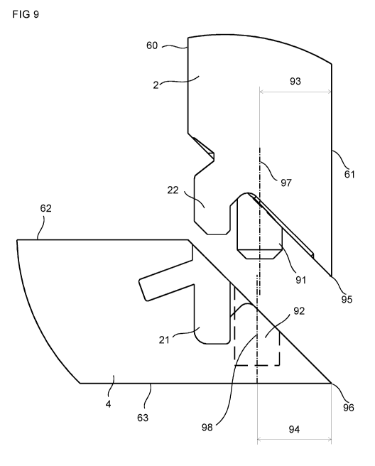
FIG 9 shows an enlargement of a corner part of an embodiment of the first
panel and
the second panel, without the flexible tongue, before assembling.
FIG 10 shows an enlargement of a corner part of an embodiment of the first
panel and
the second panel, without the flexible tongue, before assembling.
Detailed description
Specific embodiments of the invention now will be described with reference to
the
accompanying drawings. This invention may, however, be embodied in many
different
forms and should not be construed as limited to the embodiments set forth
herein;
rather, these embodiments are provided so that this disclosure will be
thorough and
complete, and will fully convey the scope of the invention to those skilled in
the art. The
terminology used in the detailed description of the embodiments illustrated in
the
accompanying drawings is not intended to be limiting of the invention. In the
drawings,
like numbers refer to like elements.
CA 03094060 2020-09-15
WO 2019/182505
PCT/SE2019/050259
An embodiment of an assembled product, such as a furniture product, comprising
panels joined together with mitre joints is shown in FIG 1.
Embodiments of the invention concern a set of panels, comprising a mechanical
locking
device, for an assembled product, such as illustrated in FIG 1 in a 3D view.
5 FIG 2 shows an embodiment including a set of panels comprising a first
panel 2 with a
first main plane and a second panel 4 with a second main plane. FIG 3 shows an
enlargement of the encircled area in FIG 2 without the flexible tongue. The
first panel
and the second panel are provided with a mechanical locking device for locking
a first
edge of the first panel 2 to a second edge of the second panel 4 at a junction
plane J.
The first main plane is essentially perpendicular to the second main plane and
the
junction plane is extending between the first main plane and the second main
plane.
The panels are shown in a locked position in a crosscut view. A longitudinal
direction of
the first edge and the second edge extends perpendicular to the view shown.
The first
edge comprises an edge tongue 22 that extends from the junction plane J. The
second
edge comprises an edge groove 21 at the junction plane, wherein the edge
tongue is
configured to cooperate with the edge groove for locking together the first
and the
second edges in a first direction D1 which is perpendicular to the first main
plane.
The edge tongue 22 comprises a tongue groove 10. The edge groove 21 comprises
a
flexible tongue 30 arranged in an insertion groove 20, said flexible tongue is
configured
to cooperate with the tongue groove 10 for locking together the first and the
second
edges in a second direction D2 which is perpendicular to the second main
plane.
The mechanical locking device may comprise a first space 46 between the edge
tongue
22 and the edge groove 21 at an opening of the edge groove 21 and at the
junction
plane in a locked position of the first and the second edge. The first space
46 may have
the advantage that a loading of a part of the second edge at the opening of
the edge
groove is avoided. This part of the second edge may be a weak part, since
little material
is available to absorb a load. The angle 74 between the junction plane and the
first main
plane may be about 45 . The edge tongue 22 preferably extends, from the
junction
plane, essentially in the second direction.
The first panel 2 has a first thickness 65 and the second panel 4 has a second
thickness
64. The first and the second thickness may be essentially the same. The first
panel 2
comprises an inner half 66, at a first side of a central plane 68 of the first
panel, and an
outer half 67, at second side of the central plane 68 of the first panel, in a
direction of
the thickness of the first panel. The entire edge tongue 22 is preferably at
the inner half
of the first panel. This may have the effect that more material is obtained
between the
CA 03094060 2020-09-15
WO 2019/182505
PCT/SE2019/050259
6
edge groove 21 and an outer corner, in a locked position of the first and the
second
panel, which may increase the strength of the mechanical locking device. The
first panel
comprises an inner face 60 and an outer face 61. The second panel comprises an
inner
face 62 and an outer face 63.
.. FIG 3 shows that a first side of the edge tongue 22 may comprise, at the
junction plane
J, a first locking surface 41, and the edge groove 21 may comprises, at the
junction
plane J, a second locking surface 40. The first locking surface and the second
locking
surface are essentially parallel and are configured to cooperate for locking
in the first
direction. The first locking surface and the second locking surface preferably
extend
.. essentially in the second direction. The edge tongue 22 at a second side,
which is
opposite the first side, may comprise a third locking surface 43 and the edge
groove 21
may comprise a fourth locking surface 42, wherein the third locking surface
and the
fourth locking surface are essentially parallel and are configured to
cooperate at a
distance from the junction plane for locking in the first direction. The third
locking
surface and the fourth locking surface are preferably extending essentially in
the second
direction. Said parallel first, second, third and fourth locking surface may
have the
advantage that panels are easy to assemble and that, e.g., a furniture
comprising said
set of panels may be more stable. The fourth locking surface 42 is preferably
closer to
the central plane 68 than the second locking surface 40.
The third locking surface 43 and the fourth locking surface 42 may cooperate,
to absorb
a load, at an area extending over a first distance 47 in the second direction.
The third
locking surface and the fourth locking surface are preferably displaced from
the junction
plane by a second distance 48. This may have the effect that more material is
obtained,
in the first direction D1, between the fourth locking surface 42 and the
junction plane,
which may increase the strength of the mechanical locking device. The first
distance 47
may be within the range of about 20% to about 200% of the second distance 48
or
within the range of about 50% to about 150% of the second distance 48. The
first 47
distance is essentially the same as the second distance 48 in the embodiment
shown in
FIG 3.
The first side of the edge tongue 22, at a distance from the junction plane,
may
comprise a fifth locking surface 45 and the edge groove 21 may comprise a
sixth locking
surface 44 at a distance from the junction plane J. The fifth locking surface
and the sixth
locking surface are essentially parallel and are preferably configured to
cooperate for
locking in the first direction. The fifth locking surface and the sixth
locking surface are
preferably extending essentially in the second direction. The insertion groove
20 is, in
the embodiment shown FIG 3, positioned between the sixth locking surface 44
and the
CA 03094060 2020-09-15
WO 2019/182505
PCT/SE2019/050259
7
second locking surface 40. The tongue groove 10 may be positioned between the
fifth
locking surface 45 and the first locking surface 41.
The first panel 2 and the second panel 4 are preferably configured to be
assembled by
displacing the first panel 2 relative the second panel 4 in the second
direction D2,
.. wherein the first panel is perpendicular to the second panel. The edge
tongue 22 is
inserted into the edge groove 21, wherein the flexible tongue 30 is pushed
back into the
insertion groove and springs back into the tongue groove 10 to obtain a locked
position.
The set of panels may be furniture panels.
The insertion groove 20 may extend along essentially the entire length of the
edge
groove.
FIG 5A shows panels 102, 104 that are joined with a mitre joint and FIG 5B
shows an
enlargement of the encircled area in FIG 5A. The panels 102, 104 may show a
gap 85
at the mitre joint at the front edges 81, 82 of the panels if one of the
panels has a curved
shape 86 along an edge at the mitre joint. The panels may have obtained the
curved
.. shape due to a load and, e.g., wood based panels may have obtained the
curved shape
due to a humidity change.
FIG 6A-C shows an embodiment of the first panel in a bottom view, in a side
view, and
in a 3D view, respectively. The embodiment of the first panel comprises an
embodiment
of the edge tongue 22 which extends along essentially the entire length of the
first edge
in a longitudinal direction of the first edge and ends at a front end 87 at a
distance from
a front edge 81 of the first panel 2. The dowel 91 may be positioned at
distance from the
front edge 81 of the first panel 2. The dowel 91 may be positioned between the
front end
87 of the edge tongue 22 and the front edge 81 of the first panel 2.
FIG 7A-C shows an embodiment of the second panel in a bottom view, in a side
view,
and in a 3D view, respectively. The edge groove 21 may extend along
essentially the
entire length of the second edge in a longitudinal direction of the second
edge and end
at a front end 88 at a distance from a front edge 82 of the second panel 4.
The dowel
groove 92 may be positioned at distance from the front edge 82 of the second
panel 4.
The dowel groove 92 may be positioned between the front end 88 of the edge
groove
21 and the front edge 82 of the second panel 4.
FIG 8 shows an embodiment of the first panel and the second panel locked
together
with an embodiment of the mechanical locking device and FIG 9 and 10 shows an
enlargement of a corner part of an embodiment of the first panel and the
second panel,
without the flexible tongue 30, before assembling.
CA 03094060 2020-09-15
WO 2019/182505
PCT/SE2019/050259
8
The embodiment shown in FIG 6-8 comprises a first panel with a first main
plane and a
second panel with a second main plane, wherein the first and the second panel
comprises a mechanical locking device which is configured for locking a first
edge of the
first panel 2 to a second edge of the second panel 4 at a junction plane J.
The first main
plane is essentially perpendicular to the second main plane and the junction
plane is
extending between the first main plane and the second main plane. The
mechanical
locking device comprises at the first edge an edge tongue 22 which extends
from the
junction plane J and at the second edge comprises an edge groove 21 at the
junction
plane. The edge tongue is configured to cooperate with the edge groove for
locking
together the first and the second edges in a first direction D1 which is
perpendicular to
the first main plane.
FIG 9 shows an embodiment of the mechanical locking device which comprises a
dowel
91 at the first edge and a dowel groove 92 at the second edge, wherein the
dowel 91 is
configured to cooperate with the dowel groove 92. A centreline 97 of the dowel
91 is
positioned at a first distance 93 in the first direction from an outer corner
95 of the first
panel 2. The dowel groove 92 is positioned at a second distance 94 in the
first direction
from an outer corner 96 of the second panel 4, and the second distance 94 is
greater
than the first distance 93.
A difference between the second distance 94 and the first distance 93 may be
within the
range of about 0,1mm to about 0,5mm, or is about 0,3mm.
FIG 10 shows an embodiment of the mechanical locking device which comprises a
dowel 91 at the first edge and a dowel groove 92 at the second edge. An outer
surface
105 of the dowel 91 is configured to cooperate with an outer surface 106 of
the dowel
groove 92. The outer surface 105 of the dowel 91 is positioned at a third
distance 107
in the first direction from an outer corner 95 of the first panel 2. The outer
surface 106 of
the dowel groove 92 is positioned at a fourth distance 108 in the first
direction from an
outer corner 96 of the second panel 4, and the fourth distance 108 is greater
than the
third distance 107.
The outer surface 105 of the dowel 91 may be parallel to the outer surface 61
of the first
panel 2.
The outer surface 105 of the dowel 91 may be the surface of the dowel which is
closest,
in the first direction, the outer corner 95 of the first panel 2.
The outer surface 106 of the dowel groove 92 may be perpendicular to the outer
surface
63 of the second panel 4.
CA 03094060 2020-09-15
WO 2019/182505
PCT/SE2019/050259
9
The outer surface 106 of the dowel groove 92 may be the surface of the dowel
groove
which is closest, in the first direction, the outer corner 96 of the second
panel 4.
A difference between the fourth distance 108 and the third distance 107 may be
within
the range of about 0,1mm to about 0,5mm, or is about 0,3mm
The dowel 91 may be attached to another dowel groove 99 at the first edge.
The dowel may be attached to the dowel groove 92 at the second edge before the
first 2
and the second 4 panels are assembled and locked together with the mechanical
locking device. Thus, the dowel is, in this embodiment, inserted in said
another dowel
groove 99, at the first edge, during the assembling.
The dowel 91 may be of a cylindrical shape. The diameter may be in the range
of about
5mm to about 8 mm.
The dowel groove 92 and/or the said another dowel groove 99 may be of an
essentially
cylindrical shape, such as a drill hole or a bottomed drill hole. The diameter
may be in
the range of about 5 mm to about 8 mm
The dowel 91 may be made from one or more of a wood based material, a polymer
material, preferably with a reinforcement, such as glass fibre or a metal.
The edge tongue 22 may formed of a core material of the first panel and or at
least
partly in a surface layer of the first panel. The edge groove 21 may be formed
of a core
material of the second panel and/or at least partly in a surface layer of the
second
panel. The edge tongue 22 may formed of material separate from the core
material of
the first panel. The edge groove 21 may be formed of a material separate from
the core
material of the second panel.
The edge tongue 22 may comprises a tongue groove 10 and the edge groove 21 may
comprise a flexible tongue 30, preferably arranged in an insertion groove 20,
and
wherein said flexible tongue is configured to cooperate with the tongue groove
10 for
locking together the first and the second edges in a second direction D2 which
is
perpendicular to the second main plane.
The angle between the junction plane and the first main plane may be about 45
.
The edge tongue 22 may extend, from the junction plane, essentially in the
second
direction.
The edge tongue 22 may extend along essentially the entire length of the first
edge in a
longitudinal direction of the first edge and ends at a distance from a front
edge 81 of the
first panel 2.
CA 03094060 2020-09-15
WO 2019/182505
PCT/SE2019/050259
The dowel 91 may be positioned between the front edge 81 of the first panel 2
and the
edge tongue 22.
The edge groove 21 may extend along essentially the entire length of the
second edge
in a longitudinal direction of the second edge and ends at a distance from a
front edge
5 82 of the second panel 4.
The flexible tongue 30 may be displaceable in the insertion groove.
The locking device is preferably configured such that the flexible tongue 30
moves out
of the tongue groove 10 when a tool is inserted into the tongue groove and
pushed back
into the insertion groove.
10 The insertion groove 20 may be parallel to the second main plane or at
an acute angle
75 to the second main plane, such that a bottom of the insertion groove 20 is
at a
greater distance from an inner face 62 of the second panel than an opening of
the
insertion groove to the edge groove.
The locking device may comprise a bevel or rounding at an opening of the
tongue
groove. This may facilitate disassembling as the bevel or the rounding may
prevent the
flexible tongue from getting stuck during the disassembling.
The set of panels as described above may be a part of an assembled furniture
product,
such as a corner of a frame. The tongue groove 10 may be open at a backside of
the
furniture, such that a tool may be inserted into the tongue groove to push
back the
flexible tongue 30 into the insertion groove 20 and unlock the locking device.
A core material of the first and the second panel may comprise a wood fibre
based
board, such as a HDF, MDF, plywood, solid wood or particleboard, or a
reinforced
plastic board or a wood fibre composite board. The core may be provided with a
decorative layer. Parts of the locking device may be formed, preferably by
mechanical
cutting, such as milling, of material of the first and the second panel.
An embodiment of the flexible tongue 30, which is displaceable in an insertion
groove
20, is shown in FIGS 4A-4D. FIGS 4A-4B show the flexible tongue 30 in a locked
potion
and FIGS 4C-4D show the flexible tongue 30 during assembling of the first
panel 2 and
the second panel 4. FIG 4B shows a cross section of the flexible tongue 30 in
FIG 4A.
FIG 4D shows a cross section of the flexile tongue 30 in FIG 4C. The flexible
tongue 30
comprises bendable protruding parts 24. A space 23 is provided between the
flexible
tongue 30 and a bottom wall of the insertion groove 20. FIG 4C shows that the
flexible
tongue 30 is pushed into the insertion groove 20 and towards the bottom wall
of the
insertion groove 20 during an assembly of the first panel 2 with the second
panel 4. The
CA 03094060 2020-09-15
WO 2019/182505
PCT/SE2019/050259
11
flexible tongue 30 springs back toward its initial position when the first
panel 2 and the
second panel 4 have reached a locked position. A recess 25 is preferably
arranged at
each bendable protruding part.
The flexible tongue 30 may have a first displacement surface 26 and an
opposite
second displacement surface 27, configured to be displaced along a third
displacement
surface 28 and a fourth displacement locking surface 29, respectively, of the
insertion
groove 20.
An alternative embodiment of the flexible tongue 30, without the protruding
bendable
parts 24, is shown in FIGS 4E-4F. FIG 4F shows a cross section of the flexible
tongue
.. 30 shown in FIG 4E. The alternative embodiment is bendable in its length
direction in
order to accomplish the same function as the embodiment shown in FIGS 4A-4D.