Note: Descriptions are shown in the official language in which they were submitted.
CA 03094144 2020-09-15
WO 2019/195245 PCT/US2019/025329
CONTROL FOR PARENT ROLL UNWINDING APPARATUS AND METHODS
RELATED APPLICATION DATA
This application claims the benefit of US provisional application ser. no.
62/652499, filed April 4, 2018, the disclosure of which is incorporated by
reference
herein.
BACKGROUND
Disclosed in more detail below is a control for a converting line. More in
particular, the disclosure is directed to aspects of a control for unwinding
the parent
roll and directing unwound web material to the converting line for additional
processing, and aspects of a control for controlling a driven roll in the
converting line
based upon tension sensed downstream of the driven roll.
In one aspect, the disclosure is directed to a method and apparatus for
estimating diameter and caliper of a web formed of one or more plies from an
unwinding parent roll. In another aspect, the disclosure is directed to a
method and
apparatus for web handling and converting line control based upon the
estimates of
parent roll diameter and unwinding web caliper. In another aspect, the
disclosure is
directed to a method and apparatus for web handling and converting line
control based
upon tension sensed downstream of the driven rolls.
As will become evident from the discussion that follows, the systems and
methods described herein allow converting machinery to be less complex to
operate,
reduce new converting line commissioning time, simplify product changeovers,
maximize uptime, and reduce cost. The systems and methods described herein
seek to
limit the effects of variability in substrate as it pertains to downstream
processes,
1
CA 03094144 2020-09-15
WO 2019/195245 PCT/US2019/025329
thereby allowing for optimizing uptime and minimizing operating intervention
while
increasing processing speeds.
The systems and methods disclosed herein allow for accurately driving and
optimize the timing of events in the unwind cycle that are dictated by unwind
diameter
or web position in the roll. One direct example of such optimization is a
parent roll
splice event. In order for the transients caused by such an event to be
minimized, one
must know the rate of change of diameter as it pertains to web output in order
to
predict pre-trigger events like line deceleration given variable running
speeds. There
are also many measurements and events recorded during the roll manufacturing
that
could be used to optimize the converting process if decoded accurately by
diameter.
Conventionally, these variabilities are manually handled by operators of the
equipment. Oftentimes, on the fly adjustments are made as the operator
observes the
process, or pre-programmed adjustments are made based on assumed criteria such
as
parent roll diameter. Generally, these methods all detract from overall
machine
efficiency because they either require operator time and interaction, or the
adjustments are based on general assumptions, which may be inapplicable for a
particular condition.
Using the systems and methods described herein, there may be opportunities
to capture data for enhanced converting line performance, production, and/or
raw
material utilization. Rather than developing new controls and measurement
techniques, the disclosure herein describes the use of existing or
conventional
converting line sensors to provide more accurate feedback and adaptive
controls that
may reduce operator interactions and other inefficiencies when using preset
conditions
guided by general assumptions.
2
CA 03094144 2020-09-15
WO 2019/195245 PCT/US2019/025329
DESCRIPTION OF THE DRAWINGS
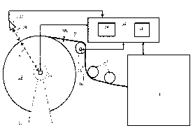
Figure 1 is a schematic diagram of an exemplary unwinder unwinding a web
from a parent roll for processing in a converting line and a sensor associated
with the
unwinder, a database receiving a signal from the sensor associated with the
unwinder
and signals from sensors associated with the converting line, and a controller
controlling operation of the converting line, the unwinder and web handling
equipment
between the unwinder and the converting line.
Figure 2 is a schematic diagram of a signature of a parent roll with an out-of-
round condition and associated sensor noise.
Figure 3 is a schematic diagram of a database structure associated with the
parent roll.
Figure 4 is a schematic diagram of an unwinder unwinding a web from a parent
roll and passing the web through web handling equipment prior to other
equipment in
the converting line with a conventional control configuration.
Figures 5A and 5B are schematic diagrams of a conventional control
configuration for web handling equipment between an unwinder and other
equipment
in the converting line as shown in Figure 4.
Figure 6 is a schematic diagram of an unwinder unwinding a web from a parent
roll and passing the web through web handling equipment prior to other
equipment in
the converting line with a modified control configuration.
Figures 7A and 7B are schematic diagrams of a modified control configuration
for web handling equipment between an unwinder and other equipment in the
converting line as shown in Figure 6.
3
CA 03094144 2020-09-15
WO 2019/195245 PCT/US2019/025329
Figure 8 is a plot showing the differences in relative tension (y axis) in the
web
over time (x axis) for certain web handling elements shown in Figure 4.
Figure 9 is a plot showing the differences in relative tension (y axis) in the
web
over time (x axis) for certain web handling elements shown in Figure 6.
Figure 10 is a plot showing the differences in relative tension (y axis) in
the web
over time (x axis) for certain web handling elements shown in Figure 4 with a
web
having a 15% higher modulus of elasticity than the web shown in Figure 8.
Figure 11 is a plot showing the differences in relative tension (y axis) in
the web
over time (x axis) for certain web handling elements shown in Figure 6 with a
web
having a 15% higher modulus of elasticity than the web shown in Figure 9.
DETAILED DESCRIPTION
As will be discussed in greater detail below, parent roll diameter and web
caliper may be used to optimize process set points in the converting
processing line, for
instance, nip, tension and log firmness in rewinding equipment. The rate of
change or
percentage of change of web caliper may also be used to fine tune parameters,
optimize the operating speed of the equipment, and minimize waste.
Additionally, rate
of change of diameter of the parent roll in addition to web caliper may be
used to
predict and prepare for upcoming events like marked splices.
Referring to Figure 1, a center driven unwinder 10 delivers a web of material
W
to other equipment 12 in the converting line through web handling rolls 14,
which may
include one or more rolls 16 with associated drives 18. The unwinder 10 has a
drive 20
and at least one sensor 22 positioned relative to the unwinder to measure
distance 24
between the sensor and a parent roll 26 loaded in the unwinder. A controller
30
controlling operation of the converting line and a database 32 accessible by
the
4
CA 03094144 2020-09-15
WO 2019/195245
PCT/US2019/025329
controller is provided. The center driven unwinder 10 may utilize existing
diameter
sensors 22 to develop diameter and caliper measurements during the unwind
process.
For instance, the sensors 22 may use laser time-of-flight technology to
calculate the
distance 24 from the sensor to the surface of the parent roll 26, thereby
effectively
measuring the radius R of the parent roll, and after successive revolutions,
measuring
the difference in radius of the parent roll to estimate sheet caliper WC. One
sensor
currently in use is a Banner LTF12UC2LDQ. Such a sensor has proven
satisfactory to
measure parent roll radius R during unwinding and provide an estimation of
caliper
WC.
A typical parent roll signature is shown in Figure 2 along with sensor noise.
Because the measured surface of the parent roll is typically not uniformly
round, the
measurement comprising the difference in parent roll radius R or the caliper
WC
estimate may be subjected to a square root least squares regression model in
the form
of Vbx + C . The measurements of parent roll radius R may be sampled
continuously
from multiple sensors 22 located about the parent roll 26 during the unwind
process.
The data may be collected continuously and transmitted to a processor 34 of
the
controller 30 of the converting line. The processor 34 may access the database
32 to
store data representative of diameter and caliper in the database. The
processor 34
may be further configured to perform regression analysis on the data. For
instance,
the processor may use a regression model that may continuously update the
coefficient (b) and constant (C) as a function of the amount of web material
delivered
from the unwinder 10. The data to be analyzed may be stored in a first in
first out
(FIFO) database stack, allowing for a continuously adapting fit of the recent
history of
the running parent roll. It is known that the caliper WC of the web material W
of the
5
CA 03094144 2020-09-15
WO 2019/195245 PCT/US2019/025329
parent roll changes throughout the parent roll and is not consistent
throughout the
parent roll. Generally speaking, changes in the caliper of the web material
typically
occur gradually due to the nature of the substrate manufacturing process and
rewinding process. With this in mind, for a particular substrate and
converting process,
the size of the FIFO database stack and sample interval may be adjusted as
necessary
taking into account also the accuracy of the sensor(s) 22 and the need to
identify the
data signifying a change of the caliper WC. The sample interval may also be
randomized within a range so as to minimize the potential of sample aliasing
of the
non-uniform shape of the parent roll. A digital filter may also be employed to
remove
out of band noise from any signals prior to generating the data stored in the
FIFO
database. Once the data is fit, the derivative of the regression equation can
be
evaluated.
It has been determined that an adequate function for the regression analysis
. b
is¨,_. The method has been proven useful in describing the rate of change of
2vbx+C
diameter (2xR) per amount of web delivered. At a given location on the
circumference
of the parent roll 26, the change in diameter (A(2xR )) in one revolution of
the parent
roll effectively equates to two times the caliper at unwinding. The final form
leverages
the regression value for diameter at the discrete time of sampling such that
caliper =
(2 b)Fc)(7rA/bx+C) irb
_________________________________ which simplifies to ¨.
2 4
The above analysis to develop estimates of caliper WC during sampling
intervals
during the unwind process may be utilized in several ways to enhance the
converting
process. Diameter (2xR ) and caliper WC data may be used by the control to
effectuate
real-time control of downstream equipment in the converting line, such as a
rewinder.
6
CA 03094144 2020-09-15
WO 2019/195245 PCT/US2019/025329
Generally speaking, large diameter parent rolls of structured web material
exhibit
decreasing unwinding caliper and higher in-wound stress during unwinding. As
the
finished diameter of a structured sheet parent roll 16 increases, the winding
profile and
the effects of overwrapped sheets and roll weight have an increasing effect on
the
inner wound properties and subsequently how the unwound web material behaves
through the converting processes. By monitoring for changes in caliper WC and
diameter (2xR) as the parent roll unwinds, the downstream web handling and
processing equipment may be adjusted as needed to enhance line efficiency. As
will be
discussed in greater detail below, the tension of the web (e.g., between
rollers and
load cells) may be trimmed accurately in view of a given web condition. Other
processes involving lamination and/or embossing equipment may be more tightly
controlled, for instance, web speeds, nips pressure and spacing, embossing
roll speed
and adhesive application. Converting processes may also be automatically
adjusted to
maximize machine throughput. Some specific examples of potential adjustments
include increasing the embossing level, decreasing the applicator to steel
roll gap,
relaxing the web more as the roll unwinds (profiled unwinding/traversal
tensions based
on unwinding caliper trend versus diameter) and various rewinder adjustments
to
maximize wound bulk, for instance, lower roll speed offset.
Additionally, diameter (2xR) and unwinding caliper WC measurements may be
correlated to processing information associated with the winding of the parent
roll to
increase the effectiveness of the controller 30. For instance, defects
detected during
the process of forming the parent roll 26, for instance, during the winding
process or
during the production of the web W which is wound to form the parent roll, may
be
tracked relative to diameter (2xR) and caliper WC during winding of the parent
roll.
7
CA 03094144 2020-09-15
WO 2019/195245 PCT/US2019/025329
The data may be collected and maintained with the parent roll 26. The data may
be
representative of parent roll production parameters, such as process time,
amount of
web material wound, caliper, diameter, the nature of the defect, location of
the defect,
size of the defect (in terms of a dimension in a direction of the web movement
and a
.. dimension in a direction transverse to the web movement), and/or severity
of the
defect. An example of parent roll data which may be stored with the parent
roll 26
and uploaded to the database 32 is shown in Figure 3. This roll specific data
representative of the manufacturing and upstream winding of the parent roll 26
prior
to delivery to the converting line may also be uploaded into the database 32
and
correlated with the unwinding process parameters. When the parent roll 26 is
queued
for use in a converting process, the parent roll production data may be
uploaded to the
database 32 associated with the unwinder and converting equipment. The roll
specific
data associated with the manufacturing and/or winding of the parent roll
(prior to
unwinding) may be synchronized with the diameter (2R) and caliper WC
measurements
during the unwinding process to maximize the effectiveness of the controls for
the
converting line. Thus, the relative condition of the web as it unwound can be
predicted based upon measurements of diameter, caliper and change in caliper
during
the unwind process, and appropriate proactive action can be effected through
the
controller to control converting equipment and the unwinder, as necessary. For
instance, a certain known defect in the parent roll production occurring at a
specific
time, diameter, or caliper, can be tracked relative to the unwind process so
that the
converting line equipment and unwinder may be operated in a manner to minimize
the
effects of the defect. The measurement of diameter, caliper and rate of change
of
caliper during the unwind process can be used to predict such defects in the
parent
8
CA 03094144 2020-09-15
WO 2019/195245 PCT/US2019/025329
roll. As a further example, in a rewinder operation, as the bulk or modulus of
the
wound log changes, the controls of the converting line may be configured to
change
converting line handling processes to maintain a more stable operation. The
roll
specific data and/or data representative of process parameters including
diameter and
caliper may indicate with probability the existence of a defect in the unwound
web of
the parent. Depending upon the severity of the defect, the control may be
configured
to control operation of the converting line accordingly. For instance, for a
severe
defect, the control may control the converting line to decrease running speed
automatically and then resume speed once the defect condition passes. This
might
reduce the potential for web break events associated with known defects,
thereby
reducing waste.
Additionally, having accurate information of the winding of the original
parent
roll allows the converting line controls to more accurately estimate
processing events
as the parent roll unwinds, including time before roll splice. An automated
control may
allow the machine to automatically splice over to a new parent roll, thereby
eliminating
or reducing the requirements for a line operator to manually to perform
operations
associated with splicing.
Many converting line process events are based on the unwind roll diameter.
For instance, web splicing of expired unwind rolls with new unwind rolls
includes
several events that must be timed and staged in order to maximize the
efficiency.
Movement of the splice mechanism into a preferred splice position just prior
to splicing
allows for reliability of the splicing sequence and maintains ease of
operation. The
splice event requires accurate measurements of roll diameter where the
splicing occurs
at a known or preset diameter of the unwinding roll. Estimating unwinding
caliper
9
CA 03094144 2020-09-15
WO 2019/195245
PCT/US2019/025329
using the methodology described above provides consistent accurate estimates
of roll
diameter. Thus, the unwind process may allow for the parent roll to be
consistently
unwound to a level that minimizes spent roll waste, and allows for less
variability and
thus easier handling of spent rolls.
Further, accurate estimation of time prior to processing events is useful in
simplifying the operator experience. The accurate estimation of time prior to
processing events provides for generation of a prioritized task list of
upcoming critical
processing events that will require operator intervention or attention. With
an
accurate estimate of the rate of diameter reduction of the parent roll during
the
unwind process, amount of web material unwound, a valid estimate of time to an
event, for instance, a splice/expired roll removal event, can be provided to a
priority
estimation system.
Further, accurate estimation of unwinding caliper and unwinding caliper
changes can be related to effective changes in wound log in-wound compression,
which allows for relating a relative change in firmness of the finished log as
the input
material changes. Parameters such as unwinding caliper, unwinding caliper
changes,
rewinder wound log in-wound compression, and estimated rewinder log firmness
can
be tracked and transmitted to downstream processes such as tail sealing (roll
height
adjustments), saw cutting (clamps), and packaging equipment to proactively
adjust for
incoming product changes thereby maximizing efficiency of the converting line
and
optimizing product quality.
Tracking the general trend of roll unwinding caliper versus diameter provides
insight into the raw material, the winding process to produce the parent roll,
and how
the parent roll will behave in the converting process. It may be desirable to
track such
CA 03094144 2020-09-15
WO 2019/195245
PCT/US2019/025329
information over time by parent roll product part number or SKU, and monitor
for
parent rolls that exceed a band of historical data. Such information could
result in a
proactive alert for operator action, or automatic converting line controller
action for
instance, reducing speed, reducing line tension, nip adjustment, etc. Such
information
may also be used to associate unwinding characteristics with net converting
line
machine performance and other parameter adjustments to generate machine
learning
data sets and adaptive controls to further automate converting line controller
action.
Accordingly, the parent roll diameter and caliper may be measured when a
defect is
detected in the web from downstream equipment in the converting line, e.g., a
machine vision system associated with the rewinder. The nature of the defect
and
other desirable process measurements may be captured and stored in a database
to
form a defect database, such as that mentioned earlier and by way of example
as
shown in Figure 3. The parent roll manufacturing history including its wind
history may
be accessed from the parent roll supplier and correlated to the unwind history
and
defect database. The controller for the converting process may be configured
to make
adjustments to the converting line equipment based upon the data in the defect
database.
As a further example, accurate estimation of diameter, unwinding caliper and
unwinding caliper changes can be used in connection with controls for
downstream
web handling equipment including the successive rolls involved in directing
the
unwinding web to a rewinder. As will be described below in greater detail,
accurate
estimation of diameter, unwinding caliper and unwinding caliper changes can be
used
to reduce problems in web handling, maintaining web stability, and minimizing
web
stress as the web is unwound and conveyed. Popular web manufacturing processes
11
CA 03094144 2020-09-15
WO 2019/195245 PCT/US2019/025329
such as TAD, NTT, QRT, and other structured or textured formats are
exceptionally
sensitive to not only peak stress, but duration of stress - often more so than
webs
produced with conventional dry crepe manufacturing processes. Any increase in
web
stress is generally detrimental to the behavior in downstream processes such
as
rewinding, and, therefore, it is desirable to minimize the stress applied to
the web.
Figure 4 shows a conventional configuration of web handling equipment
between the unwinder and the converting line, and Figures 5A and 5B show a
typical
control for the conventional configuration of Figure 4. In conventional
configuration,
the parent roll 40 is driven with a drive 42, and the unwinding web W will
pass from the
.. parent roll 40 to a first downstream roll 52 with a load cell 54 and then
to a second roll
56 and a third roll 58. The second roll 56 may be a driven roll with a drive
60. In the
conventional configuration, the unwinder drive 42 is trimmed by tension
feedback
generated by the load cell 54 associated with the first downstream guide roll
52, or
located at another location between the unwinder payoff point and the first
downstream guide roll. Typically, there may also be another tension control
zone
trimmed by roll n, measured at roll n+1. The speed reference for all rolls is
a common
master reference with a trim offset for each roll to account for the relative
spans
between the rolls. These speed trim offsets may or may not cascade from roll
to roll.
In situations where a speed offset does not cascade, the adjustment will
affect multiple
spans. In situations where an adjustment cascades (back towards the unwinding
parent roll in this scenario), the adjustment will maintain the same relative
speed
differential in the spans behind the adjustment. For instance, the payoff web
tension
may be measured by the load cell associated with roll 1. The web tension may
be
controlled by changing the speed of the driven parent roll. This loop attempts
to
12
CA 03094144 2020-09-15
WO 2019/195245 PCT/US2019/025329
control the tension in the span between the parent roll payoff point and the
first driven
roll 52. Downstream of the second downstream guide roll 56 can be a number of
idling
and driven web handling elements 64,65,66,67.
In this conventional configuration of Figures 4 and 5A and 5B, the
perturbations
introduced by non-uniformities in the parent roll radius (out-of-roundness)
not only
result in local disturbances in the span between the parent roll and the first
downstream guide roll 52 and between the first downstream guide roll and the
second
downstream guide roll 56, but, as the web travels downstream, these
disturbances set
up conditions that create even greater instabilities. For instance, each span
of web and
associated rollers can enter resonance and eventually a state of stick-slip
oscillation as
the conveyed web stress crosses various thresholds. The net result of this
scenario is
an unstable web that has very high peak stress with behavior that is highly
variable
based on web modulus, strain recovery rate, coefficient of friction of
substrate on web
elements, running tension, speed, etc.
A conventional closed loop tension feedback scheme such as that shown in
Figures 5A and 5B tends to be insufficient. Maintaining response stability
under
changing input conditions generally results in an under-tuned system which
further
exacerbates the problem. In such a system, web spans may experience
significant
swings in tension, for example, on one extreme the load cell will measure no
load as
the load cell roll loses wrap/contact with the web and another extreme where
the web
tension is above the maximum threshold measurable by the load cell. If not
properly
tuned, closed loop tension feedback schemes can contribute to the peak
stresses and
lack of general controllability. If a dancer is used in place of a load cell,
the frequency
of the disturbance will increase as web speed increases, and, at some point,
the dancer
13
CA 03094144 2020-09-15
WO 2019/195245 PCT/US2019/025329
will effectively lose the ability to provide useful feedback. In conventional
systems to
counter this behavior, the control may be configured to increase the tension
in the web
as it is conveyed such that the troughs of web stress do not dip below the
minimum
amount required for maintaining traction on the rotating web elements. This
results in
significant web conveyance stresses and sheet degradation.
Figure 6 shows a modified configuration of web handling equipment between
the unwinder and the converting line, and Figures 7A and 7B show a control for
the
modified configuration of Figure 6. In a modified configuration, disturbances
introduced at the unwinder payout point from the parent roll may be reduced
and
attenuated to prevent downstream propagation, which thus improves the
converting
processing line machine efficiency, maintains more of the web's native
characteristics,
and improves finished product quality. Some measurable characteristics
include: sheet
tension and caliper, and wound product characteristics some of which influence
ultimate wind speed.
Referring to Figure 6, in the modified configuration, the first downstream
roll 70
is arranged as a driven, high traction roll, and is followed by second, third
and fourth
downstream rolls 72,74,76. The high traction of the roll can be provided by,
for
example, a tungsten carbide coating, a plasma coating, or a covering of safety
walk
tape. Coatings are available from, for example, Praxair, Racine Flame Spray,
and
American Roller. Safety walk tape is available from, for example, 3M. The
first
downstream roll 70 may be configured to operate to balance the outgoing web
velocity
and upstream span strain. One embodiment of the controller may be to configure
the
controller with a control loop for the first downstream roll 70 that subtracts
baseline
components (losses, acceleration torque) and operates at a target output of
torque
14
CA 03094144 2020-09-15
WO 2019/195245 PCT/US2019/025329
that relates directly to force imparted on the web W. The first downstream
roll 70 may
be configured to maintain a standard velocity/position loop configuration to
generate
the baseline command for the target torque output with the above loop trimming
that
to achieve the desired web force while damping the relative band of velocity
trim
based on the sheet modulus and tensile properties. The unwind drive 42 may be
trimmed by tension feedback located on a load cell 78 downstream from the
unwinding process, for instance, adjacent to the fourth downstream roll 76.
There may
be another tension control zone trimmed by the sixth downstream roll 80, or
another
further downstream roll. The feedback tension load cell 82 may be located a
number
of rolls downstream. In another embodiment of the controller, the controller
may use
the hardware's native loops and be configured to use appropriate feedforward
signals
to compensate for roll inertia and commanded dynamics. The velocity (and
optionally
position) loops may be (de)tuned to be behave as over-damped, which may
prevent
the driven roll 1 from exciting secondary resonances and high peak stress
(rapid torque
rise) while still providing a more uniform web payout.
In the modified scheme, after the first downstream drive roll 70, depending on
application requirements, a load cell roll or other web handling elements may
be
placed 64. As shown in Figure 6, the modified configuration may provide for
the third
downstream roll 74 to be a second driven roll, and may provide for the second
downstream roll 72 to be a spreader roll. The second driven roll and the
spreader roll
may be provided upstream and prior to the load cell roll, which may be the
fourth
downstream roll 76. The effect of the spreader roll 72 will be optimized due
to an
already damped web span ¨ this allows for consistent roll contact and a more
uniform
strain in the sheet as it traverses the roll. By the time the web reaches the
fourth
CA 03094144 2020-09-15
WO 2019/195245 PCT/US2019/025329
downstream roll 76, the effect of the first downstream roll 70 normalizing
velocity
along with the web's natural viscoelasticity will significantly damp the
disturbance in
the web. This results in more stable and lower noise tension feedback. This
signal may
then be used to trim the unwind speed directly. All driven guide rolls
70,74,80 follow a
nominal master speed reference, that is, they do not vary with the unwind
tension
feedback or, in the case of a center driven roll, the diameter feedback of the
parent
roll.
Figures 8-11 show simulations of the conventional configuration (Figs. 4, 5A,
5B)
and the modified configuration (Figs. 6, 7A, 7B). The components of the two
configurations are identical with only the location of the load cell changed
as described
above, along with some slight damping of the response of the first driven roll
after the
unwind in the modified configuration. The parent roll is modeled with an "egg
shaped"
defect common with rolls stored on their sides and stacked for instance as
shown in
Figure 2. The plot starts at a steady state condition running at 700 MPM and
ends with
a deceleration to a stop. The differences between the conventional and
modified
configuration are shown in the plots of Figures 8-11. In Figures 8 and 10, the
plot
shows tension (y axis) in relation to time (x axis) for the conventional
configuration for
the unwinder 40 (¨), the first driven roll 52 (---), the third downstream roll
58 (""), and
the sixth downstream roll 66(-'-). In Figures 9 and 11, the plot shows tension
(y axis) in
relation to time (x axis) for the modified configuration for the unwinder 40
(¨), the
third downstream roll 74 (----), and the sixth downstream roll 80(¨). The
initial web
span in the conventional configuration runs (Figs. 8 & 10) have higher peak to
peak
amplitudes than the modified configuration runs (Figs. 9 &11), and the
downstream
spans in the conventional configuration runs (Figs. 8 & 10) do not attenuate
as quickly
16
CA 03094144 2020-09-15
WO 2019/195245
PCT/US2019/025329
as in the modified configuration runs (Figs. 9 & 11). There is also
significantly more
noise in the conventional configuration runs (Figs. 8 & 10) during the
deceleration as
the roll velocities and web span tensions oscillate. The sensitivity to
substrate
variability is also illustrated by the second set of runs (Figs. 10 and 11)
where a single
property (machine direction modulus of elasticity) was increased by 15%. Such
a web
being processed under the conventional configuration would experience
difficulties
during processing because of the high peak to peak amplitudes as shown in
Figure 10.
Figure 11 shows the same web being processed under the modified configuration,
which shows a more nominal behavior.
The two examples above are illustrative of the generalized improvement that
the modified scheme provides in the consistency, robustness, controllability,
and
reductions in peak web stress. These are critical requirements in effectively
handling
and preserving web when high speed and efficiency in converting are desired.
The
modified configuration provides a result where the sheet maintains more
desirable
qualities which facilitate downstream process efficiency and end product
quality. The
modified configuration process tends to be more robust from unwinding through
downstream processes and reduces operator intervention. The improved control
may
also allow for reducing the complexity of downstream web handling equipment
and
controls, which could include longer spans, fewer driven guide rolls and fewer
edge
control implements.
Further embodiments can be envisioned by one of ordinary skill in the art
after
reading this disclosure. In other embodiments, combinations or sub-
combinations of
the above-disclosed invention can be advantageously made. The example
arrangements of components are shown for purposes of illustration and it
should be
17
CA 03094144 2020-09-15
WO 2019/195245 PCT/US2019/025329
understood that combinations, additions, re-arrangements, and the like are
contemplated in alternative embodiments of the present invention. Thus,
various
modifications and changes may be made thereunto without departing from the
broader spirit and scope of the invention as set forth in the claims and that
the
invention is intended to cover all modifications and equivalents within the
scope of the
following claims.
18