Language selection

Search

Patent 3094230 Summary

Third-party information liability

Some of the information on this Web page has been provided by external sources. The Government of Canada is not responsible for the accuracy, reliability or currency of the information supplied by external sources. Users wishing to rely upon this information should consult directly with the source of the information. Content provided by external sources is not subject to official languages, privacy and accessibility requirements.

Claims and Abstract availability

Any discrepancies in the text and image of the Claims and Abstract are due to differing posting times. Text of the Claims and Abstract are posted:

  • At the time the application is open to public inspection;
  • At the time of issue of the patent (grant).
(12) Patent Application: (11) CA 3094230
(54) English Title: ORGANIC SOIL BASED AUTOMATED GROWING ENCLOSURE
(54) French Title: ENCEINTE DE CULTURE AUTOMATISEE A BASE DE SOL BIOLOGIQUE
Status: Compliant
Bibliographic Data
(51) International Patent Classification (IPC):
  • A01G 9/02 (2018.01)
  • A01G 9/029 (2018.01)
  • A01G 31/02 (2006.01)
  • A01G 31/06 (2006.01)
(72) Inventors :
  • OTTERMAN, GARY (United States of America)
(73) Owners :
  • SURELEAF, LLC (United States of America)
(71) Applicants :
  • SURELEAF, LLC (United States of America)
(74) Agent: PERRY + CURRIER
(74) Associate agent:
(45) Issued:
(86) PCT Filing Date: 2019-01-11
(87) Open to Public Inspection: 2019-07-18
Availability of licence: N/A
(25) Language of filing: English

Patent Cooperation Treaty (PCT): Yes
(86) PCT Filing Number: PCT/US2019/013336
(87) International Publication Number: WO2019/140289
(85) National Entry: 2020-07-10

(30) Application Priority Data:
Application No. Country/Territory Date
62/617,538 United States of America 2018-01-15

Abstracts

English Abstract


An automated organic closed-loop grow enclosure that has rows of hydration
trays that support removable (three across)
grow containers for microgreens such as broccoli. Each grow container has a
layer of soil. The seeds are treated with mycorrhizae and
mixed with enriched top soil having a wicking agent. The grow containers are
automatically watered once a day from the bottom and
the capillary action of the soil lifts and holds the water in the grow
container. LED Lighting is used to stimulate day and night cycles.
The water is treated with magnets, turbulence and charcoal filters. The water
cascades down the tiered trays using siphons. No other
treatment of the water is necessary since almost no micro-organisms or organic
material leak from the grow containers due to a filter
barrier in the bottom of the grow container. Spectacular consistent growth
rates are easily achieved.


French Abstract

L'invention concerne une enceinte de culture en boucle fermée biologique automatisée qui comporte des rangées de plateaux d'hydratation qui supportent des récipients de culture amovibles (par trois de face) pour des jeunes pousses telles que de brocoli. Chaque récipient de culture comporte une couche de sol. Les graines sont traitées avec des mycorhizes et mélangées avec de la terre végétale enrichie ayant un agent de méchage. Les récipients de culture sont arrosés automatiquement une fois par jour par le fond et l'action capillaire du sol élève et maintient l'eau dans le récipient de culture. Un éclairage à DEL est utilisé pour stimuler des cycles jour/nuit. L'eau est traitée à l'aide d'aimants, de turbulences et de filtres à charbon. L'eau descend en cascade les plateaux étagés à l'aide de siphons. Aucun autre traitement de l'eau n'est nécessaire étant donné qu'il n'y a pratiquement pas de micro-organismes ni de fuite de matière organique à partir des récipients de culture en raison d'une barrière de filtre dans le fond du récipient de culture. Des taux de croissance constants spectaculaires sont facilement obtenus.

Claims

Note: Claims are shown in the official language in which they were submitted.


VI. CLAIMS
I claim:

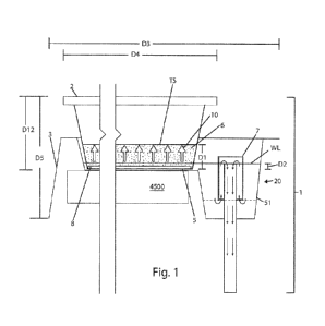
1. An apparatus, comprising:
a grow container having a grow container side wall joined to a grow container
bottom
having a plurality of aperture elements open between an internal surface and
an external surface
of said grow container bottom; and
a hydration barrier disposed over said internal surface of said grow container
bottom.
2. The apparatus of claim 1, wherein said hydration barrier comprises a
paper filter.
3. The apparatus of claim 2, wherein said hydration barrier comprises a
paper towel.
4. The apparatus of claim 3, wherein said hydration barrier comprises a two
ply paper towel.
5. The apparatus of claim 1, wherein said grow container bottom extends to
a grow container
bottom periphery bounding a grow container bottom area, said plurality of
aperture elements open
between an internal surface and an external surface of said grow container
bottom to define a
grow container bottom open area in said grow container bottom of about 1%.
6. The apparatus of claim 5, wherein said aperture elements have a
substantially even
distribution over said grow container bottom.
7. The apparatus of claim 6, wherein said aperture elements have a diameter
of about 6.0
mm.
8. The apparatus of claim 1, further comprising a hydration container
having a hydration
container side wall joined to a hydration container bottom defining an
internal surface and an
external surface, said internal surface defining an interior space configured
to receive said grow
container, said hydration container including at least one aperture element
open between said
internal surface and an external surface of said hydration container.
9. The apparatus of claim 8, further comprising a hydration liquid
recycling system operable
to deliver a hydration liquid from a hydration liquid source to said hydration
container and return
said hydration liquid passing through said at least one aperture in said
hydration container to said
liquid source.
10. The apparatus of claim 9, wherein said hydration liquid comprises
water.


11. The apparatus of claim 9, wherein said hydration liquid recycling
system includes a pump,
said pump capable of moving said hydration liquid in said liquid recycling
system.
12. The apparatus of claim 11, wherein a hydration liquid volume in said
hydration liquid
recycling system recirculated at a rate of about 12 times per hour.
13. The apparatus of claim 12, wherein said hydration liquid volume
comprises about 10
gallons.
14. The apparatus of claim 9, further comprising one or more filter
elements removably
coupled to said liquid recycling system, wherein said one or more filters
filter said hydration
liquid recirculated in said liquid recycling system.
15. The apparatus of claim 14, wherein said one or more filter elements
comprises a filter
sock having a porosity of about 100 micrometers.
16. The apparatus of claim14, wherein said one or more filter elements
comprises activated
carbon pellets.
17. The apparatus of claim 9, further comprising one or more pairs of
magnets, each of said
one or more pairs of magnets disposed in oppositional, like polarity relation,
wherein said
hydration liquid passes between said one or more pairs of magnets.
18. The apparatus of claim 17, further comprising a series of spheres,
wherein said hydration
liquid passes about said series of spheres.
19. The apparatus of claim 9, wherein said hydration container comprises a
plurality of
hydration containers, said plurality of hydration containers arranged
vertically between a top
hydration container and a bottom hydration container.
20. The apparatus of claim 19, wherein said hydration liquid recycling
system delivers
hydration liquid to said top hydration container, and returns said hydration
liquid passing through
said aperture element of said bottom hydration container to said hydration
liquid source.
21. The apparatus of claim 1, further comprising a soil layer disposed
within said grow
container.
22. The apparatus of claim 21, wherein said soil layer further comprises
one or more of:
microorganisms, decomposing organic matter, peat moss, and coconut coir.

16


23. The apparatus of claim 21, further comprising a mineral layer disposed
on said soil layer.
24. The apparatus of claim 21, further comprising a plurality of seeds
disposed on said soil
layer.
25. The apparatus of claim 24, wherein said plurality of seeds soak in a
germination container
containing Mycorrhizal fungi admixed with said hydration liquid prior to being
disposed on said
soil layer.
26. The apparatus of claim 21, wherein said soil layer has a depth X.
27. The apparatus of claim 26, wherein said hydration liquid recycling
system delivers said
hydration liquid to said hydration container to hydrate said soil layer with
said hydration liquid
to a height of about one half of said depth X of said soil layer.
28. The apparatus of claim 27, wherein said depth X comprises about 20 mm.
29. The apparatus of claim 28, wherein said height of said soil layer
hydrated with said
hydration liquid comprises about 10 mm.
30. The apparatus of claim 27, wherein said soil layer wicks said hydration
liquid through
said plurality of aperture elements of said grow container.
31. The apparatus of claim 39, wherein said liquid recycling system drains
said liquid from
said soil layer hydrated with said hydration liquid at said height of about
one half of said depth
X of said soil layer to maintain said mineral layer on top of said soil layer.
32. The apparatus of claim 1, wherein porosity of said hydration barrier
retards passage of
said liquid through said hydration barrier.
33. The apparatus of claim 1, wherein porosity of said hydration barrier
precludes passage of
soil layer constituents or mineral layer constituents through said hydration
barrier.
34. The apparatus of claim 1, wherein porosity of said hydration barrier
filters
microorganisms from liquid passing through said hydration barrier.
35. The apparatus of claim 1, wherein porosity of said hydration barrier
prevents passage of
microorganisms through said hydration barrier.

17


36. The apparatus of claim 19, further comprising an enclosure having an
enclosure side wall
joining an enclosure top and an enclosure bottom defining an enclosure
interior space adapted to
receive said plurality of hydration containers.
37. The apparatus of claim 36, further comprising one or more hydration
container support
elements coupled to said enclosure side wall in said enclosure interior space,
said one or more
hydration containers disposed on said one or more hydration container support
elements.
38. The apparatus of claim 37, further comprising one or more fans coupled
to said enclosure.
39. The apparatus of claim 38, further comprising one or more light
emitting elements
coupled to said enclosure.
40. The apparatus of claim 39, further comprising a controller including a
processor
communicatively coupled to a non-transitory memory element, said memory
element containing
a controller program, said controller electronically coupled to one or more
of: said pump, said
one or more fans, and said one or more light emitting elements.
41. The apparatus of claim 40, wherein said program executable to activate
said pump to
operate during a pre-selected time duration.
42. The apparatus of claim 41, wherein said program further executable to
activate said pump
to operate during pre-selected cyclic time durations.
43. The apparatus of claim 40, wherein said program executable to activate
said one or more
fans during a pre-selected time duration.
44. The apparatus of claim 43, wherein said program executable to activate
said one or more
fans during pre-selected cyclic time durations.
45. The apparatus of claim 40, wherein said program executable to activate
said one or more
light emitting elements during a preselected time duration.
46. The apparatus of claim 45, wherein said program executable to activate
said one or more
light emitting elements during pre-selected cyclic time durations.
47. A method, comprising:
forming a grow container having a grow container bottom joined to grow
container
sidewall;

18


disposing a plurality of aperture elements in said grow container bottom, said
plurality of
aperture elements open between an internal surface and an external surface of
said grow container
bottom; and
disposing a hydration barrier over said internal surface of said grow
container bottom to
cover said plurality of aperture elements.
48. The method of claim 47, wherein said hydration barrier comprises a
paper filter.
49. The method of claim 47, wherein said hydration barrier comprises a
paper towel.
50. The method of claim 47, wherein said hydration barrier comprises a two
ply paper towel.
51. The method of claim 47, further comprising extending said grow
container bottom to a
grow container periphery bounding a grow container bottom area, said plurality
of aperture
elements open between an internal surface and an external surface of said grow
container bottom
define a grow container bottom open area in said grow container bottom of
about 1%.
52. The method of claim 51, further comprising substantially evenly
distributing said aperture
elements over said grow container bottom.
53. The method of claim 52, wherein said aperture elements have a diameter
of about 6.0 mm.
54. The method of claim 47, further comprising forming a hydration
container having a
hydrations container bottom joined to a hydration container sidewall, said
hydration container
having hydration container internal surface defining an interior space adapted
to receive said
grow container.
55. The method of claim 54, further comprising coupling a hydration liquid
recycling system-
to said hydration container, said hydration liquid recycling system operable
to deliver a hydration
liquid from a hydration liquid source to said hydration container and return
said hydration liquid
to said liquid source.
56. The method of claim 55, wherein said hydration liquid comprises water.
57. The method of claim 56, further comprising coupling a pump to said
liquid recycling
system, said pump capable of recirculating said hydration liquid in said
liquid recycling system.
58. The method of claim 57, wherein said pump configured to recirculate a
hydration liquid
volume contained in said hydration liquid source at a rate of about 12 times
per hour.

19


59. The method of claim 58, wherein said hydration liquid source has a
volume of about 10
gallons.
60. The method of claim 55, further comprising removably coupling one or
more filter
elements to said hydration liquid recycling system, wherein said hydration
liquid passes through
said one or more filter elements.
61. The method of claim 60, wherein said one or more filter elements
includes filter sock
having a porosity of about 100 micrometer.
62. The method of claim 55, wherein said one or more filter elements
includes activated
carbon pellets.
63. The method of claim 55, further comprising removably coupling one or
more pairs of
magnets to said liquid recycling system, each of said one or more pairs of
magnets disposed in
oppositional, like polarity relation wherein said hydration liquid passes
between said one or more
pairs of magnets.
64. The method of claim 55, further comprising removably coupling a series
of spheres to
said liquid recycling system, wherein said hydration liquid passes about said
series of spheres.
65. The method of claim 54, wherein said hydration container comprises a
plurality of
hydration containers, and further comprising arranging said plurality of
hydration containers
vertically between a top hydration container and a bottom hydration container.
66. The method of claim 65, further comprising delivering said hydration
liquid to said top
hydration container; and returning said hydration liquid from said bottom
hydration container to
said hydration liquid source.
67. The method of claim 47, further comprising disposing a soil layer in
said grow container.
68. The method of claim 67, wherein said soil layer includes one or more of
microorganisms,
decomposing organic matter, peat moss, and coconut coir.
69. The method of claim 67, further comprising disposing a mineral layer on
said soil layer.
70. The method of claim 69, further comprising disposing a plurality of
seeds on said soil
layer.


71. The method of claim 74, further comprising soaking said plurality of
seeds in a
germination container containing Mycorrhizal fungi admixed with said hydration
liquid.
72. The method of claim 69, wherein said soil layer has a depth of X.
73. The method of claim 72, further comprising delivering said hydration
liquid to said
hydration container to hydrate said soil layer with said liquid to a height of
about one half of said
depth X of said soil layer.
74. The method of claim 73, wherein said depth X comprises about 20 mm.
75. The method of claim 74, wherein said height of said soil hydrated with
said hydration
liquid comprises about 10 mm.
76. The method of claim 75, further comprising wicking said hydration
liquid into said soil
layer through said plurality of aperture elements of said grow container into
said soil layer.
77. The method of claim 76, further comprising:
draining said soil layer hydrated with said hydration liquid having said
height of about
one-half said depth X of said soil layer from said hydration container; and
maintaining said mineral layer on top of said soil layer.
78. The method of claim 77, further comprising calibrating porosity of said
hydration barrier
to retard passage of said liquid through said hydration barrier.
79. The method of claim 77, further comprising calibrating porosity of said
hydration barrier
to preclude passage of soil layer constituents or mineral layer constituents
through said hydration
barrier.
80. The method of claim 77, further comprising calibrating porosity of said
hydration barrier
to filter microorganisms from said hydration liquid passing through said
hydration barrier.
81. The method of claim 77, further comprising calibrating porosity of said
hydration barrier
to prevent passage of microorganisms through said hydration barrier.
82. The method of claim 65, further comprising forming an enclosure having
an enclosure
sidewall joining an enclosure top and an enclosure bottom, said enclosure
defining an enclosure
interior space to receive said plurality of hydration containers.

21


83. The method of claim 82, further comprising:
removably coupling one or more hydration container support elements to said
enclosure
sidewall;
disposing one or more hydration containers inside of said enclosure interior
space on said
one or more hydration container support elements.
84. The method of claim 83, further comprising removably coupling one or
more fans to said
enclosure.
85. The method of claim 84, further comprising removably coupling one or
more light
emitting elements to said enclosure.
86. The method of claim 85, further comprising electronically coupling a
controller including
a processor communicatively coupled to a non-transitory memory element
containing a controller
program to one or more of: said pump, said one or more fans, and said one or
more light emitting
elements.
87. The method of claim 86, wherein said controller program executable to
activate said pump
for a time duration.
88. The method of claim 87, wherein said controller program further
executable to activate
said pump for a cyclic time duration.
89. The method of claim 86, wherein said controller program executable to
activate said one
or more fans for a time duration.
90. The method of claim 89, wherein said controller program executable to
activate said one
or more fans for a cyclic time duration.
91. The method of claim 86, wherein said controller program executable to
activate said one
or more light emitting elements for a time duration.
92. The method of claim 91, wherein said controller program executable to
activate said one
or more light emitting elements for a cyclic time duration.
93. A method of using an apparatus, comprising:
obtaining a grow container including a grow container bottom joined to a grow
container
side wall, said grow container bottom including a plurality of aperture
elements open between an
internal surface and an external surface of said grow container bottom;

22


disposing a hydration barrier over said over internal surface of said grow
container bottom
to cover said plurality of aperture elements.
94. The method of claim 93, further comprising disposing a soil layer
within said grow
container over said hydration barrier.
95. The method of claim 94, further comprising disposing said grow
container within a
hydration container including a hydration container sidewall joined to a
hydration container
bottom.
96. The method of claim 95, further comprising operating a hydration liquid
recycling system
coupled to said hydration container, said liquid recycling system operable to
deliver a hydration
liquid from a hydration liquid source to said hydration container and return
said liquid to said
hydration liquid source.
97. The method of claim 96, further comprising operating a controller
including a processor
communicatively coupled to a non-transitory memory element containing a
controller program,
said controller electrically coupled to said liquid recycling system.
98. The method of claim 97, further comprising executing said controller
program to activate
a pump of said liquid recycling system to deliver said hydration liquid from
said liquid hydration
source to said hydration tray for a time duration.
99. The method of claim 98, further comprising executing said controller
program to activate
said pump of said liquid recycling system to deliver said hydration liquid
from said liquid
hydration source to said hydration tray in each of a plurality of cyclic time
durations.
100. The method of claim 99, further comprising adjusting said controller
program to deliver
said hydration liquid to said hydration tray for a duration of time to hydrate
said soil layer with
said hydration liquid to a height of about half a depth X of said soil layer.
101. The method of claim 100, further comprising disposing a plurality of
seeds on said soil
layer.
102. The method of claim 101, further comprising soaking said plurality of
seeds in a
germination container containing Mycorrhizal fungi admixed with said hydration
liquid.
103. The method of claim 102, further comprising disposing a mineral layer on
said soil layer.

23


104. The method of claim 103, wherein adjusting said controller program to
deliver said
hydration liquid to said hydration tray for a duration of time to hydrate said
soil layer with said
hydration liquid to a height of about half a depth X of said soil layer
maintains said mineral layer
on top of said soil layer.
105. The method of claim 104, wherein disposing a hydration barrier over said
plurality of
aperture elements in said hydration tray bottom comprises disposing a
hydration barrier over said
plurality of aperture elements in said hydration tray bottom having a porosity
which precludes
passage of soil layer constituents or mineral layer constituents through said
hydration barrier.
106. The method of claim 104, wherein disposing a hydration barrier over said
plurality of
aperture elements in said hydration tray bottom comprises disposing a
hydration barrier over said
plurality of aperture elements in said hydration tray bottom having a porosity
which filters
microorganisms from passing through said hydration barrier.
107. The method of claim 104, wherein disposing a hydration barrier over said
plurality of
aperture elements in said hydration tray bottom comprises disposing a
hydration barrier over said
plurality of aperture elements in said hydration tray bottom having a porosity
which prevents
microorganisms from passing through said hydration barrier.
108. The method of claim 104, further comprising disposing one or more
hydration containers
inside of a grow enclosure, said enclosure coupled to said hydration liquid
recycling system to
deliver said hydration liquid from said hydration liquid source to said
hydration container for said
pre-selected period of time or said pre-selected cyclic period of time and
from said hydration
container to said hydration liquid source.
109. A kit, comprising:
a hydration container;
a grow container disposed within said hydration container, said grow container
bottom
including a plurality of aperture elements open between an internal surface
and an external
surface of said grow container bottom;
a hydration barrier disposed over said internal surface of said grow container
bottom to
cover said plurality of aperture elements;
a soil layer disposed within said grow container over said hydration barrier;
a liquid recycling system, wherein said liquid recycling system coupled to
said hydration
container operates a pump to deliver a hydration liquid from a liquid source
to said hydration
container and return said liquid to said liquid source; and

24


a controller including a processor communicatively coupled to a non-transitory
memory
element containing a controller program, said controller program executable to
activate said
pump.
110. The kit of claim 109, further comprising a plurality of seeds disposed on
or disposable on
said soil layer.
111. The kit of claim 110, further comprising a mineral layer disposed or
disposable over said
soil layer.
112. The kit of claim 111, further comprising:
a germination container; and
an amount of Mycorrhizal fungi, said plurality of seeds soaked in said amount
of
Mycorrhizal fungi admixed with said amount of hydration liquid.
113. The kit of claim 112, wherein said grow container bottom extends to grow
container
bottom periphery bounding a grow container bottom area, said plurality of
aperture elements open
between an internal surface and an external surface of said grow container
bottom define a grow
container bottom open area in said grow container bottom of about 1%.
114. The kit of claim 113, wherein said aperture elements have substantially
even distribution
over said grow container bottom.
115. The kit of claim 114, wherein said aperture elements have a diameter of
about 6.0 mm.
116. The kit of claim 109, further comprising one or more filter elements
removably coupled
to said liquid recycling system, wherein said hydration liquid passes through
said one or more
filter elements.
117. The kit of claim 116, wherein said one or more filter elements includes a
100 micrometer
filter sock.
118. The kit of claim 115 wherein said one or more filter elements includes
activated carbon
pellets.
119. The kit of claim 109, further comprising one or more pairs of magnets
removably coupled
to said liquid recycling system, each of said one or more pairs of magnets
disposed in
oppositional, like polarity relation wherein said hydration liquid passes
between said one or more
pairs of magnets.


120. The kit of claim 109, further comprising a series of spheres removably
coupled to said
liquid recycling system, wherein said hydration liquid passes about said
series of spheres
121. The kit of claim 111, wherein said soil layer has a depth of X.
122. The kit of claim 121, wherein said hydration liquid recycling system
configured to deliver
said hydration liquid to said hydration container to hydrate said soil layer
with said hydration
liquid to a height of about one half of said depth X of said soil layer.
123. The kit of claim 122, wherein said depth X comprises about 20 mm.
124. The kit of claim 123, wherein said height of said soil layer hydrated
with said hydration
liquid comprises about 10 mm.
125. The kit of claim 122, wherein hydration of said soil layer comprises
wicking said
hydration liquid through said plurality of aperture elements of said grow
container.
126. The kit of claim 125, wherein said liquid recycling system drains said
liquid from said
soil layer while maintaining said mineral layer on top of said soil layer.
127. The kit of claim 126, wherein porosity of said hydration barrier retards
passage of said
liquid through said hydration barrier.
128. The kit of claim 126, wherein porosity of said hydration barrier
precludes passage of soil
layer constituents or mineral layer constituents through said hydration
barrier.
129. The kit of claim 126, wherein porosity of said hydration barrier filters
microorganisms
from liquid passing through said hydration barrier.
130. The kit of claim 126, wherein porosity of said hydration barrier prevents
passage of
microorganisms through said hydration barrier.
131. The kit of claim 109, further comprising an enclosure having an enclosure
sidewall joined
to an enclosure top and an enclosure bottom, said enclosure defining an
enclosure interior space
adapted to receive one or more grow containers disposed within a corresponding
one or more
hydration containers.

26


132. The kit of claim 131, said hydration container comprising a plurality of
hydration
containers, said plurality of hydration containers arranged vertically to have
a top hydration
container and a bottom hydration container.
133. The kit of claim 132, wherein said hydration liquid recycling system
delivers hydration
liquid to said top hydration container and returns said hydration liquid to
said hydration liquid
source through said aperture of said bottom hydration container.
134. The kit of claim 131, further comprising one or more fans removably
coupled to said
enclosure.
135. The kit of claim 131, further comprising one or more light emitting
elements removably
coupled to said enclosure.
136. A grow container hydration barrier, comprising:
a hydration barrier extending to a hydration barrier periphery, said hydration
barrier
periphery configured to position said filter over a plurality of aperture
elements in a grow
container bottom, said hydration barrier having a porosity allowing transfer
of a hydration liquid
through said plurality of pores in said grow container bottom to layer of soil
disposed over said
hydration barrier in said grow container, and wherein said porosity of said
hydration barrier
precludes transfer of said soil layer through said hydration barrier.
137. The grow container hydration barrier of claim 136, wherein said porosity
of said hydration
barrier prevents transfer of microorganisms through said hydration barrier.
138. A method to grow microgreens comprising the steps of:
forming a grow container with holes on a bottom surface;
placing a grow container with holes on a bottom surface;
placing a filter barrier across the bottom surface;
filling the grow container with a layer of top soil to a height of X;
planting seeds on top of the layer of top soil;
spraying a mineral layer on top of the seeds;
hydrating the organic soil to a height of about one-half X for a time of Y;
applying light to the seeds;
draining the hydration while maintaining the mineral layer on top of the
seeds; and
causing the hydration to wick up to the seeds;
causing the hydration to stay within the organic soil; and

27


causing any returning hydration from organic soil not to contaminate a water
supplying a
reservoir.

28

Description

Note: Descriptions are shown in the official language in which they were submitted.


CA 03094230 2020-07-10
WO 2019/140289
PCT/US2019/013336
ORGANIC SOIL BASED AUTOMATED GROWING ENCLOSURE
This International Patent Cooperation Treaty Patent Application claims the
benefit of
United States Provisional Patent Application No. 62/617,538, filed January 15,
2018, hereby
incorporated by reference herein.
I. TECHNICAL FIELD
The present invention relates to providing an in-house method and maintenance
free
enclosure having soil based growing containers connected by a closed loop
water system with an
integral water treatment reservoir with programmable LED lighting,
programmable hydration
cycles for the organic cultivation of plants. The method and enclosure
disclosed is particularly
suitable for successful and consistence results for the cultivation of organic
microgreens with no
prior knowledge or experience required by the cultivator.
BACKGROUND
Growing plants indoors in vertical rows of trays is well known, see U.S. Pat.
2,971,290
and 2,917,876 incorporated herein by reference as to their watering and siphon
disclosures.
Also, well-know is hydroponic cultivation which is practiced on in-home to
large scale
commercial application. Hydroponics is a process wherein water carries the
nutrient solution for
the plants. No soil is used. Successful hydroponic systems require the
cultivator to have
specialized skills including understanding the composition and use of nutrient
solutions, the
ability to monitor and adjust PH levels while keeping the hydroponic system
free from salt and
scale build up.
Another well known cultivation method that is done in-home and on large scale
commercial applications is Aquaponics. Aquaponics balances the waste from fish
in the reservoir
as the nutrient solution that is cycled to the plants and returned to the
reservoir. Aquaponics is
yet more difficult to master for the cultivator and requires understanding the
nitrification
processes, algae blooms, and the balance of fish to plant ratios to be
successful.
Another cultivation method that is practiced in-home and commercially is
Aeroponics.
The method uses a reservoir from which water carrying the nutrient solution is
sprayed on the
roots of plants that have been suspended in the air within an enclosure, the
excess water is then
returned to the reservoir. This method also requires the cultivator to
understanding the use of
nutrient solutions, pH levels and technical applications of high pressure
pumps. Aeroponics by
1

CA 03094230 2020-07-10
WO 2019/140289
PCT/US2019/013336
design is the most difficult and expensive to master.
The three cultivation methods mentioned above are all closed loop, meaning the
water is
cycled from the reservoir to the plants then back to the reservoir repeatedly,
thus they are ideal
for automation. These three methods are soilless, meaning they use no soil to
grow plants. Most
of these applications require chemical fertilizers and chemical-agents
(additives) to create a stable
nutrient solution and maintain proper PH levels for the application to work
successively and are
not organic. Although in recent years some of the Hydroponic and Aquaponic
systems have been
approved by the UDSA and have received organic certification and use products
that have been
approved for the "Organic Hydroponic Application". However, it is still
questionable that these
organic Hydroponic-Aquaponic plants truly receive the same nutrient values as
plants grown is
soil.
What is needed in the art is a simple automated closed loop organic method,
using soil,
to grow plants in a controlled environment for in-home use that could be
scaled to commercial
applications. The obstacle in introducing soil or any organic material into an
automated closed
loop application has been the organic material is prolific with
microorganisms, and the
microorganisms multiply exponentially when they come in contact with water,
thus the water in
a closed loop system is overtaken very rapidly with microorganisms creating an
anaerobic
environment which is undesirable for plant health. In a closed loop growing
system, the
proliferation of microorganisms will produce anaerobic bacteria which by
definition is bacteria
that breaks down organic material (decay) which will attack the roots of
plants causing root rot
and other diseases within the closed loop system. The reason Hydroponic and
Aeroponic systems
were develop is because they use no soil and no organic material was to be
introduced into the
system avoiding the proliferation of undesirable bacteria taking over the
system.
The present invention provides an automated grow system with a barrier to
prevent
microorganisms from entering the reservoir, real organic soil is used.
III. DISCLOSURE OF THE INVENTION
The main aspect of the present invention is to provide a cabinet enclosure for
growing
trays of plants in a soil base using LED lighting and recalculated charcoal
filtered water.
Another aspect of the present invention is to use concentrated sea water
extract as a
nutrient.
2

CA 03094230 2020-07-10
WO 2019/140289
PCT/US2019/013336
Another aspect of the present invention is to pre-soak the seeds in a nutrient
before
planting.
Another aspect of the present invention is to prevent mildew by constantly
circulating
ambient air over the plants.
Another aspect of the present invention is to recycle the soil and roots after
harvest.
Another aspect of the present invention is to use enhanced organic soil as the
growth
medium.
Another aspect of the present invention is to use a controller and a DC
electric source to
power LED lighting, water filtration including magnetic field saturation and
hydration cycles.
Another aspect of the present invention is to supply an attractive cabinet for
a system
enclosure.
Another aspect of the present invention is to supply a potted plant
embodiment.
Another aspect of the present invention is to hydrate the soil from the bottom
of the
hydration tray and grow containers and enhance the soil with an absorptive
additive to increase
the capillary watering action of the soil.
Another aspect of the present invention is to use magnetic treatment of the
reservoir water.
Electromagnetic fields (EMFs) have shown great potentials in medical,
industrial and
environmental applications 1 7 . Because of the electrical origin of the live
and existence of all
cells and living creatures, EMFs can interact with all living cells so that
can modulate their
functions. These modulations in appropriate conditions can have useful
outcomes such as
treatment or inducing the desire characteristics in different compounds. Water
is a crucial source
for life on the earth. Any living creature needs water to hydrate every cell.
Long term and
frequent droughts and competing water demands in most parts of the world have
caused severe
pressure on water resources. In addition, high costs of irrigation in the most
countries are the
main problem of agriculture development. Annually large quantities of water
are used in
agriculture. Therefore emerging of new strategies to reduce consumption of
water is of
significant importance. One of the new strategies is magnetic water
technology. Various studies
have revealed that magnetic treatment of irrigation water can improve the
productivity of water.
MWT has shown promising potential in saving water resources that will be of
significant
3

CA 03094230 2020-07-10
WO 2019/140289
PCT/US2019/013336
importance in near future. MWT has shown various potentials in environmental
and agricultural
applications. Some of these applications are therapeutic effects of MW,
preventing scale
deposition, improving irrigation water quality and crop yield, scale
elimination, soil
improvement, corrosion control and wastewater treatment.
Magnetic Water Treatment in Agriculture
In normal or non-MW, the water molecule clusters comprising of many water
molecules
are loosely attracted. This loose and chaotic form of attraction predisposes
the water to toxins
and pollutants to travel inside the water molecule cluster. The large
structure of these water
molecule clusters or presence of toxins blocks large portions of these
clusters when they pass
through the cell membrane. The smaller size of these chaotic clusters, some of
them carrying
toxins, can enter the cell with consequent harmful effects. Therefore, to
hydrate a plant a great
deal of normal water is required. Magnetic treatment of water restructures the
water molecules
into very small clusters, each made up of six symmetrically organized
molecules. This tiny and
uniform cluster has hexagonal structure thus it can easily enter the
passageways in plant and
.. animal cell membranes. In addition, toxic agents cannot enter the MW
structure. These features
make MW a bio-friendly compound for plant and animal cells. MW can be used to
increase crop
yield, induce seed germination and benefit the health of livestock. Studies
have demonstrated
that MW for irrigation can improve water productivity; thus, conserving water
supplies for the
expected future global water scarcity. In addition, MW is reportedly effective
at preventing and
removing scale deposits in pipes and water containing structures.
Magnetic Treatment of Irrigation Water
Previous studies have shown several beneficial effects of MF treatment on the
growth of plants.
It was demonstrated that an optimal external EMF can increase the rate of the
plant growth,
especially the percentage of seed germination Podleoeny et at. (2004) reported
that exposing the
.. broad bean seeds to variable magnetic strengths during before sowing
imposes significant effects
on seed germination and seed yield. In addition, they showed that applying
IVIF to broad bean
during the growing season can increase the number of pods per plant and reduce
the plant losses
per unit area. Several studies have demonstrated the effectiveness of IVIFs on
the root growth of
various plants. Similarly, Muraji et at. (1992) observed that IVIF treatment
increases the root
growth of maize 1. Turker et at (2007) reported that static IVIF has an
inhibitory effect on the root
dry weight of maize plants, but had a beneficial effect on root dry weight of
sunflower plants.
Different studies have shown the inhibitory effect of weak IVIF on the growth
rate of primary
4

CA 03094230 2020-07-10
WO 2019/140289
PCT/US2019/013336
roots during early growth. It was demonstrated that MF can decrease the
proliferative activity
and cell reproduction in meristem cells in plant roots.
Magnetic treated water undergoes several changes in its physical properties.
It also exerts
several effects on the soil-water-plant system. Leaching the soil with MW
significantly increases
available soil phosphorus content compared with the leaching with normal water
at all soil depths.
Behavior of nutrients under an MF is a function of their magnetic
susceptibility.
The previous studies have shown that the effects of magnetic treatment varied
with plant
type and the type of irrigation water used, and there were statistically
significant increases in
plant yield and water productivity (kg of fresh or dry produce per kl of water
used). In particular,
the magnetic treatment of recycled water and 3000 ppm saline water
respectively increased celery
yield by 12% and 23% and water productivity by 12% and 24%. For snow peas,
there were 7.8%,
5.9% and 6.0% increases in pod yield with magnetically treated potable water,
recycled water
and 1000 ppm saline water, respectively.
Another aspect of the present invention is to provide a simple manual watering
system.
Other aspects of this invention will appear from the following description and
appended
claims, reference being made to the accompanying drawings forming a part of
this specification
wherein like reference characters designate corresponding parts in the several
views.
The grow containers are hydrated from underneath for a specific set time
allowing a
specific volume of water to reach a specified height or water line in
comparison to the amount of
soil in the grow container. The bottom of the grow container is perforated in
a specific way
(amount of holes for the even distribution of water required to hydrate the
tray) by the capillary
action of the soil. In addition to the holes in the bottom of the tray a
hydration barrier (2 ply
unbleached paper towel) is placed in the bottom of the grow container to slow
the water entering
the grow container, and allowing the soil to absorb by capillary action the
water that is passing
through the barrier. The soil can then lift all the water (absorb it) as it
passes through the barrier.
The timing sequence prevents the water level to remain long enough for the
soil to become
oversaturated. As the water recedes from the grow container very little water
leaches out of the
tray (soil) and back into the reservoir. The hydration barrier also acts as a
filter for any
microorganisms returning with the water to the reservoir when the watering
cycle ends.
The water in the reservoir is continually cycled through activated charcoal
and a 100
micron filter sock to keep it clean.
5

CA 03094230 2020-07-10
WO 2019/140289
PCT/US2019/013336
As the water cycles it is continually cleaned, structured, and imploded or
(magnetized)
for the highest nutrient uptake when hydrating the plants in the trays. All
nutrients that the plants
need, all fertilizers, fungi, PH stability, minerals, microorganisms that the
plants need are
contained in the soil that is placed in the trays. Therefore, cultivator needs
no knowledge or
experience to grow healthy plants and maintain a successful growing
environment.
The soil is organic, contains microorganisms and decomposing organic material
and is
the nutrient source for all the plant needs to grow. This method of capillary
hydration allows for
hydration of the organic soil without compromising the water supply that
normally would go
anaerobic rapidly when water comes in contact with organic material and
microorganisms.
Fans can exchange the air in the cabinet up to 60 times an hour to prohibit
bacteria growth
on the plants or cabinet surfaces.
LED lighting is programmable for effective plant growth. Water cycles
(hydration cycle)
are programmable. This method of capillary hydration can be expanded to larger
scale hydration
trays and grow containers that could sustain an indoor organic growing system
on a commercial
level.
The present invention uses vertical rows of tiered hydration trays with grow
containers
(also called nursery trays). A typical size grow container is ten inches by
ten inches, each
containing soil (organic material). The grow trays are tiered within a closed
loop (automatic
timed) watering system that is connected to an integral reservoir. When the
programed hydration
cycle is triggered, water is pumped from the reservoir to the top tier
hydration tray for a specified
duration ending when the water reaches a specific height (water line) in the
hydration tray which
in turn triggers a bell siphon placed in the hydration tray. As the siphon is
triggered in the top
tier hydration tray all the water is removed by the action of the siphon to
the hydration tray that
is tiered directly below. The lower succeeding hydration tray which is
positioned just below the
top tiered hydration tray is then filled with the water from the top hydration
tray, the identical
water line is reached, and another siphon placed in the second hydration tray
is then triggered and
all the water in the second hydration tray is removed by the action of the
siphon to the succeeding
3rd lower hydration tray. This cascading effect is repeated by progressing
down all the tiered
hydration trays until the last hydration tray (lowest tray) is discharged into
the reservoir ending
the hydration cycle for the entire enclosure. The advantage of this type of
closed loop
"programmable interval hydration" is that each hydration tray receives exactly
the same amount
of water for the same amount of time in which the completed cycles can be
easily programmed.
6

CA 03094230 2020-07-10
WO 2019/140289
PCT/US2019/013336
Since the amount of water in the hydration tray can be easily and precisely
controlled by
time, volume and height, (water level) a ratio of water to the absorption rate
of the soil in the
grow containers which are placed in the hydration tray can now be established.
The present
invention includes a closed loop automated watering system one in which as the
water comes in
contact with organic material (soil) and the microorganisms in the soil only
for a brief preset
programmable time. The controlled amount of water that comes in contact with
the soil is then
lifted upward by capillary action as it is absorbed by the wicking properties
of the soil.
To help control the capillary action of the soil the bottom of the grow
container which
holds the soil is systematically perforated with 1/4" (6.35 mm) holes to allow
water to pass up
through the bottom of the tray evenly as the water comes into contact with the
soil. The
perforations (holes) in the bottom of the grow container account for 1% of the
surface area of the
bottom of the grow container and are evenly distributed over the tray bottom.
In addition to the holes a 2-ply unbleached paper towel is placed in the
bottom of the grow
container as a barrier¨filter to further slow the water from entering the grow
tray and to act as a
filter so the soil does not pass back through the perforations as the water
recedes when the siphon
is triggered.
Constant and successful soil hydration results have been achieved by using a
soil depth
of 20 mm per grow container and hydrating the tray to a 10 mm water depth for
2 minutes every
24 hours.
Note:
Immediately after the grow container has been hydrated and the soil is wicking
up the
water that has penetrated the tray and the siphon has removed the surrounding
water, the nursery
tray when lifted from the hydration tray will leach as little as 5 mm of water
back into the system
¨ reservoir.
During the complete watering cycle when all three tiers of grow trays have
been hydrated
for 2 minutes the 9 (10x10 inch) grow containers in the 3 tiers of hydration
trays will leach a total
of approximately 45 mm of water back to the reservoir every 24 hours.
The reservoir holds 10 gallons of water and the recycle pump continually
circulates the
10 gallons of water, approximately 12 times an hour. The water passes through
a 100-micron
filter sock, a magnetic field and a series of spheres and activated carbon
pellets, and is able to
7

CA 03094230 2020-07-10
WO 2019/140289
PCT/US2019/013336
keep the water clean for many months before it is changed. The only water that
is added to the
enclosure is due to evaporation and the hydration of the tiers. Water
consumption is
approximately 1 1/2 gallons a week to produce 9 10x10 inch grow containers of
microgreens.
IV. BRIEF DESCRIPTION OF THE DRAWINGS
Fig.1 is a cross sectional view of the hydration tray and siphon and grow
container assembly.
Fig.2 is a cross sectional view of a pre-plant germination container.
Fig.3 is a front elevation view of a cabinet style grow system with three
hydration trays.
Fig.4 is a rear perspective view of an optional air manifold embodiment.
Fig.5 is an exploded view of a mounting arrangement for the hydration, tray
levelers, bell siphon
and LED lights.
Fig.6 is a rear elevation view of the reservoir closed loop filtering system.
Fig.7 is a flow chart of control logic.
Fig.8 is a close up view of the siphon mounting assembly.
Fig.9 is an exploded view of the siphon mounting assembly.
Fig.10 is a cross sectional view of a germination container with seeds (15
grams).
Fig.11 is a cross sectional view of the germination container with seeds and
inoculated with a
fungi and water.
Fig.12 is a cross sectional view of the germination container with the water
drained and a sponge
type additive (preferred coconut coir), four ounces by volume.
Fig.13 is a top perspective view of a grow container with a layer of filler
barrier and a bottom
layer of top soil (20 mm depth) and a top layer of the germinated seed mixture
of Fig.12 added
on top.
Fig.14 is a top perspective view (with edge cross section) of a spray on step
of mineral solution
(sea water such as Sea-Crop ).
Fig.15 is a top perspective view of an alternate embodiment grow basket and
tubular hydration
8

CA 03094230 2020-07-10
WO 2019/140289
PCT/US2019/013336
tray.
Fig.16 is a cross sectional view of the grow basket of Fig. 15.
Fig.17 is a cross sectional view of an experiment to calibrate the flow rate
of the filter barrier.
Fig.18 is a front elevation view of a simple manually watered enclosure.
Before explaining the disclosed embodiment of the present invention in detail,
it is to be
understood that the invention is not limited in its application to the details
of the particular
arrangement shown, since the invention is capable of other embodiments. Also,
the terminology
used herein is for the purpose of description and not of limitation.
V. MODE(S) FOR CARRYING OUT THE INVENTION
Referring first to Fig.1 a grow subsystem 1 can be replicated in a stack of
two or more
layers as shown in Fig.3, grow enclosure 300. Each subsystem 1 comprises a
hydration tray 3
with an outlet 20 having a Bell Siphon 7. Each hydration tray 3 can be wide
enough, such as
three grow containers 2. Nominal dimensions are D1=20 mm (soil depth), D2=10
mm (maximum
water depth adjusted by height of Bell Siphon 7), D3=1' 13/8", D4=10", D5=3
3/4". Each hydration
tray 3 has an overhead LED light 4500.
The soil is preferably enriched potting soil with microbes and a coconut choir
to enhance
wicking. A watering cycle such as once a day is selected. Each hydration tray
receives enough
water to trigger the Bell Siphon 7, and the water is returned to the reservoir
201 shown in Fig.3.
The water rises to about half the soil 6 depth. Then the water is wicked up to
the top of
the soil labeled TS. Each grow container is preferably made of plastic with
about sixteen holes
5 on its bottom 4. The water cascades down from the top hydration tray to the
lower hydration
trays as disclosed in U.S. Pat. No. 2,917,867 which is incorporated herein by
reference.
Organic soil goes aerobatic if it stays fully moist continuously. Therefore,
the preferred
watering cycle is about two minutes every 24 hours. The paper towel (no ply
Sprouts brand or
equivalent) 8 restricts most of the microbes in the soil 6 from reaching the
reservoir 201. Without
a microbe barrier 8, a timed hydration cycle and soil with good capillary
properties- millions of
microbes from the soil 6 would turn the reservoir anaerobic over time. An
anaerobic reservoir
would greatly hamper plant growth and create foul odors. Aquaponic systems
using fish waste
as a fertilizer require precise and costly anaerobic microbe controls, known
as nitrification.
9

CA 03094230 2020-07-10
WO 2019/140289
PCT/US2019/013336
The present invention reservoir 201 holds about six gallons of water. It has
stayed non-
anaerobic for over two months of growing cycles.
The present invention does not use nutrients in the water, but uses organic
nutrients in
the soil 6.
In operation the hydration tray 3 fills up to just above the top of the Bell
Siphon 7 in about
two minutes. The Bell Siphon 7 starts its trigger level in about 90 seconds.
By the time the
cascading watering process is complete, only a few millimeters of water that
has cone info contact
with the soil in the grow container returns to the reservoir 201.
Referring next to Fig.2 preferably the seeds 22 are placed in a germination
container 23
with enriched with Mycorrhizal fungi which is added to a small amount of
reservoir water. An
overnight soaking is preferred.
Mycorrhizal Fungi 25 in Fig.11 (Glomus intraradices, Glomus mosseae, Glamus
aggregatum, Glomus etunicatum) are added to the seed at an average of (1.5 mm
to 15 grams of
seed) to ensure that every seed is inoculated during the hydration and
germination process with
the mycorrhizal spores. Seeds 22 turn into inoculated seeds 26 in Figs.11-14.
Note:
Mycorrhizal Fungi build symbiotic relationships that form between the fungi
and plants.
The fungi colonize the root system of a host plant, providing increased water
and nutrient
absorption capabilities while the plant provides the fungus with carbohydrates
formed from
photosynthesis.
The seed and Mycorrhizal Fungi are hydrated with magnetized water W from the
reservoir
201 for 12 to 14 hours depending on seed variety. During this time the seed
will increase in
weight and size by 50%-60% from absorbing the water and the mycorrhizal fungi
will have
penetrate the hull of the seed and inoculate every seed. Adding mycorrhizal to
soil alone will
result in few seeds actually being inoculated because the seed must come into
direct contact with
the mycorrhizal spores for the spores to inoculate to seed.
Note:
The water in the reservoir is continuously cycled through two sets of magnets
with the
first set of magnets with repelling north poles forced together and a second
set of magnets with

CA 03094230 2020-07-10
WO 2019/140289
PCT/US2019/013336
the repelling south poles forced together to produce magnetized water in the
reservoir. Reservoir
water is used to hydrate the seeds (Fig.2).
This planting method relates to a process that enhances the ability of the
seed to germinate,
absorb vital nutrients and flourish in a controlled environment to produce
nutrient dense food in
that controlled environment. All aspects of the growing process in which
plants thrive have been
considered and applied in a specific way so plants (microgreens) can produce a
highly nutrient
dense crop in an automatic and consistent fashion.
Magnetized water can raise germination rates 12%-13% and crop yields as much
as 12%.
The water in the reservoir also continuously passes through a series of
spheres to gain structuring
properties. Structured water is high in oxygen content which is essential to
plant life. Moreover,
watering using structured water provides better hydration to the plants since
structured water
better infiltrates the root system of plants, letting them absorb as many
nutrients as they may need
for growing. See Fig. 6. After the overnight soaking period, the water is
drained from the seed.
The seed is mixed with Coco Coir 60. See Fig.12. The absorption barrier 8 is
placed in tray 2.
See Fig.13. The soil is custom formulated for a stable PH level of 6.4, its
wicking properties,
ability to move water upward against gravity (capillarity, capillary motion)
with high nutrient
content fungi and microorganisms.
Ingredients:
OMRI Listed Coco Coir, OMRI Listed Perlite, Azomite, Calphos, Glacial Rock
Dust, Kelp Meal,
Oyster Shell, Dolomite Lime, Earthworm Castings, 100% Plant-based Compost, and
Mycorrhizae.
The seed mixed with Coco Coir is placed in the tray 2 and hydrate with ionic
mineral
solution, 60 mm per tray, then place tray in growing unit 1 of Fig. 1. (ionic
minerals are water
soluble and ready to be used by the plants). The Coco Coir will absorb the
mineral solution and
hold it near the seeds being readily available to the seeds as the seeds
germinate. It will not wash
away from the seeds because the soil in the grow containers are hydrated from
underneath and
the water is pulled upward by the soils (capillary action) thus the minerals
will be available for
the seedlings for the entire growing cycle. No other fertilization is
necessary. With the
enhancements made to the water and soil, every seed has the optimal
ingredients available in an
organic form to grow a healthy nutrient dense crop, without any previous
experience by the
cultivator.
11

CA 03094230 2020-07-10
WO 2019/140289
PCT/US2019/013336
A mineral solution (SeaCrop Concentrate or equivalent) is sprayed over the
soil 6 once.
This mineral solution spray is a soil microflora stimulant containing over 90
natural source trace
minerals and active organic substances from Pacific Ocean Water (certified
Organic by
Washington State). See Fig. 14 with the mineral solution 28 in sprayer 27. The
top soil TS has
a wicking agent such as Coco Coir, peat moss.
Referring next to Fig.3 a cabinet style grow enclosure 300 has nominal
dimensions of
D6=2' 37/8", D7=481/2, D8=373/4", D9=5", D10=7", D11=8", (D12=2.25" (Fig.1
height of grow
tray 2)). Three grow trays 3 are supported in the enclosure 300. A top drawer
301 houses the
electronic controls. An opening 33 provides access to the reservoir 201 for
filling and
maintenance. The fans (F1, F2, F3 Fig.4) run continuously to prevent excess
bacteria growth on
the plants and cabinet (enclosure) surfaces. The LED lighting can be a 12 V DC
strip of various
colors such as made by too god tm and LE Lighting EverTM, made in China. It is
known in the
art to select combinations of red, blue, and white frequency ideal for each
plant. Nominally the
controller C will cycle 14 hour days and 10 hour nights.
The pump P sends water up pipe 304 to outlet 305 above the top hydration tray
3.
Cascading occurs as described above in Fig. 1.
Referring next to Fig.4 a grow cabinet 300 has a rear manifold assembly 4700.
Manifold
M1 has entry port HI and exhaust fan Fl into exhaust manifold 4701 and out
ports 4702, 4703,
4704,4705, 4706. Manifold M2 has fan F2, entry port H1, and exhausts into
common exhaust
manifold 4701. Manifold M3 has fan F3 entry port H3, and exhausts into common
exhaust
manifold 4701. Back panels 4777, 4778 seal the back of system 300 and have a
front reflective
surface 4779 for light propagation, see Fig.3.
Referring next to Fig. 5 the hydration tray 3 of Fig.1 is shown in a preferred
exploded
embodiment. L brackets 54 connect to the sides 4801, 4802 of the cabinet 300.
PVC pipes 53
can be leveled by adjusting bolts 55. Pipes 53 support the grow tray3. Blocks
52 could be glued
under opposite edges of the grow tray 3. LED panel 90 has LED straps 9. The
panel 90 is
fastened to the blocks 52. The rear of panel 90 has a male connector 91 that
fits into female
connector 92 on the rear of cabinet 300 power hub 56 powers the female
connector 92. The drain
hole 333 receives the syphon collar 84 which supports the drain tubes 86, 87.
Referring next to Fig. 6 the reservoir 201 contains a closed loop water
conditioning system
600. Arrows IN and OUT show a closed loop water conditioning flow route. A (12
V DC) pump
61 is usually run continuously. Solenoid valve 64 is closed except during the
hydration cycle.
12

CA 03094230 2020-07-10
WO 2019/140289
PCT/US2019/013336
For the hydration cycle valve 64 is opened to pump water via pump 61 up the
tube 304. See
drawing Fig.6. The closed loop filtering system takes the water through pair
of repelling north
62 and repelling magnets south 620. Next a tube full of (.625 inch) glass
spheres 63 causes
turbulence called structured water. Next a filter 670 has activated carbon
pellets 67. Next a foam
screen 66 passes the water to filter sock 68. In use this water stays fresh
for months.
Referring next to Figs. 8, 9 the hydration tray 3 of Fig. 1 has outlet 20. A
syphon collar
84 has an upper threaded cylindrical flange 820 with a nut 82 and washer 83
locking the collar
84 in place with ledge 840 compressed against the tray 3. The bottom 85 of the
syphon 7 can be
adjusted to a desired height along rubber gasket G. The water level WL height
is controlled by
the placement of the bottom 85. In a known manner as the water fills to the
top 81 of the syphon
7 it falls down the bottom 85 and creates a syphon force SF which drains the
tray 3 dry. The top
180 is removable. Stem 88 is a hole.
Referring next to Figs.15, 16 an alternate grow tray can be a pot 150. This
pot 150 could
be any shape such as round or square. A hydration tray 155, a PVC pipe would
have holes 156
to receive the grow pot 150. The hydration tray 155 could be any shape such as
round or square.
Referring next to Fig. 17 the barrier 8 is calibrated in a funnel FUN. About
20 mm of the
top soil TS is placed on top of barrier 8 (paper is preferred). The diameter
D30 is chosen to
provide an exit port of the same area as all the holes 5 in Fig. 1. The
barrier porosity is calibrated
to let all the water escape in about five and a half minute S.
Referring next to Fig.18 a low cost grow stand 1800 can be made with sides
4401, 4402
made of plywood or rigid shelving style plastic coated wires. Three hydration
trays 9 are
supported across the sides 4401, 4402 in any known manner such as L brackets
4403 with leveling
bolts 4404. Each hydration tray has a central drain 4405 for a Bell Siphon 7
functioning as shown
in Fig.1 above each grow tray is a light 4500 (LED). The lights 4500 could be
manually switched
or programmed as shown in Fig. 7. The siphons 7 are axially aligned along axis
AA with water
bottle 4501.
In operation each hydration tray 9 has about three grow containers 2 as shown
in Fig. 1.
The water bottle 4501 can be filled with tap water to the fill line FL. Once a
day the cultivator
takes the bottle 4501 and pours it into top hydration tray 9. Due to the slow
release of the filter
barrier 8 and the holes 5 (Fig.1), the water stays in the tray long enough to
reach about half way
up soil level, then wicking draws the water to the surface of the soil in the
grow tray. The excess
water cascades down to the tray below.
13

CA 03094230 2020-07-10
WO 2019/140289
PCT/US2019/013336
The bottle 4501 is placed below the lowest Bell Siphon 7 as shown, and all
water not
absorbed by the various grow containers returns to the bottle 4501. The
cultivator fills the bottle
4501 to the fill level FL and repeats the watering process daily or as often
as needed.
No fans are used. This simple grow stand uses the non-obvious soil and filter
barrier
hydration cycle disclosed above.
Referring next to Fig.7 the basic flow logic of the Fig. 3 embodiment is
shown.
A master power switch 70 controls a DC voltage (preferred) to all electronic
components.
A programmable relay 41 A sends power to lights 1, 2, 3 (item 73) through
manual switches 72.
This allows the grower to shut off one tray lighting for non-use or special
plant considerations.
A programmable relay 71B could be set at a once a day two minute pump cycle
for pump
76. A manual switch 72 would start an extra cycle whenever desired without
altering the cycle
set in programmable relay 71B. A manual switch 72 controls the continuously
running
circulation pump 77 for the reservoir 201 shown in Fig.3 Fans 1, 2, 3 (items
78, 79, 80) are
switched ON/OFF by manual switchers 72. They normally run continuously.
Although the present invention has been described with reference to the
disclosed
embodiments, numerous modifications and variations can be made and still the
result will come
within the scope of the invention. No limitation with respect to the specific
embodiments
disclosed herein is intended or should be inferred. Each apparatus embodiment
described herein
has numerous equivalents.
14

Representative Drawing
A single figure which represents the drawing illustrating the invention.
Administrative Status

For a clearer understanding of the status of the application/patent presented on this page, the site Disclaimer , as well as the definitions for Patent , Administrative Status , Maintenance Fee  and Payment History  should be consulted.

Administrative Status

Title Date
Forecasted Issue Date Unavailable
(86) PCT Filing Date 2019-01-11
(87) PCT Publication Date 2019-07-18
(85) National Entry 2020-07-10

Abandonment History

Abandonment Date Reason Reinstatement Date
2024-04-22 FAILURE TO REQUEST EXAMINATION

Maintenance Fee

Last Payment of $100.00 was received on 2023-01-02


 Upcoming maintenance fee amounts

Description Date Amount
Next Payment if small entity fee 2024-01-11 $100.00
Next Payment if standard fee 2024-01-11 $277.00

Note : If the full payment has not been received on or before the date indicated, a further fee may be required which may be one of the following

  • the reinstatement fee;
  • the late payment fee; or
  • additional fee to reverse deemed expiry.

Patent fees are adjusted on the 1st of January every year. The amounts above are the current amounts if received by December 31 of the current year.
Please refer to the CIPO Patent Fees web page to see all current fee amounts.

Payment History

Fee Type Anniversary Year Due Date Amount Paid Paid Date
Registration of a document - section 124 2020-07-10 $100.00 2020-07-10
Application Fee 2020-07-10 $400.00 2020-07-10
Maintenance Fee - Application - New Act 2 2021-01-11 $100.00 2020-12-21
Maintenance Fee - Application - New Act 3 2022-01-11 $100.00 2022-01-01
Maintenance Fee - Application - New Act 4 2023-01-11 $100.00 2023-01-02
Owners on Record

Note: Records showing the ownership history in alphabetical order.

Current Owners on Record
SURELEAF, LLC
Past Owners on Record
None
Past Owners that do not appear in the "Owners on Record" listing will appear in other documentation within the application.
Documents

To view selected files, please enter reCAPTCHA code :


To view images, click a link in the Document Description column. To download the documents, select one or more checkboxes in the first column and then click the "Download Selected in PDF format (Zip Archive)" or the "Download Selected as Single PDF" button.

List of published and non-published patent-specific documents on the CPD .

If you have any difficulty accessing content, you can call the Client Service Centre at 1-866-997-1936 or send them an e-mail at CIPO Client Service Centre.


Document
Description 
Date
(yyyy-mm-dd) 
Number of pages   Size of Image (KB) 
Abstract 2020-07-10 2 75
Claims 2020-07-10 14 610
Drawings 2020-07-10 14 428
Description 2020-07-10 14 758
International Search Report 2020-07-10 2 81
Declaration 2020-07-10 3 143
National Entry Request 2020-07-10 8 378
Representative Drawing 2020-10-30 1 11
Cover Page 2020-10-30 1 46
Refund 2020-11-18 6 365
Office Letter 2021-01-19 2 196
Refund 2021-01-27 4 160
Office Letter 2021-03-01 2 179
Maintenance Fee Payment 2022-01-01 3 100