Note: Descriptions are shown in the official language in which they were submitted.
CA 03094408 2020-09-18
WO 2019/178679
PCT/CA2019/050331
- 1 -
SYSTEM AND METHOD FOR COMPRESSED AIR ENERGY STORAGE
CROSS-REFERENCE TO RELATED APPLICATIONS
[0001] This application claims priority to U.S. provisional patent
application Serial No. 62/644,696, filed March 19, 2018, which is hereby
incorporated by reference in its entirety.
FIELD
[0002] The present application relates generally to energy storage
and
production, in particular to storage vessels, systems and methods for storing
energy as compressed air, for delayed generation of electrical energy.
BACKGROUND
[0003] Compressed Air Energy Storage (CAES), Liquid Air Energy
Storage (LAES), Sub-water bladder/hydrostatic CAES are examples of
existing energy storage technologies.
[0004] CAES has been proposed for large, grid-scale CAES facilities
(>50 MW) in salt caverns or aquifers which could serve to store waste or
excess electrical energy for high peak demand periods. CAES technology at
grid scale is currently used in Germany (Huntdorf) and United States
(Macintosh AL), and at smaller scales in Toronto and several other locations.
There are several modes of compressed air storage: caverns (e.g. dissolved
caverns or old hard rock mines), porous permeable aquifers, Liquid Air
Energy Storage (LAES), and sub-water bladders/hydrostatic.
[0005] However, with caverns and aquifers, the CAES facility is
dependent on suitable geologic site settings; such as a subterranean salt
cavern for cavern-type storage. This criterion limits the use and placement
of CAES facilities - which can lead to significant transmission infrastructure
costs to deliver dispatchable energy to the end-user. As well, due to the
CA 03094408 2020-09-18
WO 2019/178679
PCT/CA2019/050331
- 2 -
investment costs with cavern-type or aquifer-type CAES, these facilities are
large scale operations, with limited scalability and applicability.
[0006] Liquid Air Energy Storage (LAES) may also be used to store
energy, but it depends on a large surface footprint, complex processing, and
multiple surface pressure tanks. Surface tanks have safety and size issues,
and LAES is a low pressure process that constrains the energy output for a
given storage vessel volume.
[0007] Sub-water bladder/hydrostatic CAES are again site specific and
a low pressure process. Energy conversion efficiency is relatively low. With
both the LAES and Sub-water bladder/hydrostatic CAES processes, there are
continued issues with respect to limited scalability and applicability.
SUMMARY
[0008] The terms "well", and "storage vessel" are used
interchangeably
in this disclosure. The term "wellbore" means a hole that is drilled into the
ground. A wellbore can subsequently be encased by materials such as steel
and cement. In an embodiment, the present application discloses an
underground energy storage vessel. The storage vessel is a wellbore
encased with materials such as steel and cement that can sustain a high
pressure and a high temperature. This application is referred to as Cased
Wellbore Compressed Air Storage (CWCAS). The casing of the storage vessel
has a depth of at least 500 meters. A wellbore is formed by drilling a
borehole into the subsurface formations and a high grade steel casing is
cemented into the wellbore, to a depth of typically 500 m to 1,500 m. The
casing is completely sealed at the top and bottom. A high pressure wellhead
caps the well, and allows for injection and flow-back of compressed air.
[0009] Compressed gas may be stored within an air-tight space
defined within the cased well. A new storage vessel may be conveniently
added by drilling and completing another cased wellbore to expand the
CA 03094408 2020-09-18
WO 2019/178679
PCT/CA2019/050331
- 3 -
storage capacity. An array of such storage vessels may be used to store the
compressed gas.
[0010] In an embodiment, the present application also discloses an
energy storage system for Cased-Wellbore Compressed Air Storage (CWCAS)
comprising at least one storage vessel; a compressor in sealed, fluid
communication with storage vessel for injecting gas within the cased
wellbore up to a pressure of at least 5 MPa; and a generator in sealed, fluid
communication with the cased wellbore for generating electricity from the
discharge of the compressed gas from the well.
[0011] The storage vessel and the system are not site specific and may
be located at almost any location. The energy storage capacity of the system
may be easily expanded by drilling additional storage vessels. Furthermore,
because the entire storage vessel is under the ground with in situ
confinement from the surrounding rock layers, the storage vessel and the
system may sustain pressures up to 100 MPa with negligible safety risk. The
CWCAS system has significantly lower life-cycle environmental impacts than
comparable battery storage systems.
[0012] According to an embodiment of the present application, there
is
provided a storage vessel for storing compressed gas, comprising: a wellbore
provided in the subsurface; a casing placed within the wellbore (i.e. a cased
wellbore) and cemented to the surrounding rock formations, the cased
wellbore defining a space for storing the compressed gas; and at least one
gas flow regulator sealed at a top end of the cased wellbore for selectively
injecting the compressed gas into the space or discharging the compressed
gas from the space, wherein the wellbore volume is at least 20 m3, and
wherein the compressed gas has a pressure of at least 5 MPa.
[0013] According to another embodiment of the present application,
there is provided a system for storing energy in a form of compressed gas
comprising: one or more energy storage vessels for storing compressed gas,
CA 03094408 2020-09-18
WO 2019/178679
PCT/CA2019/050331
- 4 -
at least one of the energy storage vessels comprising: a wellbore provided in
the subsurface; a casing placed within the wellbore and cemented to the
surrounding rock formations, the cased wellbore defining a space for storing
the compressed gas; and at least one gas flow regulator sealed at a top end
of the cased wellbore for selectively injecting the compressed gas into the
space or discharging the compressed gas from the space, wherein the
wellbore volume is at least 20 m3, and wherein the compressed gas has a
pressure of at least 5 MPa, at least one surface gas compressor in sealed,
fluid communication with the one or more energy storage vessels for
compressing the gas and for injecting the compressed gas therein; and at
least one surface gas expander in sealed, fluid communication with the one
or more energy storage vessels for generating electricity from the
compressed gas discharged from one or more energy storage vessels.
[0014] According to another embodiment of the present application,
there is provided a method for energy storage, comprising: forming at least
one storage vessel by cementing a casing in a wellbore in the subsurface,
compressing gas on the surface; and injecting compressed gas into the at
least one storage vessel, and wherein the compressed gas has a pressure of
at least 5 MPa.
BRIEF DESCRIPTION OF THE DRAWINGS
[0015] Reference will now be made, by way of example, to the
accompanying drawings which show example embodiments of the present
application, and in which:
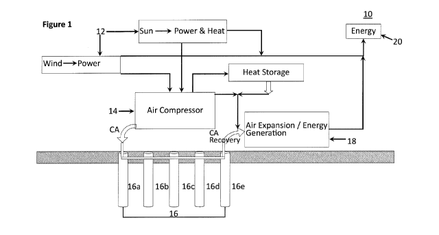
[0016] Figure 1 is a block diagram of an exemplary energy storage
system, according to an embodiment of the present application;
[0017] Figure 2 is a cross sectional view of a storage vessel,
according
to an embodiment of the present application.
[0018] Figure 3 is a block diagram of an exemplary energy storage
system, according to another embodiment of the present application;
CA 03094408 2020-09-18
WO 2019/178679
PCT/CA2019/050331
- 5 -
[0019] Figure 4 is a block diagram of an exemplary energy storage
system, according to another embodiment of the present application;
[0020] Similar reference numerals may have been used in different
figures to denote similar components.
DESCRIPTION OF EXAMPLE EMBODIMENTS
[0021] Off-peak energy, excess energy, or irregular energy from
renewable energy sources such as wind, solar, and tidal sources can be
stored as compressed air (CA) until a need for additional energy is
encountered. For example, on a warm sunny day in Ontario, solar and wind
farms generate excess electrical energy, that is given away or sold well
below cost because it cannot be consumed nor stored in Ontario.
[0022] Compressed air storage at smaller scales can help communities
and industrial entities incorporate more renewable energy and save money
at the same time. For example, if a remote mine installed a compressed air
storage system to store excess energy in the form of compressed air during
daylight hours when the wind blows, it would subsequently generate
electrical energy by the compressed air for operations at other times. If an
industrial complex or community is linked to the grid, energy stored in the
compressed air could be converted to electrical energy and returned to the
grid during peak periods to reduce energy costs of the industrial complex or
community.
[0023] An example of energy storage potential is a large industrial
complex. The complex may build a compressed air storage facility, install
wind turbines that can provide energy at 3-4 C/kWh, and recharge the
compressed air storage system with excess wind energy or with cheap, off-
peak electrical energy in the middle of the night. During the day shifts, the
compressed air system provides electrical energy to the industrial complex
when to cost of grid supplied electrical energy is higher.
CA 03094408 2020-09-18
WO 2019/178679
PCT/CA2019/050331
- 6 -
[0024] 1-50 MWh compressed air storage systems may permit
communities to be off-grid with their own renewable energy and energy
storage capacity, without having all their energy and environmental
decisions supplied by external agencies/utilities. A CWCAS system with wind
and/or solar energy inputs could provide some or even most of the
community's needs for electrical energy, allowing far greater autonomy in
planning and decarbonizing energy systems by reducing fossil fuel needs.
[0025] Figure 1 illustrates an exemplary CWCAS system 10 for storing
energy in the compressed air, according to an embodiment of the present
disclosure. The system 10 may include an energy source 12, at least one air
compressor 14 for producing compressed air using the energy from the
energy source 12, at least one storage vessel 16 for storing the compressed
air, and at least one air expander 18 for generating energy from the
compressed air released from the storage vessel 16. Surface facilities on the
ground may be used to house the air compressor 14 and the air expander
18, and/or other associated components of such equipment and the storage
vessel 16; including piping and valves used on the above surface portion of
the storage vessel 16.
[0026] In the example of Figure 1, the energy source 12 may be wind
energy generated from a wind farm or solar energy generated from a solar
farm. The energy source 12 may also be other traditional or renewable
energy source, such as natural gas generators, hydro energy, tidal energy,
or geothermal energy. The energy source 12 may directly supply energy to
consumers for use. For example, the energy source 12 may generate
electricity and directly supply it to a utility grid for nearby industrial or
residential consumers for use. The energy generated by the energy source
12 may also be converted to other forms for storage, such as compressed
gas, including air. Air is used as the examples in this disclosure, but other
gases, such as flue gas or CO2, may also be used.
[0027] In the present application, the air compressor 14 may generate
compressed air using the energy supplied from the energy source 12. In
CA 03094408 2020-09-18
WO 2019/178679
PCT/CA2019/050331
- 7 -
some examples, when the electricity generated by the energy source 12 is
more than the needs of consumers, or when consumers do not need the
electricity generated by the energy source 12 at certain period of time, such
as at the middle of the night, the extra electricity generated by the energy
source 12 may be used to power the air compressor 14 for generating
compressed air. In this case, the electricity generated by the energy source
12 may be converted to the energy stored in compressed air.
[0028] The air compressor 14 needs to have specifications to achieve
the desired energy storage capacity of the CWCAS system for a given
application. In an embodiment, the air compressor 14 may require an energy
supply of 173 to 216 kW, have an operating pressure range of 1750 to 7250
PSI (12 to 50 MPa), and a flow rate of 341 to 344 Standard Cubic Feet per
Minute (SCFM).
[0029] As illustrated in the examples of Figures 3 and 4, the air
compressor 14 may include a compressor 14a. In some examples, the air
flow input into the air compressor 14a may have a flow rate of 0.151 kg/s, a
volume flow rate of 0.149 m3/s, a pressure of 0.1 MPa and a temperature of
30 C. The compressed air flow output from the air compressor 14a has a
flow rate of 0.151 kg/s, a volume flow rate of 0.003 m3/s, a pressure of 50
MPa and a temperature of 250 C. Therefore, the air compressor 14 increases
the pressure and the temperature of the air during the compression process,
and heat is generated during the air compression process. As such, the
energy, such as electricity, from the energy source 12 is substantially
converted to heat and the mechanical energy stored in the compressed air.
[0030] In some examples, the compressed air flow output from the air
compressor 14a may be directly injected into and stored in the storage
vessel 16 without cooling the air.
[0031] If the compressed air has a high temperature, the temperature
of the air stored in the storage vessel 16 is reduced in given storage volume
at a given pressure. As well, a high temperature may accelerate the
corrosion speed of the casing materials of the storage vessel 16. In some
CA 03094408 2020-09-18
WO 2019/178679
PCT/CA2019/050331
- 8 -
examples, as shown in Figures 3 and 4, the air compressor 14 may further
include an intercooler 14b for reducing the temperature of the compressed
air to a desired temperature by capturing the heat generated from the air
compression process. The intercooler 14b may be a mechanical device used
to cool the compressed air, such as a heat exchanger that removes some of
the heat from the compressed air. The compressed air flow output from the
compressor 14a may flow into the intercooler 14b and flow out from the
intercooler with a flow rate of 0.151 kg/s, a volume flow rate of 0.003 m3/s,
a pressure of 50 MPa (or 7250 PSI) and a temperature of 200 C. As such,
the intercooler 14b decreases the temperature of the compressed air and
removes some of the heat from the compressed air. The heat captured by
the intercooler 14b may be used as heat for other processes, such as to heat
the compressed air discharged from the storage vessel 16 in the air
expansion stage to be described below, via a heat management system 15 in
Figure 4. The heat management system 15 may include a heat sink for heat
storage. In some examples, the heat captured by the intercooler 14b may be
used to heat buildings or for other beneficial uses. The heat management
system 15 may be housed in the surface facilities described above.
[0032] The compressed air output from the air compressor 14 may be
input to one or more storage vessels 16 for storage. The air compressor 14
is in a sealed, fluid communication with one or more of the storage vessels
16. For example, the compressed air may flow from the air compressor 14 to
one or more of the storage vessels 16 in one or more air-tight pipes, such as
metal pipes. The storage vessel 16 may include an array of storage vessels.
[0033] Figure 2 illustrates an exemplary storage vessel 16 which may
be a wellbore 162 cased with material that can sustain high pressure and
high temperature. For example, the wellbore 162 may be cased with a
casing 166 made from high grade steel; such casing in a wellbore is
cemented 168 in place to the surrounding rock formations. In a preferred
embodiment, such wellbore casing 166 is a high grade steel rated to high
pressure (up to 100MPa) and high temperature (up to 200 C).
CA 03094408 2020-09-18
WO 2019/178679
PCT/CA2019/050331
- 9 -
[0034] In the example of Figure 2, the storage vessel or the well 16
includes a wellbore 162 encased by a casing 166 made from material that
can sustain high pressure and high temperature and cement 168 as
described previously. In the example of Figure 2, the wellbore 162 may be a
.. vertical wellbore formed by drilling into subsurface formations 163. The
storage vessel 16 may be a high pressure-high temperature (HP-HT) well by
drilling the wellbore 162 to a depth, such as at least 500 meters and casing
the well with HP-HT rated casing 166 and cement 168. In some examples,
the well 16 may have a depth of up to 1500 meters. The depth of a well can
vary depending on the volumetric capacity of the well required for energy
storage specifications in a given application. In an embodiment the well 16
has a depth of at least 500m to 1500m. In some examples, multitude
sections of casing 164, 166 may have progressively smaller diameter casing
as the wellbore length is extended.
[0035] The wellbore 162 may be drilled in substantially any type of
rock or sediment. Oilfield rotary drilling technology may be used to drill a
HP-HT wellbore in sedimentary rock. Air hammer drilling may be used to
drill a HP-HT wellbore, providing for more rapid drilling in dense, low
permeability rocks such as granites or very dense sediments.
[0036] Cement168 is designed for the temperature and pressure range
of the CWCAS operation, for example based on mathematical modeling of
casing 166 and the stiffness of the rock mass. The casing 166 and the
cement 168 are corrosion resistant.
[0037] Due to the depth of the well 16 in the subsurface formations
163, the compressed air stored within the well 16 may be able to maintain
the temperature around 200 C at a well depth of up to 1500 meters.
[0038] An air-tight basal plug 170 may be installed at the bottom end
of the casing 166 and an air-tight top seal or valve 172 may be installed at
the top portion of the casing 166, for example at 20-50 meters beneath the
ground surface. The casing 166, the basal plug 170, and the top seal 172
define an air-tight volume or space for storing the compressed air within the
CA 03094408 2020-09-18
WO 2019/178679
PCT/CA2019/050331
- 10 -
well. In some examples, the basal plug 170 may be omitted and the casing
166 is otherwise sealed at the bottom end. The top seal 172 is configured to
accommodate tubing 174 through which the compressed air may be injected
into or discharged from the storage vessel 16. In an example, the tubing 174
may have a diameter of 15 cm or less.
[0039] A high pressure wellhead 176 caps the casing 166 and the
tubing 174. The wellhead 176 is designed to allow the injection of the
compressed air into the well 16 and discharge the compressed air from the
well 16. The tubing 174 is air-tightly connected to the wellhead 176. The
wellhead 176 may be a manifold having one or more valves or air flow
regulators that allows the storage vessel 16 to be properly managed. In
some examples, the manifold may, for example, by turning on or off the
valves, selectively allow the compressed air from the air compressor 14 to
inject into the well 16 through the tubing 174 for storage. In some
examples, the manifold 176 may, for example by turning on or off the
valves, selectively allow the stored compressed air to be discharge from the
storage vessel, through the tubing 174, from the well 16 to the air expander
18.
[0040] Because of the in situ confinement, the casing 166 may take
pressures up to 100 MPa with negligible safety risk because the entire
storage vessel 16 is under the ground, and since the top seal and the safety
valves are located below the ground surface, for example at about 25 meter
depth. If any rupture took place, pressure would simply dissipate the air
into the surrounding rock mass with no environmental impact.
[0041] In some examples, the storage vessel 16 may have a life cycle
of 20-30 years.
[0042] In some examples, the internal diameter of the casing 166 is
about 30 cm. The diameter of the casing of the well can vary depending on
the volumetric capacity of the well 16 required for energy storage
specification in a given application. In an embodiment, the volumetric
capacity of the well 16 is 7m3 per 100 meter length of the well 16 with a
CA 03094408 2020-09-18
WO 2019/178679
PCT/CA2019/050331
- 11 -
total depth of 1000m, with an air pressure of 50 MPa and a temperature of
200 C. In this example, each storage vessel or well 16 may store
compressed air that may store up to 10 MWh of energy for electricity
generation. In one example, the energy stored in the compressed air with a
conservative pressure of 25-50 MPa stored at 200 C in a single storage
vessel or well 16, which casing 166 has a diameter of 30cm and a depth of
about 1000 meters, may be in the order of 5-10 MWh of energy.
[0043] The amount of energy stored in the compressed air in one
storage vessel 16 depends on the volume of the well 16, and pressure range
of the compressed air stored therein. The temperature of air is also critical
in
energy production. The temperature range of storage is from 50-250 C. The
total volume of the well 16 may typically be 20-100 m3, the depth of the well
16 may be up to 2000 meters, the pressure of the compressed air stored in
the well 16may be 5 MPa to 100 MPa, and the temperature of the
compressed air stored the well 16 may be 50 C to 250 C. Although in these
examples, the storage vessel 16 is assumed to be vertical in orientation, the
actual well profile may be inclined or horizontal as required by a particular
application. The volume and depth of the well 16 can vary accordingly.
[0044] In an embodiment of the CWACS system, the pressure of the
storage vessel 16, the charge time, and the energy stored in the storage
vessel 16 of an air compressor 14 are shown in the table below:
Initial Pressure Final Pressure of Charge Time Total Energy
of the Vessel the Vessel (PSI) (hours) Stored in the
(PSI) Vessel(kWh)
0 7250 47 10000
3000 7250 28 6100
4350 7250 19 4100
The total energy store in the storage vessel 16 refers to the energy of the
compressed air injected into the storage vessel 16 from the initial pressure
CA 03094408 2020-09-18
WO 2019/178679
PCT/CA2019/050331
- 12 -
to the final pressure of the storage vessel 16. The charge time of a given
well can is also dependent on how many and the specifications of the
compressors equipment being used in the CWCAS system.
[0045] In some examples, the air compressor 14 may include two or
more units of the air compressors to compress the air at the same time. As
such, the charge time of the vessel 16 to a desired pressure may be
reduced. For example, if two compressor units compress the air
simultaneously, the charge time may be reduced substantially by half. As
well, the charge time may be reduced if the air compressor 14 has a larger
processing capacity, such as a faster flow rate.
[0046] In some examples, when one storage vessel 16 is insufficient
to
store the energy generated by the energy source 12, the system 10 may
expand the energy storage capacity by adding more wells or storage vessels
16. As illustrated in the example of Figure 1, the storage vessel 16 may
include an array of wells 16a, 16b, 16c, 16d, and 16e for storing the
compressed air. In this case, any series of the adjacent wells 16a, 16b, 16c,
16d, and 16e are in hydraulic communication with each other, for example,
by a manifold 17. Due to the fluidity of the compressed air in the wells 16a,
16b, 16c, 16d, and 16e, the air pressure in these wells can be substantially
the same. One or more wells 16a, 16b, 16c, 16d, and 16e may have a
tubing 174 to allow the compressed air to be injected into or to discharged
from the array of the storage vessels 16. Where the system 10 includes an
array of wells as a storage vessel 16, the compressed air may be injected
into or discharged from at least one or any combination of the wells 16a,
16b, 16c, 16d, and 16e. The system10 allows for concurrent charging and
discharging of compressed air with a storage vessel 16 comprising an array
of wells 16a, 16b, 16c, 16d, and 16e. In this example the number of wells in
the array is five wells, for illustrative purpose. The actual number of wells
can be higher or lower depending on a design of a given energy storage
project.
CA 03094408 2020-09-18
WO 2019/178679
PCT/CA2019/050331
- 13 -
[0047] As an array of storage vessels has a larger capacity to store
the
compressed air, the total energy stored increases, and as a result, the
compressed air is more likely dispatchable based on the energy demands of
the end user 20. As such, the array of storage vessels has advantages of
optimized use in terms of energy dispatchability, energy output and cost
savings. For example, if cheap excess wind energy is available, compression
and energy generation may occur at the same time, converting irregular
energy of lower value into smooth energy of higher value. Furthermore, the
heat generated during the compression process may be directly used to heat
the discharged compressed air in the air expansion process to be described
below, and the system 10 may dispatch the compressed air in the array of
storage vessels to generate electricity in a smooth manner based on the
demands.
[0048] When energy stored in the compressed air in the storage vessel
16 needs to be converted to other forms, such as electricity, the compressed
air may be discharged from the storage vessel 16. In an embodiment, the
compressed air discharged from the storage vessel 16 and flowed into the air
expander 18 has a flow rate of 0.302 kg/s, a volume flow rate of 0.005 m3/s,
a pressure of 50 MPa (or 7250 PSI) and a temperature of 200 C. If the flow
rate of the compressed air injected into the storage vessel 16 is 0.151 kg/s,
the charge time to discharge time ratio is 2:1. The actual charge-time to
discharge-time ratio may be adjusted based on project requirements and the
types of the compressor 14 and expander 18 selected.
[0049] The air expander 18 is in fluid communication with the storage
vessel 16. In some examples, the energy stored in the compressed air may
be used to generate electricity, by the air expander 18. The air expander 18
may be selected based on the energy delivery requirements, heating
conditions of the system 10 to be discussed below. The air expander 18 may
include multiple stages of expansion and reheating; and the expander
system 18 incorporates a turbine 18a and 18b for the generation of
electricity. In the expander system 18, as the high-pressure gas flows from
the high-pressure stream into the expander, the gas spins a turbine, which is
CA 03094408 2020-09-18
WO 2019/178679
PCT/CA2019/050331
- 14 -
coupled to a generator that produces electricity. This turbine is typically
connected with a crank shaft to a generator. However the expander-turbine
system 18 is typically an integrated equipment system. The expander
system 18 is chosen to handle the high pressures needed for the CWCAS
method. The air expander 18 needs to have specifications to achieve the
desired energy output capacity of the CWCAS system for a given application.
[0050] In the examples illustrated in Figures 3 and 4, the air
expander
18 may include a High Pressure (HP) turbine 18a and a Low Pressure (LP)
turbine 18b coupled to the HP turbine 18a. The high pressure compressed air
discharged from the storage vessel 16 expands in the HP turbine 18a and, as
a result of the air expansion, rotates the HP turbine 18a. The expanded air
from the HP turbine 18a then further expands and drives rotation of the LP
turbine 18b. The rotation of the HP and LP turbines 18a and 18b generates
electricity. The air expander 18 may have other configurations, for example
including more turbines, such as one or more intermediate pressure
turbines, between the HP and LP turbines. The expansion of air (from high
pressure to low pressure) in the turbines consumes heat. To avoid freezing
the turbines, the air in the turbines needs to be reheated. As well, reheating
the air in the turbine to increase the temperature of the air also increases
the expansion effects of the air in the turbines, and thus increases the
efficiency of the electricity generation. In some examples, by reheating the
compressed air in the turbines, the round-trip efficiency may be increased,
for example by 25%.
[0051] In some examples, the air expander 18 may operate at a
constant flow rate of the compressed air discharged from the storage vessel
16.-In some examples, for industrial use, the system 10 may store the
compressed air in the storage vessel at a lower pressure, such as 10 - 25
MPa, and the expander 18 may be selected to operate in the selected
pressure range.
[0052] In some examples, the system 10 may be a diabatic or an
adiabatic system. In a diabatic system, the heat generated in the air
CA 03094408 2020-09-18
WO 2019/178679
PCT/CA2019/050331
- 15 -
compressor 14 during the compression process is not used in the air
expansion process, but may be used beneficially for other purposes..
[0053] In a diabatic system configuration, the system 10 may include
a
combustor 18c to heat the air used in the HP and LP turbines 18a and 18b.
As illustrated in the example of Figure 3, when the system 10 is a diabatic
system, the stored energy in the compressed air may be released from the
storage vessel 16. The compressed air is heated by the combustor 18c
through combustion, for example by natural gas or fuel. The heated air may
be expanded in HP and/or LP turbines 18a and 18b to generate electricity, as
previously described.
[0054] In an embodiment, the temperature of the air decreases as the
air expanded in the turbines 18a and 18b. In some examples, the air
discharged from the HP turbine 18a may have a flow rate of 0.302 kg/s, a
volume flow rate of 0.005 m3/s, a pressure of 15 MPa and a temperature of
100 C. In this case, the air expander 18 may generate electricity up to 5.5
MWh if the fuel flow rate supply to the combustor 18c to reheat the air in the
turbines 18a and 18b is 0.03 kg/s. Therefore, the round trip efficiency of air
expander 18 in the diabatic system illustrated in Figure 3 is about 55%,
which is the ratio of the energy generated from the air expander 18 over the
energy stored in the storage vessel 16, for example 10 MWh.
[0055] If the diabatic system has a 55% round-trip efficiency, the
table
below shows exemplary parameters of the diabatic system illustrated in
Figure 3 in different pressurization scenarios:
Initial Pressure Final Pressure of Discharge Time Total Produced
of the Vessel the Vessel (PSI) (hours) Energy (kWh)
(PSI)
7250 14 24 5500
7250 3000 14 3400
7250 4350 9.5 2300
CA 03094408 2020-09-18
WO 2019/178679
PCT/CA2019/050331
- 16 -
[0056] Electricity of 1 MWh may support the electricity needs of
about
300 Canadian homes for one hour. The total energy produced by the
expander 18 may vary based on the type of the expander 18 or turbines and
the pressure drop after the air passes each turbine. In some examples, if
the diabatic system includes an array of 4 storage vessels 16, the system
may store compressed air capable to generate energy up to 22 MWh (5.5
MWh x 4).
[0057] As illustrated in the example of Figure 4, when the system 10
is
an adiabatic system, the heat generated during the air compression process
at the air compressor 14 may be stored in a thermal storage medium, such
as a heat sink, of the heat management system 15. In the process of air
expansion, the heat stored in the heat storage medium may be retrieved for
heating the air used in the turbines in the air expander 18. External heat
may also be supplied by external heating sources, such as a combustor 18c,
to heat the air used in the turbines in the air expander 18, so that the air
may be heated to higher temperature for generating more energy. In some
examples, when the air compression and the air expansion are conducted at
the same time, the heat generated by the air compression process by the air
compressor 14 may be directly supplied to the air used in the turbines in the
air expander 18.
[0058] In some examples, with the heat management system 15,
some of the heat generated from the compression process may be stored in
the well 16 as part of the well charging process. Some of the generated heat
may also be put to other beneficial use, for example, in space heating. Some
heat may be used to heat the air during the air expansion process at the air
expander 18. Heat management provides higher round-trip efficiencies. It
is also possible to recover waste heat from another source process, and use
this heat to warm the air during the CWCAS air expansion process to avoid
freezing of the turbines and to increase the energy output. With heat
management, round-trip efficiencies of the CWCAS system 10 may be on the
order of 70%.
CA 03094408 2020-09-18
WO 2019/178679
PCT/CA2019/050331
- 17 -
[0059] In an embodiment, the air discharged from the HP turbine 18a
may have a flow rate of 0.302 kg/s, a volume flow rate of 0.005 m3/s, a
pressure of 15 MPa and a temperature of 100 C. In this case, the air
expander 18 may generate electricity up to 7 MWh if the fuel flow rate
supply to the combustor 18c to reheat the air in the turbines 18a and 18b is
0.03 kg/s and if the heat is also supplied from the heat management system
15. Therefore, if all the required heat in the expander 18 comes from the
heat of compression 14, the system 10 is fully adiabatic and the round-trip
efficiency of air expander 18 in the adiabatic system illustrated in Figure 4
is
about 70%; which is the ratio of the energy generated from the air expander
18 over the energy stored in the storage vessel 16, for example, 10 MWh.
[0060] If the adiabatic system has about 70% round-trip efficiency,
the
table below shows exemplary parameters of the adiabatic system illustrated
in Figure 4 in different pressurization scenarios:
Initial Pressure Final Pressure of Discharge Time Total Produced
of the Vessel the Vessel (PSI) (hours) Energy (kWh)
(PSI)
7250 14 24 7000
7250 3000 14 4300
7250 4350 9.5 2900
[0061] The total energy produced by the expander 18 may vary based
on the type of the expander 18 or turbines, and the pressure drop after the
air passes each turbine. In some examples, if the adiabatic system includes
an array of 4 storage vessels 16, the system may store compressed air
capable to generate energy up to 28 MWh (7 MWh x 4).
[0062] The discharge time of a well(s) is also dependent on how many
expanders 18 are used, and the specifications of the expander equipment
used, in the CWCAS system 10. In some examples, the system 10 may
include more than one air expander 18 to increase the electricity generation
CA 03094408 2020-09-18
WO 2019/178679
PCT/CA2019/050331
- 18 -
capacity. In some examples, the compressor 14 and the air expander 18
may comprise an integral unit.
[0063] Therefore, CWCAS system 10 greatly improves renewable
energy quality, changing renewable energy from an irregularly variable and
intermittent source to a smooth, frequency-regulated and dependable
energy source.
[0064] As described above, the storage vessel 16 of system 10 has a
life cycle of 20-30 years, which is longer than the equivalent battery energy
storage life cycle of about 7 years.
[0065] As well, CWCAS system 10 has a significantly lower
environment impacts than the equivalent battery energy storage system.
Battery production uses large amounts & wide range of raw materials,
including metals and non-metals (Li, Pb, Ni, Hg, Cd, Cr etc.), which present
risks for public health and the environment. Battery industry can generate
.. considerable amounts of environmental pollutants during life-cycle,
including
hazardous waste and greenhouse gas emissions during different processes
such as mining, manufacturing, use, transportation, storage, treatment,
disposal and recycling. Energy consumption for current battery production is
estimated from 350 to 650 MJ/kW h. Studies indicate GHG emissions for
current battery production is estimated to be between 120 and 250 kg CO2-
eq/kW h. Battery use at a large scale or grid-scale (> 50 MW) will have
significant environmental impacts. There are legitimate concerns that large-
scale battery energy storage systems are not environment friendly and not
sustainable.
[0066] In contrast, CWCAS system 10 provides an advanced type of
Compressed Air Energy storage solution: system 10 provides an alternative
energy storage option for bulk energy management, and has low Cradle-to-
Grave environmental impact; system 10 may increase renewable energy
supply in electrical generation systems. The system 10 is compatible with
CA 03094408 2020-09-18
WO 2019/178679
PCT/CA2019/050331
- 19 -
geothermal, wind and solar energy generation, and compatible with grid, off-
grid systems and micro-grid applications.
[0067] The CWCAS system 10 may be conveniently deployed to meet
the energy needs of a geographic area and/or application. The system 10
may easily be customized and flexibly scaled to allow local communities to
self-regulate their energy sources, as their needs require. The configuration
of system 10 may be based on local needs. Based on the capacity of the
energy source 12 and the needs of the area/application, suitable type and
size of air compressor 14 and the air expander 18 systems may be selected.
The configuration of the storage vessel 16, including the depth of the well,
the diameter of the casing 166 may also be selected to provide the volume,
mass, temperature and pressure of the stored compressed air to be
compatible with the capacity of the of air compressor 14 and the air
expander 18. As described above, additional storage vessels 16 may be
created in the subsurface to expand the storage capacity of the compressed
air, for example, by drilling and tying-in additional storage vessels.
[0068] As well, the CWCAS system 10 is not site specific and may be
located almost anywhere in any environment. For example, system 10 may
be deployed in remote communities or for use in industrial applications. On
the other hand, other compressed air storage systems that use salt caverns,
water bladders, etc., are limited to the location of the salt caverns or water
bladders. The system 10 may also be installed at a suitable scale, and easily
expanded to provide increased energy storage capacity based on future
growing needs through the drilling of additional storage vessels 16. For
example, the system 10 has the flexibility to be located near, and tied into,
existing/legacy electricity transmission infrastructure to service larger
markets; and reduce the need/cost for building new electricity transmission
systems.
[0069] The system 10 may be used in various applications, including
industry, oilfield, and utilities. For example, the system 10 may convert
oilfield wells to energy storage vessels 16 by using the existing wells of the
CA 03094408 2020-09-18
WO 2019/178679
PCT/CA2019/050331
- 20 -
oilfields as storage vessels, with suitable modifications to seal such wells.
The flare gas (from upstream petroleum activities, for example) may be used
as an energy source 12 to drive the compressor 14, or in heating the air in
the turbines of expander 18. As well, in peak management of energy supply,
the system 10 allows the storing of excess energy in the storage vessel 16
for future beneficial use; such as by generating electricity, and provides
arbitrage opportunity with a grid provider, by selling the electricity at the
peak hour of electricity consumption.
[0070] Certain adaptations and modifications of the described
embodiments can be made. Therefore, the above discussed embodiments
are considered to be illustrative and not restrictive.