Note: Descriptions are shown in the official language in which they were submitted.
Docket No. P9907CA00
HEATED BEVERAGE CONTAINER
FIELD
[0001] The specification is directed to heated containers for beverages.
BACKGROUND
[0002] Dishware such as cups and mugs are commonly used to hold beverages.
However,
hot or warm beverages contained in conventional dishware will lose heat
overtime. Dishware
may be heated with an electric coaster, but this solution is not portable.
Additionally, ceramic
mugs are poor thermal conductors and are ill-suited to transfer heat from an
external heat
source to the beverage.
[0003] Vacuum-insulated flasks are capable of maintaining heat in a
beverage for a longer
period of time than ceramic mugs, but not indefinitely. Additionally, vacuum
flasks require a lid to
effectively keep a beverage warm and are not typically dishwasher-safe.
SUMMARY
[0004] It is an aspect of the present invention to provide an apparatus for
heating beverages.
[0005] The above aspect can be attained by an apparatus that includes a base
and a container
for holding liquids. The base has a heater plate that is heated by one or more
heater elements
attached to the heater plate. A power source in the base provides electricity
to the heater
elements. The base is removably attachable to the container. The container has
an inner cup
that sits inside a chassis. The inner cup is made of a conductive material and
has an open top
for receiving liquid, a circumferential wall, and a bottom portion. The
chassis has an open top for
receiving a liquid, a circumferential wall, and an open bottom. When the
container is attached to
the base, the bottom portion of the inner cup is configured to contact the
heater plate and
receive heat from the heater plate.
[0006] These together with other aspects and advantages which will be
subsequently apparent,
reside in the details of construction and operation as more fully hereinafter
described and
claimed, reference being had to the accompanying drawings forming a part
hereof, wherein like
numerals refer to like parts throughout.
Date Recue/Date Received 2020-10-01 1
Docket No. P9907CA00
BRIEF DESCRIPTION OF THE DRAWINGS
[0007] FIG. 1 is a perspective view of an apparatus for heating beverages.
[0008] FIG. 2 is a front view of the apparatus from FIG. 1.
[0009] FIG. 3 is a left side view of the apparatus from FIG. 1.
[0010] FIG. 4 is a right side view of the apparatus from FIG. 1.
[0011] FIG. 5 is a rear view of the apparatus from FIG. 1.
[0012] FIG. 6 is a top view of the apparatus from FIG. 1.
[0013] FIG. 7 is a bottom view of the apparatus from FIG. 1.
[0014] FIG. 8 is an exploded view of the apparatus from FIG. 1.
[0015] FIG. 9 is an exploded view of a lid.
[0016] FIG. 10 is a side view of the lid of FIG. 9.
[0017] FIG. 11 is a sectional view of the lid of FIG. 9.
[0018] FIG. 12 is an exploded view of a container.
[0019] FIG. 13 is a perspective view of an inner cup.
[0020] FIG. 14 is a side view of the inner cup of FIG. 13
[0021] FIG. 15 is a top view of the inner cup of FIG. 13
[0022] FIG. 16 is a bottom view of the inner cup of FIG. 13
[0023] FIG. 17 is a perspective view of a gasket.
[0024] FIG. 18 is a side view of the gasket of FIG. 17.
[0025] FIG. 19 is a top view of the gasket of FIG. 17.
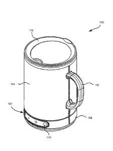
[0026] FIG. 20 is a bottom view of the gasket of FIG. 17.
[0027] FIG. 21 is a perspective view of a chassis.
[0028] FIG. 22 is a top view of the chassis of FIG. 21.
[0029] FIG. 23 is a bottom view of the chassis of FIG. 21.
[0030] FIG. 24 is a rear view of the chassis of FIG. 21.
Date Recue/Date Received 2020-10-01 2
Docket No. P9907CA00
[0031] FIG. 24 is a sectional view of the chassis of FIG. 21.
[0032] FIG. 26 is a partial sectional view of the chassis of FIG. 21.
[0033] FIG. 27 is a partial sectional view of the chassis of FIG. 21.
[0034] FIG. 28 is a perspective view of a base.
[0035] FIG. 29 is a top view of the base of FIG. 28.
[0036] FIG. 30 is a bottom view of the base of FIG. 28.
[0037] FIG. 31 is a front view of the base of FIG. 28.
[0038] FIG. 32 is a rear view of the base of FIG. 28.
[0039] FIG. 33 is a left side view of the base of FIG. 28.
[0040] FIG. 34 is a right side view of the base of FIG. 28.
[0041] FIG. 35 is an exploded view of the base of FIG. 28.
[0042] FIG. 36 is a perspective view of a heater plate.
[0043] FIG. 37 is a side view of the heater plate of FIG. 36.
[0044] FIG. 38 is a sectional view of the heater plate of FIG. 36.
[0045] FIG. 39 is a perspective view of a flex ring.
[0046] FIG. 40 is a top view of the flex ring of FIG. 39.
[0047] FIG. 41 is a bottom view of the flex ring of FIG. 39.
[0048] FIG. 42 is a side view of the flex ring of FIG. 39.
[0049] FIG. 43 is a perspective view of an insulating plate.
[0050] FIG. 44 is a top view of the insulating plate of FIG. 43.
[0051] FIG. 45 is a perspective view of a microcontroller.
[0052] FIG. 46 is a top view of the microcontroller of FIG. 45.
[0053] FIG. 47 is a left side view of the microcontroller of FIG. 45.
[0054] FIG. 48 is a right side view of the microcontroller of FIG. 45.
[0055] FIG. 49 is a bottom view of the microcontroller of FIG. 45.
Date Recue/Date Received 2020-10-01 3
Docket No. P9907CA00
[0056] FIG. 50 is a top view of the heater element of FIG. 50.
[0057] FIG. 51 is a schematic view of a heating system.
[0058] FIG. 52 is a graph showing temperature curves.
[0059] FIG. 53 a flowchart of a method of regulating temperature.
[0060] FIG. 54 is a perspective view of a warming apparatus.
[0061] FIG, 55 is an exploded view of the warming apparatus of FIG. 54.
[0062] FIG. 56 is a cut-away of the warming apparatus of FIG. 54.
[0063] FIG. 57 is an exploded view of the warming apparatus of FIG. 54.
[0064] FIG. 58 is a perspective view of another warming apparatus.
[0065] FIG. 59 is an exploded view of the another warming apparatus of FIG.
58.
DETAILED DESCRIPTION
[0066] An apparatus for heating beverages is disclosed. The apparatus includes
a container for
holding liquids and a base for heating the container. Unlike a heated coaster,
the apparatus is
portable. The base includes a rechargeable power source so the apparatus does
not need to be
plugged in during use. Additionally, the base is attachable to the container
so that the container
can easily be carried around while still heated by the base. Since the
container contains no
electronic components and is detachable from the base, the container may be
washable or even
machine-washable. Unlike a washable ceramic mug, however, the container has an
inner cup
made of a conductive material so that heat is efficiently transferred from the
base into the
beverage.
[0067] To increase the lifespan of the power source and to keep the beverage
warm for longer,
the container is double-walled, having an inner cup nested inside a chassis.
The chassis has an
open bottom, leaving the bottom of the inner cup exposed. In this
configuration, the base can
directly contact the inner cup, which allows for efficient heat transfer
between the base and the
inner cup.
[0068] The features of the apparatus will now be described by way of reference
to the drawings.
[0069] Referring to FIGs. Ito 8, an apparatus for heating beverage containers
is generally
shown at 100. The apparatus 100 includes a container 104 for holding liquids
and a base 108
Date Recue/Date Received 2020-10-01 4
Docket No. P9907CA00
for heating the liquids inside the container 104. In some embodiments, the
apparatus may have
a lid 112 for keeping liquids inside the container 104. The container 104 may
include a handle
116 for manipulating the container.
[0070] The container 104 contains no electronic components for heating
liquids. Instead, liquids
are heated by the base 108, which applies heat to the container 104. A power
port 120 may be
included in the base 108 for receiving current from a charging cord, for
example, a USB cable.
The base 108 may be operated with an input device 124. The input device 124
may include, but
is not limited to, a control panel, a remote control, a tablet, a smartphone,
a personal computer.
In the example shown in FIGs. 1-8, the input device 124 is a control panel
with a plurality of
buttons 130. Each of the buttons 130 may correspond to a desired temperature
for the liquid,
increases or decreases to the current temperature of the liquid, "on" or "off"
status, or other
functions known in the art. For example, the input device 124 may include a
"high", "medium",
and "low" button where "high" corresponds to a liquid temperature of about 70
C, "medium"
corresponds to a liquid temperature of about 65 C, and "low" corresponds to a
liquid
temperature of about 60 C. The buttons 130 may also include a power button for
turning the
base 108 "ON" and "OFF'. The function of the buttons 130 may be indicated by
colors, sizes,
shapes, textures, symbols, characters, or any combination thereof. In one
example, the buttons
130 may include a power button indicated by a symbol and three buttons
corresponding to low,
medium, and high heat as indicated by the size of the button. The buttons 130
may include
lights that are activated responsive to pressure and/or signals received by a
microcontroller
(described later).
[0071] Turning now to FIGs. 9 to 11, a lid 112 is illustrated generally at
112. The lid 112 may be
insertable into the open top of the inner cup (154 in FIG. 12). The lid 112
may be adapted to
prevent liquids from spilling out of the container (104 in FIGs. 1-11). For
example, the diameter
of the lid 112 may be approximately the same as the inner diameter of the
container 104. The lid
may further include a ring 132 for sealing the lid 112 to the container 104.
The ring 132 may
comprise rubber OF silicone or another flexible material to improve the seal
between the lid 112
and the container 104. Removal of the lid 112 may be assisted by a tab 136.
[0072] The lid may further include an aperture 138 for dispensing beverages
from the container
104. The aperture 138 may be disposed in a top surface of the lid 140 that
covers the open top
of the container (shown at 154 in FIG. 12). The top surface of the lid 140 may
be inclined so that
liquid dispensed from the aperture 138 onto the top surface of the lid 140 is
conveyed back
Date Recue/Date Received 2020-10-01 5
Docket No. P9907CA00
towards the aperture 138. A raised portion 144 may further assist in conveying
liquid towards
the aperture 138.
[0073] An exploded view of the container 104 is illustrated in greater detail
in FIG. 12. The
container has a chassis 148 and an inner cup 152 nested inside the chassis
148. The inner cup
152 is configured to hold liquid and the chassis 148 is configured to insulate
the inner cup 152.
[0074] The chassis 148 has an open bottom (shown later), an open top 150 for
receiving liquid,
and a circumferential wall 151. The inner cup 152 is nested inside the
chassis. The inner cup
152 has an open top 154 for receiving liquid, a closed bottom (shown later)
for retaining liquid,
and a circumferential wall 155 that is spaced from the circumferential wall
151 of the chassis to
define an annular gap (shown later in FIG. 25), When the inner cup 152 is
nested inside the
chassis 148, a lip 156 of the inner cup 152 may overlap with a top edge 160 of
the chassis 148.
The container 104 may further comprise a sealing mechanism for sealing the
annular gap. The
sealing mechanism may prevent water and other liquids from becoming trapped
between the
chassis 148 and the inner cup 152. The sealing mechanism may be adapted to
maintain a seal
between the chassis 148 and the inner cup 152 as the inner cup 152 heats up
and cools down.
Since the inner cup 152 receives heat from the base 108, the inner cup 152 may
expand during
use of the apparatus. When the base 108 is not in use, the inner cup 152 may
shrink in size.
This thermal expansion and contraction may cause the lip 156 to pull away from
the top edge
160 of the chassis 148. The sealing mechanism may assist in maintaining the
seal during
thermal expansion and contraction.
[0075] The sealing mechanism may include a gasket 164 and a metal ring 166.A
metal ring
166 may be attached to an outer surface 168 of the circumferential wall 155. A
bottom portion of
the chassis (shown later) may then attached to the metal ring 166 with the at
least two fasteners
172, which are accommodated by apertures 176 in the metal ring 166 and
apertures (shown
later) in the chassis 148. As the fasteners 172 are tightened, the inner cup
152 is biased
towards the bottom portion of the chassis (shown later). The gasket 164 is
fitted between the
chassis and the inner cup 152 such that, when the fasteners 172 are tightened,
the gasket 164
is squeezed between the chassis 148 and the inner cup 152. The gasket 164 may
comprise
rubber, silicone, or another flexible material, to improve the seal between
the chassis 148 and
the inner cup 152. The gasket 164 may further include apertures 180 for
accommodating the
fasteners 172.
Date Recue/Date Received 2020-10-01 6
Docket No. P9907CA00
[0076] The sealing mechanism may further include a sealant between the lip 156
and the top
edge 160.
[0077] The sealing mechanism may further include a sealant between the chassis
148 and the
metal ring 166 to assist in sealing the chassis 148 to the metal ring 166. In
some embodiments,
a sealant may be applied to the gasket 164 to assist in sealing the gasket 164
to the chassis
148 and/or the inner cup 152. The sealant may prevent water from entering the
annular gap
(shown later).
[0078] The inner cup 152 may be adapted to receive heat from the base 108 and
transfer the
heat to a liquid contained in the inner cup 152. The inner cup 152 may
comprise a conductive
material, such as metal, to quickly and efficiently absorb heat from the base
108 and release
heat into the liquid. The chassis 148 on the other hand, may comprise metal,
ceramic, polymer,
carbon composite, wood, or another suitable material. The material for the
chassis 148 may be
selected for aesthetic reasons, to minimize cost, or to inhibit heat
conduction from the inner cup
152. The chassis 148 may include a handle 116 for manipulating the container
104.
[0079] The inner cup 152 is illustrated in FIGs. 13-16. The inner cup 152 has
an open top 154
for receiving liquids and a closed bottom 188 for retaining liquids. The inner
cup 152 may be
substantially frustoconical in shape, with the closed bottom 188 having a
diameter that is
smaller than the diameter of the open top 154. The metal ring 166 may be
disposed on the outer
surface 168 proximal to the closed bottom 188. The metal ring 166 may include
at least one
aperture for accommodating at least one fastener 172. In the example shown in
FIG. 16, the
metal ring 166 includes four apertures 176. The inner cup 152 may comprise a
material that is
food-safe and conducts heat well.
[0080] Turning now to FIGs. 17-20, the gasket 164 is illustrated in greater
detail.
[0081] The gasket 164 is sized and shaped to fit between the inner cup 152 and
the chassis
148, so as to seal the inner cup 152 to the chassis 148. The gasket 164 is
configured to
accommodate the inner cup 152, with the inner surface of the gasket 196 in
contact with the
outer surface of the inner cup 168. The inner surface of the gasket 196 may
comprise a series
of radial ridges for improving the seal between the gasket 164 and the inner
cup. The outer
surface of the gasket 198 may be adapted to seal the gasket 164 to the chassis
148, with the
outer surface of the gasket 198 in contact with a bottom portion of the
chassis (described below
with respect to FIGs. 21 to 23). The outer surface of the gasket 198 may
comprise a series of
Date Recue/Date Received 2020-10-01 7
Docket No. P9907CA00
radial ridges for improving the seal between the gasket 164 and the chassis
148.
[0082] The gasket 164 may further comprise at least two protrusions 199 for
the at least two
apertures 180. In the embodiment shown in FIGs. 17-20, the gasket has four
apertures 180,
corresponding to the four apertures on the metal ring 166. The at least two
protrusions 199 may
be positioned between the bottom portion of the chassis (described later) and
the metal ring
166.
[0083] The chassis 148 is illustrated at FIGs. 21 to 23. FIG. 21 is a bottom
perspective of the
chassis 148, FIG. 22 is a top view, and FIG. 23 is a bottom view.. The chassis
148 has an open
bottom 200 for accessing the closed bottom of the inner cup 188 and the
fasteners 172. When
the inner cup 152 is inserted into the chassis 148, an inner surface of the
chassis 204 faces the
outer surface of the inner cup (shown later). A bottom portion of the chassis
208 is configured to
seal the chassis 148 to the inner cup 152. The bottom portion of the chassis
208 includes at
least two apertures 212 for accommodating fasteners. The chassis 148 may
further include an
attachment mechanism 216 for removably attaching the chassis 146 to the base
108. The
attachment mechanism 216 may include a bayonetting system, magnets, threading,
clips, lap
joints, or another suitable mechanism.
[0084] Turning to FIGs. 24 to 27, the container is illustrated at 104, showing
the inner cup 152
seated in the chassis 138.
[0085] FIG. 25 shows a cross-section of the container 104 at plane B-B.
Because the inner cup
has a roughly frustoconical shape and the chassis 148 is roughly cylindrical,
there is an annular
gap 220 between the inner surface of the chassis 204 and the outer surface of
the inner cup
168. The annular gap 220 may inhibit the dissipation of heat from the inner
cup 152. When the
container 104 is assembled, the chassis 148 may be sealed to the inner cup 152
to prevent
liquids from entering the annular gap 220. To further inhibit the dissipation
of heat from the inner
cup 152, the annular gap 220 may contain a gas or it may be vacuum-sealed.
[0086] Because the inner cup 152 comprises a conductive material and the
chassis 148 may
comprise a material that is a poor heat conductor, the inner cup 152 and the
chassis 148 may
expand and contract at different rates when exposed to heat. For example, a
user may wish to
clean the container 104 in a dishwasher, exposing the container 104 to high
temperatures. The
difference between the two rates of expansion may be greater or less,
depending on the
materials selected for the chassis 148 and the inner cup 152. Additionally,
the inner cup 152 will
Date Recue/Date Received 2020-10-01 8
Docket No. P9907CA00
be exposed to heat sources that the chassis 148 is not exposed to, such as the
heat applied by
the base 108 and heat from a hot liquid received by the inner cup 152. Because
of the annular
gap 220, heat does not transfer quickly between the inner cup 152 and the
chassis 148.
Accordingly, the sealing mechanism is configured to seal the annular gap 220
as the inner cup
152 expands and contracts.
[0087] As the inner cup 152 expands, the lip 156 may pull away or lose contact
with the top
edge of the chassis 160. To counteract the tendency of the inner cup 152 to
become unsealed
from the chassis 148, at least two fasteners 172 may tighten the sealing
mechanism. Although
not shown in this view, the fasteners 172 may pass through the bottom portion
of the chassis
208, and the metal ring 166. Tightening the fasteners will bias the metal ring
106 towards the
bottom portion of the chassis 208. This may enhance the seal between the
chassis 148 and the
inner cup 152 at both the top edge of the chassis 160 and the bottom portion
of the chassis 208.
[0088] FIG. 26 is an enlarged view of C, showing the seal between the lip 156
and the top edge
of the chassis 160. When the fasteners 172 are tightened, the lip 156 may be
biased towards
the top edge 160 of the chassis. This may enhance contact between the lip 156
and the top
edge 160.
[0089] FIG. 27 is an enlarged view of D, showing the seal between the inner
cup 152, the
gasket 164, and the bottom portion of the chassis 208. When the fasteners 172
are tightened,
the inner cup 152 is biased toward the bottom portion of the chassis 208. This
may enhance
contact between the outer surface of the inner cup 168 and the gasket 164.
This may also
improve contact between the gasket 164 and the bottom portion of the chassis
208. The gasket
164 may comprise a flexible or compressible material such as rubber, silicone,
or another
suitable material.
[0090] As shown in FIG. 27, the closed bottom 188 of the inner cup 152 is
exposed by the open
bottom 200 of the chassis. Consequently, the inner cup 152 may directly
contact the base 108.
The closed bottom 188 may be thin, to quickly conduct heat from the base 108
to the liquid
contained in the inner cup 152. The circumferential wall 155 may also be thin,
to quickly conduct
heat from the closed bottom 188. In some embodiments, the closed bottom 188
and the
circumferential wall 155 may have a thickness of about 0.3 to about 0.9
millimeters, and more
preferably about 0.5 to about 0.6 millimeters.
[0091] When the container 104 is attached to the base 108, the closed bottom
188 is pressed
Date Recue/Date Received 2020-10-01 9
Docket No. P9907CA00
into the base 108, causing the heater plate 240 to substantially contact the
base 108. To
improve contact and therefore heat transfer from the base, the closed bottom
188 may be sized
and shaped accordingly. The materials and thickness of the closed bottom 188
may be chosen
such that the closed bottom 188 is semi-flexible. In embodiments with a semi-
flexible closed
bottom 188, the closed bottom will be pressed into the base 108 when the
container 104 is
attached to the base, causing the closed bottom 188 to flex and improving
contact between the
inner cup 152 and the heater plate (shown later). In some embodiments with a
semi-flexible
closed bottom 188, the closed bottom 188 is slightly convex. For example, the
closed bottom
188 may be substantially flat with a tolerance of approximately 0.2 to 0.3
millimeters, and more
preferably about 0.25 millimeters. In these embodiments, when the container
104 is attached to
the base 108, the heater plate (shown later) exerts pressure on the closed
bottom, reducing the
convexity of the closed bottom 188. Thus, when the container 104 is attached
to the base 108,
the closed bottom 188 is pressed substantially flat.
[0092] FIGS. 28 to 34 show the base at 108. The base may have an outer shell
228, 276 for
enclosing a number of electronic components. The outer shell 228, 276 may
comprise an upper
portion 228 and a bottom portion 252. The outer shell 228, 276 may further
include an
attachment mechanism 234 for attaching to the container 104.
[0093] The base 108 is adapted to provide heat to the inner cup 152. In this
embodiment, the
base 108 includes a heater plate 240 which is configured to contact the closed
bottom of the
inner cup 188 when the container 104 is attached to the base 108. The heater
plate 240 is
configured to transmit heat to the inner cup 152. The base 108 may be operated
by an input
device 124. The input device may include a number of buttons 130 for
controlling the amount of
heat delivered by the heater plate 240. The base 108 may include a power port
120 for
receiving electrical power.
[0094] The base 108 may further include a sealing ring 248 for sealing the
heater plate 240 to
the upper portion of the outer shell 228. Since the heater plate 240 is
configured to conduct
heat, it will expand and contract during use. The sealing ring 248 may
comprise a compressible
material such as rubber or silicone to accommodate the expansion and
contraction of the heater
plate 240. The sealing ring 248 may also be compressed when the container 104
is attached to
the base. The materials and dimensions of the sealing ring 248 may be selected
to exert
pressure against the heater plate when the container 104 is attached to the
base. This may
increase the contact between the heater plate and the closed bottom of the
container 188.
Date Recue/Date Received 2020-10-01 10
Docket No. P9907CA00
[0095] As shown in FIG. 31, the heater plate 240 may be raised above the
sealing ring 248, and
the sealing ring 248 may be raised above the upper portion of the outer shell
228. In this
configuration, any liquid that is spilled on the heater plate 240 or sealing
ring 248 may (assisted
by gravity) roll off the base 108. In some configurations, the sealing ring
248 may be inclined to
further prevent liquid from pooling on the heater plate 240 and sealing ring
248.
[0096] The base 108 may include a bottom 252. The bottom may comprise a high
friction
material such as rubber or silicone for stabilizing the base 108 on a surface.
[0097] An exploded view of the base 108 is shown in FIG. 35. The base
includes at least
one heater element 256 for applying heat to the heater plate 240. The heater
element 256 may
comprise a material with high heat resistance, for example a polyimide. The
heater element 256
may be adhered to the heater plate 240. On the side of the heater element 256
opposite the
heater plate 240, there may be an insulating plate 260. The insulating plate
260 may be
configured to conserve energy by reflecting heat from the heater element 256.
The insulating
plate 260 may be further configured to protect the electronic components from
the heat
generated by the heater element 256.
[0098] The base 108 further includes a microcontroller 264 for controlling
the heater
element 256. The microcontroller 264 may be powered by a power source 268, for
example a
battery.
[0099] The microcontroller 264 may be configured to receive inputs from the
input device
124. In this example, a flexible printed circuit board 272 is attached to the
input device 124 with
a pressure sensitive adhesive. When pressure is applied to the input device
124, an input signal
is sent to the microcontroller 264. Power may be provided to the input device
124 by the power
source 268.
[00100] The base may be enclosed by a bottom portion 276 of the shell. The
base 108 may
be held together with fasteners. A first set of fasteners 280 may attach the
microcontroller 264 to
the insulating plate 260. A second set of fasteners 284 may attach the bottom
portion of the
shell to the upper portion of the shell 228. The high friction bottom 252 may
be adhered to the
bottom portion 276.
[00101] The heater plate 240 is shown in FIGs, 36 to 38. The heater plate 240
has a center
portion 288 and an edge portion 292 that may be at least partially covered by
the sealing ring
248. The center portion 288 may be raised so that when the edge portion 292
that covered by
Date Recue/Date Received 2020-10-01 11
Docket No. P9907CA00
the sealing ring, an outer surface of the heater plate 294 is raised above a
top surface of the
sealing ring. The outer surface 294 is substantially planar. When the
container 104 is attached
to the base 108, the top surface 294 is substantially in contact with the
closed bottom of the
inner cup.
[00102] FIG. 38 shows a cross-section of the heater plate 240 at plane E-E.
The center
portion 288 has an inner surface 296 on a side opposite the outer surface 294.
The inner
surface 296 is in direct contact with the heater element 256 so as to receive
heat from the
heater element 256. In order to transfer heat quickly and efficiently from the
heater element 256
to the container 104, the heater plate 240 may comprise a metal with high heat
conductivity.
Heat transfer may be improved in embodiments with a relatively thin center
portion 288. In some
embodiments, the center portion 288 may have a thickness of about 0.3 to about
0.9
millimeters, and more preferably about 0.5 to about 0.6 millimeters.
[00103] When the container 104 is attached to the base 108, the inner cup 152
is pressed
into the heater plate 240, causing the heater plate 240 to substantially
contact the inner cup
152. To improve contact and therefore heat transfer to the inner cup 152, the
heater plate 240
may be sized and shaped accordingly. The materials and thickness of the heater
plate 240 may
be chosen such that the heater plate 240 is semi-flexible. In embodiments with
a semi-flexible
heater plate 240, the inner cup 152 is pressed into the heater plate 240 when
the container 104
is attached to the base 108, causing the heater plate 240 to flex and
improving contact between
the heater plate 240 and the inner cup 152. In some embodiments with a semi-
flexible heater
plate 240, the heater plate 240 is slightly convex. For example, the heater
plate 240 may be
substantially flat with a tolerance of approximately 0.2 to 0.3 millimeters,
and more preferably
about 0.25 millimeters. In these embodiments, when the container 104 is
attached to the base
108, the inner cup 152 exerts pressure on the closed bottom, reducing the
convexity of the
heater plate 240. Thus, when the container 104 is attached to the base 108,
the heater plate
240 is pressed substantially flat.
[00104] The heater element 256 may be powered by the power source 268. The
power
source 268 may be selected to power the heater element 246 for a suitable
period of time
between charges. Increasing the efficiency of heat exchange between the heater
plate 240 and
the inner cup 152, as described above, can increase the period of time between
charges.
Date Recue/Date Received 2020-10-01 12
Docket No. P9907CA00
[00105] The sealing ring 248 is shown in FIGs. 39 to 42. The sealing ring
248 may have a
plurality of teeth 298 on a lower surface 306 for attaching to the shell 228.
An upper surface 302
of the sealing ring may be substantially fiat.
[00106] Turning now to FIGs. 43 and 44, the insulating plate is shown
generally at 260. The
material and thickness of the insulating plate 260 may be selected to reflect
heat emitted from
the heater element 256 towards the heater plate 240.
[00107] The insulating plate 260 may include a first set of apertures 308
for accommodating
the fasteners 280 that attach the microcontroller 264 to the insulating plate
260. A second set of
apertures 312 may be included for accommodating the fasteners 264 that attach
the bottom
portion of the shell 276 to the upper portion of the shell 228. One or more
apertures 316 may be
included to accommodate wires (not shown). For example, wires attaching the
heater element
to the microcontroller 264.
[00108] FIGs. 45 to 49 show the microcontroller 264. The microcontroller
264 may comprise
a circuit board 320 including a number of components for controlling the
heater element. The
microcontroller 264 includes a board 320 for supporting the components of the
microcontroller
264. The board 320 may include a plurality of apertures 324 for accommodating
fasteners to
attach the microcontroller 264 to the insulating plate 260. The
microcontroller 264 may further
include a heater connector 340 for electrically connecting the microcontroller
264 to the heater
element (shown in FIG. 35). The microcontroller 264 may include a power port
120 for receiving
a charging cable (not shown). In this example, the power port 120 is a USB-C
type connector.
The power port 120 is configured to receive current from a charging cable (not
shown) and
transfer current to a power source connector 348. The power source connector
348 is
configured to transfer current to the power source 268. The microcontroller
264 may also
include an input device connector 356. The input device connector 356 is
configured to receive
an input signal from the input device.
[00109] Referring now to FIG. 50, the heater element is shown generally at
256. The heater
element may substantially comprise a disc 360. In the embodiment shown, the
disc is circular in
shape, but the shape of the disc is not particularly limited. The size and
shape of the disc 360
may be chosen to substantially align with the size and shape of the heater
plate 240. The heater
element 256 may include an aperture 364 for accommodating a temperature sensor
(described
below with respect to FIG. 51).
Date Recue/Date Received 2020-10-01 13
Docket No. P9907CA00
[00110] FIG. 51 is a schematic diagram 368 showing how the temperature sensor
372 and
heater element 376 are electrically connected. The temperature sensor 372 may
receive current
from the power source from a first pin 380. The temperature sensor detects the
temperature of
the heater element 376 and generates a temperature signal indicative of the
heater element's
temperature. The temperature signal is sent to the microcontroller 264 via a
second pin 384. A
third pin 388 for grounding is also connected to the temperature sensor. A
wire 390 connects the
temperature sensor to the heater element 376 which generates heat. The heater
376 is
configured to transfer the heat into the heater element 376. Current from the
heater element 376
is returned to the power source 268 via a fourth pin 392.
[00111] The microcontroller 264 may include a computer-readable storage medium
that is
programmed with an algorithm. The microcontroller 264 can execute instructions
stored on the
computer-readable storage medium, which when executed, cause the
microcontroller 264 to
perform the algorithm. The microcontroller 264 may be configured to determine,
based on the
temperature signal and the input signal, whether to increase or decrease power
to the heater
element 376. The microcontroller 264 may be programmed to determine the
temperature rate of
change based on the temperature signal received at two different time points.
The
microcontroller 264 can then compare the temperature rate of change with a
plurality of
temperature curves.
[00112] FIG. 52 is a graph showing examples of temperature curves under three
possible
scenarios: (1) a temperature curve expected for the temperature sensor if no
container 104 is
attached to the base 108; (2) a temperature curve expected for the temperature
sensor if an
empty container 104 is attached to the base 108; and (3) a temperature curve
expected for the
temperature sensor if a container 104 holding hot liquid (70 C) is attached to
the base 108.
[00113] In FIG. 52, the temperature rate of change for the heater plate 240
when the
container 104 is empty is indicated by the dashed line. If the temperature
rate of change is
approximately that expected for an empty container, then the microcontroller
264 may determine
that the container 104 is attached to the base but the container 104 is empty.
If the temperature
rate of change is below that expected for an empty container, the
microcontroller 264 may
determine that the mug contains a warm or cold liquid. The increased thermal
mass would
lessen the rate of temperature increase, as compared with an empty container.
[00114] The temperature rate of change for the heater plate 240 after a hot
liquid has been
poured into the container 104 is indicated by the dotted line. lithe
temperature rate of change is
Date Recue/Date Received 2020-10-01 14
Docket No. P9907CA00
at or above that expected when a hot liquid is poured into the container 104,
then the
microcontroller 264 may determine that the container 104 holds a hot liquid.
When a hot or
warm liquid is added to the container 104, heat from the liquid may transfer
into the inner cup
and subsequently into the heater plate 240. The heater plate 240 may reach a
temperature
close to that of the liquid.
[00115] The temperature rate of change for the heater plate 240 when the
container 104 is
not attached to the base is indicated by the dashed and dotted line. If the
temperature rate of
change is similar to that expected if the container 104 is not attached to the
base, the
microcontroller may determine that the container 104 is not attached to the
base and turn the
heater element is "OFF". When the container 104 is not attached to the base
108 and the heater
element 376 is "ON", the heater plate 240 may increase temperature rapidly.
The microcontroller
264 may turn "OFF" the heater element 376 to avoid wasting power and to avoid
the danger of
an exposed hot surface.
[00116] The computer-readable storage medium may store a plurality of
temperature curves
representing various volumes, temperatures, and compositions of liquids that
may be contained
in the apparatus.
[00117] The microcontroller 264 may also control the heater element 376 based
on an input
signal. The input signal may be generated at the input device 124. The
algorithm may determine
a threshold temperature based on the input signal. The threshold may be a
temperature or
ranges of temperatures. If the algorithm determines that the temperature of a
liquid in the
container is above the threshold temperature indicated by the input signal,
the microcontroller
264 may control the heater element 376 to turn "OFF". Conversely, if the
algorithm determines
that the temperature of a liquid in the container is below the threshold
temperature indicated by
the input signal, the microcontroller 264 may control the heater element 376
to turn "ON".
[00118] FIG. 53 is a flowchart showing a method of controlling the
temperature in a liquid at
430. This method 400 is a proportional, integral (PI) control loop, but the
microcontroller may be
programmed to implement a number of suitable methods. The method 400 starts at
432 with the
microcontroller 264 determining the temperature rate of change of the heater
element 376
based on at least one temperature signal sent by the temperature sensor. At
436, the
microcontroller determines whether or not the temperature has increased. If
the temperature
has not increased, the microcontroller 264 returns to box 432. If the
temperature has increased,
the microcontroller 264 determines whether or not the heater element is "ON"
440.
Date Recue/Date Received 2020-10-01 15
Docket No. P99070A00
[00119] If the heater element 376 is not "ON", the microcontroller 264
determines whether or
not the temperature rate of change is above normal ambient changes 444. If the
temperature
rate of change is not above normal ambient temperature changes, the
microcontroller 264
returns to box 432. If the temperature rate of change is above normal ambient
temperature
changes, the microcontroller 264 sets flags indicating that the container 104
is attached to the
base 108 and the container 104 holds a liquid at block 448.
[00120] If the heater is "ON", the microcontroller 264 determines at block
452 whether or not
the temperature rate of change is above a threshold temperature rate of change
for the
container 104 holding liquid. If the temperature rate of change is above the
threshold, the
microcontroller 264 proceeds to 448 and sets flags to indicate that the
container 104 is attached
to the base 108 and the container 104 holds a liquid. If the temperature rate
of change is not
above the threshold for liquid, the microcontroller 264 determines whether the
temperature rate
of change is above a threshold for mug detection at block 456. If YES, the
container 104 is not
attached to the base. The microprocessor 264 controls the heater element 376
to stop heating
the heater plate 240 at block 460. If NO, the microcontroller 264 proceeds to
block 464 and sets
a flag indicating that the container 104 is attached to the base 108. At block
464, the
microcontroller 264 may control the heater element 376 to turn "ON" and
increase the
temperature of the container 104.
[00121] The microcontroller 264 may repeat the process continuously or at
regular
increments of time.
[00122] The heater element 376 may include an independent thermal cut-off
mechanism.
When the temperature sensor detects a temperature at or above a threshold cut-
off
temperature, the heater element 376 is turned "OFF". The independent thermal
cut-off
mechanism may serve as a back-up to the microcontroller 264.
[00123] The apparatus need not be configured for hot beverages. In some
embodiments, the
apparatus may be configured to heat beverages and maintain a warm temperature.
For
instance, the ideal temperature for infants' milk is approximately 36 to 40
C. Breast milk or
formula may be stored in a refrigerator or at room temperature and must be
heated to 36 to 40
00 before it can be fed to an infant. FIGs. 54 to 57 show a warming apparatus
468 for heating a
beverage such as breast milk or baby formula and keeping the beverage warm.
Instead of the
lid shown in previous embodiments, the apparatus 468 has a nipple 472 for
feeding a beverage
to a baby. The nipple 472 may be removably attached to the container 104, for
example with a
Date Recue/Date Received 2020-10-01 16
Docket No. P9907CA00
threaded ring 476, as shown in FIGs. 54 to 57. The container 104 may include a
threaded
portion 480 that is complementary to threads 484 on the threaded ring 476.
When the threaded
ring 476 is attached to the container 104, the threaded ring 476 may form a
watertight seal with
the container 104, as shown in FIG. 56.
[00124] Another warming apparatus 488 is shown in FIGs. 58 and 59. The warmer
apparatus
488 has a lid 492 for attaching a nipple 496 that is narrower than the nipple
shown in FIGs. 54
to 57. The lid 492 is removably attachable to the container 104, for example,
with threads. The
nipple 496 is removably attachable to the lid 492. In the embodiment shown in
FIGs. 58 to 59,
the nipple 496 is attachable to the lid 492 with a threaded ring 500.
[00125] The warming apparatuses 468,488 may be attachable to the base 108.
The base
108 may be configured to heat either hot beverages or warm beverages, or the
base 108 may
be configured to heat both hot and warm beverages.
[00126] One advantage of the above disclosed apparatus is that all of the
electrical
components are contained in a detachable base, which does not require regular
cleaning. The
container for holding liquids contains no electrical components and is
therefore dishwasher safe.
A further advantage of the apparatus is that heat is efficiently transferred
from the base to the
inner cup. Because the base directly contacts the inner cup, it is possible to
power the
apparatus with a portable power source for an acceptable length of time.
[00127] The many features and advantages of the invention are apparent from
the detailed
specification and, thus, it is intended by the appended claims to cover all
such features and
advantages of the invention that fall within the true spirit and scope of the
invention. Further,
since numerous modifications and changes will readily occur to those skilled
in the art, it is not
desired to limit the invention to the exact construction and operation
illustrated and described,
and accordingly all suitable modifications and equivalents may be resorted to,
falling within the
scope of the invention.
Date Recue/Date Received 2020-10-01 17