Note: Descriptions are shown in the official language in which they were submitted.
CA 03095090 2020-09-24
WO 2020/013831 PCT/US2018/041924
PRINT LIQUID SUPPLY
BACKGROUND
[0001] Print liquid supplies include reservoirs with print liquid. The
print liquid can be a
print agent such as ink or any agent to aid in the process of two-dimensional
(2D) or three-
dimensional (3D) printing. In use, the print liquid is to be provided to a
print liquid dispense
mechanism downstream of the supply. The print liquid dispense mechanism can be
part of
a larger 2D or 3D print system. The print system may include a plurality of
receiving stations
to allow different liquid type supplies to connect to the print liquid
dispense mechanism and
be replaced. Other print systems such as monochrome systems include only a
single
receiving station.
DRAWINGS
[0002] Fig. 1 illustrates a diagrammatic side view of an example of a
liquid supply
apparatus.
[0003] Fig. 2 illustrates a diagrammatic front view of the example liquid
supply apparatus
of Fig. 1.
[0004] Fig. 3 illustrates a diagram of a side view of a portion of an
example print liquid
supply apparatus.
[0005] Fig. 4 illustrates a diagram of a top view of a similar example of a
liquid supply
apparatus.
[0006] Fig. 5 illustrates a perspective view of a plurality of examples of
liquid supply
apparatuses and corresponding receiving stations.
[0007] Fig. 6 illustrates another perspective view of a plurality of
examples of liquid
supply apparatuses and corresponding receiving stations.
1
CA 03095090 2020-09-24
WO 2020/013831 PCT/US2018/041924
[0008] Fig. 7 illustrates a side view of an example of a receiving station
having a liquid
supply apparatus installed.
[0009] Fig. 8 illustrates a side view of an example of a liquid supply
apparatus.
[0010] Fig. 9 illustrates a front view of the example liquid supply
apparatus of Fig. 8.
[0011] Fig. 10 illustrates a diagram of an example of a front push area and
liquid
interface of an interface structure.
[0012] Fig. 11 illustrates a cross sectional top view on an example of an
interface
structure and receiving station, before or after fluidic connection.
[0013] Fig. 12 illustrates a cross sectional top view on an example of an
interface
structure and receiving station, during fluidic connection.
[0014] Fig. 13 illustrates a perspective view on an example of an interface
structure
projecting from a side of a container.
[0015] Fig. 14 illustrates a front view on an example of an interface
structure.
[0016] Fig. 15 illustrates a perspective, detailed view on an example guide
slot of the
interface structure of Fig. 14.
[0017] Fig. 16 illustrates a side view of a detail of the example interface
structure of
some of the previous figures.
[0018] Fig. 17 illustrates a perspective view of an example of a liquid
supply apparatus
pushed into a receiving station.
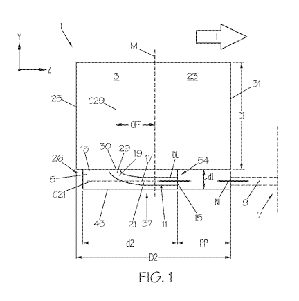
[0019] Figs. 17A and 17B illustrate diagrams examples of respective guide
features of
interface structures.
[0020] Fig. 18 illustrates a cross sectional top view of an example
illustrating an example
hook and an example secure feature of a receiving station and interface
structure,
respectively.
[0021] Fig. 19 illustrates another perspective view of an example of an
interface
structure projecting from a container side.
[0022] Fig. 20 illustrates a perspective view on an example receiving
station.
[0023] Fig. 21 illustrates a cross sectional top view on an example
interface structure
and receiving station in fluidically connected state.
[0024] Fig. 22 illustrates a cross sectional perspective view of an example
liquid supply
apparatus.
[0025] Fig. 23 illustrates a diagram illustrating an example liquid channel
and its liquid
flow path.
2
CA 03095090 2020-09-24
WO 2020/013831 PCT/US2018/041924
[0026] Fig. 24 illustrates a cross sectional top view of an example
interface structure.
[0027] Fig. 25 illustrates a front view of the example interface structure
of Fig. 24.
[0028] Fig. 26 illustrates a perspective view on an example interface
structure.
[0029] Fig. 27 illustrates a perspective view on an example key pen.
[0030] Fig. 28 illustrates a cross sectional perspective view on an example
liquid supply
apparatus.
[0031] Figs. 29 ¨ 32 illustrate front views of an example key pen in
different rotational
orientations.
[0032] Fig. 33 illustrates a diagram of an example of a base hole in a base
wall.
[0033] Fig. 34 illustrates a diagram of a cross section of an example key
pen base
portion.
[0034] Fig. 35 illustrates a front view of an example key pen.
[0035] Fig. 36 illustrates a diagram of a cross sectional front view of
another example
key pen.
[0036] Fig. 37 illustrates a diagram of a side view of an example of a key
pen.
[0037] Fig. 37A illustrates a diagram of a side view of another example key
pen.
[0038] Fig. 38 illustrates a diagram of a front view of another example key
pen.
[0039] Fig. 39 illustrates a diagram of a side view of another example key
pen.
[0040] Fig. 40 illustrates an exploded view including an example kit 100 of
components
for construing a supply apparatus.
[0041] Fig. 40A illustrates a diagram of an example unfilled reservoir.
[0042] Fig. 41 illustrates a perspective view of an example liquid supply
apparatus.
[0043] Fig. 42 illustrates a front view of an example liquid supply
apparatus.
[0044] Fig. 43 illustrates a perspective view of another example liquid
supply apparatus.
[0045] Fig. 44 illustrates a diagram of a side view of another example
liquid supply
apparatus.
[0046] Fig. 45 illustrates a diagram of a side view of yet another example
liquid supply
apparatus.
[0047]
[0048] Fig. 46 illustrates a perspective view of a plurality of example
liquid supply
apparatuses.
[0049] Fig. 47 illustrates a perspective view of an example receiving
station and liquid
supply apparatus.
3
CA 03095090 2020-09-24
WO 2020/013831 PCT/US2018/041924
[0050] Fig. 48 illustrates a diagram of a front and side view, left and
right, respectively,
of another example interface structure.
[0051] Fig. 49 illustrates a diagram of a front view of another example
liquid supply
apparatus.
[0052] Fig. 50 illustrates a diagram of a front view of yet another example
liquid supply
apparatus.
[0053] Fig. 50A illustrates a diagram of a front view of again another
example liquid
supply apparatus.
[0054] Fig. 50B illustrates a diagram of a front view of again another
example liquid
supply apparatus.
[0055] Fig. 500 illustrates a diagram of a front view of again another
example liquid
supply apparatus.
[0056] Fig. 51 illustrates a diagram of a cross sectional top view of
examples of an
interface structure and a key pen structure.
[0057] Fig. 52 illustrates a diagram of a front view of again another
example liquid
supply apparatus.
[0058] Fig. 53 illustrates a diagram of a side view of the example liquid
supply apparatus
of Fig. 52.
[0059] Fig. 54 illustrates a diagram of a side view of again another
example liquid supply
apparatus.
[0060] Fig. 55 illustrates a diagram of a front view of the example liquid
supply
apparatus of Fig. 54.
[0061] Fig. 56 illustrates a perspective view of again another example
liquid supply
apparatus in partially disassembled state.
[0062] Fig. 57 illustrates another perspective view of the example liquid
supply
apparatus of Fig. 56 in assembled state.
[0063] Fig. 58 illustrates a perspective view of again another example
liquid supply
apparatus.
[0064] Fig. 59 illustrates again a perspective view of the example liquid
supply
apparatus of Fig. 58 being installed into a corresponding receiving station.
[0065] Fig. 60 illustrates a diagram of a front view of yet another example
liquid supply
apparatus.
4
CA 03095090 2020-09-24
WO 2020/013831 PCT/US2018/041924
DESCRIPTION
[0066] This disclosure addresses print liquid supply apparatuses, interface
structures for
use with print liquid supply apparatuses, and components of print liquid
supply apparatuses
and interface structures. In operation, an interface structure of this
disclosure may be part
of a replaceable print supply apparatus and may facilitate fluidically
connecting the contents
of the supply apparatus with a host apparatus, such as a printer. Example
interface
structures of this disclosure can be associated with a relatively wide range
of different liquid
volumes, supply types, and printer platforms, whereby printer platforms may be
different in
terms of operating with different media types, media formats, print speeds
and/or liquid
types, amongst others.
[0067] The liquid referred to in this disclosure may be a print liquid. The
print liquid can
be any type of agent for printing, including ink and 3D print agents and
inhibitors. The print
liquid may include certain amounts of gas and/or solids. While this disclosure
mostly
addresses print related aspects, it is recognized that the features and
effects discussed in
this disclosure could work for other types of liquid supply apparatuses for
connection, with
other types of host apparatuses.
[0068] For example, the print liquid supply apparatus of this disclosure
can be
associated with relatively high speed or large format print systems. The
liquid reservoir
volume of the supply apparatus may be at least approximately 50 ml
(milliliters), at least
approximately 90 ml, at least approximately 100 ml, at least approximately 200
ml, at least
approximately 250 ml, at least approximately 400 ml, at least approximately
500 ml, at least
approximately 700 ml or at least approximately 1L (liter). In further
examples, the supply
apparatus may be adapted to contain larger liquid volumes, such as at least 1
L, at least 2
L, or at least 5 L. The reservoir volume of the supply apparatus of this
disclosure may be
scaled within a broad range of volumes. The same interface structure and the
same
receiving station may be associated with that broad range of volumes. The
supply of this
disclosure can facilitate using similar receiving station components for
different print system
platforms. For example, both smaller format and larger format printers, or
both 2D and 30
printers, may be equipped with a similar receiving station to interface with
the interface
structures of this disclosure. This may lead to increased customization over a
relatively
wide product range which in turn may allow for cost control, efficiency, etc.
CA 03095090 2020-09-24
WO 2020/013831 PCT/US2018/041924
[0069] Further example interface structures and supply apparatuses of this
disclosure
facilitate a relatively easy mounting and unmounting of the supply apparatus
with respect to
the receiving station, irrespective of the internal liquid volume. In again
further examples,
relatively eco-friendly supply apparatuses are provided.
[0070] In this disclosure "approximately" or "at least approximately"
should be
understood as including some appropriate margin as well as "exactly". For
example, when
referring to approximately 23 mm (millimeter) this may include a certain
margin such as for
example 0.5 mm more than or less than 23 mm, but it should also include
exactly 23 mm.
[0071] In this disclosure certain examples are described with reference to
the drawings.
While the drawings illustrate certain combinations of features, also sub-
combinations of
features that are not illustrated in isolation can be derived from these
drawings. Where
helpful reference is made to certain sub-combinations of features, margins,
ranges,
alternatives, different features, and/or omission or addition of certain
features, whereby the
drawings may be used for reference purposes.
[0072] Figs. 1 and 2 illustrate diagrams of a side and front view,
respectively, of an
example of a print liquid supply apparatus 1. The print liquid supply
apparatus 1 comprises
a container 3 to hold print liquid. In one example the container 3 includes an
at least
partially collapsible reservoir to hold the liquid. In a further example the
container 3 includes
a support structure such as a box or tray at least partially around the
reservoir to support
and/or protect the reservoir. In this disclosure, without referring to a
further reservoir or
support structure, the container includes at least a reservoir.
[0073] In a filled state, the container 3 may have a substantially cuboid
outer shape with
rectangular outer walls and sharp or rounded edges that connect the walls. The
container 3
can have other shapes. In an example the container 3 includes a collapsible
bag adapted to
collapse to facilitate withdrawal of the liquid. In the illustrated diagram
the container 3 is
illustrated in an expanded, for example filled, state. In an example, the
container 3 is void of
separate liquid retaining material such as foam. The container 3 may allow
print liquid to
freely move inside its liquid retaining volume.
[0074] The supply apparatus 1 includes an interface structure 5 for example
to provide
for a liquid connection between an internal liquid volume of the container 3
and a further
host apparatus such as a printer. The interface structure 5 includes at least
a liquid
throughput 11 supplies liquid from the container 3 to a receiving station. As
will be
explained later in some examples liquid may during certain instances in time
be provided
6
CA 03095090 2020-09-24
WO 2020/013831 PCT/US2018/041924
back to the container 3, for example due to certain pressure changes, or to
mix or circulate
liquid in the container 3, either through a single liquid throughput channel
or through
multiple throughput channels of the same interface structure 3.
[0075] In one example, a host apparatus such as a 2D or 3D printer includes
a receiving
station 7 to receive the interface structure 5. The receiving station 7 may be
a fixed or
exchangeable part of the host apparatus. The diagram of Fig. 1 illustrates a
portion of a
receiving station 7 including a liquid needle 9. In this disclosure a liquid
needle 9 may
include any fluidic needle or pen for insertion into a fluidic interface of
the supply apparatus.
For example, the fluidic needle may include a metal or plastic needle. In
other examples
other types of receiving stations may be used, having liquid interfaces other
than needles.
Other types of fluidic interfaces of a receiving station may include towers,
septums for
receiving supply-side needles. The liquid throughput 11 is adapted to connect
to the printer-
side liquid interface. The example supply apparatus 1 is to be installed and
removed with
respect to the receiving station 7. The interface structure 5 is adapted for
mounting and
unmounting with respect to the receiving station 7. In one example the
interface structure 5
is adapted for relatively user-friendly insertion and ejection with respect to
the receiving
station 7.
[0076] The interface structure 5 may include a plurality of interface
features that interact
with the receiving station. As will be explained with reference to different
examples and
figures, the interface features may include the liquid interface 15, data
processing features,
data connection features, guidance and alignment features, actuating features
to
mechanically actuate upon receiving station components, secure features, key
features,
etc. In certain examples the interface structure 5 may include a single molded
structure at
least part of which connects to, and projects from, the container 3. The
interface structure 5
may also serve as a separate cap for the container 3, to seal the container 3
during
transport and storage, after filling the container 3 with liquid before
transport.
[0077] The container 3 and interface structure 5 each have respective first
dimensions
D1, dl, second dimensions D2, d2 and third dimensions 03, d3 that extend
parallel to
perpendicular reference axes y, x, z, respectively. In this disclosure the
container
dimensions D1, D2, D3 represent (i) axes parallel to the respective reference
axes y, x, z
along which the container 3 extends, and (ii) extents of a container volume
along said axes.
In this disclosure the interface dimensions dl, d2, d3 represent (i) axes
parallel to the
respective reference axes y, x, z, and (ii) extents of an interface profile of
the interface
7
CA 03095090 2020-09-24
WO 2020/013831 PCT/US2018/041924
structure 5 along said axes, wherein the interface profile is the portion of
the interface
structure 5 which is to interface with the receiving station. It may be
understood that the
interface profile, or first dimension dl, of the interface structure 5 spans
interface
components of the interface structure 5 that are to interface with the
receiving station 7. The
interface structure may include elements that project outside of the interface
dimensions dl,
d2, d3, external to said interface profile, for example to connect to and/or
support the
container 3. Each one of the first dimensions D1, dl, second dimensions D2, d2
and third
dimensions D3, d3 may refer to a respective one of a height, length and width,
depending
on the orientation of the container 3 or interface structure 5.
[0078] In the illustrated example of Figs. 1 and 2 the first dimension D1,
dl represents a
height, the second dimension D2, d2 represents a length and the third
dimension D3, d3
represents a width of each of the container 3 and the interface structure 5,
respectively. As
a skilled person will understand, in different instances and situations, the
receiving station 7
and supply apparatus 1 may have different configurations and orientations and
that is why
this disclosure refers to "dimensions" or certain parallel "directions" or
"axes" when
describing certain features and their relative positions, dimensions and
orientations.
[0079] On the other hand, for reasons of clarity this disclosure sometimes
also uses
more orientation-dependent language such as "top view", "side view", "front
view", "back",
"bottom", "front", "top", "lateral side", "width", "height", "length",
"lateral", "distal", etc. but this
should be interpreted as intended for clarity only rather than limiting
respective features to a
particular orientation, unless explained otherwise. To illustrate this point,
certain liquid
supply apparatuses with a collapsing bag type reservoir may operate in any
orientation, due
to the nature of collapsing bag type reservoirs, whereby the interface
structure may
protrude from the container in any direction. Correspondingly, a projecting
portion of the
container may project in any direction, and the interface structure could
project in any
direction. Also, a "container bottom" may be oriented at the top of a
container if that
container is placed or mounted upside down as compared to some of the
illustrations in this
disclosure while this does not affect the functioning of the supply apparatus
or interface
structure. Also, a front of the interface structure or container may be
oriented downwards in
installed condition if the container is rotated 90 degrees with respect to the
horizontal
orientation that is illustrated in most of the figures.
[0080] Furthermore, the description may refer to virtual reference planes,
virtual planes
or planes which are meant to serve as a reference for explaining certain
shapes, relative
8
CA 03095090 2020-09-24
WO 2020/013831 PCT/US2018/041924
positions, dimensions, extents, orientations, etc. similar to the earlier
explained axes,
directions and dimensions di, 01, d2, D2, d3, D3.
[0081] The interface structure 5 projects along the direction of the first
dimension D1, dl
outwards from the container 3. In the illustration, the interface structure 5
protrudes from a
container side 13 parallel to the second and third container dimension 02, D3.
In the
illustrated example the interface structure 5 protrudes from a bottom 13 of
the container 3,
defined by a bottom wall.
[0082] In other examples, the interface structure 5 may protrude from one
of a lateral
side, front, back or top of the container 3. In different examples the supply
apparatus 1 may
have different orientations in printer-installed or stored condition whereby
the interface
structure 5 may protrude in any direction, downwards, upwards, sideways, etc.,
and the first
dimension D1, dl may be the corresponding direction.
[0083] The illustrated interface structure 5 projects outwards with respect
to the outer
wall 13 of the container 3 along a direction of the first dimension 01, dl so
that a total first
dimension 01 + di of the supply apparatus 1 can be approximately the sum of
the two first
dimensions 01, dl of the container 3 and the interface structure 5. The first
dimension D1
of the container 3 may be the distance between opposite walls along that first
dimension
01. The first dimension di of the interface structure 5 may be the distance
between
opposite sides of the projecting portion of the interface structure 5 along
said first
dimensions dl. In certain examples, the interface structure 5 is of relatively
low profile with
multiple interface components extending within the relatively low profile. The
first interface
dimension dl may be less than half of the first container dimension 01, or
less than a third,
fourth, fifth, or sixth of the first container dimension 01.
[0084] The interface structure 5 includes a liquid throughput 11 to
fluidically connect the
container to the receiving station. The liquid throughput 11 further includes
a liquid channel
17 fluidically connecting the inner volume of the container 3 with the
receiving station 7 in
installed condition. The liquid channel 17 includes a liquid interface 15 to
fluidically interface
with a counterpart liquid input interface of the receiving station 7, embodied
by a fluid
needle 9 in the example of Fig. 1. In one example the liquid interface 15
includes a seal to
receive, and seal to, the fluid needle 9. The liquid channel 17 may be defined
by at least
one liquid channel wall, for example a cylindrical or otherwise rounded
channel wall that
extends around and along at least one central axis 021 and/or 029. The liquid
channel 17
9
CA 03095090 2020-09-24
WO 2020/013831 PCT/US2018/041924
may include a needle receiving channel portion 21 and a reservoir connecting
channel
portion 29, for example with a curved intermediate liquid channel portion 19
in between.
[0085] The needle receiving channel portion 21 extends along a needle
insertion
direction NI and a main liquid flow direction DL opposite to the needle
insertion direction NI.
Central axis 021 of the needle receiving channel portion 21, interface 15 and
seal extend
along a needle insertion direction NI and a main liquid flow direction DL
opposite to the
needle insertion direction NI. The central axis 021 of the needle receiving
portion 21 may
be relatively straight along the needle insertion direction NI to facilitate
insertion of the
needle 9. In the drawing, the central axis 021, main liquid flow direction DL
and needle
insertion direction NI extend in a line.
[0086] The reservoir connecting liquid channel portion 29 may extend
approximately
parallel to the first interface dimension dl, or to a projection direction of
the interface
structure 5, as indicated by the central axis 029 of the reservoir connecting
liquid channel
portion 29. The central axes 021, 029 of the needle receiving channel portion
21 and the
reservoir connecting channel portion 29 extend at an angle with respect to
each other, for
example an approximately straight angle.
[0087] The liquid channel 17 may further include an intermediate channel
portion 19
between the needle receiving and reservoir connecting channel portions 21, 29.
The
intermediate portion 19 may inflect the channel 17 between the needle
receiving portion 21
and the reservoir connecting channel portion 29, for example in a curved
fashion, to
connect the liquid interface 15 to the inner volume of the container 3. The
intermediate
portion 19 may facilitate a curve and an offset between the needle receiving
liquid channel
portion 21 and the reservoir connecting liquid channel portion 29.
[0088] The liquid channel 17 and interface 15, including the seal 20 and
needle
receiving channel portion 21, are adapted to facilitate the illustrated main
liquid flow
direction DL out of the interface structure 5 and needle insertion direction
NI into the
interface structure 5. A main liquid flow direction DL of the needle receiving
liquid channel
portion 17 and the liquid interface 15 may extend straight out of the
interface front 54, for
example parallel to the second interface dimension d2 and/or second container
dimension
D2. The needle insertion direction NI may extend straight into the interface
front 54, for
example parallel to the second interface dimension d2 and/or second container
dimension
02. It will be understood that, in a dismounted on-the-shelve condition of the
supply
apparatus 1 the main liquid flow direction DL and needle insertion direction
NI can be
CA 03095090 2020-09-24
WO 2020/013831 PCT/US2018/041924
defined by a central axis of the needle receiving liquid channel portion 21,
which in turn may
be defined by internal walls of the needle receiving liquid channel 21 and/or
by a internal
walls or a center channel inside the seal 20. In an example where there is a
clearly
definable central axis 021 of the needle receiving liquid channel 21 and/or
liquid interface
15 including seal 20, that central axis 021 may define the main liquid flow
direction DL and
needle insertion direction NI. The main liquid flow direction DL may be
relatively straight as
determined by a central axis and/or internal liquid channel walls of the seal
20 and/or
needle receiving liquid channel portion 21 to facilitate straight entry of a
corresponding fluid
needle 9 along the respective second dimensions 02, d2.
[0089] The main liquid flow direction DL represents the course along which
the liquid is
to flow between from the container 3 to the receiving station, to print. In
one example the
liquid flows in one direction only, out of the liquid interface 15 to the
receiving station 7, at
least most of the time. In other examples, the needle 9 and liquid channel 17
may be
suitable for bi-directional flow, for example due to pressure fluctuations in
the print system
liquid circuit or for mixing/recirculating liquid in the container 3. In fact,
in some examples
two liquid interfaces may be provided in the same supply apparatus, to
interface with two
corresponding fluid needles of a single receiving station to mix/recirculate
the liquid in the
container and/or print system liquid channels. An additional dotted circle is
illustrated in Fig.
2, next to the liquid interface 15, to illustrate this possibility. Hence, in
this disclosure a main
liquid flow direction DL refers to the liquid flowing out of the supply
apparatus 1 to be able to
print using that liquid, even if the flow in the liquid channel 17 may during
certain time
instances be in the opposite direction, either in the same liquid channel or
in separate liquid
channels.
[0090] In the illustrated example, a projecting portion 23 of the container
3 projects in a
direction parallel to the main liquid flow direction DL surpassing the liquid
interface 15 in the
main liquid flow direction DL. Correspondingly, the projecting portion 23
projects in the
second container dimension 02, whereby the second container dimension 02 may
be
larger than the second interface dimension d2. The projecting portion 23
contains liquid so
that in filled condition the liquid may be held above, or next to, and beyond
the liquid
interface 15. In certain examples, more than one third or more than half of
the second
container dimensions 02 may project beyond the liquid interface 15 in the main
liquid flow
direction DL. This may facilitate that the container projecting portion 23 can
be inserted
11
CA 03095090 2020-09-24
WO 2020/013831 PCT/US2018/041924
head first into a receiving station 7 before a sealed and operational
connection between the
receiving station 7 and the interface structure 5 is established.
[0091] In certain examples, the extent PP to which the projecting portion
23 of the
container 3 surpasses the liquid interface 15 may determine the reservoir
volume of the
container 3, whereby in a plurality of supply apparatuses 1 that have
different volumes that
connect to the same receiving station, the first and third dimensions dl D1,
d3, D3 are the
same but the second container dimension may vary. A relatively large liquid
volume
reservoir of the container 3 may be associated with a longer projecting
portion 23.
[0092] Some of these features may facilitate readily connecting a liquid
volume size of
choice to a receiving station 7. By a ready push against a back 25 of the
container 3, in an
insertion direction I parallel to the main liquid flow direction DL, the
supply apparatus 1 can
be pushed into a fluidically connected state with the receiving station 7. In
addition, a
manufacturer can adapt the inner volume of the container 3 by scaling the
projecting portion
23 while the ease of insertion of the supply apparatus 1 is the same because
the back 25
and interface structure 5 are positioned the same between these different
volumes. In
certain examples, the projecting portion 23 protrudes into the receiving
station 7 so that the
back of the supply apparatus 1 does not protrude from the receiving station 7,
thereby
preventing obstacles that operators could otherwise bump into. In the example
of Fig. 1 a
back 25 of the container 3 extends a small distance Bb further than a back 26
of the
interface structure 5, as measured along the second container dimension D2.
For example,
such distance Bb may be between approximately 0 and 1 or between approximately
0 and
1 cm.
[0093] Where the projecting portion 23 projects beyond the liquid interface
15, for
example where the liquid volume is more than 100 ml, the interface structure 5
may be
fluidically connected to the container 3 offset from a middle M of the second
container
dimension D2 by an offset distance, for example of more than 5 mm or several
cm (cm)
depending on the liquid volume of the container 3. Herein, the middle M may be
defined by
a virtual reference plane that is parallel to the first and third container
dimension D1, D3 and
in the middle of the second container dimension D2. In the illustrated
example, the middle
M of the second container dimension D2 extends in the middle between a front
31 and back
25 of the container 3, and the reservoir connecting portion 29 of the liquid
channel 17
connects to the internal reservoir volume of the container 3 behind the middle
M, between
the middle M and the back 25 of the container 3. As illustrated, the reservoir
connecting
12
CA 03095090 2020-09-24
WO 2020/013831 PCT/US2018/041924
portion 29 of the liquid channel 17 of the interface structure 5 is connected
to a liquid output
30 of the container 3 to facilitate throughput of liquid from the container 3
through the
interface structure 5. Correspondingly, the fluid connection between the
container liquid
output 30 and the reservoir connecting portion 29 of the liquid channel 17 is
provided
between the middle plane M and the back 25 of the container 3.
[0094] Fig. 3 illustrates a diagram of a side view of an example of a print
liquid supply
apparatus 1 wherein the container 3 includes a bag-in-box type structure. In
the illustrated
state, a reservoir 33 is illustrated that is substantially empty and
collapsed. The reservoir 33
has air and vapor barrier walls to inhibit vapor exiting and air entering the
reservoir 33. In
the illustrated state, most or all liquid has been withdrawn from the
reservoir 33 that has
collapsed accordingly, in a relatively random fashion. In the illustrated
example the
reservoir 33 is a substantially completely flexible bag but in other examples
the reservoir
could have some rigid portions. The reservoir 33 may be rigid near the output
30 to facilitate
connection with the interface structure 5.
[0095] In an example the container 3 further includes a support structure
35 at least
partially around the reservoir 33, for example to support and protect the
reservoir 33. The
support structure 35 may also to facilitate relatively rough guiding of the
supply apparatus 1
into the receiving station 7. In again other examples, the support structure
35 may facilitate
stacking, storage, and presentation of usage, brand and contents information.
In a filled
state the reservoir 33 may occupy most of the inner volume of the support
structure 35. For
example, the outer volume of the reservoir 33 in a filled state may be more
than 60%, more
than 70%, more than 80% or more than 90% of the inner volume of the support
structure
35. For example, the same reservoir 33 having a predefined volume capacity may
be used
for different support structures 35 of different volumes. For example, the
reservoirs 33 may
be filled partly or completely depending on the inner volume of the support
structure 35. For
example, the reservoir 33 can be filled with less than 90%, less than 80%,
less than 70%,
less than 60%, less than 50%, less than 40% or even lower percentages of its
maximum
volume capacity. For example, while a reservoir 33 may have a maximum capacity
of 2 L,
that same 2L reservoir may be only partially filled and seated in a support
structure 35
having a maximum capacity of less than 2L, such as 500 ml or 1 L, whereby a
supply
apparatus 1 of 500m1 or a supply apparatus 1 of 1L is provided, respectively.
[0096] As can be seen from Fig. 4, which is diagrammatic top view on an
example
supply apparatus 1 along the first container dimension D1 and interface
structure projection
13
CA 03095090 2020-09-24
WO 2020/013831 PCT/US2018/041924
direction, the interface structure 5 and its interface components may extend
within an area
or contour defined by an outer volume of the container 3, for example as
defined by the
outer walls 25, 31, 51. The illustrated outer walls 25, 31, 51 extend
approximately parallel to
the first container dimension D1, in the illustrated filled state of the
container 3. In the
illustrated example, the second and third interface dimension d2, d3 are less
than the
corresponding second and third container dimension D2, 03, whereby the second
and third
container dimension D2, D3 overlap the second and third interface dimension
d2, d3 as
seen in directions perpendicular to the respective second and third
dimensions.
[0097] In an example the support structure 35 may be made of carton or
other suitable
material, such as for example other cellulose based material or plastics. In
certain
examples, the support structure material include corrugated cardboard and/or
fiberboard.
The support structure 35 may be relatively rigid as compared to the at least
partially
collapsible reservoir 33, for example to provide support, protection and stack-
ability to the
reservoir 33. The interface structure 5 is relatively rigid to facilitate
relatively precise guiding
with respect to the receiving station 7, for example, more rigid than the
support structure 35.
The interface structure 5 may include relatively rigid molded plastics. In one
example liquid
flow components of the reservoir 33 and interface structure 5 are relatively
fluid
impermeable, that is liquid, vapor and air impermeable, as compared to the
support
structure 35. The impermeability of the interface structure 5 facilitates its
capping function.
The supply apparatus 1 may be opened by opening, removing, rupturing, etc.,
the seal of
the interface structure.
[0098] In an example, the interface structure 5 includes at least one
straight guide
surface 41, 43 to slide the interface structure 5 along corresponding
receiving station
surfaces to facilitate installation of the container 3 in the receiving
station 7, as illustrated by
Figs. 1 and 2. The at least one straight guide surface 41, 43 may be elongate
in the
direction of, and extend approximately parallel to, the second dimension D2,
d2 of the
interface structure 5 and the container 3. The at least one straight guide
surface 41, 43 may
comprise opposite lateral guide surfaces 41 at external lateral sides or side
walls 39, each
lateral guide surface extending approximately parallel to the first and second
interface
dimension dl, d2. The at least one straight guide surface 41, 43 may comprise
an
intermediate guide surface 43 at a distal side 37, the intermediate guide
surface extending
opposite to the side 13 of the container 3 from which the interface structure
5 projects, and
between the lateral sides 39. In the illustrated example, the distal side 37
defines a bottom
14
CA 03095090 2020-09-24
WO 2020/013831 PCT/US2018/041924
of the interface structure 5. The intermediate guide surface 43 may be
approximately
parallel to the second and third interface dimension d2, d.
[0099] The lateral and intermediate guide surfaces 41, 43 may be relatively
flat. The
lateral and intermediate guide surfaces 41, 43 may be relatively elongate
along the
direction of the second interface dimension d2, along at least a portion of
the interface
structure 5, at least sufficiently elongate to facilitate confining the
movement of the supply
apparatus to the second interface dimension d2 and positioning the liquid
interface 15. The
guide surfaces 41, 43 of the interface structure 41, 43 may be defined by
relatively flat,
flush and elongate outer surfaces of the interface structure 5 to facilitate
sliding in a
direction along the second interface dimension d2 and positioning of the
liquid interface 15
in respective direction along the first and third interface dimension dl d3.
In one example
the third interface dimension d3 extends between the external lateral guide
surfaces 41. In
one example, the second interface dimension d2 may be defined by the length of
the
intermediate guide surface 43 from the front to the back of the interface
structure 5.
[00100] In this example, the lateral guide surfaces 41 are adapted to (i)
guide the
liquid interface 15 in a direction along the second interface dimension d2 and
the main
liquid flow direction DL, and (ii) facilitate positioning of the liquid
interface 15 along an axis
parallel to the third interface dimension d3 by limiting the degree of freedom
of the interface
structure 5 in the receiving station 7 in the opposite directions parallel to
the third interface
dimension d3. The intermediate guide surface 43 is adapted to (i) guide the
liquid interface
15 in a direction along the second interface dimensions d2 and the main liquid
flow direction
DL, and (ii) to facilitate positioning of the liquid interface 15 along an
axis parallel to the first
interface dimension dl by limiting the degree of freedom of the interface
structure 5 in the
receiving station 7 in at least one direction of the first interface dimension
dl. In the
example where during installation the interface structure 5 projects downwards
from the
bottom 13 the intermediate guide surface 43 may include a horizontal surface
to facilitate
vertical positioning of the liquid interface 15 with respect to the liquid
input interface of the
receiving station 7, by sliding over a corresponding horizontal bottom guide
surface of the
receiving station. To that end the intermediate guide surface 43 may extend at
a
predetermined distance from a central axis CP21 of the needle receiving liquid
channel
portion 21. The intermediate guide surface 43 may span a substantial portion
of the distal
side 37 of the interface structure 5, along the second and third interface
dimensions d2, d3,
CA 03095090 2020-09-24
WO 2020/013831 PCT/US2018/041924
whereby the first interface dimension dl may extend between the side 13 of the
container 3
from which the interface structure 5 projects and the intermediate guide
surface 43.
[00101] Figs. 5 and 6 illustrate perspective views of examples of sets of
different
volume print liquid supply apparatuses 101 and corresponding receiving
stations 107. Fig. 7
illustrates any of these print supply apparatuses 101 installed in one of
those receiving
stations 107. Figs. 8 and 9 illustrate a single, similar, example supply
apparatus 101 in side
and front view, respectively. Features, functions and definitions disclosed
with reference to
Figs. 1 ¨ 4 may similarly apply to the examples explained with reference to
Figs. 5 ¨ 9.
[00102] In one example, the volumes of the four supply apparatuses 101 of
Figs. 5
and 6, from the smaller to the larger supply apparatuses 101, that is, from
front to back in
Fig. Sand from left to right in Fig. 6, are 100, 200, 500 and 1000 ml,
respectively. The
interface structures 105 of the different illustrated supply apparatuses 101
have
approximately the same dimensions dl, d2, d3 and some of the same interface
components, except for certain differences such as for example key pen
orientations and
data stored on integrated circuits. The different volume supply apparatuses
101 have
different container volumes, wherein the first and third container dimensions
D1 and 03 are
approximately the same, yet the second container dimensions D2 are different.
Each
container 103 is associated with a different liquid volume capacity and a
different projecting
length PP of the projecting portions 123. The illustrated example containers
103 include a
box-shaped support structure 135 of folded carton or the like, and an inner
collapsible
reservoir. For example, the support structure 135 includes corrugated
cardboard and/or
fiberboard. Note that while the support structures 135 may provide for
different volumes and
second container dimensions D2, the reservoirs inside the support structures
may be of the
same desian, as in having the same maximum capacity, but with different fill
amounts, for
example a fill amount approximately corresponding to the respective support
structure
volume.
[00103] In Figs. 5 and 6, each interface structure 105 projects from the
bottom 113 at
an equal distance from the back 125 of the container 103, for example
relatively close to
the back 125. As illustrated in Fig. 8 a distance between a back 126 of the
interface
structure 105 and the back 125 of the container 103 along the second dimension
02, d2 of
the container 103 and the interface structure 105, as defined by the distance
between
virtual reference planes over said backs 125, 126 parallel to the first and
third dimension
D1, dl, D3, d3, can be approximately 0 mm, or for example less than 1 cm. As
illustrated in
16
CA 03095090 2020-09-24
WO 2020/013831 PCT/US2018/041924
Fig. 8, the backs 125, 126 of the container 103 and the interface structure
105 could be
approximately flush with respect to each other. In other examples the back 125
of the
container 103 may extend further backwards than the back 126 of the interface
structure
105 whereby the distance can be slightly larger than 0 mm, such as 1 ¨5 mm, or
substantially larger than 0 mm, such as greater than 1 cm, see for example the
diagrammatic examples of Fig. 44 and 45. In another, different example the
back 126 of the
interface structure 105 could protrude from the container back 125 whereby
again there
may be a distance between said backs 125, 126 greater than 0 mm but in the
opposite
direction as explained before.
[00104] Each different volume supply apparatus 101 of Figs. 5 and 6 has a
different
container 103 with a different second container dimension D2, that is, a
different length PP
of the projecting portion 123 along the second container dimension D2, wherein
the length
PP of the projecting portion 123 may be defined by the extent in which the
second container
dimension D2 projects beyond an edge 116 of a liquid interface 115 and/or
interface front
154, in the main liquid flow direction DL (Fig. 8).
[00105] The smaller supply volumes, for example of 100 ml or less such as
the front
supply apparatus 101 of Fig. 5 and the corresponding one in Fig. 6, may have a
second
container dimension D2 of similar length as the second interface dimension d2,
or even
less, where there is no or hardly any projecting portion 123 that projects
beyond the
interface edge 116, as indicated by reference number 123b. Hence, the
projecting length
PP of the container 103 may be zero or is relatively small. Larger volumes,
for example
greater than 100 ml as illustrated by the other supply apparatuses of Fig. 5
and the
corresponding ones in Fig. 6, may have a second container dimension D2 that is
greater
than the second interface dimension d2. In certain examples, the second
container
dimension can be at least two times or at least three times the second
interface dimension
d2. In these examples the extent PP of the projecting portion 123 is greater
than the second
interface dimension d2. These different container volumes and projection
extents PP may
be associated with substantially the same interface structures 105 and
substantially the
same receiving stations 107. Also, the same reservoir bag capacity may be used
for the
different volumes and different support structures 135 but with different fill
grades.
[00106] In a substantially horizontal orientation of the supply apparatus
101, the
interface structure 105 may protrude from the bottom 113 of the box, near a
back 125 of the
box, and the box projects over the interface structure 105 towards the front,
beyond a liquid
17
CA 03095090 2020-09-24
WO 2020/013831 PCT/US2018/041924
interface 115 of the liquid output, whereby for the different examples the
projection extent
PP determines the maximum liquid volume capacity of the container 103.
[00107] The third interface dimension d3 may be defined by the distance
between the
external lateral sides 139, as defined by lateral side walls 139a, and the
third container
dimension D3 may be defined by the distance between outer surfaces of opposite
lateral
sides 151 of the container 103. In the illustrated examples, the width of the
supply
apparatuses 101 is determined by the third container dimension D3. The width
is relatively
small, providing for a relatively thin aspect ratio of the supply apparatuses
101, which in
turn may facilitate a small foot print of the collection of receiving stations
in a single printer,
while being connectable to a relatively large supply volume range. In the
illustrated
examples, the third interface dimension d3 is slightly less than the third
container dimension
03. For example, the third interface dimension d3 is approximately 80 ¨ 100%
of the third
container dimension D3, for example approximately 85 ¨ 100%, or for example
approximately 90¨ 100%. The third interface dimension d3 may be between
approximately
30 and 52 mm, for example between approximately 48 and 50 mm. Correspondingly
the
third container dimension 03 may be greater such as between 30 and 65 min, or
between
45 mm and 63 mm, or between 50 and 63 mm. The third container dimension D3
could be
varied depending on the internal width of the receiving station 107 and/or the
pitch between
adjacent receiving stations 107. In other examples the third container
dimension D3 could
be substantially larger than the third interface dimension d3 (see for example
Fig. 46).
[00108] One example effect of the container 103 projecting in the main
liquid flow
direction DL, beyond the liquid interface 115, is that it facilitates
consistent and relatively
user-friendly mounting and unmounting of different supply apparatuses 101 of a
relatively
large range of volumes, including relatively large volumes. In the prior art,
these large
volume supplies can be relatively cumbersome to handle or install to the
printer. In addition,
printer OEMs sometimes have different supply designs to handle different
liquid volumes for
different platforms but in the present example, the supply apparatuses can be
mounted and
unmounted by a relatively simple push at the back 125, in the direction of the
main liquid
flow direction DL. As illustrated in Fig. 7, the back 125 may extend
approximately in line
with the receiving opening edge of the receiving station, again facilitating a
ready push to
the back 125 into the receiving station to mount and unmount the supply
apparatus 101.
Also, the liquid interface 115 is still relatively close to the back which may
facilitate
increased user control at installation, for positioning with respect to a
liquid needle of the
18
CA 03095090 2020-09-24
WO 2020/013831 PCT/US2018/041924
receiving station. Different, relatively long projection extents PP need not
affect the
robustness and ease of installation. In fact, in certain examples the
projecting portion 123
may facilitate some pre-alignment of the supply apparatus 101 the receiving
station 107.
[00109] The supply apparatus 101 of the present example allows for a first
rough
alignment to the receiving station 107 when placing the projecting portion 123
of the
container 103 in the receiving station 107, and then a second, more precise
alignment
using the interface structure guide and/or key features, that may engage
corresponding
guide and/or key features of the receiving station, which will further align
the liquid
interfaces. Such stepped alignment may prevent damage to receiving station
components
such as the fluid needle, which could otherwise be easily damaged due to
repetitive
connection of heavy large volume supply apparatuses.
[00110] The extent of the projecting portion of the interface structure 105
is
represented by the first interface dimension dl. In this example, the first
interface
dimension dl may be measured between said the container side 113 from which
the
interface structure 5 projects and an external or distal side 137 of the
interface structure
105, for example between proximal and distal front edges (e.g. respectively
represented by
154b and 154c in Fig. 10) of the interface structure 105 at opposite sides of
the liquid
interface 115. In this example the external or distal side 137 is defined by a
support wall
137a parallel to the second and third interface dimensions d2, d3 that also
includes the
intermediate guide slot 144.
[00111] The first interface dimension dl can be at least six times smaller
than the first
container dimension Dl. In the illustrated orientation this corresponds to a
projecting height
of the interface structure 105 being at least six times less than the height
of the container
103. This provides for a relatively large liquid volume container 103 combined
with a
relatively low-profile interface structure 105, facilitating further
volumetric efficiency, for
example for on-the-shelf storage and transport, as well as for the print
system with the
supply apparatus installed. Also, a relatively small low-profile interface
structure 105 may
be more suitable for relatively smaller liquid volumes and relatively smaller
printers. For
example, the first container dimension D1 is at least 6 cm and the first
interface dimension
dl of the projecting portion of the interface structure 105 is 20 mm or less.
For example, the
first container dimension D1 is at least 9 cm and the first interface
dimension dl is 15 mm
or less. For example, the first container dimension D1 is at least
approximately 9.5 cm and
the first interface dimension dl is approximately 13 mm or less.
19
CA 03095090 2020-09-24
WO 2020/013831 PCT/US2018/041924
[00112] For example, the profile height of the interface structure 105 may
be the first
interface dimension di and the distance over which the interface structure 105
projects
from the respective container side 113, when assembled to the container 103.
The low-
profile height of the interface structure 105 may refer to a relatively small
first dimension dl
of the interface structure 105 and the interface structure representing a
relatively small
projection from the container 103. The profile height may span several
interface
components including the needle receiving portion 121 (e.g. see Fig. 11) of
the liquid
channel 117, the liquid interface 105, the key pens 165, the integrated
circuit 174, and the
edge 154b of a front push area 154a. For example, also a secure feature 157 at
an external
lateral side of the respective key pen 165, that includes at least one of a
clearance 159 and
stop surface 163, may extend within the profile height, or first dimension dl,
of the interface
structure 105. The reservoir connecting liquid channel portion 129 may project
outside of
the profile height, into the container 103 when assembled to the container
103. There may
be more projecting components of the interface structure 105 that project
outside of the
profile height, for example for attachment to the container, support to the
receiving station,
or for other purposes.
[00113] In an example the width (d3) of the interface structure 105 may be
approximately 49 mm and the width (D3) of the container 103 may be
approximately 58
mm. The height (di) of the interface structure 105 may be approximately 12 mm
and the
height (D1) of the box may be approximately 10 cm. Hence, a total aspect ratio
of the first
dimensions D1 + dl and third dimensions D3 of the supply apparatus 101 may be
112: 58,
which could be rounded to approximately 2 : 1 or 11 : 6. The length (d2) of
the interface
structure, perpendicular to said height and width, may be approximately 43 mm,
and the
length (D2) of the box may be equal or more depending on said projection
extent PP.
[00114] As said, example supply apparatuses 101 of this disclosure have a
relatively
thin aspect ratio. Hence, in one example the aspect ratio of the second
container dimension
D2 versus the third container dimension D3 is at least 1 : 2, at least 1 : 3
or at least 1 : 4,
that is, the second container dimension D2 can be at least two, three or four
times greater
than the third container dimension D3 wherein the second container dimension
02 may
correspond to a length and the third container dimension D3 may correspond to
a width.
[00115] In one example an aspect ratio of the first dimension D1 versus the
third
dimension D3 of the container 103 is at least 3: 2 or at least 5: 3 or at
least approximately
11 : 6. In a further example the aspect ratio of the total first dimension (or
height) of the
CA 03095090 2020-09-24
WO 2020/013831 PCT/US2018/041924
supply apparatus, which may be the sum of the first container dimension D1 and
the first
interface dimension dl, versus the third dimension D3 of the container 103 (or
width of the
supply apparatus) is at least approximately 2: 1. In some of the larger volume
supply
apparatuses 101 with a similar thin aspect ratio the container 103 may have a
relatively
long shape whereby the aspect ratio of the first container dimension D1 versus
the second
container dimension D2 is 1 : 1 or less, or 2 : 3 or less, 1 : 2 or less, or 1
: 3 or less,
whereby smaller ratios refer to smaller first dimensions D1 relative to
greater second
dimensions D2.
[00116] As illustrated in Figs. 8 and 9 the interface structure 105 may
project from a
side 113 in a direction parallel to the first dimension Di of the container
103 wherein the
interface dimensions d2, d3 are smaller than the container dimensions D2, D3
so that the
interface structure 105 extends within a contour formed by the second and
third container
dimensions D2. D3, similar to the example of Fig. 4.
[00117] The liquid output of the interface structure 105 includes a liquid
channel 117.
The liquid channel includes a liquid interface 115. The liquid interface 115
is provided at the
downstream end of the liquid channel 117 along a main direction of flow. In
Fig. 9 a center
plane OP of the container 103 and interface structure 105 is illustrated, that
may serve as a
virtual reference plane. The center plane OP may extend approximately through
a middle of
the third dimension D3, d3 of the container 103 and/or interface structure
105. The center
plane OP extends parallel to the first and second dimensions D1, dl D2, d2, of
the
container 103 and interface structure 105, whereby the liquid interface 115 is
laterally offset
from the center plane OP of the interface structure 105 in one direction along
the third
interface dimension d3. Integrated circuit contact pads 175 are laterally
offset from the
center plane OP in the other direction along the third interface dimension d3,
which is the
opposite side of the center plane OP with respect to the liquid interface 115.
Note that, in
other examples a plane parallel to the first and second dimensions D1, dl, 02,
d2, and
between the liquid interface 115 and contact pad array 175, need not be
exactly through the
center of the supply apparatus.
[00118] In an example, a first recess 171a is provided laterally next to
the needle
receiving liquid channel portion 121 and houses a key pen 165, and a second
recess 171b
is provided at the other lateral side of the needle receiving liquid channel
portion 121 and
houses another key pen 165 and the integrated circuit contact pads 175. The
recesses
171a, 171b may have entrances at each lateral side of the liquid interface 115
and interface
21
CA 03095090 2020-09-24
WO 2020/013831 PCT/US2018/041924
structure front surface 154, whereby the front surface 154 may be part of a
liquid channel
block extending between the recesses 171a, 171b, through which the liquid
channel 117
extends. The recesses 171a, 171b have a depth along the container side 113
from which
the interface structure 105 projects. The key pens 165 protrude parallel to
the second
interface dimension d2.
[00119] Figs 10, 11 and 12 illustrate interface components of the interface
structure
according to certain examples. Fig. 10 is a diagrammatic amplification of an
example liquid
interface 115 and a front push area 154b of an interface structure front 154
as also
illustrated in Fig. 9, and Figs. 11 and 12 illustrate cross sectional top
views of portions of the
interface structure 105 and receiving station 107, in a disconnected and
connected stage of
interface components, respectively.
[00120] In an example the liquid interface 115 includes a seal 120 to seal
the channel
117 around a fluid needle at insertion. The seal 120 may be of elastomer
material. The seal
120 may include a central internal channel along its central axis and along
the needle
insertion direction NI, through which the needle protrudes in installed
condition. The seal
120 can be a plug to be plugged into internal walls of the liquid interface
115 and needle
receiving liquid channel portion 121, to extend along a length of the
interface 115 and
channel portion 121. The seal 120 may sit in a cylindrical or round fitting in
an interface
front 154 of the interface structure 105. The seal 120 may be sealed with
respect to the
liquid channel 117 and interface edge 116 by swaging. For example, during
manufacture, a
seal plug or other seal 120 is inserted into the liquid channel 117 after
which a protruding
ridge 118 of the edge 116 is pushed into a mushroom-like profile by an
ultrasonically
vibrating tool. The inner edge of the lip of the profile then retains the seal
120 and may also
provide pressure to the seal 120 to obtain sufficient fluid tightness. In
addition, or instead,
adhesive and/or welding may be applied for establishing a proper seal
structure in the
interface structure 105.
[00121] The seal 120 may include a breakable membrane 122 at its center,
for
example downstream of its central internal channel, that is configured to open
when a
needle is inserted for the first time. The needle may pierce the membrane 122
at insertion.
The needle receiving liquid channel portion 121, seal 120, membrane 122, and
edge 116
may be centered around a single central axis, which for the purpose of
illustration can be
indicated in Fig. 8 by main liquid flow direction DL. The depth of the seal
120 extends along
that central axis and the seal 120 is adapted to seal to the inserted needle,
along said
22
CA 03095090 2020-09-24
WO 2020/013831 PCT/US2018/041924
central axis. In certain instances, the seal 120 may, in use, push a humidor
112 of the fluid
needle. The seal 120 and membrane 122 inhibit fluid/vapor transfer to seal the
container
103 during transport or on the shelf life of the supply apparatus 101, as well
as seal to the
needle during needle insertion. Instead of a pierceable membrane 122, the seal
120 could
also include any suitable plug, label, membrane or film or the like, adhered,
welded,
attached or integrally molded to the seal 120, for example for tearing,
removing or piercing,
that covers the internal channel of the seal 120 at the downstream end for
sealing the
container and liquid channel before usage. A separate lid or plug could be
provided, or
other measures, to seal the liquid channel 117 during transport and storage.
[00122] In this example, an edge 116 of the liquid interface 115 extends
around the
seal 120. The seal 120 is inserted in the liquid interface 115 and needle
receiving channel
portion 121 of the liquid channel 117. The seal 120 may partly lie against
said edge 116.
The edge 116 may be round and extend around a central axis of a similarly
round needle
receiving channel portion 121 and seal 120. The edge 116 may be part of the
front 154 of
the interface structure adjacent and around the liquid interface 115. In one
example the
edge 116 may be flush with the rest of the front 154 while in other examples
the edge 116
may include a protruding ridge 118, before or after manufacture. In the
example illustrated
in Figs. 9 - 12, the ridge 118 represents a state before swaging wherein the
ridge 118
protrudes sufficiently to be swaged against and/or around the seal 120,
whereby the ridge
118 relatively flatter after said swaging, which is not illustrated in this
drawing.
[00123] The interface front 154 and/or edge 116 may form an extreme of the
second
interface dimension d2. Front edges of walls 139a, 137a that define the
respective lateral
sides 139 and/or distal side 137 may extend at the same level as the interface
front 154,
forming a circumferential interface front edge, that may serve as respective
entrances to the
recesses 171a, 171b. The interface front 154, adjacent and/or partially around
the interface
edge 116 may, in use, push against a protective structure 110 of the needle.
In different
examples a protective structure of the needle may include a shutter, plate,
sleeve, sled or
the like.
[00124] The illustrated example protective structure 110 includes a plate
or sleeve to
protect the fluid needle against mechanical damage, and may be retracted with
respect to
the needle by a pushing force of the interface front 154 against the
protective structure
when inserting the supply apparatus 101. In the illustrated example the
protective structure
110 that protects the needle is separate from the humidor 112 whereby the
protective
23
CA 03095090 2020-09-24
WO 2020/013831 PCT/US2018/041924
structure 110 may be moved by the interface front 154, for example a push area
154a of
the front 154, and the humidor 112 can be moved separately by the protective
structure 110
and/or the interface 115. The humidor 112 may be adapted to keep the liquid
needle wet
and/or avoid leaking. In other example receiving stations the protective
structure 110 and
humidor 112 could be moved together as a single connected structure. In again
other
example receiving stations only one of a protective structure 110 and humidor
112 is
provided. The front push area 154a can be used to push against the humidor 112
in
addition to, or instead of the protective structure 110, to release the needle
109.
[00125] In the illustrated example, the interface front 154 extends between
the
recesses 171a, 171b. A distal edge 154c of the front extends further out
towards the lateral
sides to define the entrance of the recesses 171a, 171b, between the interface
front 154
and the lateral sides 139. The interface front 154 extends at least partially
around, and
adjacent to, the liquid interface 115. The interface front 154 may be a
straight surface at an
approximately straight angle with the main liquid flow direction DL, parallel
to the first and
third interface dimension di, d3.
[00126] The interface front 154 includes a push area 154a, which may be
defined by a
wall portion located between the liquid interface edge 116 and the container
103, at least
when the interface structure 105 is assembled to the container 103. The wall
portion that
defines the front push area 154a may be part of a structure that is integrally
molded with the
liquid channel wall 117b, that protrudes from the support wall 137a with the
recesses 171a,
171b on either side (e.g. see Fig. 26). The push area 154a includes and
terminates on an
outer edge 154b of the front 154 of the interface structure 105, that in the
illustrated
example terminates on the container side 113. The push area 154a is adapted to
force the
protective structure 110 backwards during insertion and/or in installed
condition. The push
area 154a may extend at least partially between the liquid interface edge 116
and the
container 103. In certain examples indents, channels or recesses could be
provided
between the liquid interface edge 116 and the push area edge 154b, into the
front 154,
whereby the push area 154a may consist of only the edge 154b, which may be
sufficient to
serve as the push area to abut the protective structure 110 (e.g. see Fig.
48).
[00127] The interface structure 105 may be of relatively low profile.
Hence, in one
example a height HO of the push area 154a, along the first interface dimension
dl, wherein
said height HO represents a smallest distance between the liquid interface
edge 116 and
the container 103 or interface front edge 154b, is less than the inner
diameter D116 of the
24
CA 03095090 2020-09-24
WO 2020/013831 PCT/US2018/041924
liquid interface edge 116, or less than the outer diameter of the seal 120
when plugged into
the outlet interface 115, for example the height HO is less than half of one
of said diameters
D116. Said inner and outer diameter may be the same so that any one or both of
these
diameters could serve as a reference to indicate the relatively small height
of the push area
154a and in turn, the relatively low-profile height of the interface structure
105. For clarity,
the liquid interface edge 116 may be defined by the transition between (i)
plastic walls of
the needle receiving portion 121 of the liquid channel 117 and (ii) the
surface of the
interface front 154. In some examples it may be difficult to determine what is
exactly the
liquid interface edge 116 because that edge may be rounded. In such examples
the outer
diameter of a plugged portion of the seal 120 in plugged condition, at a point
near the
interface front 154 but within the liquid channel 117, may be used. For
example, said height
HO of the push area 154a between said edges 116, 154b is equal to or less than
approximately 6 mm, equal to or less than approximately 5 mm, equal to or less
than
approximately 4 mm, or equal to or less than approximately 3 mm. For example,
in a
relative sense, the height HO of the interface front push area 154a may be
less than half of
the diameter of said liquid outlet interface edge 116. A relatively small
interface front push
area 154a may be sufficient to move the protective structure with respect to
the needle,
while still facilitating a relatively low-profile interface structure. For
example, the push area
154a need not be a flat front wall but could instead comprise only an edge
(e.g. front edge
154b) or rounded shape, sufficient to push the protective structure 110 to
release the
needle.
[00128] In the example of Fig. 11, the interface front 154 initiates
pushing the
protective structure 110 backwards with respect to the needle 109 to expose
the needle
109 to facilitate insertion of the needle 109 into the liquid interface 115.
For example, first
the push area 154a of the interface front 154 pushes the protective structure
110, and then
the protective structure 110 itself, or the front 154 or seal 120 pushes the
humidor 112. The
latter is illustrated in Fig. 12, wherein the interface structure 105 has
moved in the direction
of the liquid output DL as compared to the position of Fig. 11, whereby the
protective
structure 110 and humidor 112 have been moved backwards with respect to the
needle 109
by the push area 154a, thereby extracting the needle 109. In fig. 12, the
needle 109 has
pierced the seal membrane 122, and a fluidic connection between the liquid
channel 117
and the needle 109 has been established.
CA 03095090 2020-09-24
WO 2020/013831 PCT/US2018/041924
[00129] In one example, the distal side 137 spans the extent of the third
interface
dimension d3. A support wall 137a of the interface structure 105 may define
the distal side
137. The support wall 137a may be partly to guide and support the supply
apparatus 101 in
the receiving station, for example through its intermediate guide surfaces
143, 143b, 147,
which may form part of the support wall 137a. A portion of the support wall
137a may
support the integrated circuit 174. A relatively shallow cut out may be
provided in the
support wall 137a to seat the integrated circuit 174. For example, the shallow
cut out may
be less than 2 or less than 1 mm deep. The support wall 137a may have a distal
front edge
154c opposite to the push area front edge 154b, along the third interface
dimension d3, the
first interface dimension dl extending between these opposite front edges
154b, 154c.
[00130] The view of Fig. 11 exposes integrated circuit contact pads 175
laterally next
to the liquid interface 115 and in a respective recess 171b. The pads 175 are
arranged on a
line parallel to the third interface dimension d3 and in a virtual reference
plane parallel to
the second and third interface dimension d2, d3. In an example, the contact
pads 175 are
arranged on one side of the center plane CP, while the liquid interface 115,
or the center
axis of the liquid interface 115, is arranged on the opposite side of the
center plane CP.
During connection, as illustrated by Fig. 12, a data connector 173 of the
receiving station
107 passes into the recess 171b to connect to the integrated circuit contact
pads 175.
[00131] Figs. 13 and 14 illustrate an example of an interface structure 105
protruding
from a respective container 103, in perspective and front view, respectively.
The interface
structure 105 may be the same as the interface structure 105 illustrated in
one of Figs. 5 ¨
12. Fig. 15 illustrates an example of a detail of an intermediate guide of the
interface
structure 105 of Figs. 13 and 14. Fig. 16 illustrates and example of a detail
of a lateral guide
of the interface structure 105, near a front side of the interface structure
105, and a secure
feature 157.
[00132] In the examples illustrated in Figs. 13- 16, the interface
structure 105
includes lateral guide features 138 at its external lateral sides 139 and
intermediate guide
features 140 at its distal side 137. Fig. 17 illustrates how the lateral and
intermediate guide
features 138, 140, respectively, may be connected to corresponding lateral and
intermediate guide rails 138A, 140A, respectively, of the receiving station
107. Fig. 17 also
illustrates how the container support wall 113 and outer lateral walls 151 may
receive rough
guidance from corresponding walls of the receiving station 107.
26
CA 03095090 2020-09-24
WO 2020/013831 PCT/US2018/041924
[00133] As can be seen from Fig. 13, the guide features 138, 140 may be
relatively
elongate, for example extending along at least 1, 2, 3 or 4 cm of the second
interface
dimension d2, for example at least 50% or at least 75% or most or all of the
length of the
second interface dimension d2. The guide features 138, 140 are to guide the
interface
structure 105 with respect to the receiving station, to align the fluidic
interfaces. For
example, the receiving station could include corresponding lateral guide rails
138A and/or
an intermediate guide rail 140A (Fig. 17, 20). Note that, in other examples,
key pens 165
could be used for guidance purposes instead of, or in addition to, at least
one of the guide
features 138, 140.
[00134] In the illustrated example, the lateral guide features 138 include
first and
second lateral guide surfaces 141, 141b, 145 at angles with respect each
other. As will be
explained, the first and second lateral guide surfaces 141, 141b, 145 define a
lateral guide
slot 142 in the side 139. The lateral side walls 139a may include at least one
first lateral
guide surface 141, 141b to facilitate positioning the liquid interface 115
with respect to a
liquid needle of the receiving station in a direction parallel to the third
interface dimension
d3 and/or at least one second lateral guide surface 145 to facilitate
positioning the liquid
interface 115 with respect to the needle of the receiving station in a
direction parallel to the
first interface dimension dl. Accordingly, in an example where the supply
apparatus 101 is
installed approximately horizontally, the at least one first lateral guide
surface 141, 141b
may facilitate horizontal positioning of the liquid input 115 and the at least
one second
lateral guide surface 145 may facilitate vertical positioning.
[00135] The first lateral guide surfaces 141, 141b may extend approximately
parallel
to the first and second interface dimension dl, d2. The first lateral guide
surfaces 141, 141b
may be substantially flat in a plane approximately parallel to said first and
second interface
dimension dl, d2, wherein approximately parallel may for example include 10
degrees or
less deviation from absolutely parallel. The first lateral guide surfaces 141,
141b may be
elongate along the second interface dimension d2, that is, relatively long
along the second
interface dimension d2 and relatively short along the first interface
dimension dl. Where
during installation of the supply apparatus 101 the interface structure 105
projects
downwards from the bottom 113, the first lateral guide surfaces 141, 141b may
facilitate
approximately horizontal positioning of the liquid interface 115 with respect
to a liquid input
of the receiving station.
27
CA 03095090 2020-09-24
WO 2020/013831 PCT/US2018/041924
[00136] A single lateral side wall 139 may have a plurality of first
lateral guide surfaces
141, 141b at a plurality of levels along the third interface dimension d3. The
lateral guide
feature 138 may include two outer first lateral guide surfaces 141 and an
inner first lateral
guide surface 141b that is offset in an inwards direction along the third
interface dimension
d3 with respect to the outer first lateral guide surfaces 141. The inner first
lateral guide
surface 141b may extend between two outer first lateral guide surfaces 141.
The inner and
outer first lateral guide surfaces 141, 141b may span the first interface
dimension dl , at
least approximately. In certain examples only an inner first lateral guide
surface 141b
without the outer first lateral guide surfaces 141, or only one inner and one
outer first lateral
guide surface 141, 141b may be provided, which can be sufficient for
positioning the liquid
interface 115 along the first and/or third interface dimension dl, d3. In
other examples only
one first inner or outer lateral guide surface 141, 141b may be sufficient to
serve the
purpose of guiding and positioning, for example together with an intermediate
guide feature
140. In yet other examples, only one of the lateral and intermediate guide
features 138, 140
is provided.
[00137] In the illustrated orientation the support wall 137a defines the
bottom of the
interface structure 105. The support wall 137a may include an intermediate
guide feature
140, for example adjacent the liquid interface 115. The intermediate guide
feature 140 may
include at least one first intermediate guide surface 143, 143b, to facilitate
positioning the
liquid interface 115 with respect to the liquid needle while limiting freedom
of movement in a
direction along the first interface dimension dl and/or at least one second
intermediate
guide surface 147, to facilitate positioning the liquid interface with respect
to the liquid
needle while limiting freedom of movement in a direction along the third
interface dimension
d3. The at least one first intermediate guide surface 143, 143b may extend
parallel to the
second and third interface dimension d2, d3. The at least one second
intermediate guide
surface 147 may extend parallel to the first and second interface dimension
dl, d2
[00138] In one example first intermediate guide surfaces 143, 143b include
an inner
intermediate guide surface 143b, which may extend inwards with respect to the
outer
surface of the distal side 137, and two outer intermediate guide surfaces 143
which may
define the outer surface of the distal side 137. Hence, the first intermediate
guide surfaces
143, 143b may extend over multiple levels along the first interface dimension
dl. The inner
first intermediate guide surface 143b is adapted to receive and slide over a
counterpart
guide of the receiving station. The inner first intermediate guide surface
143b may be flat
28
CA 03095090 2020-09-24
WO 2020/013831 PCT/US2018/041924
along a plane approximately parallel to said second and third interface
dimension d2, d3.
The inner first intermediate guide surface 143b may be relatively narrow and
of elongate
shape, that is, relatively long along the second interface dimension d2 and
relatively short
along the third interface dimension d3.
[00139] The inner first intermediate guide surface 143b may extend between
two outer
first intermediate guide surfaces 143. The inner first intermediate guide
surface 143b may
extend adjacent the liquid interface 115 to facilitate positioning of the
interface 115 with
respect to the needle 109. The inner and outer first intermediate guide
surfaces 143, 143b
may together span a substantial portion of the third interface dimension d3,
at least
approximately. In certain examples only an inner first intermediate guide
surface 143b,
without the outer first intermediate guide surfaces 143, or only one inner and
one outer first
lateral guide surface 143, 143b may be provided, which can be sufficient for
positioning the
liquid interface 115 along the first interface dimension dl.
[00140] Where during installation of the supply apparatus 101 the interface
structure
105 projects downwards from the bottom 113, the first intermediate guide
surface 143,
143b may facilitate vertical positioning of the liquid interface 115 with
respect to the liquid
input of the receiving station and the first lateral guide surfaces 141, 141b
may facilitate
horizontal positioning of the liquid interface 115.
[00141] In the illustrated example, the lateral side 139 further includes
at least one
second lateral guide surface 145 at at least one of the external lateral sides
of the interface
structure 105, for example a pair of opposite second lateral guide surfaces
145 at each
lateral side, to limit the degree of freedom of the interface structure 105 in
a direction along
the first interface dimension di. The second lateral guide surfaces 145 can be
adjacent to
and at an angle with the at least one first lateral guide surface 141, 141b.
Said angle can be
approximately straight but need not be exactly straight, for example to
provide for lead in,
manufacturing tolerance or other reasons whereby the angle between the first
and second
lateral guide surfaces 141, 145 could be between approximately 80 and 100
degrees. The
at least one second lateral guide surface 145 can be provided between and
along the
opposite outer first lateral guide surfaces 141 of the same lateral side 139.
The at least one
second lateral guide surface 145 can be provided along the inner first lateral
guide surface
141b. The second lateral guide surfaces 145 may extend approximately parallel
to the
second interface dimension d2 and third interface dimension d3 but need not be
exactly
29
CA 03095090 2020-09-24
WO 2020/013831 PCT/US2018/041924
parallel to achieve said function of limiting the freedom of movement in a
direction along the
first interface dimension dl.
[00142] For example, the second lateral guide surfaces 145 may be
substantially flat,
for example along a plane approximately parallel to the second and third
interface
dimension d2, d3, wherein approximately parallel may include a 10 degrees
deviation from
absolutely parallel. The second lateral guide surface 145 may be elongate,
that is, relatively
long along the second interface dimension d2 and relatively short along the
third interface
dimension d3. As can be best seen in Fig. 16, lead-in ramps 155 can be
provided near the
front entrance of the second lateral guide surfaces 145.
[00143] A pair of opposite second lateral guide surfaces 145 may extend
along and on
both sides of the inner first lateral guide surface 141b, for example so that
the pair of
second lateral guide surfaces 145 and the inner first lateral guide surface
141b together
form a lateral guide slot 142. In another example the slot may extend through
the side wall
139 without the inner first lateral guide surface 141b. The outer first
lateral guide surfaces
141 may extend at the outsides of the slot 142 parallel to the first interface
dimension di.
The second lateral guide surfaces 145 and the first lateral guide surfaces
141, 141b at the
opposite lateral sides 139 may facilitate guiding and translating the
interface structure 105
in a direction along the second interface dimension d2 while limiting
translations and
rotations along and around other axes. The first 141, 141b and/or second
lateral guide
surfaces 145 may span a significant portion of the second dimension d2 of the
interface
structure 105, such as at least 50%, at least 75% or most or all of the second
dimension d2.
One or more openings or interruptions can be provided in the guide surfaces
141, 145,
such as said lead in ramp 155 or clearances 159.
[00144] In other examples, a clearance slot may be provided at the lateral
side 139 to
clear a corresponding guide rail to facilitate the interfaces structure 105 to
be inserted into
the receiving station 107 without guidance by the guide rail. In such
examples, guidance, if
any, may be obtained through walls of the support structure 135 and/or other
sides or
edges of the interface structure 105 and/or key pens 165. Such clearance slot
may be
defined by opposite edges of the lateral side 139, or between a respective
lateral edge and
the container side 113 from which the interface structure 105 projects.
[00145] The intermediate guide feature 140 may be provided with at least
one second
intermediate guide surface 147 to position the interface structure 105 with
respect to the
receiving station 107 while limiting a freedom of movement of the interface
structure 105 in
CA 03095090 2020-09-24
WO 2020/013831 PCT/US2018/041924
a direction along the third interface dimension d3. The second intermediate
guide surface
147 may be at an angle with respect to the first intermediate guide surfaces
143, 143b. For
example, such angle could be approximately straight, wherein some margin or
tolerance
may be included. For example, the angle could be between approximately 80 and
100
degrees. A pair of opposite second intermediate guide surfaces 147 may be
provided
forming a slot 144. The second intermediate guide surfaces 147 may be
substantially flat,
for example along a plane approximately parallel to the first and second
interface dimension
dl, d2 wherein approximately parallel may include a 10 degrees or less
deviation from
exactly parallel. The second intermediate guide surface 147 may be of
relatively elongate
and narrow shape, that is, relatively long along the second interface
dimension d2 and
relatively short along the first interface dimension dl.
[00146] The pair of opposite second intermediate guide surfaces 147 may
extend at
both sides and along the inner first intermediate guide surface 143b so that
the inner first
intermediate guide surface 143b and the second intermediate guide surfaces
together form
an intermediate guide slot 144 in the support wall 137a of the interface
structure 105.
However, the intermediate guide slot 144 may extend further inwards without
the inner first
intermediate guide surface 143b. The outer first intermediate guide surfaces
143 may
extend at both sides of the slot 144 parallel to the third interface dimension
d3.
[00147] In another example (not illustrated), an intermediate clearance
slot is provided
at the distal side 137 but the slot is to clear a corresponding guide rail to
facilitate the
interfaces structure 105 to be fully inserted into the receiving station 107
while avoiding
guidance along a corresponding guide rail. For example, as compared to Fig.
14, opposite
edges of a clearance slot may correspond to second intermediate guide surface
147
whereby the distance between opposite edges of the clearance slot may be
greater than
the distance between the opposite second intermediate guide surfaces 147.
Guidance, if
any, may be obtained through walls of the support structure 135 of other sides
or edges of
the interface structure 105.
[00148] In one example, the intermediate guide feature 140 or the clearance
slot is
intersected by a virtual reference plane PO parallel to the first and second
interface
dimension dl, d2, whereby the plane PO extends between a center of the liquid
interface
115 and a respective key pen 165, while integrated contact pads 175 extend at
another
lateral side of the liquid interface 115 opposite to the plane PO.
31
CA 03095090 2020-09-24
WO 2020/013831 PCT/US2018/041924
[00149] As best seen in Fig. 14 and 15, one second intermediate guide
surface 147 of
the pair of second intermediate guide surfaces 147, that is closer to the
liquid channel 117
and/or interface 115, may be shorter along the first interface dimension dl
than the
opposite second intermediate guide surface 147 of said pair. The second
intermediate
guide surface 147 that is closer to the needle receiving liquid channel
portion 121 may be
narrower to facilitate a thick enough liquid channel wall 117b (Fig. 22).
Accordingly, in the
illustrated example the intermediate guide slot 144 may include a chamfer 148
in its cross
section, between the first and second intermediate guide surfaces 143b, 147,
respectively,
and along at least part of the length of the guide surfaces 143b, 147,
adjacent and parallel
to the liquid channel 117, to facilitate space for the channel walls without
impeding the
guiding and liquid interface positioning function of the intermediate guide
feature 140.
Hence, the intermediate guide feature 140 may include approximately
perpendicular guide
surfaces 143b, 147, including a pair of opposite approximately parallel guide
surfaces 147,
perpendicular to an inner guide surface 143b, wherein said chamfer 148 defines
a third
guide surface that extends between, and at an angle with, one of the parallel
guide surfaces
147 and the inner guide surface 143b, adjacent to and along the liquid channel
117.
[00150] The above-mentioned guide features 138, 140 and/or surfaces 141,
141b,
143, 143b, 145, 147 may be elongate in a direction of the second interface
dimension d2,
and/or flat and flush, to facilitate installation of the interface structure
105 with respect to
respective straight counterpart guides of the receiving station. Some of or
all the above-
mentioned guide surfaces 141, 141b, 143, 143b, 145, 147 may be provided to
facilitate
guiding and translating the interface structure 105 along an axis parallel to
the needle
insertion direction NI while limiting translations and rotations along and
around other axes,
to align and fluidically connect the liquid interface 115 to the at least one
needle 119. In one
example the interface structure may include only one or two of each of the
illustrated lateral
and intermediate guide features 138, 140, respectively. In one example, at
installation,
predominantly the second lateral guide surfaces 145 are used for alignment of
the interface
structure 105 along the first dimension dl, D1 and predominantly the second
intermediate
guide surfaces 147 are used for alignment along the third dimension d3. D3,
whereby in a
sub-example at least one of the other, that is first lateral and first
intermediate, guide
surfaces 141, 141b, 143, 143b need not engage the receiving station guide
surfaces or rails
138A, 140A at installation or could be omitted from the interface structure
design 105. In a
further example the lateral and/or intermediate guide feature 138, 140 may
include only one
32
CA 03095090 2020-09-24
WO 2020/013831 PCT/US2018/041924
or two respective second lateral or intermediate guide surfaces 145, 147
without the first
lateral or intermediate guide surfaces 141, 141b, 143, 1431o, which in certain
instances may
be sufficient for guiding and positioning. In again other examples respective
guide features
138, 140 and/or guide slots 142, 144 may include edges which need not be
exactly flat and
straight surfaces where the edges may be elongate along the second interface
dimension
d2.
[00151] In an example the first lateral guide surfaces 141, 141b are
approximately
parallel to the second intermediate guide surfaces 147. In an example the
first lateral guide
surfaces 141, 141b and/or the second intermediate guide surfaces 147 are
approximately
parallel to outer lateral walls 151 of the container 3. In an example the
first intermediate
guide surfaces 143, 143b are approximately parallel to the second lateral
guide surfaces
145. In an example the first intermediate guide surfaces 143, 143b and/or the
second
lateral guide surfaces 145 are approximately parallel to the side 113 of the
container 103
from which the interface structure 105 projects, and/or to an opposite side
132 of the
container 103 opposite to the side 113 from which the interface structure 105
projects.
Some of these aspects may facilitate a first rough alignment of the container
103 followed
by a more precise alignment of the interface structure 105, as explained
earlier.
[00152] To facilitate proper engagement one or each guide feature 138, 140
may be
provided with lead-in features. For example, as illustrated in Fig. 16, the
lateral guide
feature 138 includes a lateral lead-in feature 153 near at a front level (in
this view indicated
by 154) of the interface structure 105 to lead in the rest of the guide
feature 138 with
respect to an external guide rail. In the illustrated example lead-in ramps
155 are provided
at the front of both lateral guide slots 142. The lead-in ramps 155 are
defined by opposite
diverging lateral guide surfaces, diverging from back towards the front level
of the interface
structure. The lead-in ramps 155 are a bended or inclined surface with respect
to the
trailing portion the lateral guide feature 138. The trailing portion includes
the second lateral
guide surfaces 145 that may be contiguous with the ramps 155. The lead-in
ramps 155 may
be at an angle with respect to the first lateral guide surface 141, 141b, for
example at an
approximately straight angle, or for example between approximately 80 and 100
degrees
with respect to the first lateral guide surface 141, 141b. In an example only
one lateral lead-
in ramp 155 is provided at one lateral side 139.
[00153] A relatively fine alignment may be facilitated by the guide
surfaces 141, 141b,
143, 143b, 145, 147 of the interface structure 105, for example with the aid
of
33
CA 03095090 2020-09-24
WO 2020/013831
PCT/US2018/041924
corresponding guide rails and/or surfaces of the receiving station. In a
stepped yet relatively
fluent fashion, the projecting portion 123 may first engage to the receiving
station, providing
for relatively rough alignment, then the lead-in features 153 may engage, and
then the
guide features 138, 140 may provide for a finer alignment. For example, the
lateral lead-in
and guide features 153, 138 may provide for first fine alignment while the
intermediate
guide feature 140 may again allow for a finer alignment. Hence, a proper
insertion of the
needle with relatively low risk of breaking the needle may be established. The
intermediate
guide feature 140 extends adjacent to, and along, the liquid interface 115 and
channel 117,
to facilitate the relatively precise insertion of the needle. The intermediate
guide feature 140
may be connected to the guide rails after the other guide features 138 are
connected to
provide a final and finest alignment. In certain instances, the liquid volume
and associated
weight of the supply apparatus 101 can be relatively high which would increase
a risk of
breaking a fluidic needle, especially in case of relatively uncontrolled push
insertion, but this
does not need to impede the supply apparatus 101 of some of the examples of
this
disclosure to readily slide into a relatively precise fluidic connection with
the receiving
station. In again other examples, some but not all of the disclosed guide
features 138, 140
are provided and some user control is required for establishing the fluidic
connection.
[00154] Fig.
17A illustrates a diagram of the guide features 138, 140 of the interface
structure 105, in a diagrammatic front view, wherein the guide features 138,
140 are
adapted to limit the freedom of movement in directions along the third
interface dimensions
d3. For example, the guide features to limit the freedom of movement in a
direction along
the third interface dimension d3 include at least one of (i) the inner first
lateral guide
surfaces 141b, (ii) the outer first lateral guide surfaces 141b, and (iii) the
second
intermediate guide surfaces 147. In one example each of those surfaces 141,
141b, 147
may be relatively elongate in the second interface dimension d2 and may be
defined by a
ridge or flat surface that engages guide surfaces of the receiving station. A
distinction can
be made between guide features that limit movement in one direction along the
third
interface dimension d3 and guide features that limit movement in the opposite
direction
along the third dimension d3, which is illustrated by continuous lines versus
dotted lines in
Fig. 17A. In one example the interface structure 105 includes at least two
guide surfaces to
limit movement in one direction along the third interface dimension d3 (e.g.
141, 141b, 147
in dotted lines) and at least two guide surfaces to limit movement in the
opposite direction
along the third interface dimension d3 (e.g. 141, 141b, 147 in continuous
lines).
34
CA 03095090 2020-09-24
WO 2020/013831
PCT/US2018/041924
[00155] Fig.
176 illustrates a diagram of the guide features 138, 140 of the interface
structure 105, in a diagrammatic front view, wherein the guide features 138,
140 are
adapted to limit the freedom of movement in directions along the first
interface dimensions
dl. For example, the guide features to limit the freedom of movement in a
direction along
the first interface dimension dl include at least one of (i) the second
lateral guide surfaces
145, (ii) the first inner intermediate guide surfaces 143b, and (iii) the
first outer intermediate
guide surfaces 143. In one example each of those surfaces 145, 143b, 143 may
be
relatively elongate in the second interface dimension d2 and may be defined by
a ridge or
flat surface that engages guide surfaces of the receiving station. In Fig.
176, a distinction
can be made between guide features that limit movement in one direction along
the first
interface dimension dl and guide features that limit movement in the opposite
direction
along the first interface dimension dl, which is illustrated by continuous
lines versus dotted
lines. In one example the interface structure 105 includes at least two guide
surfaces to limit
movement in one direction (e.g. 145, 143, 143b in continuous lines) and at
least two guide
surfaces to limit movement in the opposite direction (e.g. 145 in dotted
lines). In one
example the interface structure may be provided with lateral guide surfaces
145 that are
adapted to limit movement of the interface structure 105 in a direction
opposite to the
projection direction of the interface structure 105, at least when in contact
with
corresponding lateral guide rails.
[00156] Fig.
18 illustrates a cross sectional top view of a system where an example
interface structure 105 is connected to a receiving station. The example
interface structure
105 includes a secure feature 157, as also illustrated in Figs. 8 and 16. The
secure feature
157 may facilitate operational installation, and in some instances, retention,
of the supply
apparatus to the receiving station.
[00157] In
these drawings, the secure feature 157 includes a clearance 159, here in
the form of an opening through the lateral wall that defines the lateral side
139, into which a
corresponding secure element of the receiving station 107 may project, wherein
the secure
element may be a catch or detente wherein the secure element may be a catch or
detent.
For example, one secure feature 157 can be provided at one lateral side 139,
or two secure
features 157 can be provided at opposite lateral sides 139. The clearance 159
may be
provided near a front side of the interface structure 105, next to the key pen
165. In the
illustrated example the protruding secure element is a catch hook 161.
However, depending
on the application, secure elements other than hooks may be used to facilitate
securing the
CA 03095090 2020-09-24
WO 2020/013831 PCT/US2018/041924
supply apparatus to the receiving station. The secure elements may include
blocking
features, as is the case for the illustrated hook 161, audible or tangible
feedback features,
trigger or switch features, etc. That is, while in one example the secure
element may
directly lock an interface structure to the receiving station, in other
examples the secure
element may only trigger a switch or provide for some feedback functionality.
[00158] In the illustrated example, the secure feature 157 is provided in
the lateral
guide feature 138. The clearance 159 may be defined by a cut out in the
lateral side 139,
for example in the slot 142 and/or through the inner first lateral guide
surface 141b. In the
illustrated example, the clearance 159 is a through hole in the respective
side wall, opening
into the respective recess 171a, 171b. In other examples, instead of a through
hole the
clearance 159 could be an indent. Each lateral side 139 may include a secure
feature 157,
to interact with secure elements at both sides 139. The clearance 159 may
facilitate that a
biased secure element 161 can project partially into the clearance 159
[00159] The secure feature 157 may further include a stop surface 163,
hereafter also
referred to as stop, next to the clearance 159. The stop 163 can be defined by
an edge of
the clearance 159 at a side of the clearance 159 that is near the front edge
of the interface
structure 105. The stop 163 is provided near a front level of the interface
structure as
indicated by 154 in Fig. 16, for example next to a distal portion of the key
pen 165. The stop
163 may be part of a lateral front wall portion 141b that defines the stop as
well as an edge
of the front of the interface structure 105, at the entrance of the respective
recess. The stop
surface 163 may extend at an angle with respect to the adjacent surface of the
respective
wall portion 141b of the lateral side 139. In one example system, the stop 163
provides for
resistance against moving the interface structure 105 with respect to the
secure element. In
another example system, the stop 163 and/or lateral front wall portion 163a
may push a
finger, trigger or switch or the like to switch into a certain operational
mode or to provide
certain feedback.
[00160] As seen in Fig. 16 a front lateral side wall portion 163a may
extend between,
and define, the stop 163 and the edge around the front. The front lateral side
wall portion
163a may extend next to a distal portion of the key pen 165, providing for
some protection
of the key pen 165 against breaking by falling. The front lateral side wall
portion 163a may
extend between the lead-in ramps 155.
[00161] In the illustrated example of Fig. 18 the secure element is a hook
161. The
hook 161 is shown in a position whereby it projects through the clearance 159.
As will be
36
CA 03095090 2020-09-24
WO 2020/013831 PCT/US2018/041924
explained below, this position of the hook 161 can be imposed by a key pen 165
that
pushes an actuator of the receiving station that in turn triggers a the hook
161 through a
mechanism arranged to transmit the translation to the hook, hereafter referred
to as
transmission mechanism. In the illustration, some distance is shown between
the hook 161
and the stop 163, which illustrates a moment of installation where the supply
apparatus 101
is pushed fully into the receiving station just before the operator manually
releases the
supply apparatus 101 for completing the insertion. After such release a
pushing force of a
biased spring will move the stop 163 against the hook 161 in an outward
direction out of the
receiving station. Thus, the hook 161 counteracts the opposing force F (Fig.
21) of that
spring, blocking removal or ejection of the supply apparatus 101 whereby the
supply
apparatus 101 is retained in fluidic connection. Subsequent retraction of the
hook 161
would automatically eject the supply apparatus 101.
[00162] A second manual push against the back 125 of the supply apparatus
101
pushes the key pen 165 against the actuator, which may again trigger said
transmission
mechanism to release the hook 161 with respect to the stop 163 and clearance
159,
whereby the hook 161 is pulled out of the clearance 159. Thereby, the
interface structure
105 is unblocked, which causes the biased spring to expand and push the
interface
structure 105 out of the receiving station 105.
[00163] The stop surface is the stop portion against which a part of the
hook 161 is to
engage. That engagement surface of the stop 163 may be relatively flat and
extend at an
angle a with respect to the respective lateral side surface 141b, for example
at an angle a
of at least approximately 90 degrees, or slightly more than 90 degrees, for
example at an
angle a of at least approximately 91 degrees. An angle a of more than 90
degrees may
allow for additional retention of the hook 161, inhibiting slipping of the
hook 161 with respect
to the stop 163, or at least inhibit unintended disengagement of the hook 161
to some
extent to avoid unintended ejection of the interface structure 105.
[00164] Other example supply apparatuses may not have a secure feature. In
one
example the receiving station may have a hook, grip or arm or the like that
retains the
supply apparatus 101 against a back of the apparatus. In another example, the
supply
apparatus 101 is installed to a receiving station in a hung condition (e.g.
see Fig. 43)
whereby the fluidic connection may be sufficiently secured by the weight of
the supply itself,
or by manual retention, or by an under-pressure created by a printer pump
between the
37
CA 03095090 2020-09-24
WO 2020/013831 PCT/US2018/041924
liquid interfaces. In again other examples, the supply apparatus may include a
clearance or
clearance slot to clear both the guide rail and hook of the receiving station.
[00165] Other example supply apparatuses may apply other types of secure
features
than the explained secure feature 157. These other type secure features may
suitably
retain a fluidic connection between the supply apparatus and liquid input. For
example, the
supply apparatus 101 may be provided with a similar secure feature 157 but at
a different
location, for example at the distal side 137 of the interface structure 105.
For example, the
supply apparatus may be provided with a hook, grip or click finger, to hook or
unhook to a
receiving station, or with high friction surfaces such as elastomeric cushions
to press-fit to
walls of the receiving station.
[00166] Fig 19 illustrates an example interface structure 105 in a
perspective view,
projecting from a respective side 113 of the container 103. Fig. 20
illustrates part of an
example receiving station 107 for the example interface structure 105. A
humidor 112 has
been omitted in this drawing. Fig. 21 illustrates a cross-sectional top view
of an example
where the interface structure 105 and the receiving station 107 are in secured
and fluidically
connected condition. Amongst others, certain functions and features related to
protruding
key pens 165 of certain examples of this disclosure will be explained with
reference to
these figures 19 - 21.
[00167] The key pens 165 of this disclosure may have a generally
longitudinal shape,
for example protruding along a longitudinal axis Ck for at least approximately
10, at least
approximately 12, at least approximately 15, at least approximately 20 or at
least
approximately 23 mm. In a first, broader definition of this disclosure a key
pen has a
"keying" function because it is to pass through a printer key slot to act upon
an actuator, for
example a switch and/or transmission. In a further example a key pen also has
a liquid type
(e.g. ink color or agent) discriminating function because it allows for
connection to a
corresponding receiving station with a matching key slot, while it may be
blocked from
connection to receiving stations with non-matching key slots. In other
examples the key pen
may be adapted to have the discriminating function without necessarily having
the actuating
function. As will be clarified with reference to various example drawings
throughout this
disclosure, the key pen may have different shapes, ranging from relatively
simple protruding
pins up to shapes with more complex cross sections.
[00168] In the illustrated examples, the interface structure 105 comprises
a pair of key
pens 165. The key pens 165 extend within the second interface dimension d2, as
defined
38
CA 03095090 2020-09-24
WO 2020/013831 PCT/US2018/041924
by opposite external lateral sides 139. Correspondingly, the key pens 165
extend within the
container dimension 02. A pair of key pens 165 may facilitate distribution
and/or balancing
of forces to actuate respective secure elements as compared to a single key
pen. The
corresponding actuators that are actuated by the key pens 165 may receive the
actuation
force in a balanced or distributed manner. Opposite key pens 165 may
facilitate better
guidance and/or alignment of the interface structure 105 and liquid interface
115. More than
two key pens could be provided, for example with more than one key pen at
either side of
the liquid channel 117. The interface structure 105 may also include a pair of
secure
features 157, each secure feature at a respective lateral side 139 next to
each key pen 165.
In other examples the interface structure 105 comprises only a single key pen
165 or more
than two key pens 165.
[00169] The key pens 165 may protrude from a base 169, for example a base
wall.
The base 169 may be a wall, foot or column. For example, the base 169 may be a
wall or
foot at a deep end of a respective recess 171a, 171b within which the key pen
165
protrudes. The base 169 may be offset in a direction backwards, along the
needle insertion
direction NI, with respect to the interface front 154.
[00170] The key pen 165 may extend approximately parallel to the second
interface
dimension d2. The key pen 165 may extend approximately parallel to the
respective side
113 the container 103 from which the interface structure 105 projects, for
example below a
bottom of the container 103. The container side 113 can be relatively planar
and the key
pens 165 may extend parallel to that side 113. In Figs. 19- 21, the at least
one key pen 165
protrudes along its longitudinal axis Ck that is approximately parallel to the
needle insertion
direction NI, main liquid flow direction DL, second interface dimension d2
and/or second
container dimension 02. The longitudinal axis Ck of the key pen 165 may
represent an axis
along which the key pen protrudes. The longitudinal axis Ck may be a central
axis of the
key pen 165. The key pens 165 extend next to, at opposite sides of, the liquid
channel 117
and/or liquid interface 115, for example generally along a longitudinal
direction
approximately parallel to a central axis of the needle receiving portion 121
of the liquid
channel 117 and/or a central axis of the seal 120.
[00171] A distance between a first key pen 165 and the needle receiving
liquid
channel portion 121, along the third interface dimensions d3, may be greater
than a
distance between an opposite second key pen 165 and the needle receiving
liquid channel
portion 121. The distance could be defined by a distance between an axis
representing the
39
CA 03095090 2020-09-24
WO 2020/013831 PCT/US2018/041924
needle insertion direction NI and a longitudinal axis Ck along which the key
pens 165
extend. The integrated circuit 174 and/or contact pads 175 thereof extend
between the first
key pen 165 and the needle receiving liquid channel portion 121. Said greater
distance
facilitates a data connector 173 to pass between the first key pen 165 and
molded structure
of the front push area 154a and the liquid channel wall 117b.
[00172] The key pen 165 is adapted to be inserted in a corresponding key
slot 167 of
the receiving station 107 (Ha. 20). The key slot 167 may be adapted to
facilitate blocking
non-corresponding key pens 165 to prevent that non-matching print liquids are
connected
to the receiving station 107, for example to prevent contaminating the liquid
needle 109 or
further liquid channels downstream of that needle 109 with a non-compatible
liquid type. In
the example of Fig. 20 the key slot 167 has the shape of a Y in a
predetermined orientation,
intended to receive only key pens 165 having a correspondingly shaped cross
section and
corresponding orientation. Other key slots 167 could for example have T-, V-,
L-, l-, X- or
one or multiple dot shapes or other geometrical shapes.
[00173] In certain examples, master key pens may be provided that can
connect to
different key slots 167, even if the purpose of these key slots is to
discriminate between key
pens. Master key pens may be provided for service fluid supplies or simply as
alternative
solutions to color discriminating key pens, and in this disclosure also fall
within the definition
of a "key pen".
[00174] The key pens 165 may be adapted to actuate upon corresponding
actuators
of associated key slot components. Suitable actuators of a receiving station
may include
electrical switches and/or mechanical transmission mechanisms. In the example
of Fig. 21,
the actuator is a transmission mechanism including a spring-loaded rod 179.
[00175] As illustrated in Fig. 21, a distal actuating surface area 168 of
the key pen 165
passes through the key slot 167 to actuate upon the rod 179 at insertion of
the interface
structure 105 into the receiving station 107. The rod 179 at least partially
extends inside a
key slot housing component 170 here embodied by a sleeve-shaped housing. At
insertion
of the supply apparatus 101 into the receiving station 107, for example by a
push of an
operator, the housing component 170 is inserted into the recess 171a, 171b,
through the
recess entrance at the front of the interface structure, towards the base.
Thereby the key
pen 165 is inserted into the housing component 170 and pushes the rod 179. In
the
illustrated example, the corresponding movement of the rod 179 along the main
liquid flow
direction DL is transmitted to the hook 161 by a suitable transmission
mechanism (not
CA 03095090 2020-09-24
WO 2020/013831 PCT/US2018/041924
shown), whereby an end of the hook 161 is inserted into the clearance 159.
Once the hook
161 is inserted into the clearance and the supply apparatus is released by the
operator, the
hook 161 may engage the stop 163, retaining the supply apparatus 101 in the
receiving
station 107. The hook 161 may retain the interface structure 105 in seated
condition against
the spring force F of the rods 179. In the seated condition, the needle 109
protrudes inside
the liquid channel 117 and seal 120, opening a ball valve 120A and
establishing liquid flow
between the supply apparatus 101 and the receiving station 107. Also, a data
connector
173 is connected to the integrated circuit contact pad array 175 whereby data
communication may be established. The interface structure 105 may include
secure
features 157 at both lateral sides 139, each with clearances 159 and stops
163.
Correspondingly, two opposite hooks 161 may be triggered through the pair of
rods 179.
[00176] A subsequent push of the operator again moves a rod 179 which again
transmits its actuation to the hook 161. Thereby, the hook 161 is released
from the
clearance 159 and stop 163, triggering ejection of the supply apparatus 101.
At ejection, the
rod 179 pushes the key pen 165 backwards inside its rod housing component 170
by
decompression of the spring, whereby the fluid needle 109 exits the liquid
interface 115 and
the data connection is broken.
[00177] In the illustrated example, the interface structure 105 includes
two recesses
171a, 171b both laterally next to the needle receiving portion 121 of the
liquid channel 117,
having a depth along the second interface dimension d2. The recesses 171a,
171b may
surround the key pens 165, for example to facilitate intrusion of the key pens
165 into
respective key slot housing components 170.
[00178] The recess 171a, 171b may be defined by recess walls. The recess
171a,
171b may extend next to the needle receiving liquid channel portion 121, and
on the other
side the recess 171a, 171b can be delimited by the inner wall surface of the
respective
lateral side 139 of the interface structure 105. The recess 171a, 171b may
further be
delimited by, on one side, the side 113 of the container 103 from which the
interface
structure 105 projects, and, on the opposite side, the inner wall surface of
the distal side
137.
[00179] The liquid interface 115 and needle receiving channel portion 121
can be
laterally offset from a center plane CP of the interface structure 105 (e.g.
see also Figs. 24
and 25), whereby a smaller and larger recess 171a, 171b, respectively, are
provided at
both sides of the interface 115 and needle receiving channel portion 121. One
key pen may
41
CA 03095090 2020-09-24
WO 2020/013831 PCT/US2018/041924
extend at a greater distance from the liquid channel than the other key pen,
with an
integrated circuit extending between said one key pen and the liquid channel.
In one
example, the larger recess 171b houses the integrated circuit contact pads
175, that
extends on the other side of the center plane OP with respect to the liquid
interface 115.
The recess 171b may house the entire integrated circuit 174 of which the pads
175 are a
part. The integrated circuit 174 can be a microcontroller or other customized
integrated
circuitry. The integrated circuit contact pads 175 may extend over an inner
wall portion of
the distal side 137 of the interface structure 105, in a plane parallel to the
second and third
interface dimension d2, d3 and along an axis parallel to the third interface
dimension d3.
The distal side 137 includes a support wall portion for the integrated circuit
174. The
integrated circuit contact pads 175 may extend between the liquid channel 117
and the
respective key pen 165. During installation of the supply apparatus 101 a data
connector
173 for the integrated circuit contact pads 175 may pass into the respective
larger recess
171b, between the needle receiving channel portion 121 and the respective key
pen 165
housed by the respective recess 171b.
[00180] The key pen 165 may have an elongate shape in a direction along the
second
interface dimension d2, for example along its longitudinal axis Ck, protruding
from the base
169 of the recess 171a, 171b. In one example, the extent of protrusion KL from
the base
169 may be based on (i) a desired insertion length of the liquid needle, (ii)
an insertion
length of the data connector 173, and (iii) an actuator push length for
sufficiently triggering
the actuator. In an example, the key pen 165 protrudes inside the respective
recess 171a,
171b along the second interface dimension d2, without surpassing the liquid
output edge
116 whereby the actuating surface area 168 of the pen 165 may be approximately
at level
with the liquid output edge 116. In one example, each protruding key pen 165
is housed in
the respective recess 171a, 171b between the walls 117b adjacent to the liquid
channel
117, and walls that define the lateral side 139. The depth of the recess 171a,
171b,
between the interface front 154 and the base 169 along the second interface
dimension d2,
may be approximately the same as the length of the key pen 165, as measured
between
that base 169 and a distal actuating surface area 168 of the key pen 165. In
one example
some of the walls that extend along the recesses 171a, 171b may mechanically
protect the
protruding key pens 165, for example against damage by falling.
[00181] The key pen 165 may have a length KL between the base 169 and the
actuating surface area 168 of at least approximately 10 mm, at least
approximately 12 mm,
42
CA 03095090 2020-09-24
WO 2020/013831 PCT/US2018/041924
at least approximately 15 mm, at least approximately 20 am, or at least
approximately 23
mm. Correspondingly, the base 169 of the key pen 165 may extend at least said
length KL
backwards from the outer edge 116 of the liquid interface 115, as measured
along the
second interface dimension d2. In the illustrated example the actuating
surface area 168 of
the key pen 165 extends approximately up to the liquid interface edge 116 but
does not
extend beyond the liquid interface edge 116, as measured along the second
interface
dimension d2, or for example up to 1, 2, 3 or 5 mm short of or beyond the edge
116. In
other examples, the distal actuating surface area 168 of the key pen does not
protrude
further than 3 or further than 5 mm from the outer edge 116 of the liquid
interface 115, as
measured along the main liquid flow direction DL or second interface dimension
d2, while in
yet other examples the key pen may extend over more than 5, 10 or 15 mm beyond
the
liquid interface 115 (e.g. see Fig.37A).
[00182] In one example the recesses 171a, 171b are defined by the lateral
sides 139,
the support wall 137a, walls 117b that define, or are parallel and adjacent
to, the liquid
channel 117, and the respective container side 113 opposite to the support
wall 137a. The
lateral side 139 and support wall 137a may extend along the key pens 165 for
protection,
for example at least up to the distal actuating surface areas 168, or at least
up to
approximately 5 mm behind the distal actuating surface areas 168.
[00183] In the different example supply apparatuses 101, the container 103
spans
along the length KL of the key pen 165, surpassing the distal actuating
surface area 168,
surpassing the liquid interface edge 116 and key pen 165, and projecting in
the main liquid
flow direction DL beyond the interface structure 105 over a projection length
PP, as
illustrated, for example, in Fig. 8.
[00184] Fig. 22 illustrates a cross sectional perspective view of an
example of an
interface structure 105 and container 103. For some of the details that will
be discussed
now with reference to Fig. 22, also Figs. 5, 6, 8, 9 and 41 may be consulted.
In the
illustrated example, a reservoir 133, support structure 135 and interface
structure 105 are
separately manufactured components that are assembled together after their
respective
individual fabrication. The example supply apparatus 101 may facilitate using
relatively
environmentally friendly materials and structures. At the same time, the
supply apparatus
101 and receiving station may be implemented in a plurality of different print
platforms. The
supply apparatus 101 may provide for a relatively user-friendly mounting and
unmounting to
the receiving station, for example, by a push-push motion.
43
CA 03095090 2020-09-24
WO 2020/013831 PCT/US2018/041924
[00185] In one example, the support structure 135 is made of carton, or
other
cellulose based material, for example f-flute cardboard with approximately 2
mm or less, or
1 mm or less thick corrugation.
[00186] The support structure 135 may be include a generally box-shaped
folded
carton structure to support and protect the reservoir bag, as well as
providing for
descriptions, instructions, advertisements, figures, logos, etc. on its
outside. The support
structure 135 may provide for protection against leakage of the reservoir 133
such as by
shocks and/or during transport. The support structure 135 can be generally
cuboid,
including six generally rectangular sides, defined by carton walls, whereby at
least the side
113 from which the interface structure 105 projects may include an opening
113A to allow
liquid to flow from the reservoir 133 through the support structure 135 and
the interface
structure 105. The opening 113A can be provided adjacent a second side 125
that is at
approximately right angles with the first mentioned side 113. In some of the
illustrated
examples the opening 113A is provided in the bottom wall near the back wall to
allow for
the interface structure to project from the container bottom near the back
whereby the
container volume may project beyond the liquid interface in the main direction
of outflow of
the liquid, along the main liquid flow direction DL. The support structure 135
may include a
push indication on or along said second side 125, e.g. the back side, to
indicate to an
operator to push against that side 125 for mounting and/or unmounting the
supply
apparatus 101, respectively.
[00187] In one example, the reservoir 133 includes a bag of flexible film
walls, the
walls comprising plastic film that inhibits transfer of fluids such as gas,
vapor and/or liquids.
In one example, a laminate of multi-layered thin film plastics may be used.
Thin film
material may reduce the use of plastic material, and consequently, the
potential
environmental impact. In a further example a thin metal film may be included
in the multiple
layers to increase impermeability. The flexible film reservoir walls may
include at least one
of PE, PET, EVOH, Nylon, Mylar or other materials.
[00188] In different examples, the reservoirs 133 of this disclosure may
facilitate
holding at least 50 ml, 90 ml, 100 ml, 200 ml, 250 ml, 400 ml, 500 ml, 700 ml,
1 L, 2 L, 3 L,
L or more print liquid. Between different volume containers 103, the same
reservoirs 133,
having the same maximum liquid volume capacity, can be used for different
support
structures 135 and/or different liquid volumes of the supply apparatus 101.
44
CA 03095090 2020-09-24
WO 2020/013831 PCT/US2018/041924
[00189] The reservoir 133 may include a relatively rigid interconnect
element 134
more rigid than the rest of the flexible bag, for fluidic connection to the
interface structure
105, allowing the liquid in the reservoir 133 to flow to the receiving
station. In the illustrated
example of Fig. 22 the interconnect element 134 may be a neck of the reservoir
including a
central output channel through which liquid is to flow out of the reservoir
133, the neck
including flanges extending outwards from the central output channel to
facilitate
attachment to the respective support structure wall at the edge of the opening
113A, as well
as a central channel to channel the liquid to the liquid channel 117. The
interconnect
element 134 may connect to the reservoir connecting portion 129 of the liquid
channel of
the interface structure 105, for example to a protruding portion of the
reservoir connecting
portion 129 that extends beyond the first interface dimensions dl into the
support structure
135, that is, beyond the profile height of the interface structure 105.
[00190] The interconnect element 134 may facilitate interconnection of the
reservoir
133, support structure 135 and reservoir connecting liquid channel portion
129. The
different flanges may connect to different components. For example, a first
flange of the
interconnect element 134 may connect to the reservoir 133 and a second flange
may
connect to the support structure 135. In one example the reservoir comprises
film laminate
where by one film layer is attached over one side of the flange and another
film layer is
attached over the other side of the flange in a fluid tight manner. The film
layers may be
welded to the flange. A mechanical connection structure 106 may be provided to
clamp the
reservoir 133 and support structure 135 to the reservoir connecting liquid
channel portion
129, for example between flanges of the interconnect element 134 and wedged
arms of the
mechanical connection structure 106, whereby the arms of the mechanical
connection
structure 106 may extend around the tubular reservoir connecting liquid
channel portion
129 and clamp the reservoir and support structure walls between flanges of the
interconnect element 134 and its wedges.
[00191] The reservoir bag may project inside the projecting portion 123 of
the support
structure 135 beyond the liquid interface edge 116, for example, as can be
seen with
reference to Fig. 41. For example, more than 60, 70, 80, or 90% of a length of
the reservoir
along the second container dimension D2 projects away from the interconnect
element 134,
in an operational and at least partially filled condition of the reservoir
133. To that end, the
interconnect element 134 may be provided in the reservoir at an asymmetrical
position, for
example near an edge or corner of an unfilled and flat reservoir bag.
CA 03095090 2020-09-24
WO 2020/013831 PCT/US2018/041924
[00192] The interface structure 105 comprises relatively rigid molded
plastics. The
walls of the interface structure may inhibit transfer of fluids such as gas,
vapor and/or liquid,
so that the separate reservoir and interface structure may together form a
relatively fluid
tight liquid supply system. Most of the interface structure 105, such as the
base 169, back
126 and side walls 139, 137, may be made of recycled fiber filled plastics
material, such as
a non-glass fiber recycled PET. In one example the non-glass fill provides for
better
retention of the seal 120 in the liquid channel 117. For example, the key pens
165 and an
example separate mechanical connection structure 106 (Fig. 40) may be made of
glass
fiber filled plastics.
[00193] While the materials of the interface structure and reservoir may be
relatively
impermeable to fluids, in practice, some fluids may be transferred through
walls of the
reservoir and interface structure over time for various reasons.
Correspondingly, a certain
limited shelf life may be associated with the supply apparatus 101. For
example, a choice of
materials may be based on reducing the reservoir film thickness while
maintaining a certain
minimum shelf life. In one example, an interconnect element 134 separate from
the
reservoir 133, in use assembled between the interface structure 105 and the
reservoir 133,
may be more fluid permeable than the interface structure 105 and reservoir 133
to facilitate
attachment of the interconnect element 134 to the interface structure 105 and
reservoir 133
that are of different materials, for example to facilitate both welding and
gluing.
[00194] The liquid throughput 111 of the interface structure 105 and its
main liquid
flow path LFP are illustrated in Fig. 22. The main direction of flow of the
liquid flow path LFP
is out of the container and interface structure 205 as explained earlier but
in certain
examples there may be a bi-directional flow path associated with the liquid
flow path LFP,
or opposite flow where there are two liquid channels 117. Upstream of the main
direction of
flow along the main liquid flow path LFP, the interface structure 105 may be
provided with a
liquid channel input 124, for example aligned with the interconnect element
134 of the
reservoir 133, to receive liquid from the reservoir 133, as part of the liquid
receiving liquid
channel portion 129. Downstream of that input 124 the liquid channel of the
supply
apparatus 101 includes the rest of the reservoir connecting channel portion
129, followed
by the intermediate channel portion 119, the needle receiving channel portion
121, and the
liquid interface 115. In the illustrated example, the intermediate liquid
channel portion 119
facilitates (i) an angle i3 between the reservoir connector portion 129 and
the needle
receiving portion 121 in a plane parallel to the first and second interface
dimension dl, d2
46
CA 03095090 2020-09-24
WO 2020/013831 PCT/US2018/041924
and (ii) and a lateral offset between the reservoir connector portion 129 and
the needle
receiving portion 121 along the third interface dimension d3.
[00195] The needle receiving channel portion 121 is adapted to receive a
straight fluid
needle 109 of a receiving station when inserted through the liquid interface
115. The needle
receiving portion 121 is at angles with the reservoir connecting portion 129
to allow liquid to
first flow from the reservoir 133 to the interface structure 105 and then
along a curve
towards the liquid input 124 of the liquid channel 117. The angle p between
central axes of
the reservoir connecting channel portion 129 and the needle receiving channel
portion 121
may be approximately straight, as seen in a direction along the third
interface dimension d3,
as diagrammatically illustrated in Fig. 23. For example, in an approximately
horizontally
installed supply apparatus with a downwards protruding interface structure 105
the
reservoir connecting portion 129 may have an approximately vertical central
axis and the
needle receiving portion 121 may have an approximately horizontal central
axis. In other
examples the angle 13 may be different, for example between 45 and 135
degrees, as
shown by the dotted lines 129a, 129b that illustrate potentially differently
inclined central
axes of the reservoir connecting portion 129a, 129b with respect to the needle
receiving
liquid channel portion 121. The reservoir connecting liquid channel portion
129 may project
from the interface structure 105 to connect to the reservoir 133.
[00196] In a further example, the needle receiving portion 121 is laterally
offset from
the reservoir connecting portion 129 along the direction of the third
interface dimension d3,
as can be seen in Figs. 22 and 24. For example central axes of the needle
receiving
channel portion 121 and the reservoir connecting channel portion 129 may
extend in
different reference planes 0121. OP, respectively, each of these planes 0121.
OP being (i)
parallel to the first and second interface dimensions dl , d2, and (ii) offset
with respect to
each other. The lateral offset distance of the channel portions 121, 129, e.g.
as measured
between the planes 0121, OP, can be approximately the sum of the channel radii
of the
reservoir connecting channel portion 129 and the needle receiving channel
portion 121. In
the illustrated example a central axis of the reservoir connecting channel
portion 129
extends approximately in the center plane OP of the interface structure 105,
wherein the
needle receiving channel portion 121 is offset and parallel with respect to
the center plane
OP of the interface structure 105.
[00197] Off centering the needle receiving channel portion 121 with respect
to the
center plane OP may facilitate a larger recess 171b next to the needle
receiving channel
47
CA 03095090 2020-09-24
WO 2020/013831 PCT/US2018/041924
portion 117 which in turn facilitates housing the integrated circuit and
contact pads 175 and
respective key pen 165, and the corresponding insertion of the data connector
173 and the
key slot housing component 170. The integrated circuit contact pads 175 and
the liquid
interface 115 may be disposed on laterally different sides of the center plane
CP.
[00198] The explained aspects of the dimensions, positions and orientations
of the
different interface components in the interface structure 105 may facilitate
relatively small-
width and low-height profile interface structure 105, e.g. with relatively
small first and third
interface dimensions dl, d3, which in turn may facilitate compatibility with a
relatively wide
range of different container liquid volumes and different print systems. For
example a first
dimension dl versus third dimension d3 (e.g. height versus width) aspect ratio
of the
projecting portion of the interface structure 105 can be less than 2 : 3, or
less than 3: 5, or
less than 2 : 5, or less than 3 : 10, for example approximately 1.3 : 4.8,
respectively. For
example, a first dimension dl: second dimension d2 (e.g. height length) aspect
ratio of
the projecting portion of the interface structure 105 can be less than 2 : 3,
or less than 3 : 5,
or less than 2 : 5, or less than 3 : 10, for example approximately 1.3 : 4.3,
respectively. In
one example said first dimension dl is between approximately 10 and 15 mm. A
relatively
small first dimension dl of the projecting portion of the interface structure
105 may facilitate
connecting an interface structure 105 to mount to both relatively large volume
containers
103 such as more than 500 ml as well as to relatively small volumes such as
for example
approximately 100 ml or less. Reservoir volumes may include at least 50 ml, 90
ml, 100 ml,
200 ml, 250 ml, 400 ml, 500 ml, 700 ml, 1 L, 2 L, 3 L. 5 L, etc.
[00199] Also, the small interface dimension dl may facilitate relatively
efficient
stacking and transport of the supply apparatuses 101. In certain examples the
ratio of the
first dimensions Dl: dl of the container 103 versus the projecting portion of
the interface
structure 105 could be more than 5 : 1, more than 6 : 1 or more than 7 : 1.
[00200] Figs. 24 and 25 illustrate examples of interface structures 105 in
a cross
sectional top view and in a front view, respectively. Fig. 24 illustrates
virtual reference
planes P1, P2, P3, P4, each plane P1, P2, P3, P4 parallel to the first and
third interface
dimension dl, d3, and offset with respect to each other along the second
dimension d2
from a front 154 to a back 126 or the interface structure 105. One or more of
these virtual
planes P1, P2, P3, P4 can be used to describe the relative position and shape
of the
different interface components of the interface structure 105.
48
CA 03095090 2020-09-24
WO 2020/013831 PCT/US2018/041924
[00201] In the illustrated example of Fig. 24, the first plane P1
tangentially touches or
intersects at least one of the interface front 154 and the key pen 165. In one
example, the
interface front 154 comprises an approximately straight surface whereby the
surface
extends approximately parallel to the first plane P1 and the first plane P1
touches the
interface front 154. In a further example the first plane P1 intersects or
touches the key pen
165 near or through its distal actuating surface area 168. In another example
the key pen
may include an extended pen portion that protrudes beyond the interface front
154 whereby
the first plane P1 intersects the extended pen portion. In yet another example
the key pen
stops short of the interface front 154 whereby the first plane P1 does not
touch or intersect
the key pen. In the illustrated example, the first plane P1 does not touch or
intersect the
integrated circuit contact pads 175 but in another example the contact pads
175 could be
moved somewhat and the first plane P1 could touch or intersect the contact
pads 175.
[00202] The second plane P2 is provided parallel to the first plane P1, and
away from
the front 154 along the needle insertion direction NI. For example, the second
plane P2 is
provided at a distance from the interface front 154 and/or the key pen
actuating surface
areas 168. The second plane P2 intersects, along the third interface dimension
d3, from left
to right in the figure, at least, one of the lateral side walls 139, the
support wall 137a, one of
the recesses 171b, one of the key pens 165, the array of integrated circuit
contact pads
175, the needle receiving liquid channel portion 121 (for example including
the seal 120),
another one of the recesses 171a, another one of the key pens 165 and another
one of the
lateral side walls 139. In an example the lateral side walls 139 include
lateral guide features
138 and the second plane P2 intersects these lateral guide features 138. In
another
example, the support wall 137a includes the intermediate guide feature 140
(not visible in
Fig. 24) and the second plane P2 intersects the intermediate guide feature
140. The
intermediate guide feature 140 may be provided under the first recess 171a and
next to the
liquid throughput 117 opposite to the second recess 171b. Most or all of said
interface
features may be integrally molded portions of a single molded, monolithic
interface structure
105, while for example the key pens 165 and seal 120 may form separate plug-in
components, although the pens 165 could be integrally molded with the rest.
The integrated
contact pads 175 may form part of separate elements of an integrated circuit
that stores
and controls certain print related functions, that is separately adhered to an
inner surface of
the support wall 137a of the interface structure 105, in the second recess
171b. In use, the
contact pad contact surfaces face the container 103, and the contact pads 175
are
49
CA 03095090 2020-09-24
WO 2020/013831 PCT/US2018/041924
disposed in the respective recess 171b on the inside of the support wall 137a,
between the
liquid channel 117 and one of the key pens 165. The integrated circuit 174 may
be
separately assembled to the integrally molded, monolithic structure, for
example by
adhering a carrier board of the circuit to the support wall 137a.
[00203] The third plane P3 is provided parallel to the second plane P2,
offset from the
second plane along the needle insertion direction NI, further distanced from
the interface
front 154 than the second plane P2, and intersects, along the third interface
dimension d3,
from left to right in the figure, at least, a clearance 159, one of the
recesses 171b, one of
the key pens 165, the liquid channel 117 (for example the needle receiving
channel portion
121), another one of the recesses 171a, another one of the key pens 165 and
another
clearance 159. The third plane P3 may intersect portions of the lateral side
walls 139 and
the support wall 137a. For example, the third plane P3 is provided at a
distance from the
integrated circuit contact pads 175. The third plane P3 may also be provided
at a distance
from the seal 120. In an example the lateral side walls 139 include lateral
guide surfaces
141, 145 and the third plane P3 intersects these lateral guide surfaces 141,
145, wherein
the lateral guide surface may include first and second lateral guide surfaces
141, 145 as
explained elsewhere in this disclosure. In another example, the support wall
137 includes
the intermediate guide feature 140 (not visible in Fig. 24) and the third
plane P3 intersects
the intermediate guide feature 140. The intermediate guide feature 140 may be
provided
next to the liquid throughput 117 and under the first recess 171a. In other
examples only
one or none of the two clearances 159 are provided.
[00204] As illustrated in Fig. 24, a center plane CF may intersect the
interface
structure 105 through a middle of the third interface dimension d3 and may
extend parallel
to the first and second interface dimensions dl, d2. The center plane OP may
also intersect
the container 103 through a middle of the third container dimension D3. The
center plane
OP may intersect the interface front 154 and the liquid interface 115. The
integrated circuit
contact pads 175 may be provided on one side of the center plane OF, and the
needle
receiving liquid channel portion 117 and liquid interface 115 are provided on
the other side
of the center plane CP. Key pens 165 may be provided on opposite sides of the
center
plane CP. The second recess 171b, that houses the integrated circuit contact
pads 175, is
larger than the first recess 171a. The center plane OP may intersect part of
the second
recess 171b so that most of the second recess 171b extends on the opposite
side of the
center plane OP with respect to the first recess 171a.
CA 03095090 2020-09-24
WO 2020/013831 PCT/US2018/041924
[00205] The fourth virtual plane P4 is provided parallel to the third plane
P3 further
removed from the front 154 along the needle insertion direction NI. The fourth
plane P4
intersects, along the third interface dimension d3, the lateral side walls
139, the support wall
137a, and the reservoir connecting portion 129 of the liquid channel 117. In a
further
example, the fourth plane P4 also intersects an intermediate portion 119 of
the liquid
channel 117. The reservoir connecting portion 129 of the liquid channel 117
may include an
at least partly cylindrical wall (e.g. see Fig. 26) around a second central
axis parallel to the
first interface dimension dl, the central axis indicated in Fig. 24 by the
intersection of the
center plane OP and the fourth plane P4. The fourth plane P4 may extend along
the base
walls 169, for example near the base walls 169 at approximately 0 to 5 or 0 to
3 mm from
the base walls 169. The fourth plane P4 may be provided at a distance from the
contact
pads 175, seal 120 and clearance 159.
[00206] Fig. 24 also illustrates the generally rectangular contour of the
interface
structure 105, along its second and third interface dimension d2, d3. The
generally
rectangular contour may be defined by a front edge of the distal side 137, a
back 126, and
two opposite lateral sides 139. The front edge of the distal side 137 and/or a
back 126 may
include an approximately straight outer edge or surface approximately parallel
to the third
interface dimension d3. The lateral sides 139 may include approximately
straight edges or
surfaces approximately parallel to the second interface dimension d2, such as
first lateral
guide surfaces 141. The extents of the rectangular contour may be
approximately 5 cm or
less along the third interface dimension d3 and/or approximately 6 cm or less
along the
second interface dimension d2, for example 48 and 43 mm, respectively.
[00207] Fig. 25 illustrates the example interface structure 105 of Fig. 24
intersected by
virtual reference planes P5, P6, P7, P8, P9 each parallel to the second and
third interface
dimension d2, d3, and offset with respect to each other along the first
dimension dl, in a
projection direction of the interface structure 105, that is, each plane
closer to the distal side
137 of the interface structure 105. In the direction towards the distal side
137, the planes
include, respectively, a fifth plane PS, a sixth plane P6, a seventh plane P7,
an eighth plane
P8, and a ninth plane P9, respectively.
[00208] The fifth plane P5 intersects the edge 154b of the interface front
154, and for
example a protruding reservoir connecting portion 129 of the liquid channel
117. For
example, the fifth plane P5 may further intersect at least one of the lateral
side walls 139,
the recesses 171a, 171b, and the bases 169 of the recesses 171a, 171b and keys
165. The
51
CA 03095090 2020-09-24
WO 2020/013831 PCT/US2018/041924
fifth plane P5 may intersect a first lateral guide surface 141, 141b, for
example an outer first
lateral guide surface 141. The fifth plane P5 may extend at a distance from
the key pens
165, for example at least at a distance from the actuating surface area 168 of
the key pens
165 and/or at a distance from the edge 116 of the liquid interface 115.
[00209] The sixth plane P6 intersects the lateral side wall 139, one of the
recesses
171a, the key pen base 169, one of the key pens 165, the needle receiving
liquid channel
portion 121 at a distance from the central axis of the liquid interface 115
and/or needle
receiving portion 121, the seal 120 above its central axis, the second recess
171b, another
key pen base 169, the other key pen 165 and the other lateral side wall 139.
Said central
axes may extend in the middle of the seal 120 straight into the drawing. In
the illustrated
example, the sixth plane P6 intersects the key pens 165 through their central
axes Ak that
extend at a straight angle with the base 169 of the key pen 165, through the
middle of the
key pen 165, along the length of the key pen 165. The sixth plane P6 may
intersect a first
lateral guide surface 141, 141b, for example an inner first lateral guide
surface 141b, and/or
the clearance 159 and/or the stop 163.
[00210] The seventh plane P7, at a distance from the sixth plane P6,
intersects the
lateral side wall 139, one of the recesses 171a, the key pen base 169, one of
the key pens
165, a central axis of the liquid interface 115 and the needle receiving
portion 121 of the
liquid channel 117, the second recess 171b, another key pen base 169, another
key pen
165 and the other lateral side wall 139. The seventh plane P7 may intersect
the first lateral
guide surface 141, 141b, for example the inner first lateral guide surface
141b, and/or the
clearance 159 and/or the hook stop 163. The seventh plane P7 may extend at a
distance
from the central axes of the key pens 165. The fifth, sixth and seventh plane
P5, P6, P7
extend at a distance from the integrated circuit contact pads 175.
[00211] In other examples, the key pens 165 could be moved downwards in the
drawing of Fig. 25, as compared to how he key pens 165 are currently
positioned in the
drawing, so that the central axes Ak of the key pens 165 would be intersected
by (i) the
same plane, or (ii) a plane at the other side of, the plane that intersects
the central axes of
the liquid interface and needle receiving channel portion. In the first
example the central
axes of the key pens and liquid interface would be at the same level along the
first interface
dimension dl.
[00212] The eighth plane P8, at a distance from the seventh plane P7,
intersects the
integrated circuit contact pad array 175 and/or rest of the integrated circuit
174. The eight
52
CA 03095090 2020-09-24
WO 2020/013831 PCT/US2018/041924
plane P8 may extend adjacent, and/or just touching, the support wall 137a that
defines the
external distal side 137 of the interface structure 105. The support wall 137a
supports the
integrated circuit 174. The integrated circuit contact pads 175 may have
contact surfaces
extending, at least approximately, in and/or parallel to said eighth plane P8.
The contact
surfaces may be planar whereby the planes of the contact surface may
approximately
extend in said eight plane P8, although it will be understood that these
surfaces are in
practice not exactly planar so that some deviation of portions of the contact
surfaces from
the eight plane P8 may be taken into account. In one example the integrated
circuit contact
pads 175 are part of a circuit that is provided in a relatively shallow cutout
in the inner
support wall 137a, whereby the eighth plane P8 may also intersect or touch the
support wall
137 at lateral sides of the contact pads 175. The eighth plane P8 may extend
at a distance
from the key pens 165. Depending on the size and shape of the liquid interface
edge 116,
the eighth plane P8 may approximately tangentially touch or intersect the
liquid interface
edge 116, or may be slightly distanced from that edge 116. The eighth plane P8
intersects
the lateral sides 138. The eighth plane P8 may intersect a wall or rib 144b
extending along,
and partly defining, the intermediate guide slot 144, the wall or rib 144b
protruding into the
respective recess 171a.
[00213] The ninth plane P9 extends at a small distance from the eighth
plane P8, and
intersects the support wall 137a at a distance from the contact pads 175,
whereby the wall
137a supports the integrated circuit contact pads 175 and/or the integrated
circuit 174 and
defines the distal side 137. The ninth plane P9 may intersect the intermediate
guide feature
140, here embodied by the guide slot 144. The ninth plane P9 extends at a
distance from
the key pens 165, the liquid interface edge 116, and the needle receiving
liquid channel
portion 121. The ninth plane P9 extends adjacent the external surface of the
distal side 137
of the interface structure 105.
[00214] As illustrated, the interface structure 105 can be defined by a
series of virtual
planes P5 ¨ P9 that are parallel to the second and third dimension d2, d3 of
the interface
structure 105, including (i) an intermediate plane P6 or P7 that intersects
the liquid interface
115, and the recesses 171a, 171b and respective key pens 165 at both sides of
the liquid
interface 115, (ii) a first offset plane P8, P9, parallel to and offset from
the intermediate
plane P6 in the projection direction of the interface structure 105, the first
offset plane P8,
P9 intersecting a support wall 137a that supports the integrated circuit
and/or an integrated
circuit contact pad array 175, said contact pad array extending along a line
parallel to that
53
CA 03095090 2020-09-24
WO 2020/013831
PCT/US2018/041924
plane P8, P9 and the third interface dimension d3, and (iii) a second offset
plane P5 parallel
to and offset from the intermediate plane P6 or P7 in a direction opposite to
the projection
direction of the interface structure 105, the second offset plane P5
intersecting the interface
front edge 154b of the interface structure 105 at a distance from the liquid
interface 115,
and intersecting a reservoir connecting liquid channel portion 129 that
connects to the liquid
supply container 103. The first offset plane P8, P9 and second offset plane P5
extend 0) at
opposite sides of the intermediate plane P6 or P7, (ii) at a distance from the
key pens 165,
and (iii) at a distance from inner walls of the needle receiving channel
portion 121. The
inner walls of the needle receiving channel portion 121 extend between the
offset planes
P5, P9. In the illustrated example the offset planes P5, P9 also extend at a
distance from
the liquid interface edge 116, which in one example is defined by edges for
the interface
front 154 in which the seal 120 is inserted. When the interface structure 105
is attached to
the container 103, these planes P5. P6 or P7. P8 may extend parallel to the
container side
113 from which the interface structure 105 projects. As explained, the
interface structure
105 may be of relatively low profile, whereby the distance between the
opposite offset
planes P5, P9 may be between less than approximately 20 mm, less than
approximately 15
mm, less than approximately 13 mm, or less than approximately 12 mm,
approximately
corresponding to the extent of the first interface dimension dl which may
correspond the
height of the projecting portion of the interface structure 105. In further
examples the
intermediate plane P6 or P7 intersects the clearance 159 and/or the stop 163
and/or the
lateral guide features 138. The offset planes P5, P9 may be provided at a
distance from the
clearance 159.
[00215] Fig.
26 illustrates a separate interface structure 105. The interface structure
105 comprises a single relatively rigid molded plastic base structure 105-1,
whereby for
example the key pens 165 and seal 120 may be separate components, for example
plugged into corresponding complementary holes and a channel, respectively.
Further
separate components may be assembled to the single relatively rigid molded
plastic
structure, such as a channel connector component 181 to connect to the
reservoir 133.
[00216] As
can be seen the lateral sides 139 project from the support wall 137a in a
direction of the first dimension dl. The external side of the support wall
137a is referred to
as distal side 137 elsewhere in this disclosure. The explained projecting
components
project from the internal side opposite to the external side 137. The support
wall 137a and
its external side 137 generally extend parallel to the second and third
interface dimensions
54
CA 03095090 2020-09-24
WO 2020/013831 PCT/US2018/041924
d2, d3. The liquid channel 117 may be part of a protruding structure
protruding from the
support wall 137a in the direction of the first interface dimension dl along
the second
interface dimensions d2, the structure including the tubular liquid channel
wall 117b and a
block that defines the front push area 154a and liquid interface 115. Said
structure of the
liquid channel 117 extends between the recesses 171, 171b. The bases 169a,
169b of the
recesses 171a, 171b and/or key pens 165 may also project from the wall 137a in
the
direction of the first interface dimension dl. Each recess 171a, 171b extends
between said
liquid channel structure, a lateral side wall 139 and the base 169a, 169b.
Further walls,
such as a back wall 154d may also project from the support wall 137a in the
direction of the
first interface dimension dl.
[00217] The reservoir connecting channel portion 129 includes a channel
connector
component 181 to connect or seal to the reservoir 133. The reservoir
connecting channel
portion 129 protrudes in a direction parallel to the first dimension dl, for
example at a
straight angle with the main liquid flow direction DL or needle insertion
direction NI, to
connect to a liquid reservoir 133. The reservoir connecting channel portion
129 may include
a cylindrical liquid channel extending partly inside and partly outside of the
first interface
dimension dl, with the connector component 181 at its upstream end, for
example to
further facilitate connecting to the reservoir 133 inside the support
structure 135. As
illustrated, the protruding reservoir connecting channel portion 129 protrudes
outside of the
extent of the first interface dimension dl, by a certain extent OUT, to pass
through an
opening 113A (Fig. 22) in a respective support structure side 113.
[00218] In other examples (not illustrated) the reservoir connecting liquid
channel
portion 129 may not protrude beyond the height of the interface structure 105,
fully
extending inside the first interface dimension dl, whereby for example the
reservoir-side
interconnect element 134 may extend through the support structure opening 113A
at least
partly into or up to the interface structure 105 to fluidically connect to the
liquid channel 117.
[00219] The connector component 181 and/or the liquid interconnect element
134
may include a ring, neck, screw-thread or the like, as illustrated in both
Figs. 22 and 26.
The connector component 181 and/or the liquid interconnect element 134 may
connect to
the reservoir connecting liquid channel portion 129 and a neck of the
reservoir 133,
respectively. The internal diameters of the connector component 181, liquid
interconnect
element 134 and reservoir neck may correspond. An internal diameter of the
liquid
interconnect element 134 and/or reservoir neck is smaller than total width of
the reservoir
CA 03095090 2020-09-24
WO 2020/013831 PCT/US2018/041924
133 along the third container dimension D3. For example, the internal diameter
may be less
than half the width of the reservoir 133. In some examples (such as Figs. 46,
47), the neck
of the reservoir 133 may be relatively small as compared to the dimensions of
the reservoir
133.
[00220] The first interface dimension dl may be defined by a distance
between an
outer edge of the distal side 137 and the front edge 154b. Also, opposite
edges of the
lateral side 139 may approximately define the first interface dimension dl.
[00221] As illustrated in Fig. 26, the single molded structure may be open
opposite to
the support wall 137. For example, the recesses 171a, 171b of the interface
structure 105
are open opposite to the support wall 137a, whereby in assembled condition the
respective
container side 113 closes that opening to form a recess wall opposite to the
support wall
137a.
[00222] The lateral walls 139 and support wall 137a terminate at edges at
the front
154 of the interface structure 105. The edges extending at the entrance of the
recesses
171a, 171b, whereby a proximal and distal front edge 154b, 154c may is
provided adjacent
the liquid interface 115.
[00223] The recesses 171a, 171b are each provided with a base 169a, 169b,
which
may also be the base 169a of the respective key pen 165. The base 169a, 169b
forms an
inner wall of the recess 171a, 171b, extending between a liquid channel wall
117b and the
lateral side walls 139. The base 169a, 169b may extend parallel to the third
interface
dimension d3. The base 169a, 169b may be defined by a wall parallel to the
first and third
interface dimensions dl, d. The base 169a, 169b is offset in a direction
backwards
(opposite to the main flow direction DO with respect to the interface front
154, wherein the
offset distance may be approximately the same as the length of the key pens
165. In other
examples the base 169a, 169b may be offset further backwards than as shown in
the
drawing and the key pen length may be correspondingly extended such that the
actuating
end area 168 of the pen is approximately aligned with the liquid interface
edge 116. In a
further example the base 169a, 169b may be an inner wall that is offset from a
back wall
154d of the interface structure 105 in a direction inwards along the second
interface
dimension d2. Space 154d may be provided between the back wall 154d and the
base
169a, 169b, for example for click fingers of the key pen 165.
[00224] Fig. 27 illustrates an example of a key pen 165, attachable to a
base wall
169a of a corresponding interface structure 105. The key pen 165 includes a
protruding
56
CA 03095090 2020-09-24
WO 2020/013831 PCT/US2018/041924
longitudinal key pen portion 165b of at least approximately 10 mm, at least
approximately
12 mm, at least approximately 15 mm, at least approximately 20 mm, or
approximately 23
mm, extending from the key pen base 169b up to the key pen actuating surface
area 168.
In use, the protruding longitudinal key pen portion 165b may protrude from the
key pen
base 1691o, along a pen axis Ck of the key pen 165, the pen axis Ck extending
in an
insertion direction which may be parallel to the main liquid flow direction
DL. In the
illustrated example, the pen axis Ck extends at a straight angle with the key
pen base 169b
and parallel to the second interface dimensions d2. The key pen base 169b may
form part
of the base 169a, 169b of the recess 171a, 171b when the key pen 165 installed
in the
interface structure 105.
[00225] In this disclosure, when referring to a "base" of the key pen, a
base of the key
pen may refer to any base wall portion adjacent the key pen and from which the
key pen
protrudes, at least a condition where the key pen is assembled to its
respective base wall.
Such base could in one example be an integrally molded portion 169b of the key
pen, or in
another example a portion that is separately molded from the key pen. In
disassembled
condition of the key pen the base may refer to a base portion 183 of the
disassembled key
pen from which the rest of the key pen protrudes towards its actuating surface
area 168, for
example such as illustrated in Fig. 27. In examples where the key pen is
integrally molded
with a base wall 169 of the recess 171a, 171b, or where the key pen is pre-
assembled to
such base wall 169, any base wall portion 169, 169a, 169b adjacent the key pen
from which
the key pen protrudes may define the base of the key pen.
[00226] At installation (e.g. see Fig. 21), the protruding longitudinal key
pen portion
165b may at least partially protrude inside the key slot housing component 170
over a pen
insertion distance of at least 10 mm, 12 mm, 15 mm, or 20 mm. The pen
insertion length
should be sufficient to activate the actuator. For example, the pen insertion
length includes
a first distance to engage a transmission mechanism (e.g. rod 179), for
example 1.5 mm,
and a second distance to further push the transmission mechanism for
actuation, for
example, actuating upon a switch or hook 161. The second distance could be at
least 8.5
mm, at least 10.5 mm, at least 13.5 mm, at least 18.5 mm, etc. The total
length of the key
pen 165 between the base 169, 169a, 169b and the distal actuating surface area
168
should span at least that pen insertion distance.
[00227] Fig. 28 illustrates an example of a key pen 165 inserted in an
interface
structure 105. As can be seen the key pen base 169b is defined by a base
portion 183 that
57
CA 03095090 2020-09-24
WO 2020/013831 PCT/US2018/041924
in use is inserted in the interface structure 105, co-defining the base 169a,
169b of the
longitudinal key pen portion 165b. The base portion 183 may be substantially
cylindrical or
differently shaped, extending along the longitudinal axis Ck, backwards from
the key pen
base 169b. The pen axis Ck may extend through the center of the cylindrical
base portion
183.
[00228] In an example, the base portion 183 and the longitudinal key pen
portion 165b
form an integrally molded single piece. The base portion 183 is inserted in a
corresponding
pen base hole 185 of the interface structure 105. The pen base hole 185 is
provided in the
base wall 169a of the respective recess 171. The base wall 169a extends next
to the liquid
throughput 111, offset with respect to the liquid interface 115 along the
needle insertion
direction. In the illustrated example the key pen base 169b is approximately
leveled with the
surface of the surrounding base wall 169a, the key pen base 169b and base wall
169a
together forming the base of the respective recess 171a, 171b. The
longitudinal key pen
portion 165b protrudes in the main liquid flow direction DL approximately up
to a level of the
liquid interface 115, for example less than approximately 5 mm from, or
approximately level
with, the liquid interface edge 116 along the second interface dimension d2.
The
longitudinal key pen portion 165b may extend over a length KL (e.g. see Fig.
21) from the
base 169a of at least approximately 15, at least approximately 20, or
approximately 23 mm.
The interface structure 105 includes a pair of pen base holes 185 for a
corresponding pair
of key pens 165, at opposite sides of the liquid channel 117, in the recess
base 169a.
[00229] In one example, the base portion 183 includes at least one datum
187 to
facilitate correct positioning of the key pen 165 in the pen base hole 185 of
the interface
structure 105 of the supply apparatus 101. The key pen datums 187 may
facilitate
determining and fixing a rotational orientation of the key pen 165 with
respect to the base
wall 169a. In turn, the base 169a may include at least one counter datum 189
at the pen
base hole 185. The number of datums 187 of the key pen 165 and/or counter
datums 189
of the key pen hole 185 may determine the maximum number of predetermined
rotational
orientations.
[00230] Examples of different predetermined rotational orientations of the
key pen 165
are illustrated in Figs. 29 ¨ 32. Each predetermined rotational orientation of
the key pen 165
in the interface structure 105 may be associated with a correspondingly shaped
key slot
167 of a corresponding receiving station 107. Hence, each rotational
orientation can be
associated with a specific color or type of print liquid in the container 103.
A plurality of
58
CA 03095090 2020-09-24
WO 2020/013831 PCT/US2018/041924
datums 187 may be provided directly at the base 169b of the key pen 165,
around the base
portion 183 in a plane parallel to the first and third interface dimensions
dl, d3. In turn, the
pen base hole 185 may include at least one counter datum 189 to facilitate
aligning the at
least one key pen datum 187 to the at least one counter datum 189.
[00231] In the illustrated example, the base portion 183 and the base wall
169a both
include a plurality of matching datums 187, 189. In other examples, the number
of datums
187 on the key pen 165 can be different than the number of counter datums 189
on the
base wall 169a while still facilitating the predetermined number of rotational
orientations of
the key pen 165. In one example the base wall 169a includes only one datum
189, and the
corresponding key pen 165 includes a plurality of datums 187, or vice versa,
the key pen
165 includes only one datum 187 and the base wall 169a includes a plurality of
datums
189. In examples that use a plurality of datums 187 and/or counter datums 189,
these
datums 187, 189 can be provided at regular positions, for example at equal
distances from
each other around a circle. In the illustrated examples the datums 187 and
counter datums
189 are embodied by teeth, whereby each key pen datum tooth is associated with
a
correspondingly shaped space between adjacent counter datum teeth.
Correspondingly,
figs. 29 ¨ 32 illustrate orientations of an example key pen 165 with
pluralities of datums 187
around the key pen 165, wherein the datums 187 are in the form of teeth, while
Fig. 33
illustrates a pen hole 185 in a base 169a with only a single counter datum
189, here also in
the shape of a tooth that is to engage between two key pen datum teeth 187.
The distal
ends of the key pen datum teeth 187 will engage the internal edge 185a of the
pen hole 185
also where there are not counter datum teeth. This to illustrate that the
rotational orientation
of the key pen 165 can be chosen and fixed with different numbers of datums
187, 189.
[00232] According to the same principle, the key pen base portion 183 could
be
provided with only a single datum 187 as illustrated in Fig. 34 whereby the
pen hole 185
may be provided with a plurality of counter datums 189. The key pen 165 may be
aligned in
predetermined rotational orientation by aligning its datum tooth 187 between
two counter
datums 189 of the pen hole 185.
[00233] In other examples, the datums 187 and/or counter datums 189 could
be
defined by visual marks, other marks, corners, ribs, cuts, cut outs,
undulations, or other
suitable features, whereby again the opposite datum and counter datum may be
provided in
different suitable numbers. In further examples outer edges of the base
portion 183 and/or
inner edges of the pen hole 185 may have the contour of a polyhedron having
three, four,
59
CA 03095090 2020-09-24
WO 2020/013831 PCT/US2018/041924
six, twelve or any number of faces around the longitudinal pen axis Ck, to
similarly allow for
a predetermined number of different rotational orientations of the key pen 165
with respect
to the base wall 169a, whereby in this disclosure the outer faces and corners
of the
polyhedron may be considered datums 187, 189, respectively.
[00234] In one example the key pen 165 and/or base wall 169a include at
least twelve
datums, which would facilitate attaching the same key pen 165 in at least
twelve different
rotational orientations, with respect to the base wall 169a, and in turn
associating the same
interface structure features with twelve different liquid types. In other
examples, for example
six, three, sixteen, twenty-four or different numbers of datums 187 and/or
counter datums
189 could be used, for example for association with different numbers of
liquid types.
[00235] In one example, the base portion 183 includes a flange or disc 186
that
defines the key pen base 169b, from which the rest of the cylindrical base
portion 183
extends backwards, along the needle insertion direction, and the longitudinal
key pen
portion 165b protrudes forwards from the disc 186, along the main liquid flow
direction DL in
assembled condition. In one example, the pen axis Ck approximately intersects
the middle
of the disc 186. The disc 186 is adapted to fit in the key pen base hole 185
in the recess
base 169a. The disc edge may include the datum teeth regularly positioned
around the disc
edge and at equal distances from each other, as described earlier. In
assembled condition
a back of the disc 186 and the datum teeth, at the opposite side of the disc
186 with respect
to the key pen base 169b, may support against a disc support surface 184 in a
wall that
defines the recess base 169a, best illustrated in Fig. 21 and 24. The support
surface 184 is
recessed in the recess base 169a to facilitate positioning of the pen base
169b (e.g. the
disc 186) and counteracts against an inward pushing force of the key pen 165
on the
support surface 184 for example when the key pen 165 pushes against an
opposite
actuator such as the rod 179.
[00236] In further examples, the base portion 183 includes at least one
snap finger
191 at its back end 188 to plug and snap the key pen 165 to the interface
structure 105. In
the illustrated example, the back end 188 of the base portion 183 includes two
opposite
snap fingers 191, best seen perhaps in Figs. 27 and 28. The snap fingers 191
may include
abutting edges 191b that abut against a further support wall surface 191c of
the interface
structure 105, for example that is offset from the base 169a in a backwards
direction. In the
illustrated example, the support wall 191c extends between the base 169a and
the back
wall 154d. Hence, the disc 186 and the snap fingers 191 of the key pen 165,
and said
CA 03095090 2020-09-24
WO 2020/013831 PCT/US2018/041924
support surfaces 184, 191c of the interface structure 105, may retain or damp
the key pen
165 with respect to the interface structure 105 in both directions along the
pen axis Ck. In
turn, protruding datums may fix the rotational orientation of the key pen.
[00237] In other examples, the key pen 165 may be attached in a different
way to a
wall of the interface structure 105 or may be integrally molded with a wall of
the interface
structure 105. In one example, the base portion 183 may include a screw thread
to screw
the key pen into the base 169b.
[00238] The protruding longitudinal key pen portion 165b is adapted to
provide at least
one of a keying function, guiding function, and actuating function. Regarding
the latter
function, the key pen 165 may be adapted to actuate upon an actuator, such as
at least one
of a mechanical actuator and switch that are provided in the receiving
station. In certain
examples the protruding longitudinal key pen portion may only facilitate two
of said
functions, for example only guiding and actuating, not keying, or only keying
and guiding,
not actuating. In other examples the key pen only guides or actuates without
exercising the
other functions such as keying. In again another example the key pens are used
for
relatively precise guiding of the liquid interface 115 with respect to a
liquid needle of the
receiving station, whereby some or all of the guide surfaces 141, 141b, 145,
143, 143b, 147
described above may be altered or omitted.
[00239] For example, the key pen 165 is associated with a supply apparatus
of a
certain color or type of print liquid and is adapted to pass through a
corresponding receiving
key slot 167 (e.g. see Figs. 20, 21). In a first example, a key pen 165 is
shaped to pass
through a key slot 167 of a first receiving station of a printer, and is to be
blocked by a non-
matching key slot 167 of another receiving station of the same printer to
avoid color or
liquid-type mixing. In a second example, a single shape key pen 165 may be
adapted to
pass through different key slots 167 associated with different liquids, of
respective different
receiving stations of the same printer, whereby the key pen 165 has only a
guiding and/or
actuating function but not necessarily a color/type keying function. The first
example may
be referred to as a discriminating key pen and the second example may be
referred to as
an actuating key pen or master key pen. For example, master key pens could be
used for
service fluids to connect to different receiving stations of a single print
system, or simply for
alternative supply apparatuses. Actuating key pens could be applied in supply
apparatuses
for monochrome print systems with only a single receiving station, for the
purpose of
61
CA 03095090 2020-09-24
WO 2020/013831 PCT/US2018/041924
actuating an actuator only, without needing color discrimination. Different
types of key pens
may be applied for different functions.
[00240] In line with the previously mentioned first example, a set of
supply
apparatuses 101 may be provided that includes a similar interface structure
105 and
container 103 construction for each supply apparatus, wherein one of the
containers 103
contains a different liquid type than another one of the containers 103 and
the
corresponding interface structures 105 have different key pens configurations,
for example
key pens 165 in different rotational orientations around the respective pen
axis Ck, to inhibit
installation to a receiving station that does not correspond with the
particular liquid type. For
example, different supply apparatuses 101 such as illustrated in Fig. 5 may
include different
liquids and different corresponding key pen cross-sections and/or different
key pen
orientations.
[00241] Figs. 29 ¨ 32 illustrate examples of key pen shapes, as viewed
along the
longitudinal axis Ck of the pen straight onto the key pen base 169b, wherein
the cross-
sectional key-shapes along the longitudinal key pen portion 165b are the same,
yet the
rotational orientations are different. When installed into the interface
structure the plane of
the cross section may be parallel to the first and third interface dimension
dl, d3. Pairs of
key pens may be provided in each corresponding interface structure wherein the
key pens
of the pair may have the same rotational orientation, or a different
orientation, with respect
to each other, and the key slots of the corresponding receiving stations have
corresponding
configurations. The different orientations of Figs 29 ¨ 32 may be associated
with different
liquid types and with matching rotational orientations of corresponding key
slots 167.
[00242] In the examples of these figures, each key pen cross section is in
the form of
a Y, for example to pass through a matching Y-shaped key slot 167. Other
example cross-
sectional key-shapes may be in the form of a T, V. L, I, X or one dot or a
series of dots or
other geometrical shapes. In this description, a V-shape includes an L-shape
and an X-
shape includes a +-shape, for example because the key pen 165 may be rotated.
The key-
shapes may match corresponding Y, V, L, I, T, X-shaped key slots shapes. For
example,
the cross-section of the protruding key pen portion 165b may correspond to a
Y, V. L, I, T,
X or the like, but may have interrupted portions with notches in between the
actuating
surface areas 168. For example, the cross-section of the protruding key pen
portion 165b
may generally follow the Y, V, L, I, T, or X-shaped contour, for example
corresponding to
the respective key slot 167, in either a continuous or in an interrupted
fashion, whereby an
62
CA 03095090 2020-09-24
WO 2020/013831 PCT/US2018/041924
embodiment that is interrupted may have separate distal actuating surface
areas 168 with
spaces in between. It is also noted that while the Y-shaped key pens 165 may
be
associated with Y-shaped key slots 167, in some instances also V- (e.g. L-), l-
, or dot
shaped key pens 165 may be used to pass through a Y-shaped key slot 167 while
still
actuating on the respective actuator such as a rod 179 and/or switch behind
the key slot
167.
[00243] The longitudinal key pen portions 165b of Fig. 27 has three
longitudinal wings
165d or flanges that extend along, and away from, the pen axis Ck. Each wing
165d defines
a leg of the Y. The wings 165d extend along the pen axis Ck in the direction
of the second
interface dimension d2. The wings 165d extend away from each other, away from
the pen
axis Ck, thereby providing for the Y-shaped cross section. An intersection Ck
of the three
wings 165d, i.e. in the middle of the Y, may be located approximately on the
pen axis Ck. In
other examples the intersection Ck of the wings 165d may be offset from a
center of the key
pen base 16913, and/or offset from a pen axis Ck. Similarly, a key pen having
a V-shaped
cross-section may have an intersection in or near the center of the key pen
base 169b or
key pen hole 185, or away from the center.
[00244] For example, the key pen 165 includes an actuating surface area 168
to
actuate upon a counterpart actuator of the receiving station, such as the rod
179 or a
switch, whereby the counterpart actuator may be provided behind the key slot
167 to
facilitate that only matching key pens 165 may actuate upon the actuator. The
actuating
surface area 168 may be provided at the distal end of the longitudinal key pen
portion 165b.
As clearly viewable from Figs. 19, 21 and 35, in certain examples the outside
ends of the
actuating surface areas 168 of the wings 165d define the actuating surfaces
168 because
these surfaces 168 engage the actuator rod's edges at insertion of the
interface structure
105 into the receiving station 107.
[00246] In Fig. 35 the actuating surfaces 168 are diagrammatically
indicated by circles
in dotted lines at the position where the key slot 167 and the edge of the rod
179 (also in
dotted lines) overlap. For example, when the hollow rod 179 is actuated by a V-
or Y-
shaped key pen 165 there are two or three, respectively, separate actuating
surface areas
168 at distances from each other, near the outer ends of the legs of the V or
Y,
respectively, at a distance from a central or longitudinal pen axis Ck, that
engage the rod
179. One actuating surface area 168 may be sufficient to act upon the
actuator.
63
CA 03095090 2020-09-24
WO 2020/013831 PCT/US2018/041924
[00246] In another example there may be a center actuating surface area
168c. A
receiving station may include a rod portion, switch or lever that is
actuatable by the center
actuating surface area 168c. In certain example such center actuating surface
area 168c
could be for a master key pen, as will be explained below. Any key pen 165 of
suitable
configuration and having any of said actuating surface areas 168 can
facilitate mounting
and unmount of the supply apparatus 101 with respect to the receiving station.
[00247] Fig. 36 illustrates another example of a cross section of a key pen
265,
perpendicular to its longitudinal axis Ck. At a minimum, the key pen 265 may
include a
single cylindrical or beam-like protruding longitudinal pin 165e with an
actuating surface
area 168a at its distal end to push the rod 179. The pin 165e and its
actuating surface area
168a may be positioned to pass through a corresponding Y- or V-shaped key slot
167 and
to engage the respective actuator, such as the circular push edge of the rod
179. For
differently oriented key slots 167, the pin 165e will need to be positioned
differently with
respect to the base 169b to pass through these differently oriented key slots
167. Hence a
key pen 165 comprising, or consisting of, a single cylindrical pin 165e in a
predetermined
position may provide for a liquid-type-discriminating key pen, sufficient to
trigger an actuator
and facilitate installation to the receiving station.
[00248] In other examples, also illustrated in Fig. 36, further pins 165f
may be
provided to pass through a respective key slot and engage the actuator 179, as
illustrated
with dotted circles 165f. Hence, one or more cylindrical, pin-shaped or beam-
like
longitudinal key pens 165e, 165f may protrude from the base 169b, along the
pen axis Ck
to pass through a key slot 167 and act upon a respective actuator, such as a
rod 179 or
switch, with respective actuating surface areas 168a, 168b. Alternatively, the
protruding key
pen portion may be Y- or V-shaped over a substantial portion of its length and
then may
diverge towards different actuating surface areas 168a, 168b, or may converge
towards a
single actuating surface area 168a. Again, a master or center protruding pen
165g may be
provided, for example of extended length to reach an inside base or the rod
179.
[00249] Fig. 37 illustrates an example side-view of such key pen 265 with
one or more
of such separate actuating surface areas 168a, 168b, having respective
protruding pins
165e, 165f that may be suitable to pass through key slots and act upon an
actuator. In
certain examples the longitudinal key pen portion 165e, 165f may include
plastic or metal
pins protruding from the base wall 168a, 168b. The length of the pins 165e,
165f between
64
CA 03095090 2020-09-24
WO 2020/013831 PCT/US2018/041924
the base 169 and the actuating surface area 168a, 168b may be approximately
the same
as the earlier mentioned protruding key pen portions 165b of Figs. 27 - 32.
[00250] Referring to Figs. 37A, 35 and 36, a "master key pen 265 may
include at
least one pin 165g with an actuating surface area 1680 that is positioned to
pass through
differently shaped or oriented key slots 167 associated with different types
or colors of
liquid, for example through a center of such key slot 167. For example, such
at least one
pin 165a could be provided at a predetermined position, so that it passes
through multiple
differently shaped or orientated Y- or V-shaped key slots 167 of multiple
receiving stations
associated with different liquid types and/or colors, for example a center
position with
respect to its base or the key slot 167. The pin 165a may extend approximately
parallel to
the main liquid flow direction DL. The pin 165g may be provided at a location
that
corresponds with a center of a Y-shaped key slot 167, where the three legs of
the Y
intersect, so that it can pass through the centers of differently oriented Y-
shaped key slots
167.
[002511] In one example, as illustrated in Fig. 37A, a master key pen 265B
extends
further than the interface front 254 and/or the liquid interface edge (e.g.
edge 116 in other
figures), as diagrammatically illustrated by the contour of a corresponding
recess 271. For
example the master key pen 265B protrudes at least 5rnm, at least 10 mm, at
least 15mm
or at least 20 mm beyond the interface front 254 or liquid interface edge 116
as viewed
along the third interface dimension d3. Hence, the key pen 265B may have a
length of at
least approximately 30, at least approximately 35, at least approximately 40
or at least
approximately 45 mm, for example as measured between its base 269 and its
actuating
surface area 168c. At insertion of the interface structure into the receiving
station, the
extended master key pen 265B may protrude inside the hollow rod 279 until the
distal
actuating surface area 168c of the pen 265B engages an inner wall 279A of the
rod 279
whereby the master key pen 265B may push the rod inwards by pushing against
that inner
wall 279A, for example to trigger the hook 161. The additional length beyond
the interface
front 254 or liquid interface edge may serve to span the distance between the
front edge of
the rod 279 and said inner wall 279A upon which the master key pen 265B acts.
In other
examples, a master key pen may be shaped differently than a pin, and/or may
engage
other types of actuators. Having a master key pen that does not discriminate
between
certain receiving stations could be useful for color or type independent
liquid supply
CA 03095090 2020-09-24
WO 2020/013831 PCT/US2018/041924
apparatuses such as service supplies with service liquid, or to save costs, or
for other
reasons.
[00252] In an example, the master key pen does not discriminate between
receiving
stations in a set of receiving stations, but it discriminates between
different sets of receiving
stations. In again other examples the key pen 265, 265B may include an
extended pin
similar to the current extended pin 165g but it does not serve as a master key
pen. An
extended color or liquid type discriminating key pen 265, 265B could be
provided. In other
examples, a longer not-pin-shaped key pen like the master key pen 265B may be
used that
has a similarly extended shape, for example to engage an inner wall 179A of a
rod 179 or
any other suitable actuator component.
[00253] Fig. 38 illustrates again a different example of a cross section of
a key pen
2650. The cross section is V-shaped. The key pen 2650 includes a longitudinal
key pen
portion 165g, with two wings 165d, that match part of the Y-shaped key slot
167 as
indicated in Fig. 35, suitable for passing through said Y-shaped key slot 167
and actuating
the rod 179 for example with two corresponding external actuating surface
areas 168d. The
V-shaped pen 265c may be relatively flatter along its longitudinal axis as
compared to the
Y-shaped pens 165. Accordingly, the key pen shape may be "reduced" while still
performing
its function. In an example where a Y- or V-shaped key slot is used also an l-
shaped key
pen cross section could work, or at least one dot-shaped cross section or any
other cross
section that matches part of a V or Y and touches the edge of the rod 179
could work.
[00254] Fig. 39 illustrates another diagrammatic example of a key pen 365
in a recess
371, protruding from its base 369. This key pen 365 does not extend exactly
parallel to the
second interface dimension d2 or the main liquid flow direction DL. The key
pen 365
extends along its longitudinal axis Ck, but not exactly parallel to the second
interface
dimension d2. The longitudinal axis Ck is tilted with respect to the main
liquid flow direction
or second interface dimension d2. Here, the longitudinal axis Ck of the key
pen 365 extends
approximately in the main liquid flow direction DL, but it is tilted at an
angle with said main
liquid flow direction DL, while still allowing insertion through a key slot
and actuating an
opposite actuator of the receiving station. The longitudinal distance between
the base 369
and the actuating surface area 368 of the key pen 365 may be at least
approximately 10
mm, at least approximately 12 mm, at least approximately 15 mm, at least
approximately 20
min, or at least approximately 23 mm. It is again noted that certain margins
and tilt angles
66
CA 03095090 2020-09-24
WO 2020/013831 PCT/US2018/041924
of the key pen 165 with respect to the main liquid flow direction are allowed
within the
scope of this disclosure.
[00255] Figs. 29 ¨ 39 illustrate different examples of key pens that may be
used for
any of the interface structures of this disclosure, and that may be suitable
to actuate certain
actuators provided in the receiving stations. While in these examples single
key pens are
illustrated, the key pens may be provided in pairs, at both lateral sides of
the liquid output,
as illustrated in other figures. In turn, the corresponding actuators, when
actuated by these
key pens, may trigger at least one of (i) certain retention mechanisms to
retain the supply
apparatus to the receiving station and/or (ii) a pump switch, and/or (iii)
data communication,
and/or (iv) other actions. Any of the example key pens of this disclosure may
have a length
along a pen axis Ck, between a key pen base and an actuating surface area, of
at least
approximately 10 mm, of at least approximately 12 mm, of at least
approximately 15 mm, at
least approximately 20 mm, or at least approximately 23 mm whereby the
actuating surface
area may be approximately level with the liquid output edge or a front of the
interface
structure. That said, an example extended (e.g. master) key pen version (e.g.
Fig. 37A)
may be at least approximately 30 mm, at least approximately 35 mm, at least
approximately
40 mm or at least approximately 45 mm.
[00256] Fig. 40 illustrates a kit 100 of components for construing a supply
apparatus
101 according to a further example of this disclosure. The kit 100 includes a
container 103
to hold liquid. The kit 100 includes an interface structure 105. The kit 100
includes liquid
interface components 114 for a liquid channel of the interface structure 105.
The kit 100
includes key pens 165 for attachment to the interface structure 105. The kit
100 includes an
integrated circuit 174 for attachment to the interface structure 105,
including a contact pad
array. The kit 100 includes at least one liquid interconnect element 134 to
connect a liquid
input 124 of the reservoir connecting liquid channel portion 129 of the
interface structure
105 with the container 103 to allow liquid to flow between the container 103
and the liquid
channel 117. The kit 100 may further include a mechanical connection structure
106 to
mechanically connect the interface structure 105 with the container 103. The
mechanical
connection structure 106 may also serve as a strengthening member along a
respective
side 125 of the supports structure 135, at least in assembled condition. The
respective side
125 can be a back of the container 103.
[00257] The at least one container 103 includes an at least partially
collapsible
reservoir 133 and a support structure 135. The container 103 may further
include a label
67
CA 03095090 2020-09-24
WO 2020/013831 PCT/US2018/041924
135a whereby information on the label may indicate an installation orientation
of the supply
apparatus 101 and/or where to push the supply apparatus 101 into the receiving
station. To
that end the label may at least partially extend at a back 125 of the support
structure 135.
The support structure 135 may be a folded carton box-shaped structure that
holds the
reservoir 133. The support structure 135 includes a projecting portion 123
that extends near
a front 131 of the support structure 135, and a back 125, opposite to the
front 131. An
opening 113A (not visible in this view) is provided in a bottom 113 of the
support structure
135, near the back 125 of the support structure 135, to allow for the
reservoir connecting
channel portion 129 and input 124 of the liquid channel of the interface
structure 105 to
pass through the support structure 135, to connect to the reservoir 133. In
assembled
condition the reservoir connecting channel portion 129 may extend through the
bottom
opening 113A into the support structure 135 while the rest of the interface
structure 105
may project downwards away from the bottom 113, over an extent in this
disclosure defined
by the first interface dimension dl. The kit 100 may further include at least
one liquid
interconnect element 134 to facilitate connection between the reservoir 133
and the
reservoir connecting channel portion 129, near the bottom 113 and back 125 of
the
reservoir 133. The liquid interconnect element 134 may include an interconnect
spout
attached to a neck of the reservoir 133, or be integral to the reservoir 133.
[00258] The support structure 135 is illustrated in an open condition
wherein backside
flaps are open to allow the reservoir 133 to be placed in the support
structure 135, whereby
the interface structure 105 and/or reservoir 133 may be connected to the
support structure
135 with the aid of a mechanical connection structure 106, extending near the
back 125
and bottom opening 113a, along the back and bottom opening 113a. The interface
structure
105 and/or reservoir 133 extend partially through the bottom opening 113a. The
mechanical
connection structure 106 may include at least one clamping profile to clamp to
the support
structure 135 at assembly. In assembled condition the mechanical connection
structure 106
may strengthen the back 125 of the supply apparatus 101, for example to
facilitate pushing
the back wall 125 at insertion and ejection. In assembled condition the
mechanical
connection structure 106 may be substantially L-shaped at least when viewing
its cross-
section in the center plane CP (e.g. see Fig. 9) as viewed along the third
container
dimension D3.
[00259] The mechanical connection structure 106 largely extends between the
reservoir 133 and the support structure 135, along the respectively first and
back walls 113,
68
CA 03095090 2020-09-24
WO 2020/013831 PCT/US2018/041924
135, at the inside of the support structure 135, at least partially along the
opening 113a and
at least partially around the interconnect element 134, for example between
flanges of the
interconnect element 134. The mechanical connection structure 106 may include
at least
one wedge to clamp the reservoir and support structure walls, for example by
wedging
respective walls of the support structure 135 and reservoir 133 between the
mechanical
connection structure 106 and flanges of the interconnect element 134.
[00260] The liquid interface components 114 of the example kit of Fig. 40
may include
a seal 120, for example a seal plug, and ball valve components, to be placed
at the
downstream end of the liquid channel 117 of the interface structure 105, to
form part of the
liquid interface 115.
[00261] In one aspect, this disclosure provides for an intermediate
subassembly of
components of the supply apparatus 101 without interface structure 105, such
as a
container comprising a print liquid reservoir 133 and a support structure 135.
A set of
components to assemble the container 103 may be provided.
[00262] The reservoir 133 is to be placed in the support structure 135 of
Fig. 40,
whereby in folded and mounted condition the support structure 135 may provide
for a box
or cubicle shaped structure to extend at least partially around the reservoir
133, whereby
the mounted reservoir and support structure define the container 103. The
container 103
has first, second and third container dimensions D1, 02, 03. The support
structure 135 is
adapted to at least partially surround and support the reservoir 133 and to
provide stiffness
to the container 103. The reservoir 133 includes a bag to hold the print
liquid, being at least
partially flexible to collapse while print liquid is withdrawn from the
reservoir 133, the at least
one wall of the bag being configured to inhibit fluid exchange. The reservoir
133 includes, or
is to be attached to, an interconnect element 134, 434, for example through a
reservoir
neck. The neck includes an opening into the bag, to output print liquid from
the bag. A
largest internal diameter of said neck can be less than half the third and/or
second
container dimension 03, 02. In a filled state, when mounted into the support
structure 135,
starting at the neck, at least approximately two thirds, three fourths, or
four fifths of the
bag's length projects along the second container dimension D2 away from the
neck, and a
smaller volume 423A may extend at the opposite side 425 of the neck, e.g. the
back side.
In the mounted and folded condition, the support structure 135 includes
approximately
perpendicular walls defining said first, second and third container dimension,
01, 02, D3,
the first and second dimension 01. 02 being more than the third dimension 03,
wherein a
69
CA 03095090 2020-09-24
WO 2020/013831 PCT/US2018/041924
first wall 113 defining the second and third dimension D2. D3 includes an
opening 113a
(e.g. see Fig. 22) adjacent said neck of the reservoir 133 when positioned in
the support
structure 135, to allow connection of another fluid structure to the neck.
Such other fluid
structure can be the interface structure 105. In the mounted and folded
condition of the
support structure 135, the opening 113a in the first wall 113 is provided
adjacent another
wall 125 adjacent the first wall 113, the other wall 125 being parallel to the
first and third
dimension D1, D3.
[00263] In one aspect, this disclosure relates to a method of assembling
different
components to obtain the supply apparatus 101, wherein at least one of the
components is
collected after a previous usage. The at least one collected component can be
any of the
different example supply features within the scope of this disclosure and/or
described in this
disclosure. For example, after exhaustion of the supply apparatus 101, the
interface
structure 105 can be separated from the container 103. For example, after such
collection,
the key pens 165 and the single molded base structure 105-1 of the interface
structure 105
can be separated. Then, one of (i) newly manufactured key pens 165, or (ii)
previously used
and collected key pens 165 may be connected to the base structure 105-1 in an
orientation
that corresponds to the desired receiving station and liquid type. For
example, similar to the
original assembly before first usage, the new or re-used key pen 165 may fit
in a key slot
167 of the base structure 105-1. For example, datums 187 and/or counter datums
189 may
be used to facilitate correct rotational positioning. The interface structure
105 may then be
connected to a filled new-built reservoir 133 or to a refilled re-used
reservoir 133. The
reservoir 133 and/or support structure 135 can be newly manufactured before
filling and
then connected to the recovered base structure 105-1, or, at least parts of
the reservoir 133
and/or support structure 135 could be recycled before connection to the base
structure 105-
1. Hence the recycled base structure 105-1 may be re-purposed for a different
liquid type, a
different printer platform, a different liquid volume, etc. as compared to the
first usage of the
same base structure 105-1. The original integrated circuit 174 could also be
exchanged,
refurbished, or replaced with a new integrated circuit 174 to match said
desired liquid type,
station and/or platform.
[00264] Fig. 40A illustrates a diagram of an example of an unfilled
reservoir 133A. The
unfilled reservoir 133A may be a flexible bag that may be substantially flat
in the unfilled,
empty state. For example, the bag in empty state may be largely defined by two
opposite
films connected or folded at short outer edges of the unfilled bag. For
example, the outer
CA 03095090 2020-09-24
WO 2020/013831 PCT/US2018/041924
edges may be folded edges between the two connected opposite films or two
separate
opposite films may be welded. The flat unfilled bag may have a length LA and
width WA. In
a filled state, that is, in an at least partly expanded state of the reservoir
133A, the length
LA and width WA may be difficult to distinguish and for example do not
correspond to, nor
extend along, any of the earlier mentioned container dimensions D1, D2, D3.
[00265] The reservoir 133A includes an interconnect element 134A, for
example to
connect to a reservoir connecting portion of a liquid channel of an interface
structure or cap.
The interconnect element 134A may be a neck of the reservoir 133A. The
interconnect
element 134A may have an inner liquid channel, and outer flanges such as
illustrated in
Fig. 22 to facilitate connection of the support structure, the mechanical
connection structure
106, and the interface structure. The interconnect element 134A may be offset
from a
center of the reservoir 133A unfilled and flat state. The interconnect element
134A may be
offset from a middle of the width WA and/or offset from a middle of the length
LA of the
reservoir 133A in unfilled and relatively flat state, for example relatively
adjacent a corner of
the flat unfilled reservoir 133A. The interconnect element 134A may be
connected to one of
the opposite films.
[00266] Fig. 41 illustrates a supply apparatus 401 wherein the container
403 includes
an at least partially collapsible reservoir 433 wherein a projecting portion
423 of that
reservoir 433 protrudes beyond a liquid interface edge of the interface
structure 405, in a
main liquid flow direction DL. In the illustrated example, no separate support
structure, such
as a tray or box, is provided. The apparatus 401 of Fig. 41 can be an
intermediate product
for further assembly, or a finished product for direct connection with a
receiving station. For
example, where the supply apparatus 401 is a finished product, certain
stiffening members
may be provided along, or integral to, the reservoir 433. The container 403
includes a fluid
interconnect element 434 to connect to the interface structure 405. Here, the
interface
structure 405 is connected to, and protrudes from, the liquid interconnect
element 434,
rather than directly from a reservoir bottom wall. The extent of the first
dimension dl of the
interface structure 405, which determines both the height and the direction of
the height,
may be measured between (i) a deepest bottom 413 of the projecting portion
423, or a
distal end of the liquid interconnect element 434, and (ii) the distal side
437 of the interface
structure 405, along the direction of the first dimension dl, Dl. In another
definition the first
interface dimension dl may be determined by a distance between an external
distal side
437 of the interface structure 405 and a front top edge 454b just above the
liquid interface.
71
CA 03095090 2020-09-24
WO 2020/013831 PCT/US2018/041924
Even if the interface structure 405 does not protrude directly from a bottom
face 413 of the
container 403, the height of the interface structure 405 may be determined by
the height
between the distal side 437 and the front edge 45410, within which the
interface components
are included such as the needle receiving liquid channel portion and other
interface
components such as at least one of the integrated circuit contact pads, key
pens, guide
features, etc. Again, as also illustrated in Fig. 26, the interface structure
405 may include an
intermediate channel portion with liquid input opening to receive liquid from
the container,
the intermediate portion and input protruding beyond the profile height of the
interface
structure 405, partly into the liquid interconnect element 434 or the
container 403.
[00267] Figs. 42 ¨ 47 illustrate examples of supply apparatuses of this
disclosure in
different operational orientations, whereby for each example the interface
structure is
positioned differently with respect to the container. For example, in Figs. 42
and 43 the
interface structure projects from a lateral side of the container. In Fig. 44
the interface
structure projects from a first side of the container, at a distance from
opposite sides
adjacent to, and at a straight angle with, said first side. In Fig. 45 the
interface structure
projects from a wall of the container near a front of the container, at a
distance from the
back whereby the liquid interface extends at the front. In Figs. 46 and 47 the
interface
structure projects upwards from a top of the container. These different
orientations and
configurations may be facilitated because the outputs of certain example
collapsible liquid
bag reservoirs of this disclosure can be oriented and located in any
direction, with little
influence of gravity.
[00268] In the example supply apparatus 501A of Fig. 42, the interface
structure 505A
protrudes from a lateral side 513A of the container 503A, in the first
interface dimension dl,
when installed. Here, the first container dimension D1 and the first interface
dimension dl
extend horizontally, although the supply apparatus could be tilted as compared
to the
illustrated orientation. The needle insertion direction extends approximately
horizontally,
along the corresponding second dimensions D2, d2, into the page, at straight
angles with
the first dimensions D1, dl. The supply apparatus 501A of Fig. 42 may include
a projecting
portion 523A of the container 503A that projects beyond the liquid interface
515A, along
said second dimensions 02, d2, out of the face of the page. Correspondingly,
the third
dimensions D3, d3, which in other examples have been referred to as a "width"
of the
container and interface structure, respectively, extend vertically for the
example orientation
and supply apparatus of this figure.
72
CA 03095090 2020-09-24
WO 2020/013831 PCT/US2018/041924
[00269] In the example supply apparatus 501B of Fig. 43, the interface
structure 505B
protrudes from a lateral side 513B parallel to the first interface dimension
dl, which in the
drawing is approximately horizontal, wherein again "approximately" is meant to
include a
tilted condition with respect to exactly horizontal as explained above. In
this example, the
needle insertion direction of the respective liquid channel portion near the
liquid interface,
and the main liquid flow direction, may extend approximately vertical. The
projecting portion
523B of the container 503B projects beyond the liquid interface 515B of the
interface
structure 505B, in the main liquid flow direction DL, along the second
dimensions D2, at
approximately straight angle with the first dimension al of the container, and
over a
projection distance PP that may be several times the second interface
dimension d2. In one
example scenario, the supply apparatus 501B of Fig. 43 can be hung onto a
receiving
station of a host printer in its illustrated orientation, for example onto a
fluid needle
protruding at a side of the printer in an upwards direction, whereby the key
pens of the
supply apparatus protrude downwards to actuate upon an actuator of the
receiving station.
The supply- and printer-side key and retention mechanisms, if any, can be
adapted to
accommodate a vertical installation position.
[00270] Fig. 44 illustrates a diagram of another example supply apparatus
5010, with
an extended container volume 52302, 52303. The interface structure 5050
projects
outwards with respect to a bottom 5130 of the container 5030, at a distance
PP, PP2 from
both the front 5310 and back 5250, respectively, of the container 5030. For
example, the
interface structure 5050 may project from a bottom 5130 of the container 5030
near a
middle of the bottom 5130 of the container 5030 between the front 5310 and
back 5250 of
the container 5030. The container 5030 includes a first projecting portion
5230 projecting
beyond the liquid interface 5150 along the main liquid flow direction DL, over
a projection
extent PP. In this example, the container 5030 includes a second projecting
portion 52302
opposite to the first projecting portion 5230 projecting in the opposite
direction with respect
to the main liquid flow direction DL. In the illustrated example the second
projecting portion
52302 extends beyond a back 5260 of the interface structure 5050, over a
second
projection extent PP2. In addition, the second projecting portion 52302 may
further include
a further volume extension 52303, which in the illustration projects downwards
but which
may also project upwards or in any other direction. In one example, the second
projecting
portion 52302 facilitates adding volume to the container 5030. In an installed
condition of
the supply apparatus 5010, the second projecting portion 52302 may project
outside of the
73
CA 03095090 2020-09-24
WO 2020/013831 PCT/US2018/041924
contour of a printer receiving station. In fact, different types of volume
projections/extensions 52302, 52303 may be added to any container of this
disclosure, in
any direction, for example to expand the volume or shape of the container. In
the example
of Fig. 44, these volume extension is integral to the container. In other
examples volumes
may be connected by way of a separate fluidic connection to the container.
[00271] Two different configurations of liquid channels 51701, 51702 are
illustrated in
Fig. 44. Both configurations are possible within the scope of this disclosure.
A first one
51701 of the liquid channels 51701 includes a reservoir connecting portion at
an angle with
a needle receiving portion wherein the liquid channel 51701 connects at the
top of the
interface structure 5050, at least in the illustrated orientation. Another
example liquid
channel configuration 51702 may have a reservoir connecting portion near a
back 5260 of
the interface structure 5050, to connect to the volume extension 52303, at
least in the
illustrated orientation, wherein the reservoir connecting portion need not be
at an angle with
the needle receiving portion. A neck or and/or interconnect element of the
reservoir may
connect to the liquid channel 51702 near a back 5260 of the interface
structure 5050. In
other examples, differently configured volume extensions 52303 may be
provided, which
may be connected to the respective liquid channel at another side of the
interface structure
5050.
[00272] In another example the container 5030 has a single extended cuboid
shape
along the second container dimension 02 with first and second projecting
portions 5230,
52302, each projecting portion 5230, 52302 projecting beyond the back and
front of the
second interface structure dimension d2, but without said further volume
extension 52303.
In another example the interface structure 5050 may include certain extended
relatively
rigid supports elements that project in a backwards direction under such
second projecting
portion 52302, for example to mechanically support the weight of the filled
second
projecting portion 52302 that in installed condition may extend outside of the
receiving
station.
[00273] Figs. 45 illustrates a diagram of another example supply apparatus
501D
wherein the liquid interface 5150 is provided approximately near or level with
the front
531D of the container 503D, under the bottom 5130 of the container 503D. The
supply
apparatus 501D includes a second projecting portion 52302, projecting towards
the back
5250 of the container 5030 beyond a back 5260 of the interface structure 5050
over a
second projection extent PP2 in a direction parallel to the second dimension
D2, opposite
74
CA 03095090 2020-09-24
WO 2020/013831 PCT/US2018/041924
with respect to the main liquid flow direction DL, for example similar to Fig.
44, but with the
difference that there is no first projecting portion (4230) that projects
beyond the liquid
interface 515D. Similar to Fig. 44, the second projecting portion 523D2 of
Fig. 45 may
include further extensions (52303) in other directions. This supply apparatus
501D may for
example facilitate receiving stations of more shallow depth, or provide for an
alternative
design as compared to examples of this disclosure. In another example, the
supply
apparatus 501 0 of Fig. 44 or 45 may facilitate an approximately vertical
installation
whereby the second projecting portion 52302 projects at least partly out of,
and upwards
from, the respective receiving station or printer.
[00274] Figs. 46 and 47 illustrate other example supply apparatuses 501E
where for
each apparatus 501E the interface structure 505E projects from a top 531E
upwards, in
installed orientation. In one example a receiving station 507E may be
connected to the
interface structure 505E by manually moving the receiving station 507E towards
the
interface structure 505E, as illustrated in Fig. 47, and sliding it over the
interface structure
505E to establish fluidic connection. In certain examples the container 503E
may have a
volume larger than approximately 500 ml, larger than approximately 1 L or
larger than
approximately 3 L. Where the container 503E has such large volume, there may
be reasons
to choose for a system where the receiving station 507E is to be moved towards
the supply
apparatus 501E, rather than the supply apparatus towards the receiving station
as in other
examples of this disclosure, because of the weight of the supply apparatus
501E in filled
state, and/or because of its relatively large volume. In the illustrated
examples, the third
dimension 03 of the container 503E is significantly greater than the third
dimension d3 of
the interface structure 505E. In certain examples the third dimension 03 of
the container
503E is at least two times the third dimension d3 of the interface structure
505E, or at least
three times the third dimension d3 of the interface structure 505E.
[00276] It will be understood that, while in the drawings of Figs. 42 ¨ 47
certain
components of the supply apparatuses have been moved and/or rotated along
straight axes
and straight angles with respect to the earlier disclosed supply apparatuses
of earlier
figures, such as the supply apparatus of Figs. 8 and 9, in other similar
examples that are in
line with Figs. 42 ¨ 47, the respective supply apparatus components may be
tilted at a non-
straight angles and also the respective dimensions D1, dl, D2, d2, 03, d3 may
be tilted at
corresponding non-straight angles. Also, the supply apparatus of Figs. 8 and 9
may in
installed condition be tilted with respect to the illustrations. For example,
a supply apparatus
CA 03095090 2020-09-24
WO 2020/013831 PCT/US2018/041924
may be installed to a receiving station in a tilted condition whereby the main
liquid flow
direction DL is tilted with respect to, and/or rotated around, a horizontal or
vertical, and the
respective dimensions D1, dl , 02, d2, D3, d3 are tilted accordingly. In any
event, it should
again be understood that when referring throughout this disclosure to back,
front, top,
lateral side, side, bottom, height, width, or length or other aspects relating
to dimensions,
orientations or directions with respect to a surrounding three-dimensional
space, this should
not be interpreted as fixing the orientation of components of the supply
apparatus, unless in
certain examples where this is functionally determined. Rather, certain
aspects related to
orientations are described for the purpose of illustration and clarity.
[00276] Fig. 48 illustrates a diagrammatic front view (left) and side view
(right) of a
different example of an interface structure 605A for a supply container, for
example having
similar dimensions dl, d2, d3 as the example low-profile interface structure
described with
reference to Figs. 8 and 9. The interface structure 605A of Fig. 48 includes a
liquid interface
615A with recesses 671A at both lateral sides, one of which housing an
integrated circuit
674, and an interface front including an interface front edge 654Ab. The
interface front push
edge 654Ab which functions as both the interface front push area and front
edge, sufficient
to push against the protective structure of the needle. The recesses 671A may
be at least
partially open at the lateral sides 639A, forming a lateral opening that may
also define the
lateral guide features 638A, for example respective guide slots 642A.
[00277] The interface front edge 654Ab extends opposite to the distal side
637A,
adjacent the liquid interface 615A, for example to push a protective structure
for releasing a
fluid needle. The interface front edge 654Ab extends adjacent the container
side from which
the interface structure 605A projects when assembled to the container.
Integrated circuit
contact pads 675A are provided on the inside of the wall that defines the
distal side 637A of
the liquid interface 615A, laterally next to the liquid output interface 615A.
[00278] The interface structure 605A includes lateral and intermediate
guide features
638A, 640A to engage corresponding guide rails of a receiving station, such as
the guide
rails associated with the other example guide features 138 and 140,
respectively, in Fig. 17.
In the present example of Fig. 48, lateral longitudinal guide features 638A
are provided at
the lateral sides 639A of the interface structure 605A, for example in the
form of opposite
edges 645A that extend along the second dimension d2 of the interface
structure 605A,
whereby the opposite edges 645A may be adapted to engage the respective guide
rails.
Guide slots 642A are formed by the opposite edges 645A. The lateral
longitudinal guide
76
CA 03095090 2020-09-24
WO 2020/013831 PCT/US2018/041924
features 638A may facilitate guiding of the interface structure 605A in the
direction along
the second interface dimension d2, while limiting the degree of freedom of
movement in
directions along the first interface dimension dl. An intermediate
longitudinal guide feature
640A is provided at the distal side 637A of the interface structure 605A, for
example in the
form of opposite edges 647A that extend along the second dimension d2 of the
interface
structure 605A, whereby the opposite edges 647A may be adapted to engage the
corresponding guide rails. The intermediate longitudinal guide feature 640A
may facilitate
guiding of the interface structure 605A in a direction parallel to the second
interface
dimension d2, while limiting the degree of freedom of movement in directions
along the third
interface dimension d3. Intermediate guide slots 644A may be formed by the
opposite
edges 647A. The edges 645A, 647A may have a similar function as the earlier
mentioned
second lateral guide surfaces 145 and second intermediate guide surfaces 147
as
explained with reference to Fig. 14, 17A and 17B.
[00279] Furthermore, the through slot 642A may function as a clearance for
a hook
(as shown in Fig. 18). A stop surface 663A may be provided at the front of the
slot 642A,
that may be part of a lateral front wall portion 663AA. In certain examples,
one of the
intermediate slot 644A and the lateral slot 642A are clearance slots to clear
the
corresponding guide rail.
[00280] Fig. 49 illustrates a diagram of an example of a supply apparatus
601B
wherein the interface structure 6058 has separately manufactured interface
components.
Fig. 49 also illustrates an example interface structure 605B having reduced
guide features
6418, 643B. The interface structure 6058 includes a liquid channel interface
615B, an
interface front area and edge 654Ba, 654Bb, respectively adjacent the
interface 6158, key
components 6658 including respective key pens and an integrated circuit
component 675B
including contact pads. For illustrative purposes the components are drawn as
separate
blocks, corresponding to separate components that need to be assembled
together to form
the interface structure 605B. The components could have been separately molded
and/or
extruded.
[00281] The interface structure 605B includes straight, flat lateral guide
surfaces 641B
at the lateral sides 6398 and a straight, flat distal guide surface 6438 at
the distal side 637B
of the interface structure 605B. For example, the lateral guide surfaces 641B
extend
approximately parallel to the first and second interface dimension dl, d2 and
the
intermediate guide surface 6438 extends parallel to the second and third
interface
77
CA 03095090 2020-09-24
WO 2020/013831 PCT/US2018/041924
dimension d2, d3. In one example, the guide surfaces 641B, 643B are adapted to
engage
the insides of guide rails of Fig. 17. The guide surfaces 641B, 643B may
facilitate sliding
the interface structure 605B in a receiving station in a direction parallel
the second
dimension D2, d2, while limiting the freedom of movement in a direction
parallel to the third
dimension D3, d3, for example between corresponding opposite lateral guide
rails or
surfaces of the receiving station, but the guide surfaces of the interface
structure still allow
for some freedom of movement along the first dimension D1, dl, for example
upwards in
the drawing of Fig. 49.
[00282] Fig. 50 illustrates a diagram of another example of a supply
apparatus 6010.
Similar to other examples, the interface structure 6050 of the supply
apparatus 6010
includes a liquid interface 6150, an interface front area and edge 6540a,
654Cb,
respectively, and integrated circuit contact pads 6750 near the distal side
6370. In one
example an intermediate guide feature 6380 is provided near the distal side
6370 of the
interface structure 6050. The intermediate guide feature 6380 may include at
least one
surface to engage a corresponding guide rail of a receiving station. Lateral
guide features
are omitted in this example interface structure 6050 whereby a user may need
to manually
position the liquid interface 615C with respect to the fluid needle with no or
few guide
surfaces, or in the example where there is the intermediate guide feature
6380, that
intermediate guide feature 6380 may provide some guide functionality for
positioning. Also,
opposite the lateral side walls 6510 of the container 6030 may provide for
rough guidance
with respect to the receiving station. In the illustrated example a recess
6710 extends along
the container bottom side 6130, and along the needle receiving liquid channel
portion of the
liquid channel. The integrated circuit and/or integrated circuit contact pads
6750 extend in
the recess 6710, with the contact surfaces being exposed towards the container
6030. The
recess is open to the lateral side opposite to the needle receiving liquid
channel portion.
[00283] Fig. 50A illustrates a diagram of a further example of a supply
apparatus
601D and its interface structure 605D whereby the respective recesses 671D are
open to
the lateral sides 639D of the interface structure 605D. The recesses 671D are
delimited by
base walls 669D, walls of the needle receiving portion of the liquid channel
6170, the
respective container side 6130, and inner walls 637D1 of the distal side 637D
of the
interface structure 6050. The key pens 6650 extend next to and approximately
parallel to
the liquid channel, from respective base walls 6690. An intermediate guide
feature 6400,
such as a guide slot, may be provided adjacent, and along, the needle
receiving portion of
78
CA 03095090 2020-09-24
WO 2020/013831 PCT/US2018/041924
the liquid channel of which the output interface 6150 is illustrated. The
intermediate guide
feature 640D may be adapted to limit the freedom of movement in opposite
directions
parallel to the third interface dimension, with respect to counterpart guide
surfaces of a
receiving station. End edges of the distal side 637D of the interface
structure 6050 may
define (i) first lateral guide surfaces 641D, for example to engage lateral
guide surfaces in
the receiving station, and/or (ii) second lateral guide surfaces 6450, for
example to engage
lateral guide rails of the receiving station, the first lateral guide surfaces
6410 and second
lateral guide surfaces 6450 extending along the second interface dimension.
[00284] In another example the opening at the lateral side 639D, between
the distal
side 6370 and the side 6130 of the container 6030 from which the interface
structure 6050
projects, may defined a clearance slot 6420 to clear lateral guide rails of a
receiving station
rather than being guided by the guide rails. Similarly, the distal side 6370
may be provided
with an intermediate guide clearance slot instead of an intermediate guide
slot 6400.
Because in certain examples some guidance may be obtained through the key pens
6650,
it may not be needed to provide for separate guide features but certain guide
rails may
need to be cleared to pass into the receiving station.
[00285] Fig. 50B illustrates a diagram of another example of a supply
apparatus 601E
and its interface structure 605E. The interface structure 605E includes key
pens 665E that
extend parallel to, and next to, the needle receiving portion of the liquid
output channel, of
which only the liquid interface 615E is illustrated. Each key pen 665E
includes a base
portion 683E at the base of the key pen 665E, to connecting the key pen 665E
to respective
base wall 669E. In this example, the base walls 669E of the key pen 665E
extends at the
side 613E of the container 6030 from which the interface structure 605E
projects. For
example, the interface structure 605E may have a support wall 637Ea1 at a
proximal side
637E1 proximal to the container side 613E from which the interface structure
605E projects,
for example approximately parallel to that container side 613E. The key pen
base portions
683E protrude out of the proximal side 637E1. The key pens 665E may be curved
between
the base portions 683E and the longitudinal key pen portion that extends
approximately
parallel to the needle insertion direction NI and main liquid flow direction
DL of the needle
receiving liquid channel portion. The proximal support wall 637Ea1 may extend
to the
lateral sides where end edges of the wall 637Ea1 may form lateral guide
features 638E, for
example first lateral guide surfaces 641E to limit a degree of freedom of
movement in a
direction of the third interface dimension, with respect to guide surfaces of
a receiving
79
CA 03095090 2020-09-24
WO 2020/013831 PCT/US2018/041924
station 609E. For example, the interface structure 605E does not engage
protruding guide
rails of the receiving station. The interface structure 605E may further
include an integrated
circuit and/or integrated circuit contact pads 675E along a support wall 637Ea
that defines
the distal side 637E, whereby the wall along which the distal side 637E and
integrated
circuit contact pads extend may be parallel to the third and second interface
dimensions. A
recess 671E is defined by that wall of the distal side 637E and contact pads
675, the needle
receiving portion of the liquid output channel, and the proximal side 637E1 of
the interface
structure 605E. One of the key pens 665E may extend along, or partly inside
of, the recess
671E.
[00286] In Figs. 50A and 50B, the key pens, 665E may have predetermined
cross
sections to one of (i) discriminate between receiving stations or (ii) not
discriminate between
receiving stations, whereby the latter may be a master key pen. Distal
actuating surface
areas of the key pens 6650, 665E may extend approximately up to the front
6540, 654E, or
further out of the interface structure 6050, 605E beyond the front 654D, 654E,
as explained
earlier with other example key pen structures.
[00287] Fig. 50C illustrates a diagram of another example supply apparatus
601F and
interface structure 605F. Here the interface structure 605F includes at least
one first lateral
guide surface 641F at the lateral sides 639F, with a lateral clearance slot
642F to clear
corresponding lateral guide rails of the receiving station. In the illustrated
example two
opposite first lateral guide surfaces 641F are provided at opposite sides of
the lateral
clearance slot 642F. Both lateral sides 639F may be provided with first
lateral guide
surfaces 641F and clearance slots 642F. In a further example a secure feature
such as a
stop surface 663F may be provided near a front of the interface structure
605F, for example
bridging the lateral clearance slot 642F, at one or both lateral sides 639F.
The interface
structure 605F may include at least one first intermediate guide surface 643F
at the distal
side 637F, with an intermediate clearance slot 644F to clear a corresponding
guide rail of
the receiving station. In the illustrated example two opposite first
intermediate guide
surfaces 643F are provided at opposite sides of the intermediate clearance
slot 644F. The
clearance slots 642F, 644F may facilitate passing of the interface structure
605F along
guide rails of a receiving station without being guided by the guide rails. In
one example the
first guide surfaces 641F, 643F and/or outer walls of the container 603F
and/or key pens
665F may provide for sufficient guidance to fluidically connect the liquid
interface 615F to a
liquid input of the receiving station.
CA 03095090 2020-09-24
WO 2020/013831 PCT/US2018/041924
[00288] The example interface structures of Figs. 48, 49, 50, 50A, 50B and
500 may
project from the container in a similar manner as other example interface
structures
described in this disclosure, for example projecting from a first container
side, near a
second container side that is at approximately straight angles with the first
container side,
and at a distance from an opposite third side of the container that is
opposite to and at a
distance from the second side, whereby the container may project beyond the
liquid
interface edge in the projection direction towards the third side. Also a
liquid channel
reservoir connecting portion may be provided, for example protruding from the
interface
structure, to connect to the respective reservoir. Similar to other examples
of this
disclosure, the interface components may have similar positions with respect
to each other
and/or the center plane CP.
[00289] Fig. 51 illustrates a diagram of a cross sectional top view of an
example of an
interface structure 605G that, similar to the drawing of Fig. 50, does not
include fixed keys.
The interface structure 605G comprises a liquid channel 617G, including the
liquid channel
interface 615G, and a further reservoir connecting portion 629G to connect to
the container.
A separate key pen structure 665G is provided which would allow an operator to
connect
the interface structure 605G with the liquid needle and data connection of the
receiving
station, while actuating or unlocking certain actuators in the receiving
station with the
separate key pen structure 665G. In this example the key pen structure 665G
includes a
pair of key pens which may be similar to any of the example pairs of key pens
illustrated
throughout this disclosure. The pair of key pens may be connected through a
single key
pen structure 665G, for example through a grip portion 669G, to facilitate
manual operation
of the key pen structure 665G.
[00290] Figs. 52 and 53 illustrate a diagrammatic front and side view,
respectively, of
an example supply apparatus 701A having a different example secure feature
757A than
previous examples and a different example interface structure 705A than
previous
examples. A single structure 705A2 includes an interface structure 705A and a
container
support portion 713A. The single structure 705A2 may be a separately
manufactured, e.g.
molded, structure for later assembly to the rest of the container 703A. In
this example the
support portion 713A provides for some support to a projecting portion 723A of
the
container 703A, the support portion 713A and the projecting portion 723A both
projecting
beyond the liquid interface 715A of the interface structure 705A. The
interface structure
portion 705A projects from a bottom of the support portion 713A. The interface
structure
81
CA 03095090 2020-09-24
WO 2020/013831 PCT/US2018/041924
portion 705A includes components that interface with the receiving station
including the
liquid channel interface 715A, the integrated circuit contact pads, and at
least one of guide
features, key pens, etc. within its first, second and third dimensions. The
first interface
dimension dl, which determines the profile height of the interface structure
705A, extends
between the bottom of the support portion 713A and the bottom of the interface
structure
705A.
[00291] The supply apparatus 701A includes secure features 757A that may,
at least
to some extent, secure the supply apparatus 701A to walls 707A of a receiving
station. In
one example the secure features 757A include pads or elements to friction fit
the supply
apparatus to the receiving station, for example of elastomer material. The
supply apparatus
701A may be pressed between walls of the receiving station whereby the
elastomer
material provides for sufficient friction, in combination with some clamping
force between
opposite receiving station walls 707A, to retain the supply apparatus 701A in
seated
condition. Other secure features could include latches, hooks, or clips, for
example to latch,
hook or clip to edges of the receiving station. These other secure features
could be
provided in, or attached to, any of the supply apparatus components such as
the structure
705A2 or interface structure 705A. The example secure features 157 addressed
in other
parts of this disclosure, including the clearance 159 and stop 163 at the
lateral side 139,
may be omitted, and replaced by these other secure features or the friction
fit elements,
while certain other interface components such as one or more of the liquid
interface 715A,
integrated circuit contact pads, key pens, guide features, etc. could be
included in the
interface structure 705A.
[00292] Figs. 54 and 55 illustrate a diagrammatic side and back view,
respectively, of
another example supply apparatus 701B wherein parts of a support structure
735B extend
over the interface structure 705B. A back wall 125B and/or side walls 751B of
the support
structure 735B extend along the interface structure 705B over the projection
distance of the
interface structure 705B, that is, along both the first container and
interface dimension D1,
dl. Lateral guide features could be provided in the side walls 751B of the
support structure
735B next to the interface structure 705B (not shown). The interface structure
705B may
be, to some extent, embedded in the support structure 735B.
[00293] Figs. 56 and 57 illustrate perspective views of another example
supply
apparatus 7010 in accordance with aspects of this disclosure, in a partially
disassembled
state and an assembled state, respectively. In the illustrated example the
support structure
82
CA 03095090 2020-09-24
WO 2020/013831 PCT/US2018/041924
7350 may be generally sleeve shaped facilitating that the bag reservoir 7330
can slide into
the sleeve shaped support structure 7350. The support structure 7350 may
include a
sleeve shaped body portion 7510 and a back and front wall 7250, 7310,
respectively, to
close respective ends of the sleeve shaped body portion 7510. The body portion
7510 may
include an opening through which the interface structure 7050 projects,
whereby the
opening may be provided near the back 7250 and a projecting portion 7230 may
extend
over most of the length of the body portion 7510 towards the front 7310. In an
example the
support structure 7350 include plastics material. The back 7250 and body
portion 7510
may be pre-attached or form a single integral body. In one example the
interface structure
7050 may be attached to, or an integral part of, the back 7250 and/or the body
portion
7510. The main liquid flow direction DL may extend out of the liquid
interface, along the
projecting portion 7230 that projects over and beyond the interface structure
7050.
[00294] Figs. 58 and 59 illustrate perspective views of portions of another
example
supply apparatus 701D in accordance with different aspects of this disclosure,
wherein in
both drawings the bag reservoir has been omitted, and in Fig. 59 the supply
apparatus
701D is illustrated while being inserted into a receiving station 707D. The
support structure
735D may be a tray, for example a carton tray, to support the bag. The
projection distance
PP of the support structure 7350 beyond the liquid interface edge 716D is
indicated in Fig.
58, illustrating how the container projects parallel to the main liquid flow
direction DL
beyond the interface liquid interface edge 7160. The interface structure 7050
projects from
the respective side 713D of the support structure 7350, in this example a top
side, over the
extent of the first interface dimension dl. The interface structure 705D
includes cylindrical
elongate lateral guide features 7380 at the lateral and distal sides of the
interface structure
705D that serve to guide the interface structure 7050 with respect to
corresponding guide
rails 73801 of the receiving station 7070 along the main liquid flow direction
DL, while
limiting the degree of freedom in the directions of the first and third
interface dimensions, to
position the liquid outlet interface 7150 with respect to the liquid input of
the receiving
station.
[00295] Fig. 60 illustrates a diagram of an example supply apparatus 801
and
interface structure 805 that include a plurality of fluid interfaces. The
container 803 may
include at least one of a support structure 835 and reservoir 833. The
interface structure
805 may include at least one of key pens 865, integrated circuit contact pads
875, guide
features, etc. In addition, in one example the interface structure 805 of Fig.
60 includes two
83
CA 03095090 2020-09-24
WO 2020/013831 PCT/US2018/041924
liquid channels 817A, B to connect the reservoir 833 with two fluid needles of
a single
receiving station. The liquid channels 817A, 817B may include a liquid input
and liquid
output, or both liquid channels and interfaces 817A, 817B, 815A, 815B may be
bi-
directional. The liquid channels 817A, 817B comprise respective interfaces
815A, 815B to
connect to respective liquid interfaces of the receiving station, for example
including seals
to seal to the needles. This example supply apparatus 801 facilitates mixing
or circulation of
liquid in the reservoir 833. Mixing, moving or recirculating liquid in the
reservoir 833 can be
advantageous for pigment inks or other liquids, for example to prevent
settling of particles in
a carrier liquid.
[00296] The different interface components other than the liquid channel
components
815A, 815B, 817A, 817B have similar functions, positions and orientations as
in the other
examples of this disclosures. The plurality of liquid interfaces 815A, 815B
and channels
817A, 817B can be positioned adjacent each other, or distanced from each other
with
perhaps other interface components in between. For example, one or both of the
interfaces
815A, 815B and/or channels 817A, 817B could be moved closer to a lateral side
839,
whereby for example certain interface components, such as the integrated
circuit or at least
one of the key pens, may extend between the different interfaces 815A, 815B
and/or
channels 817A, 817B.
[00297] In other examples the container of this disclosure may comprise a
liquid
reservoir and a vent and/or pressurizing mechanism connected to the inside of
the
reservoir. For example, such container may include a relatively rigid or hard-
shell liquid
reservoir. A secondary fluid interface may be provided similar to Fig. 60,
wherein the
secondary fluid interface may connect to the internal pressurizing mechanism
of the
container. The pressurizing mechanism may include a bag, expandable chamber,
flexible
film, balloon, or air blowing connection, or the like, to allow for
pressurization of the inside of
the reservoir. Such container may be for a relatively small volume supply
apparatuses. The
interface structure may project from a respective side of the relatively rigid
container.
[00298] It is also noted that, although this disclosure addresses liquid
channels and
liquid interfaces, the liquid channels and liquid interfaces may serve to
transport any fluid,
for example liquids comprising gases.
[00299] In different examples of this disclosure, integrated circuits and
respective
contact pads are discussed. Such integrated circuit may include a data storage
device and
certain processor logic. The integrated circuit may function as a micro-
controller, for
84
CA 03095090 2020-09-24
WO 2020/013831 PCT/US2018/041924
example a secure micro-controller. Data stored on the storage device may
include at least
one of characteristics of the liquid, data to indicate a remaining liquid
volume, a product ID,
digital signatures, base keys for calculating session keys for authenticated
data
communications, color transform data, etc. In addition, dedicated challenge
response logic
may be provided in the integrated circuitry, in addition to the data storage
device and
processor logic. The supply apparatus may be authenticated by a printer
controller by
issuing certain challenges that the integrated circuit needs to respond to.
The integrated
circuit may be configured to return at least one of a message authentication
code, session
key, session key identifier and digitally signed data for verification by the
printer controller.
In certain examples, warranty, operating conditions and/or service conditions
for a printer to
which the supply apparatus is connected may depend on positive authentication
of the
integrated circuit by the printer controller. When a positive authentication
cannot be
established, this may point to the use of unknown or non-authorized supplies
which in turn
may increase a risk of damage to the printer, or lower quality print output.
Where the
integrated circuit cannot be positively authenticated, the printer controller
may facilitate
switching to a safe or default print mode, for example with reduced yet safer
printer
operating conditions, and/or facilitating modified warranty and/or service
conditions.
[00300] In this disclosure, when referring to a front, back, top, bottom,
side, lateral
side, height, width and length of a component, this should in principle be
interpreted as for
illustration only, because components of the supply apparatus may be oriented
in any
suitable direction in three-dimensional space. For example, a collapsible
liquid reservoir
may be emptied in any orientation whereby the liquid interface and main liquid
flow direction
may be correspondingly directed in any direction, like upwards, downwards,
sideways, etc.,
and the reservoir may correspondingly hang, protrude, stand, incline or point
in any
direction. The supply apparatus and interface structure of this disclosure may
facilitate
connection to different types of receiving stations or printers in any
orientation.
[00301] While in this disclosure several examples are shown wherein the
container
and interface structure are, and/or include, separately manufactured
components, for
example the container including a carton and bag and the interface structure
including a
molded assembly, in other examples the container and interface structure may
be at least
partially manufactured (e.g. molded) together, or certain components of the
container may
be molded together with certain components of the interface structure.
CA 03095090 2020-09-24
WO 2020/013831 PCT/US2018/041924
[00302] The first, second and third dimensions of the interface structure
refer to x, y,
and z-axes, and extents along which the interface structure extents. As
explained and
illustrated, certain examples portions of the interface structure may extent
outside of the
first, second and third interface dimensions such as the reservoir connecting
liquid channel
portion or certain protruding support flanges. Hence, the interface dimensions
dl , d2, d3
may refer to a projecting portion of the interface structure within which some
or all of the
interface components to interface with the receiving station extend. For
example, the front
push area edge and the distal side that supports the integrated circuit may
extend within
and/or define the first interface dimension di. For example, the external
lateral sides of the
interface structure may define the third interface dimension, and in absence
of these lateral
sides, at least the opposite key pens may extent within the third interface
dimension d3.
The front liquid interface edge and the back of the interface structure may
define the
second interface dimension d2.
[00303] In this disclosure reference is made to axes and directions. Axes
refer to a
specifically oriented imaginary reference lines in three-dimensional space. A
direction refers
to a general course or direction.
[00304] In one example the liquid is to flow, mainly, from the container
reservoir to the
receiving station and hence in this disclosure respective flow directions
portions may be
referred to as "upstream" and "downstream" along the main liquid flow
direction. However,
there may be bi-directional flow in the channel between the container and the
liquid
interface whereby during periods of time a liquid may flow from the receiving
station
towards the container. Also, there may be two liquid channels with opposite
flow directions
at a given point in time. It will be understood that the definition of
downstream and upstream
refers to the main direction of flow between the container and the receiving
station for
printing. In examples where there are two fluid needles with each, at a given
point in time,
an opposite direction of flow for recirculating ink in the container, two
similar liquid channels
and interfaces may be provided in the supply apparatus. Again, each liquid
channel may be
adapted to facilitate flow in any direction inside the channel and through the
interface. Still,
the main flow direction will be determined by the general positive delta of
liquid that needs
to flow towards the receiving station to supply the liquid for printing.
[00305] Where a receiving station has two protruding needles to connect to
a single
supply apparatus for recirculating or mixing liquid in a supply apparatus, one
needle of the
receiving station may be serve as an input and another needle may serve as an
output at a
86
CA 03095090 2020-09-24
WO 2020/013831 PCT/US2018/041924
given point in time. Correspondingly, the interface structure may include two
liquid
interfaces and two liquid channels, one liquid interface serving as an input
and another as
output, although there may be hi-directional flow through each needle and
interface. Any
second needle and corresponding second liquid interface may have a similar
design and
configuration a first needle and liquid interface, as addressed throughout
this disclosure,
whereby the first and second needle/interface may extend in parallel to
facilitate insertion
and removal of the supply apparatus with respect to the receiving station.
Other interface
components like the interface front or front push area may similarly be
duplicated or
enlarged if two liquid channels and interfaces are used.
[00306] Similar to a secondary liquid needle, in further examples that are
included
within this disclosure, there may be further fluid needles to communicate gas
with the
supply apparatus, for example to communicate gas to a space between the
reservoir and
the support structure, or to communicate gas with a secondary gas reservoir
inside the
main liquid reservoir. Such further fluid or gas interface may facilitate
pressurizing, service,
or other functions. In these examples, a gas interface may be provided next to
or between
the disclosed interface components.
[00307] The axis along which the main liquid flow direction extends may be
determined by internal walls of the needle receiving liquid channel portion
and/or internal
seal channel, for example by a central axis of these liquid channel
components. It will be
understood that liquid may not flow exactly straight nor that internal liquid
guiding channel
walls have to have perfectly round or straight shapes, whereby in certain
instances it may
be hard to determine an exact liquid flow axis. The skilled person will
understand that the
liquid flow direction is intended to reflect a general direction of flow from
the supply
apparatus to a printer receiving station, for example through the inserted
needle along a
needle axis. Also, the needle insertion direction may be determined by
internal walls of the
needle receiving liquid channel portion and/or internal seal channel, for
example by a
central axis of these liquid channel components, to enable insertion of the
needle. The main
liquid flow direction is parallel and opposite to the needle insertion
direction.
[00308] In this disclosure certain features are identified as "first",
"second", "third", etc.
to identify different aspects or features that have a similar name or purpose.
For example,
this disclosure addresses planes, guide features, recesses, keys, and other
feature sets
wherein individual features within these sets are identified by such "first",
"second", etc. It
will be understood that this type of identification is meant to distinguish
between features
87
CA 03095090 2020-09-24
WO 2020/013831 PCT/US2018/041924
that have similar aspects or purposes, but that throughout the claims and
description a
different numbering may be used for the same features depending on the
context. For
example, depending on the context, what is a sixth or seventh plane in the
description may
be referred to as a first or second or intermediate or offset plane in a
dependent claim or at
another location of the description.
[00309] Shorter or longer key pen lengths than the lengths indicated in
this disclosure
may be implemented to facilitate actuation, for example shorter than 10 mm or
longer than
23 mm. Also, color-discriminating key pens or non-discriminating master key
pens can be
used whereby either of those may protrude beyond the liquid interface edge for
example
further than 5 mm or further than 10 mm beyond the liquid interface edge in
the main liquid
flow direction.
[00310] The supply of this disclosure can be inserted in a fully filled
state, having a
relatively high weight, and thereafter be unmounted in a substantially
exhausted state,
having a relatively lighter weight, in a relatively user-friendly way. During
installation, the
key pens may actuate upon a receiving station transmission mechanism which may
be
calibrated to accommodate the difference in weight between insertion and
ejection. For
example, a relatively light push may be sufficient to insert a filled,
relatively high weight
supply apparatus, while after exhaustion the empty, relatively low weight
supply apparatus
may be prevented from launching with respect to the receiving station. The
interface
structure may facilitate guided and relatively precise alignment of a filled,
relatively high
weight supply apparatus to a receiving liquid needle, whereby a relatively low
amount of
effort and expehence is required from the operator.
[00311] Certain aspects addressed in this disclosure may facilitate the use
of materials
and components that reduce a potential impact on the environment. Certain
aspects
addressed in this disclosure facilitate space and foot print efficiency of the
supply apparatus
and associated printer. For example, the supply apparatus may have a
relatively thin aspect
ratio. For example, the interface structure may have a relatively low
projecting profile
height, as defined by its first dimension.
[00312] Other aspects addressed in this disclosure may facilitate enhanced
modularity
of the supply apparatus components. For example, the interface structure can
be used for a
wide range of different supply volumes for different printer platforms. In one
example a
single container or reservoir may be used for multiple volume supply apparatus
through
partially filling. For example, a filled on-the-shelf supply apparatus may
include a reservoir
88
CA 03095090 2020-09-24
WO 2020/013831 PCT/US2018/041924
bag that has a capacity of 1L or more, whereby the same reservoir bag could be
used for
different supply apparatus products that contain, for example, 500m1 or 700m1
or 1L of print
liquid.
[00313] Also, the interface structure can be leveraged for connection to a
relatively
wide variety of different print system platforms. Whereas prior to the filing
date of this
disclosure an equivalent variety of print system platforms were associated
with a wide
range of different supply platforms, for example more than three or four
different supply
platforms of different designs, now the same variety of print system platforms
may use a
single interface structure and supply apparatus platform.
[00314] The supply apparatuses, interface structures and components of this
disclosure can be applied to fields other than printing, for example any type
of liquid
dispense system, and/or liquid circulation circuit. For example, the print
liquid supply may
contain liquids other than print liquids, for example liquids that are to be
contained in
impermeable reservoirs, to retain certain properties over time. The
application areas of
these other fields may include medical, pharmaceutical or forensic
applications, or food or
beverage applications, for example. For that purpose, where in the description
and claims a
print liquid is mentioned, this may be replaced by any fluid or liquid. Also
print systems or
print platforms may be replaced by any fluid or liquid handling platform.
[00319 As noted at the beginning of this description, the examples shown in
the
figures and described above illustrate but do not limit the invention. Other
examples that are
not illustrated in this disclosure can be derived through either derivation or
combination of
different disclosed and non-disclosed features. The foregoing description
should not be
construed to limit the scope of the invention, which is defined in the
following claims.
[00316] One aspect of this disclosure addresses an interface structure
connectable to
a separate liquid reservoir, to connect that liquid reservoir to a receiving
station. The
interface structure comprises (i) a first, second and third dimension at
straight angles with
each other, (ii) a liquid interface to fluidically connect to at least one
liquid needle of the
receiving station, including an interface edge and a seal, and (iii) a liquid
channel, along the
second dimension, to fluidically connect the liquid interface to the
reservoir, the liquid
channel and interface defining a needle insertion direction along the second
dimension, (iv)
a support wall supporting an integrated circuit laterally next to the liquid
channel, (v) the
integrated circuit including contact pad contact surfaces extending
approximately in a first
virtual reference plane parallel to the second and third dimensions and along
a line parallel
89
CA 03095090 2020-09-24
WO 2020/013831 PCT/US2018/041924
to the third dimension, the first virtual reference plane extending at a
distance from a
second virtual reference plane parallel the second and third interface
dimensions, the
second virtual reference plane intersecting the liquid channel and liquid
interface, the
contact surfaces facing the second virtual reference plane, and (vi) a front
push area
adjacent the liquid interface at the opposite side of the liquid interface
with respect to the
first virtual reference plane, the front push area terminating at a front edge
that defines a
profile height of the interface structure, between said front edge and an
opposite distal edge
adjacent the first virtual reference plane.
[00317] Other aspects of this disclosure involve a liquid supply apparatus
including the
interface structure. Again other aspects of this disclosure involve
intermediate products for
providing an interface structure or liquid supply apparatus, such as a kit of
components.