Note: Descriptions are shown in the official language in which they were submitted.
CA 03095123 2020-09-24
WO 2019/191013
PCT/US2019/023954
BOREHOLE CROSS-SECTION STEERING
BACKGROUND
This application is related to U.S. Patent Application Nos. 15/935,316, filed
on 26 March
2018; 15/944,605, filed 3 Apr 2018; 16/217,019, filed 11 Dec 2018; 16/216,966,
filed 11 Dec
2018; 16/216,999, filed 11 Dec 2018; 16/279,168, filed 19 Feb 2019; and
16/284,275, filed 25
Feb 2019, which are herein incorporated by reference in its entirety.
When exploring for or extracting subterranean resources, such as oil, gas, or
geothermal
energy, and in similar endeavors, it is common to form boreholes in the earth.
Such boreholes
may be formed by engaging the earth with a rotating drill bit capable of
degrading tough
subterranean materials. As rotation continues the borehole may elongate and
the drill bit may be
fed into it on the end of a drill string.
At times it may be desirable to alter a direction of travel of a drill bit
from a path it might
naturally take through the earth as it is forming a borehole. This may be to
steer it toward
valuable resources or away from obstacles, or merely to keep the drill bit
from veering off
.. course. A variety of techniques have been developed to accomplish such
steering. Many known
drill bit steering techniques require pushing against an interior surface of a
borehole. One such
technique comprises pushing off an interior wall of a borehole with a radially
extendable pad.
This pushing may urge the drill bit laterally into the interior wall opposite
from the pad.
Extension of the pad may be timed in coordination with rotation of the drill
bit to effect
consistent steering. This pushing often requires great amounts of energy to be
expended
downhole. Further, the amount of energy required may increase as a desired
radius of curvature
of the borehole decreases. Thus, a means for forming a curving borehole, and
especially a
curving borehole comprising a relatively small radius of curvature, while
expending less energy
downhole and prolonging a useful life of a tool may prove valuable.
Extension of the pad may be accomplished via hydraulic pressure within a
piston. A
typical piston may slide within a hollow cylinder to alter a contained volume
therein. Such a
piston-cylinder combination may form a type of transducer capable of
converting energy
between fluid pressure and mechanical motion. For example, in an engine,
energy in the form of
expanding gas enclosed within a cylinder may be transferred to a piston
causing it to slide. In a
1
CA 03095123 2020-09-24
WO 2019/191013
PCT/US2019/023954
pump, this function may be reversed with force from the piston compressing
fluid within the
cylinder.
In some instances, it may be desirable to define a maximum distance, known as
a "stroke
length," that a piston can travel within a cylinder. This may be done in a
variety of ways. For
example, U.S. Patent No. 9,085,941 to Hall, et al. describes a pin that may be
inserted into a
passageway in a piston. While the piston is translating, the passageway may
come into contact
with the pin to inhibit further translational movement of the piston. The pin
may be configured
to allow the piston to translate a specified distance.
Other devices may not only define a stroke length for a piston but also allow
for
.. adjustment of that stroke length. U.S. Patent No. 7,409,901 to Lucas, et
al. describes how a
piston stroke length may be adjusted manually via various mechanical means,
such as, for
example, by adjusting the throw of an eccentric lobe that rotates to drive the
piston, or by
adjusting swivels, cams, or linkages. While such means may achieve their
intended functions,
adjusting a piston's stroke length by simpler processes may prove valuable.
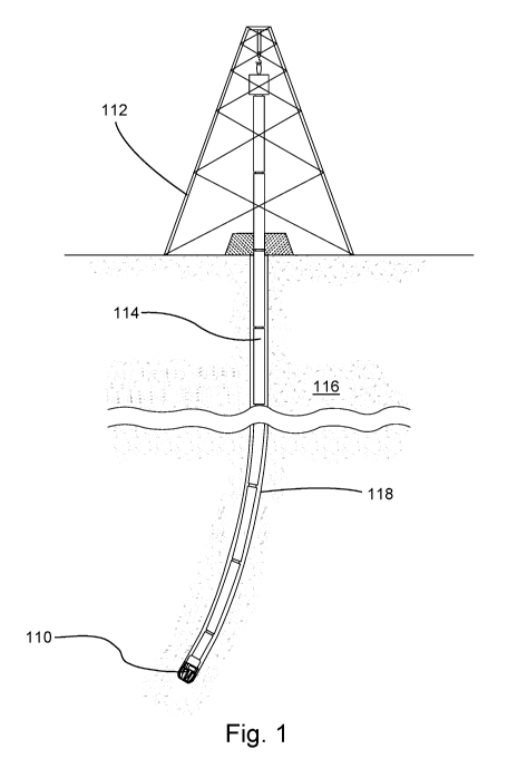
In Figure 1, an embodiment of a drill bit 110 is shown suspended from a
derrick 112 by a
drill string 114. While a land-based derrick is shown, water-based structures
are also common.
Such a drill string may be formed from a plurality of drill pipe sections
fastened together end-to-
end or, in other embodiments, a flexible tubing may be used. As the drill bit
110 is rotated,
either from the derrick 112 or by a downhole motor, it may engage and degrade
a subterranean
formation 116 to form a borehole 118 therethrough. Drilling fluid may be
passed along the drill
string 114 and expelled at the drill bit 110 to cool and lubricate the drill
bit 110 as well as carry
loose debris to a surface of the borehole 118 through an annulus surrounding
the drill string 114.
At times it may be desirable to take measurements or perform various functions
within a
borehole while drilling is in progress. It is believed that certain
measurements and functions are
most effective when taken or performed as close as possible to an end of a
drill string, or on a
drill bit itself However, such drill bits often experience significant wear
and damage while
drilling, due to the harsh conditions experienced during drilling. Worn or
damaged drill bits
often require replacement which can be expensive and time consuming.
Instrumenting drill bits
to take measurements or perform functions may significantly add to replacement
expense and
complexity.
2
CA 03095123 2020-09-24
WO 2019/191013
PCT/US2019/023954
One of the more complex aspects of instrumenting such a drill bit is providing
a
mechanism for communicating back and forth across the connection between the
drill bit and the
drill string. Such connections are typically made by threading a drill bit to
a drill string amid an
often dirty and hectic drilling operation. Given the disorder of such
conditions it may be difficult
to certify the final positions, either rotationally or axially, of the drill
bit relative to the drill
string. Any communication mechanism spanning such a connection must be robust
and
functional regardless of orientation.
Another feature adding complexity to drill bit instrumentation is the
externally-threaded
protrusions and the internally-threaded cavities that commonly form either
side of the
.. connection. In particular, passing communications into a cavity may be
difficult as access may
be restricted by space constraints. Thus, a mechanism capable of passing
communications across
a drill-string-to-drill-bit connection independent of specific rotational
orientation while providing
access inside a threaded cavity may prove useful in instrumenting a drill bit.
BRIEF DESCRIPTION
One technique for controlling a direction of travel of a drill bit as it forms
a borehole
through the earth may be to give the borehole a cross-sectional shape that
urges the drill bit
laterally. Much energy may be saved in this manner as the borehole does the
urging, rather than
a drilling tool. A borehole capable of urging a drill bit laterally may have a
cross-sectional shape
comprising two circular arcs, one with a larger radius and one with a smaller
radius than that of a
.. drilling tool passing through the borehole. The drilling tool may be pushed
away from the
smaller circular arc and into the open space provided by the larger circular
arc. This lateral
pushing may add a curve to the borehole as it is formed having a center of
curvature closer to the
larger circular arc than the smaller circular arc.
These two circular arcs, while centered at a common axis of the borehole, may
each
.. occupy a distinct angular range about this axis. A sharpness of the curve
imparted to the
borehole as it is formed may depend on the relative radii and angular sizes of
the two circular
arcs. Thus, the drill bit may be precisely steered by changing these relative
radii and angular
sizes and the rotational orientations of the two circular arcs at different
positions along the length
of the borehole.
3
CA 03095123 2020-09-24
WO 2019/191013
PCT/US2019/023954
Producing these two circular arcs may be accomplished by first rotating a
drilling tool to
bore a hole through the earth and then extending a cutting element from a side
of the drilling tool
during only a portion of its rotation. While extended, this cutting element
may remove
additional earthen material from an internal surface of the borehole to form a
first of the circular
.. arcs. While retracted, a second circular arc may be formed. Adjusting the
relative radii, angular
sizes and rotational orientations of these two circular arcs as the borehole
is formed, to steer the
drilling tool, may be achieved by altering the timing of the extension and
retraction.
A steerable downhole tool may alter a direction of travel of a drill bit while
drilling into
the earth by extending a rod from openings disposed in a side of the tool. The
rod may slide
within a cavity, spanning a width of the tool, passing from one of the
openings to another and
extending from various openings at various times.
The rod may degrade material from an internal surface of a borehole in which
the drill bit
is traveling, by engaging the surface with cutter elements exposed on opposing
tips of the rod. A
stabilizer, protruding from the side of the tool, may then push off of the
borehole wall opposite
.. from the area of degradation to drive the drill bit into the degraded
region.
For example, while the tool is rotating within the borehole, the rod may be
extended from
a first of the openings. With the rod extended, the tool may be rotated about
an axis thereof to
degrade a portion of the borehole. After a certain amount of rotation, roughly
one-half of a full
rotation in some embodiments, the rod may be retracted to a neutral position
within the tool. The
.. tool may continue to rotate until a second of the openings is adjacent to
the area where the rod
was initially extended. At this point, the rod may be extended from the second
opening and the
tool may be rotated another roughly one-half rotation to continue degradation
of the same area.
In another embodiment, a drill bit may be rotated to form a borehole through
the earth.
Such a drill bit may comprise fixed cutting elements, capable of degrading
subterranean
.. materials, protruding from an exterior of a body. These fixed cutting
elements may be spaced at
a constant radius from a rotational axis of the body to form an initially
cylindrical borehole.
The body may also comprise at least one rotatable cutting element protruding
from its
exterior. To remove earthen material from an internal wall of the borehole,
the rotatable cutting
element may be positioned in a first rotational orientation wherein it may
extend radially beyond
.. the constant radius of the fixed cutting elements. To stop removing
material from the borehole
4
CA 03095123 2020-09-24
WO 2019/191013
PCT/US2019/023954
wall, the rotatable cutting element may be positioned in a second rotational
orientation wherein it
may remain radially within the constant radius.
Rotation of the rotatable cutting element may be synchronized with rotation of
the drill
bit to provide consistent removal in certain angular sections of the borehole.
By altering material
removal in these angular sections various borehole cross-sectional shapes may
be formed.
Specifically, a borehole may be provided with a smaller internal radius at
some angular positions
that may urge the drill bit laterally into other angular positions comprising
a larger internal radius
to steer the drill bit.
In another embodiment, an apparatus may comprise an axial body, such as that
of a drill
bit or stabilizer. One or more extendable cutting elements may be extendable
in a single radial
direction from an exterior of the body as the body rotates within a borehole.
Extension of the
cutting elements may allow them to engage and degrade an inner wall of the
borehole. By
timing these extensions various cross-sectional shapes may be created.
An abrasion-resistant gauge pad, protruding from the exterior of the body, may
ride
against the borehole wall without rapidly wearing the gauge pad or
significantly damaging the
borehole. Riding against the borehole wall provided with the cross-sectional
shape described
earlier may urge the body radially.
A piston's stroke length may be defined by a rod passing through a through
hole in the
piston, restricting the piston's motion, and altered by adjusting the rod. In
some embodiments,
this rod may comprise a noncylindrical external geometry that may interact
with an interior of
the piston's through hole. A radius of this noncylindrical external geometry
may vary along an
axial length of the rod or around a circumference thereof Adjustment of the
rod, via axial
translation or rotation for example, may change a point of contact between the
rod's external
geometry and the through hole's interior and adjust possible stroke lengths.
Alternately, the
through hole may comprise a unique geometry in which the rod may radially
translate to adjust
the piston's stroke length.
A drill bit assembly may comprise a chassis, separate from a drill bit, housed
within a
cavity of the drill bit. A drill string may be secured to the drill bit and
retain the chassis within
the cavity. The chassis may comprise two pairs of interfacing exchange
surfaces, a first pair
disposed between the chassis and the drill string and a second pair disposed
between the chassis
and the drill bit. Both of the first pair of interfacing exchange surfaces are
annular in shape and
5
CA 03095123 2020-09-24
WO 2019/191013
PCT/US2019/023954
fixed together independent of rotational orientation. The second pair of
interfacing exchange
surfaces are fixed together in a specific rotational orientation. These pairs
of interfacing
exchange surfaces may allow for various types of signals, such as electrical,
hydraulic, optical or
electromagnetic for example, to be exchanged and passed through the chassis or
to electronics
disposed on the chassis. These electronics may be disposed on an exterior of
the chassis and
contained within at least one pressure chamber formed between the exterior of
the chassis and an
interior of the drill bit. In such a configuration, instrumentation may be
removed from one drill
bit and inserted into another, and thus reused, when one drill bit becomes
worn or damaged.
A downhole drilling assembly may comprise a sub secured between a drill string
and a
drill bit. This sub may comprise a cavity formed therein and a chassis may be
housed within the
cavity. The drill bit may also comprise a cavity formed therein and an
extender may be housed
within this cavity. This extender may contact the drill bit at a base of this
cavity and extend to
within two inches of a mouth of the cavity. This extender may provide access
for various types
of communication to reach into the drill bit's cavity.
Several pairs of interfacing exchange surfaces may allow for communication
(e.g.
passing electrical, hydraulic, optical or electromagnetic signals) between
these various elements.
One pair of interfacing exchange surfaces, between the drill string and the
chassis, may allow for
communication regardless of relative rotational orientation. Two other pairs
of interfacing
exchange surfaces, one between the chassis and the extender and another
between the extender
and the drill bit, may require a specific rotational orientation for
communication.
The first pair of interfacing exchange surfaces may allow for communication
regardless
of rotational orientation. Meanwhile, the extender may allow for access within
the cavity of the
drill bit. The combination may allow for measurements to be taken or functions
to be performed
on the drill bit.
DRAWINGS
Figure 1 is an orthogonal view of an embodiment of a subterranean drilling
operation.
Figure 2 is a perspective view of an embodiment of a drill bit attached to an
end of a drill
string.
Figures 3-1 through 3-4 are cross-sectional views of embodiments of drilling
tools
disposed within non-circular subterranean boreholes.
6
CA 03095123 2020-09-24
WO 2019/191013
PCT/US2019/023954
Figures 4-1 through 4-4 are cross-sectional views of additional embodiments of
drilling
tools disposed within non-circular subterranean boreholes.
Figure 5 is an orthogonal view of an embodiment of a non-circular subterranean
borehole.
Figures 6 and 7 are perspective and longitude-sectional views, respectively,
of
embodiments of steerable downhole drill bits.
Figure 8 is a longitude-sectional view of an embodiment of a steerable
downhole drill
pipe section comprising an interchangeable stabilizer.
Figure 9 is a cross-sectional view of an embodiment of a steerable downhole
tool
comprising a locking mechanism.
Figures 9-1 and 9-2 are orthogonal views of embodiments of slidable rods of
various
geometries.
Figures 10-1 through 10-4 are orthogonal views of embodiments of drill bits in
boreholes,
each representing one step of a method for steering a downhole tool.
Figure 11 is a sectional view of an embodiment of a piston slidably disposed
within a
hollow cylinder and a rod passing through a through hole in the piston,
restricting a stroke
thereof
Figures 12-1 and 12-2 are sectional views of embodiments of pistons comprising
adjustable rods passing therethrough capable of altering stroke restrictions
of each piston.
Figure 12-3 is a perspective view of an embodiment of a rod of the type shown
in Figures 12-1
and 12-2.
Figures 13-1 and 13-2 are sectional views of additional embodiments of pistons
comprising adjustable rods passing therethrough. Figure 13-3 is a perspective
view of an
embodiment of a rod of the type shown in Figures 13-1 and 13-2.
Figure 14 is an orthogonal view of another embodiment of a piston and rod
combination.
Figure 15 is a perspective view of an embodiment of a drill bit that may form
part of a
subterranean drilling operation.
Figures 16-1 and 16-2 are orthogonal views of embodiments of a drill bit
comprising a
rotatable cutting element, shown in magnified view, in different rotational
orientations.
Figures 17-1 and 17-2 are orthogonal views of embodiments of rotatable cutting
elements
in different rotational orientations.
7
CA 03095123 2020-09-24
WO 2019/191013
PCT/US2019/023954
Figures 18-1 and 18-2 are perspective views of embodiments of a drill bit
comprising a
rotatable cutting element rotatable by means of a torque-generating apparatus
comprising a rack
and pinion gear configuration.
Figures 19-1 and 19-2 are perspective views of embodiments of a rotatable
cutting
element rotatable by means of a torque-generating apparatus comprising a worm
gear
configuration.
Figures 20-1 and 20-2 are perspective views of embodiments of a rotatable
cutting
element rotatable by means of a torque-generating apparatus, capable of
contacting an external
formation, and limited by a braking apparatus.
Figure 21 is an orthogonal view of an embodiment of multiple rotatable cutting
elements
all rotatable by means of a single torque-generating apparatus.
Figure 22 is a perspective view of an embodiment of a drill bit that may form
part of a
subterranean drilling operation.
Figure 23 is a longitude-sectional view of another embodiment of a drill bit.
Figure 24-1 is a perspective view of an embodiment of a piston comprising a
plate of
superhard material. Figure 24-2 is a perspective view of an embodiment of a
piston comprising a
plurality of cutting elements.
Figure 25-1 and 25-3 are perspective views of embodiments of drill bits
comprising
cutting elements extendable via rotation of a hinged arm. Figure 25-2 is a
perspective view of an
embodiment of a hinged arm.
Figure 26-1 and 26-3 are perspective views of embodiments of drill bits
comprising
cutting elements extendable via rotation of a cylindrical drum. Figure 26-2 is
a perspective view
of an embodiment of a cylindrical drum.
Figure 27 is a longitude-sectional view of an embodiment of a drill bit
comprising an
extendable push pad positioned opposite from extendable cutting elements.
Figures 28-1 through 28-3 are perspective views of embodiments of gauge pads.
Figures 28-4 and 28-5 are perspective views of embodiments of abrasion-
resistant devices.
Figure 29 is a perspective view of another embodiment of a drill bit.
Figure 30 is a perspective view of an embodiment of a stabilizer.
Figure 31 is a perspective view of an embodiment of drill bit assembly.
Figure 32 is a perspective view of an embodiment of a disassembled drill bit
assembly.
8
CA 03095123 2020-09-24
WO 2019/191013
PCT/US2019/023954
Figure 32-1 is a perspective view of an embodiment of an interchangeable
plate.
Figure 33 is a longitude-sectional view of an embodiment of drill bit
assembly.
Figures 34-1 and 34-2 are perspective views of embodiments of chassis.
Figure 35 is a longitude-sectional view of an embodiment of a downhole
drilling
assembly that may form part of a subterranean drilling operation.
Figures 36-1 and 36-2 are perspective views of additional embodiments of
downhole
drilling assemblies.
Figure 37 is a perspective view of an embodiment of a rotationally-independent
pair of
interfacing exchange surfaces.
Figure 38 is a perspective view of an embodiment of a rotationally-specific
pair of
interfacing exchange surfaces.
DETAILED DESCRIPTION
Referring now to the figures, Figure 2 shows an embodiment of a drill bit 210
secured to
an end of a drill string 214 that may form part of a subterranean drilling
operation of the type just
described. A plurality of blades 220 may protrude from the drill bit 210,
spaced around a
rotational axis thereof. Each of the blades 220 may comprise a plurality of
fixed cutters 221
secured thereto capable of degrading earthen materials. As the drill bit 210
rotates, these
cutters 221 may form a long hollow borehole through the earth. Such a borehole
may comprise
an initial radius determined by spacing between the fixed cutters 221 and a
rotational axis of the
drill bit 210.
At least one cutting element 222, also capable of degrading the earth, may be
extendable
from a side of the drill bit 210 (or another downhole tool in alternate
embodiments). This
extendable cutting element 222 may scrape earthen material away from an
internal wall of a
borehole initially formed by the fixed cutters 221. When extended, the
extendable cutting
element 222 may enlarge the radius of the borehole, from its initial size, in
certain areas.
Figure 3-1 shows an embodiment of a drill bit 310-1 disposed within an
elongate hollow
borehole 318-1 formed in the earth 316-1. The borehole 318-1 may comprise a
central
axis 335-1 passing therethrough and a cross-sectional shape formed within a
plane perpendicular
to the axis 335-1. A plurality of fixed cutters 321-1, capable of degrading
the earth 316-1, may
be disposed on the drill bit 310-1. These fixed cutters 321-1 may be spaced
about the axis 335-1
9
CA 03095123 2020-09-24
WO 2019/191013
PCT/US2019/023954
to form an initially cylindrical borehole with a constant radius as the drill
bit 310-1 is rotated.
An extendable cutting element 322-1 may be extended from a side of the drill
bit 310-1 to
expand this initial borehole radius by removing additional earthen material
from an internal wall
of the borehole 318-1. This extendable cutting element 322-1 may be extended
for only a
fraction of a full rotation of the drill bit 310-1, before being retracted,
such that this larger
borehole radius is only present in an angular range of the borehole 318-1.
Through this
technique the borehole 318-1 may acquire a cross-sectional shape comprising
two different
circular arcs, each with a uniquely sized radius. In particular, a first
circular arc 330-1, centered
at the axis 335-1, may comprise a first radius 331-1, while a second circular
arc 332-1, centered
at the same axis 335-1, may comprise a second radius 333-1, smaller than the
first radius 331-1.
Figure 3-2 shows an embodiment of drilling tool 310-2 disposed within a non-
circular
borehole 318-2, similar to that shown in Figure 3-1. The drilling tool 310-2
may comprise a
cross section with a radius 334-2 that is smaller than the first radius 331-1,
shown in Figure 3-1,
that was formed by extension of the extendable cutting element 322-1. This
drilling tool 310-2
cross-sectional radius 334-2 may also be larger than the second radius 333-1
of Figure 3-1 that
was formed by the fixed cutters 321-1 of the drill bit 310-1. The drilling
tool 310-2, in fact, may
not fit through a borehole formed exclusively by the fixed cutters 321-1
without the enlargement
created by the extendable cutting element 322-1. This sizing mismatch may
constantly, and with
little energy exerted by the drilling tool 310-2, urge the drilling tool 310-2
laterally (as indicated
by arrow 340-2) as the smaller second radius 333-1 pushes the drilling tool
310-2 into space
created by the larger first radius 331-1.
Also due to this size discrepancy, the drilling tool 310-2 may contact an
internal wall of
the borehole 318-2 generally at two points 336-2 and 337-2 of the cross
section shown. These
two points 336-2, 337-2 may be located on the smaller second radius 333-1.
Limiting contact
generally to two points may reduce friction between the drilling tool 310-2
and the
borehole 318-2.
Figure 3-3 shows an embodiment of a drilling tool 310-3 disposed within a non-
circular
borehole 318-3. In this embodiment, a first angular range 338-3 occupied by a
first circular
arc 330-3, forming part of a cross-sectional shape of the borehole 318-3, is
larger than a second
angular range 339-3 occupied by a second circular arc 332-3. The relative
dimensions of these
first and second angular ranges 338-3, 339-3 may be determined and adjusted by
altering the
CA 03095123 2020-09-24
WO 2019/191013
PCT/US2019/023954
timing of extension and retraction of an extendable cutting element as
described in relation to
Figure 3-1.
Figure 3-4 shows another embodiment of a drilling tool 310-4 disposed within a
non-circular borehole 318-4. In this embodiment, first and second angular
ranges 338-4, 339-4,
occupied by first and second circular arcs 330-4, 332-4, are even more
divergent in relative size
than those shown in previous embodiments. As the second angular range 339-4
decreases in size
relative to the first angular range 338-4, a lateral urging (as indicated by
arrow 340-4) of the
borehole 318-4 against the drilling tool 310-4 may decrease as well. Thus, a
rate of steering of a
drill bit as it forms a borehole through the earth may be controlled by
altering timing of
extension and retraction of extendable cutting elements.
Figures 4-1 and 4-2 show an embodiment of a single subterranean borehole 418-1
at
different positions along its length. At a first position along a length of
the borehole 418-1,
shown in Figure 4-1, a cross section of the borehole 418-1 may comprise a
first circular
arc 430-1 positioned at a first rotational orientation. In this orientation, a
drilling tool 410-1
disposed within the borehole 418-1 may be urged (as indicated by arrow 435-1)
toward the first
circular arc 430-1. At a second position along the borehole 418-1 length,
shown in Figure 4-2, a
rotational orientation of a first circular arc 430-2 may be rotated relative
to the first circular
arc 430-1 shown in Figure 4-1 (as indicated by arrow 450-2). This
reorientation of the first
circular arc 430-2 may cause the borehole 418-1 to urge the drilling tool 410-
1 in a different
direction (as indicated by arrow 435-2). Thus, by adjusting the rotational
orientation of a
borehole's circular arcs, a drilling tool may be urged in various azimuthal
directions.
Figures 4-3 and 4-4 show an embodiment of a single subterranean borehole 418-3
at
different positions along its length. At a first position along a length of
the borehole 418-3,
shown in Figure 4-3, a cross section may comprise a first circular arc 430-3
comprising a first
.. radius 440-3. A drilling tool 410-3 disposed within the borehole 418-3 may
be urged (as
indicated by arrow 435-3) toward the first circular arc 430-3. At a second
position along the
borehole 418-3 length, shown in Figure 4-4, a radius 440-4 of a first circular
arc 430-4 may be
enlarged relative to the radius 440-3 of the first circular arc 430-3 shown in
Figure 4-3. This
resizing of the radius 440-4 may steer the borehole 418-3 in a tighter radius
of curvature.
Figure 5 shows an embodiment of a section of elongate hollow borehole 518
formed in
an earthen formation. This borehole 518 may have an axis 544 passing
therethrough and a cross-
11
CA 03095123 2020-09-24
WO 2019/191013
PCT/US2019/023954
sectional shape comprising first and second circular arcs 530, 532 of distinct
radii centered at the
axis 544. These first and second circular arcs 530, 532 may be adjusted
relative to each other in
both radii, angular size and rotational orientation during drilling such that
they differ at various
points along a length of the borehole 518. By adjusting these first and second
circular arcs 530,
532 as drilling progresses, the borehole 518 may be formed to comprise
multiple curves along its
axis 544. These various curves may comprise unique radii of curvature based on
the relative
dimensions of the first and second circular arcs 530, 532 and the lateral
urging forces created
thereby. For example, a first curve 540 of the borehole 518, curving toward
the first circular
arc 530, may comprise a first radius of curvature 541. The size of this first
radius of
curvature 541 may depend on the relative radii and angular sizes of the first
and second circular
arcs 530, 532. If this first radius of curvature 541 is not changing a
direction of the borehole 518
as rapidly as desirable, then the relative dimensions of the first and second
circular arcs 530, 532
may be altered, thus resulting in an increased urging force. For instance, in
a second curve 542
of the borehole 518, an angular size of the first circular arc 530 may be
reduced while an angular
size of the second circular arc 532 may be expanded. By so doing, a second
radius of
curvature 543 within the second curve 542 may be smaller than the first radius
of curvature 541
leading to a more rapid change of direction.
Figure 6 shows one embodiment of a drill bit 612 capable of degrading the
earth, when
rotated, to form a borehole therethrough. The drill bit 612 may be joined at
an attachment
end 620 thereof to a drill string (not shown) running the length of such a
borehole. Opposite
from the attachment end 620 the drill bit 612 may comprise an engagement end
621 comprising a
plurality of blades 622 protruding therefrom. These blades 622 may be
generally spaced about a
periphery of the engagement end 621 and wrap from the engagement end 621 over
to a side 623
of the drill bit 612. A plurality of tough cutter elements 626 may be secured
to each of the
blades 622 to aid in degrading hard earthen materials.
The side 623 may span from the attachment end 620 to the opposing engagement
end 621
and comprise an opening 624 therein. A tip 625, comprising additional cutter
elements 627
secured thereto, may be extendable from within the opening 624 to degrade a
specific section of
an adjacent borehole wall (not shown) surrounding the drill bit 612. A
stabilizer 628, axially
spaced from the opening 624, may protrude from the side 623. This stabilizer
628 may comprise
tough gauge elements 629 designed to push against and ride along the borehole
wall without
12
CA 03095123 2020-09-24
WO 2019/191013
PCT/US2019/023954
wearing away. As the cutter elements 627 of the tip 625 degrade the specific
wall section, as
described previously, the stabilizer 628 may push off of the borehole wall
into the degraded
section, as will be described below.
Figure 7 shows another embodiment of a drill bit 712. The drill bit 712
comprises a
plurality of threads 737 disposed within an attachment end 720 thereof,
providing a mechanism
for attachment to a drill string (not shown). The drill bit 712 also comprises
a conduit 738
passing therethrough, allowing for drilling fluid conducted along a drill
string to exit from an
engagement end 721 of the drill bit 712, through nozzles 739 disposed therein,
to aid in drilling.
A first opening 724 on a side 723 of the drill bit 712 may be connected to a
second
opening 734, opposite the first opening 724, by an elongate cavity 730 passing
through the drill
bit 712. Cutter elements 725, 726, extendable from the first opening 724 and
second
opening 734 respectively, may be attached to a common rod 731 slidable within
the cavity 730.
As the rod 731 slides within the cavity 730 the cutter elements 725, 726 may
extend or retract
from their respective openings. Because both cutter elements 725, 726 are
secured to opposing
tips of the same rod 731, as one extends the other may retract. In the
embodiment shown, the
rod 731 is positioned between the engagement end 721 of the drill bit 712 and
a plenum 740 of
the conduit 738 wherein the nozzles 739 separate therefrom.
Extension or retraction of the cutter elements 725, 726 may be caused by the
introduction
of pressurized fluid that may urge the rod 731 to slide within the cavity 730.
In the embodiment
shown, pressurized fluid within a first channel 732 may urge the rod 731 to
extend from the first
opening 724. Subsequently, pressurized fluid within a second channel 733 may
urge the rod 731
to return to a neutral position within the cavity 730. In some embodiments,
such as the one
shown, at least one spring 735 may also urge the rod 731 toward the neutral
position.
Pressurized fluid within the second channel 733 may then urge the rod 731 to
extend from the
second opening 734.
One motivation for securing the cutter elements 725, 726 to the single rod 731
may be to
maintain a generally consistent borehole width while drilling. Further, it is
believed that the
specific positioning of the cutter elements 725, 726 relative to a remainder
of the drill bit 712
may be important to maintaining a consistent borehole width. In the embodiment
shown, cutter
elements 725, 726 disposed on opposing tips of the rod 731 are positioned
farther apart from
each other than opposing stabilizers 728 protruding from the side 723 of the
drill bit 712. The
13
CA 03095123 2020-09-24
WO 2019/191013
PCT/US2019/023954
stabilizers 728 themselves may be positioned farther apart than a width of the
engagement
end 721 of the drill bit 712 such that the cutter elements 725, 726 are not
required to degrade too
much material. In such a configuration, the cutter elements 725, 726 may
remain exposed at all
times, to some degree, to an adjacent borehole wall (not shown) surrounding
the drill bit 712.
Figure 8 shows an embodiment of another steerable downhole tool, a drill pipe
section in
this case. The drill pipe section comprises a main body 812 rotatable about an
axis 841 and
comprising a first end 820 opposite from a second end 821. Both the first and
second
ends 820, 821 may comprise threads for connection to other elements. A side
823 may span
between the first and second ends 820, 821. This side 823 may comprise two
openings 824, 834
therein both leading to a cavity 830 passing through the body 812. A rod 831
may be slidably
disposed within the cavity 830. Both the rod 831 and cavity 830 may be
positioned within a
plane perpendicular to the rotational axis 841. In the embodiment shown, the
rod 831 actually
intersects the rotational axis 841 of the body 812, however this is not
necessary.
The rod 831 may comprise a shaft 842 surrounded by a bearing sleeve 843. The
rod 831
may also comprise replaceable caps 844, 845 secured on opposing tips of the
shaft 842. In the
embodiment shown the replaceable caps 844, 845 are held to the shaft 842 via a
threaded bolt;
however a variety of other connections are also possible. The caps 844, 845
may be replaceable
to allow for quick exchange should they become worn out or damaged.
A stabilizer body 846 may be threadably secured to the first end 820 of the
main
body 812. This stabilizer body 846 may have a stabilizer 828 protruding
radially therefrom.
When the stabilizer body 846 is threaded to the main body 812 the stabilizer
828 may sit axially
spaced from the opening 824 of the main body 812. In this position, the
stabilizer 828 may push
against a borehole wall (not shown) when the rod 831 is extended from the
opposite
opening 834. In this thread-on configuration, the stabilizer body 846 may be
interchangeable
with other similar bodies to allow for quick modification of stabilizer size,
or merely
replacement when worn or damaged.
Figure 9 shows another embodiment of a steerable downhole tool comprising a
rod 931
and cavity 930 offset from a rotational axis 941 of a body 912 of the tool. In
this embodiment,
the tool also comprises a locking mechanism 950 housed within the body 912.
While a variety
of designs are possible, the locking mechanism 950 shown comprises a latch 951
that may
translate relative to the rod 931. When translated toward the rod 931, a
convergent point of the
14
CA 03095123 2020-09-24
WO 2019/191013
PCT/US2019/023954
latch 951 may engage with a mating geometry of the rod 931 to first urge the
rod 931 toward a
neutral position within the cavity 930 and then eventually lock the rod 931 in
place within the
cavity 930. When translated away from the rod 931, the latch 951 may release
the rod 931 such
that it may again slide freely within the cavity 930. It has been found that
forming the latch 951
and rod 931 of different materials, each comprising unique properties, may
reduce galling during
locking allowing for ease of release.
Translation of the latch 951 may be achieved by adjusting fluid pressures in
various
chambers surrounding the latch 951. These chambers may be filled by the same
pressurized
fluid used to urge the rod 931 to extend or retract. For example, in the
embodiment shown, a
first chamber 952 may be pressurized at a generally constant pressure. When no
other forces are
acting, this generally constant pressure may urge the latch 951 against the
rod 931 to lock it in
place. When either of a second chamber 953 or third chamber 954 are filled
with pressurized
fluid however, the generally constant pressure within the first chamber 952
may be overcome to
urge the latch 951 away from the rod 931 and release it from lock. Pressurized
fluid being
channeled to urge the rod 931 to slide axially in one direction may also feed
into the second
chamber 953 while pressurized fluid being channeled to urge the rod 931 to
slide axially in an
opposite direction may feed into the third chamber 954. Thus, in such a
configuration, the
rod 931 may be axially locked until fluid is sent to urge it in either
direction, and then it may be
unlocked and free to slide.
Figures 9-1 and 9-2 show embodiments of rods 931-1, 931-2 comprising various
cross-
sectional geometries. The cross-sectional geometries of the rods 931-1, 931-2
may be non-
cylindrical and may mate with matching cavities to restrain rotation of the
rods 931-1, 931-2
relative to their respective cavities. This restraint may keep cutter elements
925-1, 925-2,
attached to each of the rods 931-1, 931-2, aligned as their respective tools
rotate.
Figures 10-1 through 10-4 show different steps to downhole steering made
possible by
aspects of the embodiments described previously. Specifically, Figure 10-1
shows an initial
position of a steering tool 1012-1 comprising a slidable rod 1031-1 housed
therein. In this
figure, the rod 1031-1 is positioned in a neutral position within the tool
1012-1. As a tool 1012-2
rotates, as shown in Figure 10-2, about a central axis thereof, a rod 1031-2
may be slid in one
direction along its length such that it extends from one side of the tool 1012-
2. Extension of this
rod 1031 2 may cause a first cutter element 1025-2 attached to the rod 1031-2
to engage and
CA 03095123 2020-09-24
WO 2019/191013
PCT/US2019/023954
degrade a borehole wall 1011-2 surrounding the tool 1012-2. This extension may
also push a
stabilizer 1028-2, positioned opposite from the first cutter element 1025-2,
against the borehole
wall 1011-2, thus pushing the entire tool 1012-2 in the direction of the
degradation.
After rotating about its axis generally 180 degrees (other amounts are also
anticipated),
as shown in Figure 10-3, a rod 1031-3 may retract to the neutral position
within its respective
tool 1012-3. From this position, a second cutter element 1026-4, as shown in
Figure 10-4,
attached to a rod 1031-4, opposite from a first cutter element 1025-4, may be
extended from a
side of a tool 1012-4 to degrade a borehole wall 1011-4 while the tool 1012-4
rotates another
generally 180 degrees in a similar manner as shown previously; with a
different stabilizer 1028-4
pushing toward the area of degradation. From here, the method may repeat from
the beginning.
Figure 11 shows an embodiment of piston 1110 slidably disposed within a hollow
cylinder 1111 formed in a mass 1112. An arrow shows a direction 1113 of
possible travel for
this piston 1110 that may be aligned with a central axis 1117 of the piston
1110. The
piston 1110 and cylinder 1111 may combine to form a volume 1114 capable of
containing a
fluid. A gasket 1115 may surround the piston 1110 and keep fluid contained
within the
volume 1114 from escaping between the piston 1110 and cylinder 1111. An
increase in fluid
pressure within the volume 1114 may urge the piston 1110 to slide out of the
cylinder 1111.
Conversely, a decrease in fluid pressure may pull the piston 1110 back into
the cylinder 1111.
The piston 1110 may comprise a through hole 1116 passing therethrough. In the
embodiment shown, the through hole 1116 passes radially across the piston
1110, perpendicular
to and touching the central axis 1117 of the piston 1110; although other
arrangements are also
possible.
A rod 1118 may span the hollow cylinder 1111 from one side to another; secured
to
internal walls of the cylinder 1111 at opposing ends thereof This rod 1118 may
also be
positioned perpendicular to the central axis 1117 of the piston 1110,
similarly to the through
hole 1116, and extend through the through hole 1116. By extending through the
through
hole 1116 and attaching to opposing sides of the cylinder 1111, the rod 1118
may restrict axial
motion of the piston 1110.
Internal dimensions of the through hole 1116 may be larger than external
dimensions of
the rod 1118, allowing the piston 1110 to translate a certain distance before
restriction by the
rod 1118. A distance that the piston 1110 may travel before contacting the rod
1118 may define
16
CA 03095123 2020-09-24
WO 2019/191013
PCT/US2019/023954
a stroke length 1119 for the piston 1110. Further, a cross section of the
through hole 1116 may
comprise a generally oblong shape that is elongated in the direction 1113 of
travel of the
piston 1110.
A solenoid 1120, or other type of control device in alternate embodiments, may
adjust a
position of this rod 1118 and this adjustment may alter the defined stroke
length 1119. Such
adjustments may provide additional benefits such as distributing impact wear
between the
rod 1118 and the through hole 1116. This solenoid 1120 may comprise at least
one electrically
conductive wire 1121 wound in a coil. If an electrical current is passed
through such a wire 1121
a magnetic field may be produced that may act on certain materials forming the
rod 1118.
Examples of other types of control devices capable of adjusting a position of
a rod, that may
replace the solenoid in other embodiments, include a hydraulic pump and ball
screw. It is
believed that such alternate control devices may provide additional accuracy
at an expense of
additional complexity.
Figures 12-1 and 12-2 show embodiments of adjustable rods 1218-1, 1218-2 that
may
alter respective stroke lengths 1219-1, 1219-2 of associated pistons 1210-1,
1210-2. These
alterations may be enabled by unique geometries possessed by the rods 1218-1,
1218-2.
Specifically, such rods 1218-1, 1218-2 may each comprise a noncylindrical
external geometry
that may encounter an interior of a through hole 1216-1, 1216-2 of its
associated
piston 1210-1, 1210-2 at different points based on the rods' 1218-1, 1218-2
positioning.
Figure 12-3 shows an embodiment of a rod 1218-3 comprising a noncylindrical
external
geometry characterized by a radius 1222-3, spaced from a central axis 1223-3
of the rod 1218-3,
that varies in magnitude along an axial length of the rod 1218-3. While a wide
variety of radial
variations are anticipated, for simplicity's sake, this embodiment comprises
two substantially
constant radial sections; a first section 1224-3 comprising a relatively
smaller radius and a
second section 1225-3 comprising a relatively larger radius. The present
embodiment also
comprises a generally sloping transition between these two substantially
constant radial sections.
In Figure 12-1, a linear solenoid 1220-1 retains the associated rod 1218-1 in
a relatively
retracted position such that only a first section 1224-1 thereof, comprising a
relatively smaller
radius, may extend into the through hole 1216-1 of the piston 1210-1. Because
only the
relatively smaller first section 1224-1 may contact the interior of the
through hole 1216-1, the
17
CA 03095123 2020-09-24
WO 2019/191013
PCT/US2019/023954
piston 1210-1 may have a relatively longer potential stroke length 1219-1
before being restricted
by contact with the rod 1218-1.
In Figure 12-2, a linear solenoid 1220-2 ejects the associated rod 1218-2
axially to a
relatively extended position such that a second section 1225-2 thereof,
comprising a relatively
larger radius, may also extend into the through hole 1216-1 of the piston 1210-
1, in addition to a
first, relatively smaller, section 1224-2. With this relatively larger second
section 1225-2 also
potentially contacting the interior of the through hole 1216-2, the piston
1210-2 may have a
relatively shorter potential stroke length 1219-2 due to changed location of
contact with the
rod 1218-2.
Figures 13-1 and 13-2 show embodiments of other adjustable rods 1318-1, 1318-2
that
may alter stroke lengths 1319-1, 1319-2 of associated pistons 1310-1, 1310-2
by a different
mechanism. Such stroke length alterations may still be enabled by rods 1318-1,
1318-2
comprising noncylindrical external geometries. However, in these embodiments,
external
geometries of the rods 1318-1, 1318-2 may vary around a circumference thereof.
For example, Figure 13-3 shows an embodiment of a rod 1318-3 comprising a
radius 1322-3, spaced from a central axis 1323-3 of the rod 1318-3, that
varies in magnitude
around a circumference of the rod 1318-3. While a wide variety or radial
variations are possible,
again for simplicity's sake, the embodiment comprises a flat surface 1330-3
running parallel to
the central axis 1323-3 of the rod 1318-3 and perpendicular to a radius of the
rod 1318-3.
In Figure 13-1, a rotary solenoid 1320-1 positions the associated rod 1318-1
rotationally
such that a flat surface 1330-1 thereof faces a direction 1313-1 of travel of
the piston 1310-1. As
this flat surface 1330-1 creates a shorter distance from a central axis 1323-1
of the rod 1318-1 to
an external geometry thereof, compared to other portions of the rod 1318-1,
the piston 1310-1
may have a relatively longer potential stroke length 1319-1 with the rod 1318-
1 in this rotational
position.
In Figure 13-2, a rotary solenoid 1320-2 may rotate the associated rod 1318-2
such that a
flat surface 1330-2 thereof faces at generally right angles to a direction
1313-2 of travel of the
piston 1310-2. In this position, the stroke length 1319-2 may shorten in that
the rod 1318-2 may
restrain translation of the piston 1310-2 sooner. While only two positions are
shown, generally
at right angles from each other about a central axis of a rod, any of a
variety of angular positions
18
CA 03095123 2020-09-24
WO 2019/191013
PCT/US2019/023954
between these two extremes may provide a partially restricting effect allowing
for variable
control of a stroke length.
The through holes of the embodiments discussed thus far have comprised
generally
oblong cross-sectional shapes. Other shapes are also anticipated, however. For
example,
Figure 14 shows an embodiment of a piston 1410 with a through hole 1416
passing therethrough.
This through hole 1416 may comprise a cross-sectional shape featuring a
generally triangular
section 1440 and a notch 1441 section. A rod 1418 passing through the through
hole 1416 may
restrict translation of the piston 1410 when in contact with an interior of
the through hole 1416.
In the embodiment shown, this rod 1418 is capable of radial translation, or
translation
perpendicular to a central axis 1417 of the piston 1410. Adjustment of the rod
1418 in this
manner may reposition it with respect to the through hole 1416. Specifically,
radial translation
of the rod 1418 within the generally triangular section 1440 of the through
hole 1416 may
change an internal width 1442, extending in a direction parallel with the
central axis 1417 of the
piston 1410, at the location of the rod 1418. Changing this through hole 1416
width 1442 may
grant the piston 1410 a different stroke length.
Additionally, the notch 1441 section of the through hole 1416 may comprise an
internal
width 1443 substantially similar to an external dimension of the rod 1418 in
the same direction.
If the rod 1418 is translated into the notch 1441 section, the stroke length
1419 of the
piston 1410 may be restricted to naught effectively locking the position of
the piston 1410 in
place.
Figure 15 shows an embodiment of a drill bit 1510 of the type that may form
part of a
subterranean drilling operation. The drill bit 1510 may comprise a generally
cylindrical
body 1520 that may be rotated about a central axis 1521 thereof On one end,
the body 1520
may comprise an attachment mechanism 1522, shown here as a series of threads.
This
attachment mechanism may secure the drill bit 1510 to a mating attachment
device disposed on a
distal end of a drill string (not shown). Opposite from the attachment
mechanism 1522, the
body 1520 may comprise a plurality of blades 1523 extending both radially and
longitudinally
therefrom, spaced around the axis 1521 of the body 1520.
Each of these blades 1523 may comprise a leading edge with a plurality of
fixed cutting
elements 1524 protruding therefrom. Each of these fixed cutting elements 1524
may comprise a
portion of superhard material (i.e. material comprising a Vickers hardness
test number
19
CA 03095123 2020-09-24
WO 2019/191013
PCT/US2019/023954
exceeding 40 gigapascals) secured to a substrate. The substrate may be formed
of a material
capable of firm attachment to the body 1520. As the drill bit 1510 is rotated,
the superhard
material of each fixed cutting element 1524 may engage and degrade tough
earthen matter. Each
of the fixed cutting elements 1524 may be spaced at a constant radius relative
to the axis 1521 of
the body 1520 to create an initially cylindrical borehole.
In addition to the fixed cutting elements 1524, a rotatable cutting element
1525 may also
protrude from an exterior of the body 1520. This rotatable cutting element
1525 may also
comprise a portion of superhard material secured to a substrate, similar in
some respects to the
fixed cutting elements 1524. An exposed surface of the rotatable cutting
element 1525 may
comprise a three-dimensional geometry incorporating some of this superhard
material. Based on
its rotational orientation, this exposed geometry may engage an internal wall
of the borehole and
remove earthen matter therefrom. Removing this material may change an internal
radius of the
borehole in some areas. The amount of earthen matter removed may be altered by
rotation of the
rotatable cutting element 1525 relative to the body 1520.
Figure 16-1 shows an embodiment of a drill bit 1610-1 rotatable about an axis
1621-1.
The drill bit 1610-1 comprises a plurality of fixed cutting elements 1624-1
exposed on leading
edges of a plurality of blades 1623-1. At least one of the fixed cutting
elements 1624-1,
positioned farthest from the axis 1621-1 of any of the plurality, may form a
gauge cutting
element 1634-1. A distance from the axis 1621-1 to this gauge cutting element
1634-1 may
define an initial radius 1630-1 of a borehole as the drill bit 1610-1 is
rotated.
A rotatable cutting element 1625-1 may also protrude from an exterior surface
of the drill
bit 1610-1 in relative proximity to the gauge cutting element 1634-1. In
contrast to the fixed
cutting elements 1624-1, this rotatable cutting element 1625-1 may be capable
of rotation,
relative to the drill bit 1610-1, about its own axis 1631-1. An exposed
portion of this rotatable
cutting element 1625-1 may comprise a three-dimensional geometry comprising an
offset distal
end 1632-1. This exposed geometry may also comprise a slanting surface 1633-1
that may
stretch from the offset distal end 1632-1 toward a proximal base thereof
The unique aspects of this three-dimensional exposed geometry may allow it to
extend
radially beyond the initial radius 1630-1 in a first rotational orientation as
shown. In this first
rotational orientation, the slanting surface 1633-1 may be positioned in a
generally parallel
alignment with a leading face of the gauge cutting element 1634-1. It is
believed that such an
CA 03095123 2020-09-24
WO 2019/191013
PCT/US2019/023954
alignment may, in some subterranean formations, lead to a smoother extension
of the offset distal
end 1632-1. Also, in this first rotational orientation, the slanting surface
1633-1 may be
positioned in a generally normal alignment relative to the initial radius 1630-
1.
When extended in this manner, the offset distal end 1632-1 may cut an extended
radius 1635-1 into the borehole by removing additional earthen matter from an
internal wall of
the borehole. Removing material from this internal wall may change an internal
radius of the
borehole, at least in an angular section thereof This extended radius 1635-1
may be restricted to
certain angular sections positioned about a circumference of the borehole via
deliberate
rotational control of the rotatable cutting element 1625-1 to create
purposefully non-cylindrical
cross-sectional shapes.
Figure 16-2 shows another embodiment of a drill bit 1610-2, similar in many
regards to
that shown in Figure 16-1. In this embodiment, however, a rotatable cutting
element 1625-2
protruding from an exterior surface of the drill bit 1610-2 may be rotated
into a second rotational
orientation. In this second rotational orientation, an exposed three-
dimensional geometry of the
rotatable cutting element 1625-2 may remain within an initial radius 1630-2
defined by an
outermost fixed gauge cutting element 1634-2. Specifically, in this second
rotational orientation,
a slanting surface 1633-2 of the exposed geometry may be positioned in a
generally tangent
alignment relative to the initial radius 1630-2 such that it may smoothly
avoid an internal wall of
a borehole without removing material therefrom.
If extension and retraction of the rotatable cutting element 1625-2 is
performed in unison
with rotation of the drill bit 1610-2, such that a given rotational
orientation of the drill bit 1610-2
correlates with a set rotational orientation of the rotatable cutting element
1625-2, then a
consistent borehole cross-sectional shape may be created. Various embodiments
of such unison
rotation may comprise spinning the rotatable cutting element 1625-2 in
consecutive full turns or
oscillating it back and forth. In addition, or alternatively, extension and
retraction of the
rotatable cutting element 1625-2 may be performed at higher frequencies to
reduce likelihood of
the drill bit 1610-2 sticking to the borehole wall.
Figures 17-1 and 17-2 show embodiments of a rotatable cutting element 1725-1,
1725-2
protruding from an exterior surface of a drill bit 1710-1, 1710-2 in relative
proximity to a fixed
gauge cutting element 1734-1, 1734-2, also protruding from the exterior
surface. In contrast to
the gauge cutting element 1734-1, 1734-2, this rotatable cutting element 1725-
1, 1725-2 may be
21
CA 03095123 2020-09-24
WO 2019/191013
PCT/US2019/023954
capable of rotation, relative to the drill bit 1710-1, 1710-2, about its own
axis 1731-1, 1731-2.
An exposed portion of this rotatable cutting element 1725-1, 1725-2 may
comprise a generally
flat distal surface 1733-1, 1733-2.
In a first rotational orientation of the rotatable cutting element 1725-1, as
shown in
Figure 17-1, the exposed portion may extend radially beyond an initial radius
1730-1 defined by
a position of the gauge cutting element 1734-1. In a second rotational
orientation, as shown in
Figure 17-2, the rotatable cutting element 1725-2 may be rotated around its
axis 1731-2 such that
the exposed portion may remain within an initial radius 1730-2.
Figures 18-1 and 18-2 show embodiments of a drill bit 1810-1, 1810-2
comprising a
rotatable cutting element 1825-1, 1825-2 protruding from an exterior surface
thereof. The
rotatable cutting element 1825-1, 1825-2 may be actively rotated by a torque-
generating
apparatus 1850-1, 1850-2. Such a torque-generating apparatus may be powered by
any of a
variety of known transducers capable of converting electrical, hydraulic or
other types of energy
into linear or rotary motion; such as a solenoid, piston, turbine or the like.
Based on the type of
transducer chosen, the torque-generating apparatus may be capable of external
control,
continuous full rotation, rotational oscillation, holding a set position, etc.
This torque-generating apparatus 1850-1, 1850-2 may be connected to the
rotatable
cutting element 1825-1, 1825-2 via a set of gears. In the embodiment shown,
the torque-
generating apparatus 1850-1, 1850-2 comprises an axially-translatable rack
gear 1851-1, 1851-2.
Teeth of this rack gear 1851-1, 1851-2 may mesh with those of a pinion gear
1852-1, 1852-2
attached to the rotatable cutting element 1825-1, 1825-2. Thus, as the rack
gear 1851-1, 1851-2
translates, the pinion gear 1852-1, 1852-2 may rotate the rotatable cutting
element 1825-1,
1825-2. Specifically, as shown in Figure 18-1, as the torque-generating
apparatus 1850-1
translates 1853-1 the rack gear 1851-1 outward along its axis, the pinion gear
1852-1
rotates 1854-1 the rotatable cutting element 1825-1 into an extended position,
radially past a
fixed gauge cutting element 1834-1. As shown in Figure 18-2, as the torque-
generating
apparatus 1850-2 translates 1853-2 the rack gear 1851-2 inward, the pinion
gear 1852-2
rotates 1854-2 the rotatable cutting element 1825-2 into a retracted position,
radially within a
fixed gauge cutting element 1834-2. Such an arrangement could be reversed in
alternate
embodiments.
22
CA 03095123 2020-09-24
WO 2019/191013
PCT/US2019/023954
Figures 19-1 and 19-2 show embodiments of a rotatable cutting element 1925-1,
1925-2
that may be rotated by a torque-generating apparatus 1940-1, 1940-2. In these
embodiments, the
torque-generating apparatus 1940-1, 1940-2 is connected to the rotatable
cutting
element 1925-1, 1925-2 via a worm-wheel gear configuration. In particular, the
torque-
generating apparatus 1940-1, 1940-2 may comprises a rotatable worm gear 1941-
1, 1941-2.
Teeth of this worm gear 1941-1, 1941-2 may mesh with those of a worm wheel
gear 1942-1, 1942-2 attached to the rotatable cutting element 1925-1, 1925-2.
Thus, as the worm
gear 1941-1, 1941-2 rotates, the worm wheel gear 1942-1, 1942-2 may also
rotate the rotatable
cutting element 1925-1, 1925-2. Specifically, as shown in Figure 19-1, as the
torque-generating
apparatus 1940-1 rotates 1943-1 the worm gear 1941-1 in a first direction, the
worm wheel
gear 1942-1 rotates 1944-1 the rotatable cutting element 1925-1 into an
extended position. As
shown in Figure 19-2, as the torque-generating apparatus 1940-2 rotates 1943-2
the worm
gear 1941-2 in a second direction, the worm wheel gear 1942-2 rotates 1944-2
the rotatable
cutting element 1925-2 into a retracted position. Such an arrangement could be
reversed in
alternate embodiments.
Figures 20-1 and 20-2 show embodiments of a rotatable cutting element 2025-1,
2025-2
that may be rotated by a torque-generating apparatus 2040-1, 2040-2. In these
embodiments, the
torque-generating apparatus 2040-1, 2040-2 wraps around a circumference of the
rotatable
cutting element 2025-1, 2025-2 and comprises a geometry capable of protruding
from a drill bit
and engaging with an external formation through which the drill bit may be
advancing. While
thus engaged, rotation of the drill bit or its advancement through a formation
may cause this
torque-generating apparatus 2040-1, 2040-2 to rotate the rotatable cutting
element 2025-1, 2025-1.
The rotatable cutting element 2025-1, shown in Figure 20-1, may be freely
rotatable 2044-1 about an axis thereof In Figure 20-2, however, a braking
apparatus 2070-2
may engage a cam 2071-2 portion of the rotatable cutting element 2025-2. While
engaged, this
braking apparatus 2070-2 may rotationally secure the rotatable cutting element
2025-1 and
restrain 2044-2 it from free rotation.
Figure 21 shows an embodiment of multiple rotatable cutting elements 2125-1,
2125-2
and 2125-3 that all may be rotated by a single torque-generating apparatus
2140. Similar in
some respects to the torque-generating apparatus shown in Figures 19-1 and 19-
2, this torque
23
CA 03095123 2020-09-24
WO 2019/191013
PCT/US2019/023954
generating apparatus 2140 may comprise a worm gear 2141 with teeth wrapping
therearound. In
this embodiment however, each of the multiple rotatable cutting elements 2125-
1, 2125-2
and 2125-3 may comprise a unique worm wheel gear 2142-1, 2142-2 and 2142-3,
respectively,
connected thereto. Teeth of each of these worm wheel gears 2142-1, 2142-2 and
2142-3 may
mesh with those of the worm gear 2141 such that as the torque-generating
apparatus 2140 rotates
the worm gear 2141 each of the rotatable cutting elements 2125-1, 2125-2 and
2125-3 may rotate
simultaneously. As can be seen, each of these rotatable cutting elements 2125-
1, 2125-2
and 2125-3 may extend away from the torque-generating apparatus 2140, and
protrude from an
exterior of a drill bit 2110, in different radially-angular directions without
interfering with one
another. While a worm-wheel gear system is shown, alternate embodiments may
comprise other
arrangements comprising multiple rotatable cutting elements connected to a
single torque-
generating apparatus.
Figure 22 shows an embodiment of a drill bit 2210 that may form part of a
subterranean
drilling operation. Although any of a variety of drill bit types may be
functional with the novel
elements described herein (e.g. roller cone bits, diamond impregnated bits and
hybrids thereof),
the embodiment of the drill bit 2210 shown comprises a plurality of blades
2220 protruding from
one end thereof spaced around a rotational axis 2221 thereof In the embodiment
shown the
plurality of blades 2220 are generally aligned with the rotational axis 2221,
however in other
embodiments blades may spiral around a circumference of a drill bit. A
plurality of cutting
elements 2222, capable of degrading tough earthen matter, may be disposed on
each of the
blades 2220. If this drill bit 2210 is rotated within an earthen formation,
these cutting
elements 2222 would normally create a generally cylindrically shaped borehole
with a constant
radius. The drill bit 2210 may also comprise a threadable attachment 2223,
comprising a series
of threads disposed within a cavity (hidden), disposed on an opposite end from
the plurality of
blades 2220.
Additional cutting elements 2224 may be extendable in a generally radial
direction from
an exterior of the drill bit 2210. Extension of these cutting elements 2224
may cause them to
engage a wall of a borehole (not shown) through which the drill bit 2210 may
be traveling and
scrape earthen material away from the borehole wall at certain points around
its circumference.
This scraping may cause the shape of the borehole to deviate away from the
generally cylindrical
shape initially created by the rigidly-secured cutting elements 2222 of the
drill bit 2210. For
24
CA 03095123 2020-09-24
WO 2019/191013
PCT/US2019/023954
example, if the cutting elements 2224 are extended during only a portion of a
full rotation of the
drill bit 2210, then the borehole may be given a new cross-sectional shape
comprising two
distinct radii, an initial radius formed by the secured cutting elements 2222
and an enlarged
radius formed by the extendable cutting elements 2224.
While any of a variety of cutting element types may be used for extension, the
present
embodiment depicts a rotatable type of cutting element similar in some
respects to those shown
in U.S. Patent No. 7,703,559 to Shen et al.
In the embodiment shown, these extendable cutting elements 2224 are secured to
an
exposed end of a piston 2226 that may be extended or retracted by hydraulic
pressure. While
only a single piston is shown in the present embodiment, in various other
embodiments a
plurality of extendable cutting elements, each secured to its own unique
piston, similar in some
respects to those shown in Figure 2A of U.S. Patent No. 8,763,726 to Johnson
et al., is also
possible.
An abrasion-resistant gauge pad 2228 may protrude from the exterior of the
drill bit 2210
and be positioned axially adjacent the extendable cutting elements 2224. In
the embodiment
shown only one abrasion-resistant gauge pad 2228 is shown aligned with the
single radial
direction, however in other embodiments a plurality of abrasion-resistant
gauge pads may be
positioned at a variety of locations about a circumference of a body. For
example, in some
embodiments each of a plurality of blades may comprise its own gauge pad. At
this gauge
pad 2228 the drill bit 2210 may comprise a cross-sectional radius sized
between the two borehole
radii discussed previously; larger than the smaller radius formed by the rigid
cutting
elements 2222 but smaller than the larger radius formed by the extendable
cutting
elements 2224. In fact, this gauge pad 2228 radius may not fit through a
borehole formed
exclusively by the rigid cutting elements 2222 without the enlargement created
by the extendable
cutting elements 2224. This sizing mismatch may constantly, and with little
energy exerted by
the drill bit 2210, urge the drill bit 2210 laterally as the smaller radius
pushes the drill bit 2210
into space created by the larger radius.
To achieve its abrasion resistance, preventing wear caused by rubbing against
the
borehole wall, the gauge pad 2228 may comprise one or more studs 2229 embedded
therein.
These studs 2229 may be formed of superhard materials (i.e. materials
comprising a Vickers
hardness test number exceeding 40 gigapascals). Generally cylindrical studs
are shown in the
CA 03095123 2020-09-24
WO 2019/191013
PCT/US2019/023954
present embodiment, however studs of a variety of shapes and sizes, and
arranged in a variety of
patterns, are also contemplated.
Axially adjacent the extendable cutting elements 2224 and gauge pad 2228 a
second
cutting element 2225 and third cutting element 2227 may be rigidly secured to
the exterior of the
drill bit 2210. The second cutting element 2225 may sit axially adjacent the
extendable cutting
elements 2224 opposite from the gauge pad 2228 while the third cutting element
2227 may sit
axially adjacent the gauge pad 2228 opposite from the extendable cutting
elements 2224. In the
embodiment shown, these second and third cutting elements 2225, 2227 are shown
aligned with
the single radial direction, however in other embodiments similar cutting
elements may be
positioned at a variety of locations about a circumference of a body. The
third cutting
element 2227 may effectively ream out the borehole deviation created by the
extendable cutting
elements 2224, or to a larger diameter, leaving the borehole generally
cylindrical once again.
While the present embodiment shows a solitary third cutting element 2227, in
other
embodiments a plurality of cutting elements may perform such a reaming
function.
Figure 23 shows another embodiment of a drill bit 2310 comprising extendable
cutting
elements 2324, an abrasion-resistant gauge pad 2328, and second and third
cutting
elements 2325, 2327. The gauge pad 2328 is seen to slant away from a
rotational axis 2321 of
the drill bit 2310. It is believed that this slanting of the gauge pad 2328
may aid in allowing a
borehole wall to urge the drill bit 2310 sideways while avoiding rapid wear
due to rubbing. As is
also visible from this angle, while a distance from the rotational axis 2321
to the extendable
cutting elements 2324 is variable, similar distances to the gauge pad 2328 and
second and third
cutting elements 2325, 2327 may be fixed. In this fixed arrangement, the gauge
pad 2328 may
protrude farther from the rotational axis 2321 of the drill bit 2310 than the
second cutting
element 2325 and the third cutting element 2327 may protrude farther than the
gauge pad 2328.
The extendable cutting elements 2324 may be extended or retracted based on
hydraulic
pressure acting on a base of a piston 2326 secured to the cutting elements
2324. Pressurized
hydraulic fluid may be channeled against the base of the piston 2326 via a
conduit 2330 passing
through the drill bit 2310 built for this purpose. In various configurations,
this hydraulic fluid
may be regulated to control a physical position of the piston 2326 or a force
applied to the
piston 2326. In the embodiment shown, a pin 2331 may be secured to the drill
bit 2310 and pass
through a passageway intersecting the piston 2326 similar in some respects to
those shown in
26
CA 03095123 2020-09-24
WO 2019/191013
PCT/US2019/023954
U.S. Patent No. 9,085,941 to Hall etal. This pin 2331 may regulate the limits
of extension and
retraction of the cutting elements 2324.
A seal 2332 may surround a perimeter of the piston 2326 to block the
pressurized
hydraulic fluid from escaping out between the piston 2326 and drill bit 2310
and into the
borehole. In the embodiment shown, this seal 2332 takes the form of two
elastomeric rings
disposed within grooves encircling the piston 2326 at around a midpoint of its
axial length. In
other embodiments, however, a similar seal may be positioned at any point
axially along a piston
from an exposed portion to a base thereof. Additionally, other seal
embodiments may comprise
a flexible material like a thin metallic bellows that may, in some
circumstances, provide more
wear resistance than an elastomer. In some embodiments a close fit may suffice
to retain fluid
without such a seal.
Figure 24-1 shows an embodiment of a piston 2426-1 that may be radially
extendable
from a drill bit (not shown) or other axial body. Rather than comprising
separate cutting
elements secured thereto, as shown in embodiments of pistons discussed
previously, an entire
exposed portion 2440-1 of the piston 2426-1 may be covered by a plate of
superhard material to
form a single extendable cutting element. The piston 2426-1 may be free to
rotate about a
central axis thereof to distribute wear about a circumference of the exposed
portion 2440-1. In
the embodiment shown, the exposed portion 2440-1 of the piston 2426-1
comprises a generally
flat principal surface. Alternate embodiments, however, may have any of a
variety of non-flat
profiles.
Figure 24-2 shows another embodiment of a piston 2426-2 comprising two cutting
elements secured to an exposed end thereof A first cutting element 2424-2
secured to the
piston 2426-2 may protrude from the exposed end a first distance and may dig
into a borehole
wall 2442-2 a certain amount. A second cutting element 2444-2 may protrude
farther than the
first cutting element 2424-2 but dig into the borehole wall 2442-2
substantially the same amount
as the first cutting element 2424-2. This is possible if the second cutting
element 2444-2 is
spaced farther from a distal end of an axial body (not shown) than the first
cutting
element 2424-2 and the first cutting element 2424-2 removes matter from the
borehole
wall 2442-2 as it digs. In this configuration, reaction forces experienced by
the first and second
cutting elements 2424-2, 2444-2 may balance rotational torque around an axis
of the
piston 2441-2.
27
CA 03095123 2020-09-24
WO 2019/191013
PCT/US2019/023954
Figure 25-1 shows an embodiment of a drill bit 2510-1 comprising one or more
cutting
elements 2524-1 radially extendable and retractable from an exterior thereof.
In the embodiment
shown, the cutting elements 2524-1 are in an extended configuration exposing
them to external
impact. These cutting elements 2524-1 may be secured to a hinged arm 2550-1.
Figure 25-2
shows an embodiment of such a hinged arm 2550-2 comprising several cutting
elements 2524-2
attached thereto and a pin 2551-2 extending from a body thereof. The pin 2551-
2 may attach the
hinged arm 2550-2 to a drill bit (not shown) such that the hinged arm 2550-2
is rotatable about a
rotational axis 2552-2 passing through the pin 2551-2.
Figure 25-3 shows another embodiment of a drill bit 2510-3 comprising a hinged
arm 2550-3 with cutting elements 2524-3 secured thereto. In this embodiment,
the hinged
arm 2550-3 is rotated to retract the cutting elements 2524-3 from an exterior
of the drill
bit 2510-3. In this retracted configuration the cutting elements 2524-3 may be
shielded from
impact. Thus, when extended, as shown in Figure 25-1, the cutting elements
2524-1 may engage
a borehole wall (not shown) surrounding the drill bit 2510-1. Alternatively,
while retracted, as
shown in Figure 25-3, the cutting elements 2524-3 may be shielded from
engaging the borehole
wall.
In these embodiments, the rotational axis, about which a hinged arm may
rotate, runs
generally parallel to a rotational axis of a drill bit. However, other
configurations similar in
some respects to those shown in U.S. Patent No. 8,141,657 to Hutton are also
possible.
Figures 26-1 and 26-3 show additional embodiments of drill bits 2610-1 and
2610-3 each
comprising one or more cutting elements 2624-1 and 2624-3 radially extendable
and retractable
from exteriors thereof These cutting elements 2624-1 and 2624-3 may be secured
to rotatable
cylindrical drums 2660-1 and 2660-3. Figure 26-2 shows an embodiment of such a
cylindrical
drum 2660-2 comprising cutting elements 2624-2 secured thereto and rotatable
about a rotational
axis 2662-2. When rotated to an extended configuration, as shown in Figure 26-
1, the cutting
elements 2624-1 may engage a borehole wall (not shown) surrounding the drill
bit 2610-1.
While rotated to a retracted configuration, as shown in Figure 26-3, the
cutting elements 2624-3
may be shielded from engaging the borehole wall. In these embodiments, the
rotational axis,
about which the cylindrical drum may rotate, runs generally parallel to a
tangent of the drill bit to
which the cylindrical drum is attached.
28
CA 03095123 2020-09-24
WO 2019/191013
PCT/US2019/023954
Figure 27 shows another embodiment of a drill bit 2710. In addition to cutting
elements 2724 extendable in a single radial direction (similar in many
respects to embodiments
previously described), the drill bit 2710 of the present embodiment further
comprises a push
pad 2770 extendable from the exterior opposite from the single radial
direction. Such a push
pad 2770 may push off a borehole wall (not shown) surrounding the drill bit
2710 to push the
drill bit 2710 toward the cutting elements 2724. This pushing may stabilize
the drill bit 2710 as
the cutting elements 2724 engage the borehole wall. This pushing may also urge
the drill
bit 2710 into the now degraded borehole wall to aid in directing the drill bit
2710 as it
progresses.
In the embodiment shown, both the push pad 2770 and the cutting elements 2724
are
connected to sources of pressurized hydraulic fluid that may impel them
outward. In some
embodiments, this may even be the same source. In such cases, if a conduit
2737 channeling
pressurized hydraulic fluid to the push pad 2770 is activated simultaneously
with a conduit 2730
channeling pressurized hydraulic fluid to the extendable cutting elements 2724
then both may
extend at the same time.
To avoid damaging a borehole wall, and disturbing its cross-sectional shape,
various
elements may be added to the gauge pads previously described. For example, the
gauge
pad 2228 shown in Figure 22 comprises a plurality of studs 2229 formed of
superhard materials
embedded therein. These studs 2229 may allow the gauge pad 2228 to smoothly
push off a
.. borehole wall. In other embodiments, such as one shown in Figure 28-1, a
gauge pad 2828-1
may comprise a plate 2829-1 of superhard material secured thereto and covering
an exposed
section thereof It is believed that such a plate may enhance the smooth
borehole push off.
In an embodiment shown in Figure 28-2, an abrasion-resistant device 2829-2 may
be
attached to a gauge pad 2828-2 such that it may freely rotate about an axis
2882-2. When acted
upon by an external force, such as from a borehole wall, this abrasion-
resistant device 2829-2
may rotate out of the way rather than resist. It is believed that this lack of
resistance may protect
both the borehole wall and the gauge pad 2828-2. Figure 28-4 shows an
embodiment of an
abrasion-resistant device 2829-4, similar to that shown in Figure 28-2,
comprising a plate 2880-4
of superhard material secured to a shaft 2881-4. This shaft 2881-4 may be
attached to a gauge
.. pad allowing the plate 2880-4 to rotate thereabout.
29
CA 03095123 2020-09-24
WO 2019/191013
PCT/US2019/023954
Figure 28-3 shows another embodiment of an abrasion-resistant device 2829-3
rotatably
attached to a gauge pad 2828-3 and Figure 28-5 shows an embodiment of a
similar
abrasion-resistant device 2829-5. Rather than comprising a plate of superhard
material, the
abrasion-resistant device 2829-5 may comprise a plate 2880-5 formed of hard
material with a
plurality of studs 2889-5, formed of superhard material, embedded therein.
While Figures 28-2
and 28-3 show embodiments of abrasion-resistant devices 2829-2, 2829-3
connected to gauge
pads 2828-2, 2828-3 at only one end of a rotatable axis projecting generally
outward from the
gauge pad 2828-2, 2828-3, other embodiments of abrasion-resistant devices may
comprise
rotational axes in various alternate orientations and possibly connected to a
gauge pad at multiple
ends.
Figure 29 shows an embodiment of a drill bit 2910 comprising a unique gauge
pad 2928.
This gauge pad 2928 comprises an abrasion-resistant device 2929 formed
generally in the shape
of a ring 2990 with a plurality of studs 2929, formed of superhard materials,
embedded in an
exterior surface thereof In the embodiment shown, this ring 2990 generally
surrounds a
circumference of the drill bit 2910. However, other sizes and configurations
are also possible.
When acted upon by an external force the ring 2990 may rotate around an axis
thereof rather
than resist.
Figure 30 shows an embodiment of a stabilizer 3010 that may form part of a
subterranean
drilling operation. The stabilizer 3010 may comprise a plurality of blades
3020 protruding
therefrom spaced around a rotational axis 3021 thereof A plurality of cutting
elements 3022,
capable of degrading tough earthen matter, may be disposed on each of the
blades 3020. The
stabilizer 3010 also comprises threadable attachments 3023, 3123 disposed on
opposite ends
thereof Additional cutting elements 3024 may be extendable in a single radial
direction from an
exterior of the stabilizer 3010. Extension of these cutting elements 3024 may
cause them to
engage a wall of a borehole (not shown) through which the stabilizer 3010 is
traveling. This
engagement may degrade the borehole wall at certain points around its
circumference causing a
cross-sectional shape of the borehole to deviate away from circular.
Additionally, an abrasion-
resistant gauge pad 3028 may protrude from the exterior of the stabilizer 3010
and be positioned
axially adjacent the extendable cutting elements 3024.
Figure 31 shows an embodiment of a downhole drill bit assembly comprising a
drill
bit 3112 secured to an end of a drill string 3114. The drill bit 3112 may
comprise a plurality of
CA 03095123 2020-09-24
WO 2019/191013
PCT/US2019/023954
blades 3122 protruding therefrom. These blades 3122 may be generally spaced
about a
periphery of one end of the drill bit 3112, opposite from the drill string
3114, and comprise a
plurality of tough cutter elements 3126 attached to each of the blades 3122 to
aid in degrading
hard earthen materials. While a fixed-bladed type drill bit is shown, a
variety of other drill bit
types could alternately be used.
Figure 32 shows an embodiment of a downhole drill bit assembly that has been
partially
disassembled to highlight several features thereof For example, a drill string
3214 may
comprise a protrusion 3230 extending from one end thereof. This protrusion
3230 may be
inserted into a cavity 3231 of a drill bit 3212. In the embodiment shown, the
protrusion 3230
comprises a plurality of threads 3232 disposed thereabout that may engage with
comparable
threads 3233 formed on an internal surface of the cavity 3231 to secure the
protrusion 3230
within the cavity 3231. These threads 3232 and 3233 may comprise complementary
geometries
such that they cease relative rotation once the protrusion 3230 arrives at a
fixed position relative
to the cavity 3231. Various markings 3240 and 3241 exposed on exterior
surfaces of the drill
string 3214 and drill bit 3212, respectively, may also indicate relative
alignment.
The protrusion 3230 may comprise an interfacing exchange surface 3234 disposed
on a
distal tip thereof Various embodiments of interfacing exchange surfaces may
allow for the
exchange of electrical, hydraulic, optical and/or electromagnetic signals. In
the embodiment
shown, the interfacing exchange surface 3234 is capable of exchanging power
and data, via
electricity and hydraulic fluid, with another interfacing exchange surface
3258 housed within the
cavity 3231. Specifically, the interfacing exchange surface 3234 comprises an
inductive
ring 3235 that may sit adjacent another inductive ring 3236 of the other
interfacing exchange
surface 3258. While adjacent, electrical signals passing through the one
inductive ring 3235 may
be communicated to the other inductive ring 3236. These electrical signals may
be passed
regardless of rotational orientation of the drill string 3214 relative to the
drill bit 3212.
As also shown in this embodiment, the interfacing exchange surface 3234
comprises two
ducts 3237 exposed on the protrusion 3230 that may conduct fluid into the
cavity 3231 and to
two other ducts 3238 exposed on the other interfacing exchange surface 3258.
These sets of two
ducts 3237 and 3238 may allow for hydraulic power to be transmitted from the
drill string 3214
to the drill bit 3212. Two nearly-semiannular grooves 3239 may also be
positioned on the
interfacing exchange surface 3234, one adjacent each of the two ducts 3237
exposed thereon.
31
CA 03095123 2020-09-24
WO 2019/191013
PCT/US2019/023954
These nearly-semiannular grooves 3239 may allow fluid to flow therethrough
from the two
ducts 3237 of the protrusion 3230 to the two ducts 3238 of the cavity 3231 in
a wide span of
rotational orientations of the drill string 3214 relative to the drill bit
3212. Further, in the event
that the span of possible rotational orientations is insufficient, a plate
3259, as shown removed
from the interfacing exchange surface 3234 in Figure 32-1, forming the nearly-
semiannular
grooves 3239 could be exchanged with one comprising offset grooves to adjust
the relative
positions. As can be seen, only one of a pair of interfacing exchange surfaces
needs such
grooves for this type of rotationally independent fluid transfer.
Figure 33 shows another embodiment of a downhole drill bit assembly. As can be
seen, a
chassis 3342, comprising a body separate from a drill bit 3312, may be
disposed within a
cavity 3331 of the drill bit 3312. A drill string 3314 may be threaded into
the cavity 3331 and
retain the chassis 3342 therein. If the drill string 3314 were to be
unthreaded, the chassis 3342
could be removed from the cavity 3331 and inserted into a different drill bit.
This may be
advantageous if the drill bit 3312 becomes worn or damaged. Both the drill
string 3314 and the
chassis 3342 may comprise a fluid channel 3349 passing therethrough allowing
drilling fluid
traveling through the drill string 3314 to exit through at least one nozzle
3348 of the drill
bit 3312.
The drill string 3314 may connect to the chassis 3342 via a pair of
interfacing exchange
surfaces 3334, similar to those described previously. In this embodiment, the
interfacing
exchange surfaces 3334 allow for exchange of electricity and hydraulic fluids.
For example, a
pair of inductive rings 3335 may allow for exchanging electrical signals
between the drill
string 3314 and the chassis 3342. These electrical signals may be passed to
electronics 3343
disposed on an exterior surface of the chassis 3342. These electronics 3343
may be housed
within a pressure chamber 3344 formed between the chassis 3342, the cavity
3331 of the drill
bit 3312, and pressure seals 3345 disposed on either side of the electronics
3343.
The electronics 3343 may receive additional electrical signals from a sensor
3346,
capable of sensing characteristics of a surrounding borehole or parameters of
an associated
drilling operation, positioned on an exterior surface of the drill bit 3312.
It is believed that
positioning certain types of sensors as close as possible to an end of a drill
bit may be
advantageous.
32
CA 03095123 2020-09-24
WO 2019/191013
PCT/US2019/023954
In another example, a fluid duct 3337 may allow fluid to flow from the drill
string 3314
into another duct 3338 within the chassis 3342. This flow may be possible
regardless of
rotational positioning of the drill string 3314 relative to the chassis 3342.
This other duct 3338
may pass completely through the chassis 3342 and conduct fluid to a cavity
3347 within the drill
bit 3312. As the cavity 3347 is filled, a piston 3350 may be forced by fluid
pressure within the
cavity 3347 to extend from an exterior of the drill bit 3312.
In the embodiment shown, electrical and hydraulic interfacing exchange
surfaces 3357
between the chassis 3342 and the drill bit 3312 may be fixed together in a
specific rotational
orientation such that they rotate together. As can be seen, one of these
interfacing exchange
surfaces 3357 may connect through the chassis 3342 to one of the other
interfacing exchange
surfaces 3334 described previously. Additionally, in the case of the
electrical connection, the
electronics 3343 may be connected to one or both of the interfacing exchange
surfaces 3334, 3357.
Figures 34-1 and 34-2 show embodiments of chassis 3442-1, 3442-2. These
chassis 3442-1, 3442-2 may be generally tubular shaped with a fluid channel
3449-1, 3449-2
passing therethrough. These chassis 3449-1, 3449-2 may also comprise various
electronics 3443-1, 3443-2 disposed circumferentially about an exterior
surface thereof. An
interfacing exchange surface may be disposed on either end of the chassis 3442-
1, 3442-2.
Specifically, a first interfacing exchange surface 3451-1, 3451-2, providing
for a connection
independent of rotational orientation, may be disposed on one end of the
respective
chassis 3442-1, 3442-2 and a second interfacing exchange surface 3450-1, 3450-
2, providing for
a connection of specific rotational orientation, may be disposed on an
opposite end thereof. The
first interfacing exchange surface 3451-1 may comprise ducts 3452-1 for
hydraulic exchange and
an inductive ring 3453-1 for electrical exchange. The second interfacing
exchange
surface 3450-2 may comprise ducts 3452-2 for hydraulic exchange and a stab
connection 3453-2
for electrical exchange.
Figure 35 shows an embodiment of a downhole drilling assembly 3511 comprising
a drill
string 3514 secured to a sub 3520, and the sub 3520 further secured to a drill
bit 3510. A
continuous fluid channel 3525 may pass axially through the drill string 3514
and sub 3520, and
into the drill bit 3510. While any of a variety of types of drill bits may
serve in this role and
function with the novel elements described herein, the present embodiment
drill bit 3510
33
CA 03095123 2020-09-24
WO 2019/191013
PCT/US2019/023954
comprises a plurality of blades 3521, spaced around a central axis, protruding
from one end
thereof A plurality of cutting elements 3522 may be exposed on leading edges
of each of the
blades 3521. Such cutting elements 3522 may comprise a superhard material
(i.e. a material
comprising a Vickers hardness test number exceeding 40 gigapascals) capable of
degrading
tough subterranean materials. When the drill bit 3510 is rotated about this
axis, the blades 3521
may engage an earthen formation allowing the cutting elements 3522 to bore a
hole therein.
While it is common for drill bits used in downhole drilling to comprise a
threaded
protrusion extending therefrom for attachment, the drill bit 3510 of the
embodiment shown
comprises an internally-threaded cavity 3523 positioned axially opposite the
blades 3521 and
cutting elements 3522. An extender 3524 may be seated within this cavity 3523.
This may
allow for access deep into the drill bit 3510. When seated, this extender 3524
may comprise a
proximal end that contacts a nadir of the drill bit 3510 cavity 3523. The
cavity 3523 may be
formed so deep into the drill bit 3510 that the cutting elements 3522 axially
span this proximal
end and nadir. The extender 3524 may also comprise and a distal end that
extends to within two
inches of a mouth of the cavity 3523. It is believed that this positioning
relative to the
cavity's 3523 mouth may allow for relatively easy access to this distal end.
In the embodiment
shown, the extender 3524 comprises a generally conical exterior shape. This
conical shape may
be widest toward the proximal end and narrow as it approaches the distal end.
Additionally, the
fluid channel 3525 may pass axially through the extender 3524.
The sub 3520 may be secured to the drill bit 3510 via an externally threaded
protrusion 3526 that may be inserted into the cavity 3523 of the drill bit
3510 and mate with the
internal threads therein. These threads may be designed to cease rotation and
lock into place at a
fixed rotational and axial position. Threading of this protrusion 3526 into
the cavity 3523 may
act to retain the extender 3524 within the cavity 3523. Similarly, unthreading
of the
protrusion 3526 and cavity 3523 may release the extender 3524 such that it may
be
interchangeable with an alternate extender.
The sub 3520 may also comprise a cavity 3527 disposed therein comprising
internal
threads spread over at least a section thereof. A chassis 3528, comprising a
generally tubular
structure, may be housed within this cavity 3527. The drill string 3514 may
comprise an
externally threaded protrusion 3530 that may be inserted into the cavity 3527
of the sub 3520 and
mate with the internal threads therein. These threads may be designed to cease
rotation and lock
34
CA 03095123 2020-09-24
WO 2019/191013
PCT/US2019/023954
into place at a fixed rotational and axial position. Threading of this
protrusion 3530 into the
cavity 3527 may act to both secure the drill string 3524 to the sub 3520 and
retain the
chassis 3528 within the cavity 3527. While, unthreading the drill string 3524
from the sub 3520
may allow for both the sub 3520 and the chassis 3528 to be interchangeable
with an alternate sub
or chassis (or both) of different axial length. The fluid channel 3525 may
pass axially through
the chassis 3528.
Pairs of interfacing exchange surfaces, at each of the intersections between
the drill
bit 3510, the sub 3520 and the drill string 3514, may allow for various types
of communications
to occur between these elements. Mating of each of these pairs of interfacing
exchange surfaces,
.. in a manner allowing for communication, may naturally result from the
physical attachment of
the drill string 3514 to the sub 3520 and the sub 3520 to the drill bit 3510
without additional
action. This may allow for such mating to be accomplished as part of the
activities already
commonly performed as part of a drilling operation.
A first pair of interfacing exchange surfaces 3531 may connect the drill
string 3514 to the
chassis 3528 within the sub 3520; specifically, one of the first pair of
interfacing exchange
surfaces 3531 may be disposed on a tip of the protrusion 3530 formed on one
end of the drill
string 3514. This first pair of interfacing exchange surfaces 3531 may allow
for communication
between the drill string 3514 and the chassis 3528 regardless of where they
land in rotational
orientation relative to each other. This independence from reliance on
relative rotational
orientation for communication may provide an allowance for play in the
physical attachment of
the drill string 3514 to the sub 3520; which often occurs under dirty and
hurried conditions at a
drilling location.
A second pair of interfacing exchange surfaces 3532 may connect the chassis
3528 to the
extender 3524 within the drill bit 3510. And a third pair of interfacing
exchange surfaces 3533
may connect the extender 3524 to the drill bit 3510, in which it is housed.
These third
interfacing exchange surfaces 3533 may be positioned inside of internal
threads within the
cavity 3523 of the drill bit 3510. The extender 3524 may be long enough
axially that the cutting
elements 3522, exposed on an exterior of the drill bit 3510, axially span this
connection between
the extender 3524 and the drill bit 3510. As opposed to the first pair, the
second and third pairs
.. of interfacing exchange surfaces 3532, 3533 may be fixed together in
specific relative rotational
orientations. In some embodiments, rotational orientation may be maintained by
forming stab
CA 03095123 2020-09-24
WO 2019/191013
PCT/US2019/023954
style connections. Further unlike the first pair, these orientation-specific
interfacing exchange
surfaces 3532, 3533 may be connected under cleaner and calmer conditions,
removed from the
drilling location, that may generally lead to more accurate positioning.
Additionally, the
extender 3524 may aid in bringing such connections out of the cavity 3523 of
the drill bit 3510
that could restrict access. Speaking of the extender 3524, one side of each of
the second and
third pairs of interfacing exchange surfaces 3532, 3533 may be connected to
one another via at
least one communication conduit 3535 passing through the extender 3524.
One side of each of the first and second pairs of interfacing exchange
surfaces 3531, 3532
may be connected to one another via at least one communication conduit 3534
passing through
the chassis 3528. The chassis 3528 may further comprise various electronics
3529 disposed
circumferentially about an exterior surface thereof. These electronics 3529
may be housed
within a pressure chamber formed between the chassis 3528 and the sub 3520.
These
electronics 3529 may also be connected to at least one side of the first and
second pairs of
interfacing exchange surfaces 3531, 3532 via the communication conduit 3534
described
previously. As the sub 3520 may be longer than the drill bit 3510, as shown in
this embodiment,
the size of these electronics 3529 need not be limited by the length of the
drill bit 3510.
A pad 3536 may be radially extendable or retractable from a side of the drill
bit 3510 via
hydraulic pressure applied through the various communication conduits 3534,
3535 described
previously. Extension of this pad 3536 may be to perform any of a variety of
downhole
functions, such as steering or stabilization. Specifically, as the pad 3536
extends it may push
against an interior of a borehole (not shown) through which the drill bit 3510
is traveling to
change its direction of travel or hold it in place. Activation of such a
downhole function may be
controlled by the electronics 3529 disposed downhole around the chassis 3528.
Figures 36-1 and 36-2 show additional embodiments of downhole drilling
assemblies 3611-1 and 3611-2 respectively. Each of the downhole drilling
assemblies 3611-1, 3611-2 may comprise a drill string 3614-1, 3614-2 secured
to a
sub 3620-1, 3620-2, which is further secured to a drill bit 3610-1, 3610-2.
Further, each
embodiment comprises a mechanism, in addition to threads (hidden) described
previously, for
securing the attachment of the sub 3620-1, 3620-2 to its respective drill bit
3610-1, 3610-2. This
additional security may be to prevent accidental or unintentional removal of
the drill
36
CA 03095123 2020-09-24
WO 2019/191013
PCT/US2019/023954
bit 3610-1, 3610-2 from the sub 3620-1, 3620-2 while attempting to remove the
sub 3620-1, 3620-2 from its respective drill string 3614-1, 3614-2.
Specifically, Figure 36-1 shows an embodiment of a downhole drilling assembly
3611-1
comprising a weld or adhesive 3640-1 securing the drill bit 3610-1 to the sub
3620-1.
Figure 36-2 shows an embodiment of a downhole drilling assembly 3611-2
comprising a
plurality of mechanical fasteners 3641-2 that may each be threaded radially
into the sub 3620-2
to further secure the drill bit 3610-2 to the sub 3620-2. One of these
mechanical
fasteners 3641-2 is shown partly removed to reveal the threads. Additionally,
each of these
mechanical fasteners 3641-2 may comprise an exposed head comprising a unique
geometry
requiring a specialized tool for removal.
Each of the first, second and third pairs of interfacing exchange surfaces may
allow for
various types of communication. For example, any of the pairs of interfacing
exchange surfaces
may allow for the exchanging of electrical, hydraulic, optical and/or
electromagnetic signals;
although, they may do this in different ways. Specifically, the first pair of
interfacing exchange
surfaces, between the drill string and the chassis, may allow for this
communication independent
of any specific rotational orientation. Figure 37 shows one possible
embodiment of a
rotationally-independent pair of interfacing exchange surfaces. Particularly,
a threaded
protrusion 3740 may be received and secured within a threaded cavity 3741.
This
protrusion 3740 comprises one interfacing exchange surface 3742 disposed on a
distal tip
thereof In the embodiment shown, this interfacing exchange surface 3742 is
capable of
exchanging power and data, via electricity and hydraulic fluid, with another
interfacing exchange
surface 3743 housed within the cavity 3741. While this embodiment shows
electrical and
hydraulic based communication, other media such as optical or electromagnetic
signals are also
possible.
With respect to electricity, the interfacing exchange surface 3742 comprises
an inductive
ring 3744 that may sit adjacent another inductive ring 3745 of the other
interfacing exchange
surface 3743. While adjacent, electrical signals passing through the one
inductive ring 3744 may
be communicated to the other inductive ring 3745 via inductive coupling. These
electrical
signals may be passed regardless of relative rotational orientation of the
pair of interfacing
exchange surfaces 3742, 3743.
37
CA 03095123 2020-09-24
WO 2019/191013
PCT/US2019/023954
With respect to hydraulic fluid, the interfacing exchange surface 3742
comprises two
ducts 3746 exposed thereon that may conduct fluid to two other ducts 3747
exposed on the other
interfacing exchange surface 3743. These sets of two ducts 3746, 3747 may
allow for hydraulic
power and/or pulsing data to be transmitted between the pair of interfacing
exchange
surfaces 3742, 3743. Two nearly-semiannular grooves 3748 may also be
positioned on the
interfacing exchange surface 3748 inside the inductive ring 3744 discussed
previously, one
adjacent each of the two ducts 3746 exposed thereon. These nearly-semiannular
grooves 3748
may allow fluid to flow therethrough from the two ducts 3746 of the protrusion
3740 to the two
ducts 3747 of the cavity 3741 in a wide span of relative rotational
orientations. As can be seen,
only one of a pair of interfacing exchange surfaces needs such grooves for
this type of
rotationally independent fluid transfer.
In the embodiment shown, the ducts 3747 are positioned directly opposite each
other,
or 180 degrees apart, however, this spacing is not necessary. Specifically,
similar ducts may be
spaced at different angular positions in different embodiments. Further,
threads of the
protrusion 3740 may be roughly timed to threads of the cavity 3741 such that,
even under
imprecise conditions, the ducts 3747 are not blinded by blanks between the
nearly-semiannular
grooves 3748.
Other pairs of interfacing exchange surfaces, such as the second pair between
the chassis
and the extender and the third pair between the extender and the drill bit,
may require a specific
rotational orientation for communication. Figure 38 shows one possible
embodiment of a
rotationally-fixed pair of interfacing exchange surfaces. One interfacing
exchange surface 3842
may comprise a plurality of pins 3850 protruding therefrom. Another
interfacing exchange
surface 3843 may comprise a plurality of sockets 3851 into which the pins 3850
may insert when
the two interfacing exchange surfaces 3842, 3843 are paired with one another.
Insertion of the
pins 3850 into the sockets 3851 may align a plurality of ducts 3846 exposed on
the one
interfacing exchange surface 3842 with a matching plurality of ducts 3847
exposed on the other
interfacing exchange surface 3843. In such a configuration, fluid may flow
between the two sets
of ducts 3846, 3847 to transmit hydraulic power and/or pulsing data between
the interfacing
exchange surfaces 3842, 3843 when rotationally aligned in a specific
orientation. Further, the
pins 3850 and sockets 3851 may be wired to transmit electrical power and/or
data.
38
CA 03095123 2020-09-24
WO 2019/191013 PCT/US2019/023954
Whereas this discussion has referred to the figures attached hereto, it should
be
understood that other and further modifications apart from those shown or
suggested herein, may
be made within the scope and spirit of the present disclosure.
39