Language selection

Search

Patent 3095326 Summary

Third-party information liability

Some of the information on this Web page has been provided by external sources. The Government of Canada is not responsible for the accuracy, reliability or currency of the information supplied by external sources. Users wishing to rely upon this information should consult directly with the source of the information. Content provided by external sources is not subject to official languages, privacy and accessibility requirements.

Claims and Abstract availability

Any discrepancies in the text and image of the Claims and Abstract are due to differing posting times. Text of the Claims and Abstract are posted:

  • At the time the application is open to public inspection;
  • At the time of issue of the patent (grant).
(12) Patent: (11) CA 3095326
(54) English Title: FASTENERS FOR HIGH STRENGTH STEEL
(54) French Title: FIXATIONS POUR ACIER A HAUTE RESISTANCE
Status: Granted
Bibliographic Data
(51) International Patent Classification (IPC):
  • F16B 25/04 (2006.01)
  • F16B 33/02 (2006.01)
(72) Inventors :
  • RUSZKIEWICZ, BRANDT J. (United States of America)
  • SIMPSON, GENE M. (United States of America)
(73) Owners :
  • SEMBLEX CORPORATION (United States of America)
(71) Applicants :
  • SEMBLEX CORPORATION (United States of America)
(74) Agent: BORDEN LADNER GERVAIS LLP
(74) Associate agent:
(45) Issued: 2023-02-14
(22) Filed Date: 2020-10-05
(41) Open to Public Inspection: 2021-05-18
Examination requested: 2022-05-26
Availability of licence: N/A
(25) Language of filing: English

Patent Cooperation Treaty (PCT): No

(30) Application Priority Data:
Application No. Country/Territory Date
16/687,146 United States of America 2019-11-18

Abstracts

English Abstract

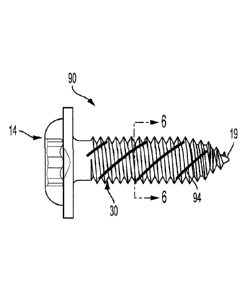
ABSTRACT OF THE DISCLOSURE A fastener has a generally cylindrical shank and a driver at a first end of the shank. The shank has a thread having a first side and a second side opposed to the first side. The first and second sides form a compound angle between the shank and an apex where the first and second sides meet. The compound angle is formed by a body portion extending along the first and second sides from the shank to an intersection, and a crest portion extending along the first and second sides from the intersection to the apex. The first and second sides in the body portion form a body angle with respect to each other, and the first and second sides in the crest portion form a crest angle with respect to each other. The crest angle is greater than the body angle. Date Recue/Date Received 2020-10-05


French Abstract

ABRÉGÉ DE LA DIVULGATION : Une attache comprend une tige généralement cylindrique et un mécanisme dentraînement à une première extrémité de la tige. La tige comprend un filet ayant un premier côté et un deuxième côté opposé au premier côté. Le premier et le deuxième côté forment un angle composé entre la tige et un sommet à la jonction du premier et du deuxième côté. Langle composé est formé dune partie de corps sétendant le long du premier et du deuxième côté à partir de la tige à une intersection et dune partie de crête sétendant le long du premier et du deuxième côté de lintersection au sommet. Le premier et le deuxième côté dans la partie de corps forment un angle de corps et le premier et le deuxième côté dans la partie de crête forment un angle de crête. Langle de crête est plus grand que langle de corps. Date reçue / Date Received 2020-10-05

Claims

Note: Claims are shown in the official language in which they were submitted.


CLAIMS:
1. A fastener comprising:
a generally cylindrical shank having a central longitudinal axis, and
a driver at a first end of the shank, the shank being tapered toward a second
end of the shank opposite to the first end,
the shank further having a thread extending outwardly from the shank, the
thread encircling the shank in a helical manner,
the thread having a first side and a second side opposed to the first side,
the
first and second sides forming a compound angle between the shank and an apex
at
the second end,
the compound angle being formed by a body portion extending along the first
and second sides from the shank to an intersection, and a crest portion
extending
along the first and second sides from the intersection to the apex,
wherein
the first and second sides in the body portion form a body angle with respect
to each other,
the first and second sides in the crest portion form a crest angle with
respect
to each other, and
the crest angle is greater than the body angle.
2. The fastener of claim 1, wherein the crest angle is about two times the
body
angle.
6
Date Recue/Date Received 2022-06-17

3. The fastener of claim 1, wherein the crest angle is between 90 degrees
and
140 degrees.
4. The fastener of claim 1, wherein the body angle is between 30 degrees
and
80 degrees.
5. The fastener of claim 1, wherein the thread extends from the first end
to the
second end.
6. The fastener of claim 1, wherein the second end is flat.
7. The fastener of claim 1, wherein the second end is a tip.
8. The fastener of claim 1, wherein the shank has at least one lobe.
7
Date Recue/Date Received 2022-06-17

Description

Note: Descriptions are shown in the official language in which they were submitted.


FASTENERS FOR HIGH STRENGTH STEEL
This invention relates to fasteners, and more particularly, to fasteners
for high strength steel.
BACKGROUND OF THE INVENTION
[0001] The growth and popularity of higher strength steels (for example,
High
Strength Low Alloy (HSLA), Advanced High Strength Steels (AHSS), etc.) has
allowed for assemblies such as automotive seat frames and bases to be made
with
thinner material because these steels are stronger than previously used
materials.
Such higher strength materials are advantageous because they have higher
strength
characteristics and lower overall ductility as well as reduced weight.
[0002] Typical thread forming fasteners (those creating their own
threads
during assembly) do not perform adequately when used in the new steels,
because
the mating material does not provide adequate ductility allowing for typical
thread
designs to successfully form threads in the mating material. As a result,
performance
during assembly can be very inconsistent and result in poor clamp load being
achieved, loose joints and damage to the threaded product.
[0003] Thus, there is a need for a thread forming design which can
consistently
be used in high strength steels without thread deformation or damage.
1
Date Recue/Date Received 2020-10-05

SUMMARY OF THE INVENTION
[0004] In keeping with one aspect of this invention, a fastener has a
generally
cylindrical shank having a central longitudinal axis, and a driver at a first
end of the
shank. The shank is tapered over some portion from the driver toward a tip on
a
second end of the shank opposite to the first end.
[0005] The shank has a thread encircling the shank from the general area
of
the first end to the second end in a helical manner. The thread consists of
two
different thread angles stacked on top of each other, creating a compound
thread
angle for the thread form. The thread angles are formed by a first side and a
second
side opposed to the first side. The thread form closest to the axis of the
shank forms
a base angle. The base angle is formed by a base portion extending along the
first
and second sides from the shank to an arbitrary intersection. A thread form on
top of
the base angle forms a crest angle. The crest angle is formed by a crest
portion
extending along the first and second sides from the intersection to the apex.
The
crest angle is greater than the body angle.
BRIEF DESCRIPTION OF THE DRAWINGS
[0006] The above mentioned and other features of this invention and the
manner of obtaining them will become more apparent, and the invention itself
will be
best understood by reference to the following description of an embodiment of
the
invention taken in conjunction with the accompanying drawings, in which:
2
Date Recue/Date Received 2020-10-05

[0007] FIG. 1 is a plan view of one embodiment of a fastener of the
present
invention;
[0008] FIG. 2 is a plan view of the head on one end of the fastener of
FIG.1;
[0009] FIG. 3 is a detailed cross-sectional view of the thread form of
the thread
in the fastener of FIG. 1;
[0010] FIG. 4 is an end view of a second end of the fastener of FIG.1;
[0011] FIG. 5 is a side view of a second embodiment of the fastener of
the
present invention, having a lobular shaft and a tip at the second end; and
[0012] FIG. 6 is a sectional view of the base of the fastener of FIG. 5,
taken
along lines A-A.
DETAILED DESCRIPTION
[0013] As seen in FIG. 1, a fastener 10 has a shank 12 and a driver 14
at a
first end 15 of the shank 12. The shank 12 has a longitudinal axis 13. The
driver 14
is shown as a hex head 17 and flange 16. The driver 14 could also be an
alternative
design or a threaded or unthreaded stud.
[0014] The shank 12 is tapered at some point towards a second end 18 of
the
shank 12. The second end 18 can be flat, as seen in FIG. 1 and FIG. 4, or a
tip 19,
as in FIG. 5. The tip 19 can be a sharp point or a partially formed point.
[0015] The shank 12 has a thread 30 extending outwardly from the shank
12.
The thread 30 can extend from the first end 15 to the second end 18, or the
thread
can start at a place removed from or distant from the first end 15.
3
Date Recue/Date Received 2020-10-05

[0016] The thread 30 has first and second sides 34, 36 which are spaced
at
the shank 12 and are angled towards each other until they meet at an apex 38.
The
sides 34, 36 are angled towards each other in a compound angle, as will be
described.
[0017] The compound angle is formed by a generally trapezoidal body
portion
40 extending along the first and second sides 34,36 from the shank 12 to
intersections
42, 44, respectively, and a generally triangular crest portion 50 extending
along the
first and second sides 34, 36 from the intersections 42, 44 to the apex 38.
The
intersections 42, 44 can be fairly sharp, as in FIG. 3, or rounded.
[0018] The body portion 40 is defined generally by an imaginary line 40a

between starting points 41, 43 of the sides 34, 36, respectively, at the shank
12, a
side portion 40b of the side 34, a side portion 40c of the side 36, and an
imaginary
line 40d between the intersections 42, 44. The crest portion 50 is defined
generally
by the imaginary line 40d, a portion 30a of the side 34 between the
intersection 42
and the apex 38, and a portion 30b of the side 36 between the intersection 44
and
the apex 38.
[0019] The side portions 40b, 40c form a body angle B with respect to
each
other, and the side portions 30a, 30b in the crest portion 50 form a crest
angle C with
respect to each other. The crest angle C is greater than the body angle B. The
crest
angle C can be in the range of about 90 to about 140 degrees, and the body
angle B
can be in the range of about 30 degrees to about 80 degrees. A preferred ratio
C/B
i52.
4
Date Recue/Date Received 2020-10-05

[0020] FIGS. 5 and 6 show a second embodiment of the fastener 10 that
includes a lobular shaft described in U.S. Patent No. 5,242,253. A fastener 90
(FIG.
5) includes the threads shown in FIG. 3, but the shank has 3 lobes 94. Each
lobe 94
has an elongated leading leg 96 that spirals around the shank, progressing
gradually
away from the first end 15 of the shank in the direction of turning. Each lobe
94 also
has a trailing leg 98 which abruptly turns inwardly towards the shank axis and
is
shorter than a leading edge leg 96. Lobes 94 are therefore non-symmetrical.
[0021] While the principles of the invention have been described above
in
connection with specific apparatus and applications, it is to be understood
that this
description is made only by way of example and not as a limitation on the
scope of
the invention.
Date Recue/Date Received 2022-06-17

Representative Drawing
A single figure which represents the drawing illustrating the invention.
Administrative Status

For a clearer understanding of the status of the application/patent presented on this page, the site Disclaimer , as well as the definitions for Patent , Administrative Status , Maintenance Fee  and Payment History  should be consulted.

Administrative Status

Title Date
Forecasted Issue Date 2023-02-14
(22) Filed 2020-10-05
(41) Open to Public Inspection 2021-05-18
Examination Requested 2022-05-26
(45) Issued 2023-02-14

Abandonment History

There is no abandonment history.

Maintenance Fee

Last Payment of $100.00 was received on 2023-09-29


 Upcoming maintenance fee amounts

Description Date Amount
Next Payment if standard fee 2024-10-07 $125.00
Next Payment if small entity fee 2024-10-07 $50.00

Note : If the full payment has not been received on or before the date indicated, a further fee may be required which may be one of the following

  • the reinstatement fee;
  • the late payment fee; or
  • additional fee to reverse deemed expiry.

Patent fees are adjusted on the 1st of January every year. The amounts above are the current amounts if received by December 31 of the current year.
Please refer to the CIPO Patent Fees web page to see all current fee amounts.

Payment History

Fee Type Anniversary Year Due Date Amount Paid Paid Date
Application Fee 2020-10-05 $400.00 2020-10-05
Request for Examination 2024-10-07 $814.37 2022-05-26
Maintenance Fee - Application - New Act 2 2022-10-05 $100.00 2022-09-30
Final Fee 2022-12-16 $306.00 2022-11-17
Maintenance Fee - Patent - New Act 3 2023-10-05 $100.00 2023-09-29
Owners on Record

Note: Records showing the ownership history in alphabetical order.

Current Owners on Record
SEMBLEX CORPORATION
Past Owners on Record
None
Past Owners that do not appear in the "Owners on Record" listing will appear in other documentation within the application.
Documents

To view selected files, please enter reCAPTCHA code :


To view images, click a link in the Document Description column. To download the documents, select one or more checkboxes in the first column and then click the "Download Selected in PDF format (Zip Archive)" or the "Download Selected as Single PDF" button.

List of published and non-published patent-specific documents on the CPD .

If you have any difficulty accessing content, you can call the Client Service Centre at 1-866-997-1936 or send them an e-mail at CIPO Client Service Centre.


Document
Description 
Date
(yyyy-mm-dd) 
Number of pages   Size of Image (KB) 
New Application 2020-10-05 5 140
Abstract 2020-10-05 1 20
Description 2020-10-05 5 161
Claims 2020-10-05 2 39
Drawings 2020-10-05 2 31
Request for Examination 2022-05-26 3 74
PPH Request / Amendment 2022-06-17 12 394
PPH OEE 2022-06-17 2 116
Description 2022-06-17 5 226
Claims 2022-06-17 2 56
Early Lay-Open Request 2022-06-17 6 220
Final Fee 2022-11-17 3 67
Representative Drawing 2023-01-06 1 6
Cover Page 2023-01-06 1 37
Representative Drawing 2023-01-18 1 5
Cover Page 2023-01-18 1 37
Electronic Grant Certificate 2023-02-14 1 2,527