Note: Descriptions are shown in the official language in which they were submitted.
GRAIN AERATION SYSTEM
TECHNICAL FIELD
[0001] Grain aeration system.
BACKGROUND
[0002] Reducing moisture in stored grain is important for grain quality,
safety and storage. Grain
aeration systems are used to dry grain within a grain bin. Some systems
include tubes and other
heat/air distribution systems that heat grain from the bottom or only the
lowermost section of a
grain bin. This causes overdrying of the grain at the bottom of the bin and
creates a dry line above
which moisture is not removed or insufficiently removed from the grain. Grain
above the dry line
may remain at an initial grain moisture similar to the initial seed moisture,
which may be in the
range of 14 to 20 percent moisture content depending on the type of grain.
Depending on the type
of grain, moisture content below 10 percent may be necessary to ensure no
spoilage of grain for
storage for months at a time. Some known grain aeration systems do not
adequately heat or add
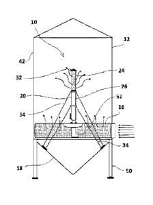
air to the grain in the top of a grain bin while overheating the grain at or
near the bottom.
SUMMARY
[0003] There is provided in one embodiment a grain aeration system for a grain
bin. The system
comprises a gas entry duct configured to receive gas, the gas entry duct
extending along a base of
the grain bin and a gas distribution pipe extending upwardly from the gas
entry duct and having a
height. The gas distribution pipe comprises a permeable section in an upper
portion of the gas
distribution pipe. The permeable section comprising a plurality of
perforations.
[0004] In various embodiments, there may be included any one or more of the
following
features: the gas distribution pipe having an impermeable section and the
impermeable section
being below the permeable section, a heater to supply heated gas to the gas
entry duct; the
impermeable section extends from the gas entry duct to a distance more than
half the height of
the gas distribution pipe; the gas distribution pipe comprises a vertical
tube; the impermeable
section extends from the gas entry duct to a distance more than forty percent
of the height of the
gas distribution pipe; the plurality of perforations extend to a top of the
gas distribution pipe; a
cone deflector is mounted above the permeable section; at least three guy
wires attached to the
1
Date Recue/Date Received 2020-10-06
gas distribution pipe; the heater is a blower; the blower further comprises: a
gas intake, a fan
configured to draw air from the intake, an external burner, a heat exchanger
in fluid connection
with the external burner, the heat exchanger being downstream of the intake,
and an outlet
downstream of the heat exchange, the outlet being connected to the gas entry
duct; the gas entry
duct comprises a horizontal tube; a gas flow redirector connected to a base of
the gas distribution
pipe to direct gas from the gas entry duct into the gas distribution pipe; and
the gas flow
redirector is a gas flow scoop.
[0005] There is provided in one embodiment a grain bin, comprising a
surrounding wall and
roof, a gas entry duct extending from outside the surrounding wall to inside
the surrounding wall
and a gas distribution pipe extending upward from the gas entry duct, the gas
distribution pipe
having a permeable section in an upper portion of the gas distribution pipe.
[0006] In various embodiments, there may be included any one or more of the
following
features: the gas distribution pipe having an impermeable section below the
permeable section, a
heater placed to heat gas that passes through the gas entry duct or gas
distribution pipe; the roof
is conical with an apex and the gas distribution pipe is inline with the apex;
the permeable
section is shorter than the impermeable section; and the gas is air sourced
from outside the
surrounding wall.
[0007] These and other aspects of the system and method are set out in the
claims, which are
incorporated here by reference.
BRIEF DESCRIPTION OF THE FIGURES
[0008] Embodiments will now be described with reference to the figures, in
which like reference
characters denote like elements, by way of example, and in which:
[0009] Fig. 1 is a side schematic view of an embodiment of a grain aeration
system.
[0010] Fig. 2 is a side schematic view of a blower for a grain aeration
system.
[0011] Fig. 3 is a side schematic view of another embodiment of a grain
aeration system.
[0012] Fig. 4 is a side schematic view of another embodiment of a grain
aeration system.
[0013] Fig. 5 is a side schematic view of an embodiment of a grain aeration
system in a flat bottom
bin.
[0014] Fig. 6 is a top schematic view of an embodiment of a grain aeration
system with two gas
distribution pipes in a large flat bottom bin.
2
Date Recue/Date Received 2020-10-06
[0015] Fig. 7 is a side schematic view of an embodiment of a gas distribution
pipe having openings
in a lower portion of the pipe.
[0016] Figs. 8-10 are side schematic views of embodiments of gas distribution
pipes having
different shapes.
[0017] Fig. 11 is a side schematic view of a gas distribution pipe mounted on
a support plate.
[0018] Fig. 12 is a side schematic view of a gas distribution pipe having
support rods and a collar.
[0019] Fig. 13 is an isometric side schematic view of a gas distribution pipe
and a gas entry duct
with a dampener.
[0020] Fig. 14 is an isometric side schematic view of an actuator for opening
and closing the
dampener in Fig. 13.
[0021] Fig. 15 is a close up cutaway side schematic view of cone deflector on
a joint of a gas
distribution pipe.
[0022] Fig. 16 is a side schematic view of the cone deflector on a joint of a
gas distribution pipe
of Fig. 15.
DETAILED DESCRIPTION
[0023] In Figs. 1, 3 and 4 there are disclosed embodiments of a grain aeration
system 10 for a
grain bin 12. The grain aeration system may be called the "GO Tech Air
MissileTM.
[0024] The grain bin 12 includes a surrounding wall 42 and roof 44. A gas
entry duct 16 extends
from outside the surrounding wall 42 to inside the surrounding wall and a gas
distribution pipe 20
extends upward from the gas entry duct 16. The gas distribution pipe 20 has a
permeable section
24 in an upper portion of the gas distribution pipe. As shown in Fig. 1, the
permeable section 24
is above an impermeable section 26. Although in Fig. 1, the impermeable
section 26 is shown as
allowing no gas flow through the gas distribution pipe 20, the system will
operate even if there is
some, but reduced, flow through a lower portion of the gas distribution pipe
20 as compared to the
upper permeable section.
[0025] There is a heater 14 exterior to the grain bin 12. The heater 14 is
placed to heat gas that
passes through the gas entry duct 16 or gas distribution pipe 20. The heater
may be, for example,
a standard blower or a blower 100 as shown in Fig. 2. Any suitable source of
heated gas may be
used. Separate heaters may be used for the gas entry duct 16 and the gas
distribution pipe 20. In
embodiment shown in Figs. 1, 3 and 4, the gas is air sourced from outside the
surrounding wall.
3
Date Recue/Date Received 2020-10-06
Other sources of gas may also be used. The heater could be inline in either
the gas entry duct or
the gas distribution pipe. Heated gas maybe also be provided by passive solar
heat, including, for
example, a lens placed over the gas distribution pipe outside the bin.
[0026] The roof 44 is conical with an apex 48 and the gas distribution pipe 20
is inline with the
apex 48. As shown in Fig. 1, the permeable section 24 is shorter than the
impermeable section 26.
The gas distribution pipe 20 has a top 30 and the surrounding wall has an
upper edge 46.
[0027] The gas entry duct 16 is configured to receive heated gas from the
heater 14. The gas
entry duct 16 extends along a base 18 of the grain bin 12. The gas entry duct
16 is a horizontal
tube that extends along the full width of the grain bin 12 and includes a
plurality of perforations
36. The perforations 36 may extend along the entire length of the gas entry
duct 16. The gas
entry duct 16 may extend from one side of the grain bin to the other or may
extend only across a
portion of the grain bin. Although the gas entry duct 16 is shown as a single
horizontal tube, the
gas entry duct may be one of several tubes or may be a tube with various
curves and twists. The
gas entry duct 16 does not need to have a uniform height along its length. The
gas entry duct may
have any configuration or shape so long as it supplies sufficient gas to dry
grain in the lower
portion of the grain bin. If the ambient air is over 15 degrees Celsius, a
heater may not be
needed, and the aeration fans can be run without a heat source to dry grain.
[0028] The gas distribution pipe 20 extends upwardly from the gas entry duct
16. The gas
distribution pipe 20 is a vertical tube and has a height 22. The permeable
section 24 has a
plurality of perforations 28. The height 22 of the gas distribution pipe may
be in the range of 40
to 80 percent of a height 38 of the grain bin. The gas distribution pipe may
have a variety of
diameters. Preferably, the diameter of the gas distribution pipe will be no
less than four inches.
The gas distribution pipe 20 does not need to be precisely vertical and can
have various curves
and twists. The gas distribution pipe 20 may have a variety of shapes and
orientations so long as
it supplies sufficient heat to dry grain in the upper portion of the grain
bin. The gas distribution
pipe may be one of a plurality of tubes that extend upwardly within the grain
bin. The heated gas
will rise in the bin, and so the permeable section 24 of the gas distribution
pipe 20 is preferably
placed in the middle or upper-middle portion of the bin.
[0029] The impermeable section 26 may extend from the gas entry duct 16 to a
distance more
than half the height 22 of the gas distribution pipe. The impermeable section
26 may extend
more than forty percent of the height of the gas distribution pipe 20. As
shown in Fig. 1, the
4
Date Recue/Date Received 2020-10-06
impermeable section 26 extends from the gas entry duct 16 to approximately
sixty percent of the
height 22 of the gas distribution pipe. The plurality of perforations 28
extend from approximately
sixty percent of the height 22 of the gas distribution pipe to the top 30 of
the gas distribution
pipe. The impermeable section 26 may not extend to the base of the gas
distribution pipe 20. The
base distribution pipe 20 may include a small section of perforations near the
base of the gas
distribution pipe, so long as the impermeable section 26 of the gas
distribution pipe provides a
vertical section where heated gas is not introduced into the grain bin below
the permeable section
24. In contrast, a vertical tube having continuous and equally-sized
perforations from the base of
the grain bin to an upper-level in the bin could cause overdrying of the grain
below a certain
height and insufficient drying about that height.
[0030] A cone deflector 32 is mounted above the permeable section of the gas
distribution pipe
to deflect grain that is supplied into the grain bin. The cone deflector 32
may extend, for
example, half an inch beyond the outer diameter of the bin to take the
pressure off of the tube
when grain is being loaded and unloaded.
[0031] The gas distribution pipe may be supported by at least three guy wires
34 attached to the
gas distribution pipe 20. As shown in Fig.1, there are four guy wires 34.
Preferably, there will be
guy wires 34 attached to the top section (Fig. 4) and in the middle of the gas
distribution pipe,
with a minimum of three wires at each location. Alternatively, the gas
distribution pipe may be
supported at the base of the bin using at least three support rods (Figs. 11
and 12), which could
extend up to the base of the permeable section of the gas distribution pipe.
Various designs of
supports may be used so long as the supports ensure that the gas distribution
pipe does not
collapse during normal operation. As shown in Fig. 4, the grain bin 12 itself
may be supported on
supports 50.
[0032] As shown in Fig. 4, there is a gas flow redirector, such a gas flow
scoop 52, at the base of
the gas distribution pipe 20 to grab gas, such as air, from the gas entry duct
16 to redirect it
towards gas distribution pipe 20. The gas flow redirector increases the
distribution of gas into the
gas distribution pipe 20. Various designs of gas flow redirector may be used
to increase the
distribution of gas into the gas distribution pipe.
[0033] In some embodiments, by providing a gas distribution pipe 20 that
injects gas from an
upper portion of the tube, but not the lower portion, more equal drying may be
achieved within
the bin. In some current drying systems, heating may be performed only from
the base of the
Date Recue/Date Received 2020-10-06
grain bin. This causes substantial drying in the lower portion of the grain
bin, but may leave
inadequate drying in the upper portion of the bin. Similarly, even if systems
that use vertical
tubes were used that were equally perforated along their full heights, those
tubes would still heat
unevenly by heating the lower portions of the grain bin more than the upper
portions. By having
the impermeable section of solid pipe extend, for example, two thirds of the
way up the gas
distribution pipe, gas flow is added to the top of the bin to push the
excessive moisture out the
top and stop the overdrying at the bottom.
[0034] As shown in Fig. 2, there is a blower 100 having a gas intake 102, a
fan 104 configured to
draw gas, such as air, from the intake 102, an external burner 106, a heat
exchanger 108 in fluid
connection with the external burner 106 and an outlet 110 downstream of the
heat exchanger
108. During operation, the outlet 110 of the blower is connected to an inlet
40 (Fig. 1) of the gas
entry duct. The blower 100 draws gas into the inlet 102 by the operation of
the fan 104 within the
blower and pushes the gas to the heat exchanger 108, which is downstream of
the intake 102.
Heated gas that passes the heat exchange 108 is pushed out the outlet 110 of
the blower 100. The
external burner 106 may alternatively be placed within the blower 100 so long
as exhaust does
not enter the stream of heated gas that goes into the grain bin.
[0035] By sending gas past heat exchanger 108 to heat the gas up, the burner
106 and heat
exchanger 108 vent to the outside of the gas stream through an exhaust 112.
This is different
from standard burner designs which may send exhaust gas directly into the
grain bin with the
heated gas. By removing burner exhaust from the stream of heated gas entering
the grain bin, all
the water vapour from combustion is kept out of the grain, thus allowing the
grain to dry faster.
[0036] Fig. 3 shows another embodiment of a grain bin aeration system 10. For
simplicity, support
structures such as guy wires are not shown. As compared to the embodiment
shown in Fig. 1, the
permeable section 24 of the gas distribution pipe 20 has a shorter height. The
permeable section
24 has a height less than a third of the full height of the impermeable
section 26. By providing the
permeable section 24 in the middle to upper half of the grain bin, more even
drying of the grain
may be provided as compared to traditional systems. By adding extra gas at the
top of the grain
bin, rather than along the entire length of the gas distribution pipe,
moisture is pushed out of the
entire bin. In some embodiments, this allows for more even drying throughout
the bin.
6
Date Recue/Date Received 2020-10-06
[0037] Fig. 5 shows an embodiment of grain aeration system 10 with a grain bin
12 having a flat
bottom. In this embodiment, the guy wires 34 are attached to the walls 42 of
the grain bin 12. The
gas entry duct 16 is placed directly along the flat base 18 of the grain bin
12.
[0038] In some bigger flat bottom bins, the grain aeration system may include
multiple gas
distribution pipes extending upwardly within the bin. The systems may include
multiple gas entry
ducts extending from outside the surrounding wall to inside the surrounding
wall and multiple gas
distribution pipes extending upward from each of the gas entry ducts. The gas
distribution pipes
may be spaced within the grain bin to allow for maximum drying. In other
embodiments only one
gas entry duct may be used that is connected to and supplies gas, such as air,
to multiple gas
distribution pipes.
[0039] Fig. 6 shows an embodiment of a grain aeration system 210 having
multiple gas distribution
pipes 20A, 20B and a gas entry duct 16 having a single exterior inlet. The gas
entry duct 16 is split
by a divider 60 into two gas entry duct sections 16A, 16B. Each of the gas
entry duct sections 16A
and 16B has the corresponding gas distribution pipe 20A and 20B, respectively,
extending
upwardly from the corresponding gas entry duct section. Each of the gas
distribution pipes 20A
and 20B may have a design the same as one of the gas distribution pipes 20
shown in the
embodiments of Figs. 1, 3 or 4. The specific design and orientation of the gas
distribution pipes
20A and 20B and the gas entry ducts may be chosen based on the size and
orientation of the grain
bin, the type of grain being dried, exterior air temperature, energy
efficiency and other relevant
factors. Each of the gas entry duct sections 16A and 16B are perforated. The
portion of the gas
entry duct 16 from the inlet to the divider 60 may also be perforated as shown
in Fig. 6. The
placement of the perforations of the gas entry duct 16 may be selected based
on various factors
such as the size and orientation of the bin, the type of grain being dried,
exterior air temperature
and other relevant factors.
[0040] As shown in Fig. 7, rather than having a lower impermeable section 26
as shown in Fig. 1,
there may be some perforations extending in a lower portion 126 of a gas
distribution pipe 100 so
long as the perforations are smaller or fewer than in a permeable section 124
in an upper portion
so as to allow reduced flow in the lower section. The airflow through the
permeable section 124
in an upper portion of the gas distribution pipe is preferably between 10 and
40 percent of the
airflow into the grain bin while almost all of the remainder moves through the
gas entry duct 16
(Fig. 1). The flow through the lower portion 126 of the gas distribution pipe
may be minimal or
7
Date Recue/Date Received 2020-10-06
the lower portion may be fully impermeable. As shown in Fig. 7, the
perforations 128 extend from
the gas entry duct to the top of the gas distribution pipe, but are higher in
number and/or size in
the permeable section 124 of the gas distribution pipe. In some embodiments,
there is a prorated
design in which the openings in the gas distribution pipe get larger as the
height is increased. The
size of the holes may start small on the lower portions and get larger going
up to the distribution
pipe or there may be more holes the higher up the distribution pipe. So long
as a balance can be
provided between drying the grain in the upper portion of the bin by the
permeable section 124
and the grain in the lower portion of the bin provided by the lower portion
124 and gas entry duct,
the location and sizes of openings in the gas distribution pipe and gas entry
duct may be rearranged.
The lower section between the permeable upper section and the gas entry duct
can have no
perforations, or could have perforations, depending on the corresponding
airflow between the gas
entry duct and the upper section of the gas distribution pipe. In some
embodiments, it may be
possible to have more extensive perforations having more gas flow in the lower
section of the gas
distribution pipe if there less extensive perforations having less gas flow in
the gas entry duct.
[0041] In some embodiments there may be multiple sections of permeable
sections at different
heights along the gas distribution pipe. For example, the gas distribution
pipe may have in addition
to a permeable section at an upper portion of the gas distribution pipe, an
additional gas permeable
section in the middle part of the gas distribution pipe, for example, for bins
taller than 20 feet.
[0042] Fig. 8 shows a gas distribution pipe 200 having a polygonal cross-
section 220. Various
different shapes of gas distribution pipes may be used. As shown in Fig. 9, a
gas distribution pipe
300 may have a square cross-section 320. As shown in Fig. 10, different
sections of a gas
distribution pipe 400 may have different shapes. A lower portion of a gas
distribution pipe, for
example, an impermeable section 426 may be cylindrical 420 whereas an upper
portion of a gas
distribution pipe, for example, a permeable section 424 may have a polygonal
cross-section.
[0043] Figs. 11 and 12 show a gas distribution pipe 500 having a lower
impermeable section 526
and an upper permeable section 524. A number of rods 554 provide middle
support in addition to
guide wires 534 and connect to a collar 556. The collar 556 may sit between
the permeable and
impermeable sections as shown, or may be placed in other locations along the
gas distribution
pipe. The collar 556 may have a loose fit or may be tightened on. As shown in
Fig. 11, the gas
distribution pipe may be mounted on a support plate 558 which is fixed to bin
supports (not shown).
8
Date Recue/Date Received 2020-10-06
[0044] Figs. 13-16 show a gas distribution pipe 620 and a gas entry duct 612
where the gas entry
duct includes a dampener 662 for changing the amount of gas flow into the gas
distribution pipe.
The gas distribution pipe 620 has a permeable section 624 above an impermeable
section 626 and
the gas distribution pipe 620 is a series of pipes joined together and there
are cone deflectors 660
between each joint. There is also a top cone deflector 632 mounted above the
permeable section
624.
[0045] As shown in Fig. 14, the dampener 662 may be actuated by a spring
tensioned lever 664
which is connected to the dampener by corresponding arms 668 and 670 with
rigid or tensioned
connections (not shown) between them. Controlling the dampener provides for
control of the
amount of gas flow into the gas distribution pipe. Control of gas flow into
the gas distribution pipe
may be controlled in various ways including various designs of dampeners. In
some embodiments,
the dampener may be opened and closed by being actuated remotely.
[0046] As shown in Figs. 15 and 16, there are cone deflectors 660 between
joints of the gas
distribution pipe 620. The joints of pipe may be joined using a flange 672 and
various attachment
mechanisms 674.
[0047] Immaterial modifications may be made to the embodiments described here
without
departing from what is covered by the claims. For example, various different
sizes, shapes and
orientations of perforations are possible. Perforations do not need to be
uniformly spaced on the
permeable section of the gas distribution pipe. The term perforation is used
to refer to any openings
in the tube that allow heated gas to escape from the tube. A permeable section
may have any
structure as long as gas flow is permitted from within the pipe to outside of
the pipe. For example,
the permeable sections of the gas distribution pipe could include small
sections of pipe that are
both permeable and impermeable so long as the collective whole allows for gas
flow into a nearby
section of the grain bin. The gas distribution pipe and gas entry duct may be
tubes having any
shapes or design and do not need to be cylindrical in shape. The number,
orientation and shape of
gas entry ducts and gas distribution pipes may be chosen based on the size and
orientation of the
grain bin, the type of grain being dried, exterior air temperature, energy
efficiency and other
relevant factors, so long as beneficial distribution of drying of the grain
within the bin may be
achieved.
[0048] In the claims, the word "comprising" is used in its inclusive sense and
does not exclude
other elements being present. The indefinite articles "a" and "an" before a
claim feature do not
9
Date Recue/Date Received 2020-10-06
exclude more than one of the feature being present. Each one of the individual
features described
here may be used in one or more embodiments and is not, by virtue only of
being described here,
to be construed as essential to all embodiments as defined by the claims.
Date Recue/Date Received 2020-10-06