Note: Descriptions are shown in the official language in which they were submitted.
CA 03095521 2020-09-29
WO 2019/193103 PCT/EP2019/058524
Absorbent article with reduced absorbent core
TECHNICAL FIELD
The present invention pertains to the technical field of absorbent articles,
more preferably
disposable personal care articles such as diapers, baby pants, adult
incontinent garments, and the
like, and to absorbent structures for use in such absorbent articles. More
specifically the present
invention relates to an absorbent structure comprising an absorbent core
between a topsheet and a
backsheet. The present invention also relates to a method and apparatus for
manufacturing such an
absorbent article.
BACKGROUND
Disposable absorbent articles have an absorbent structure for absorbing bodily
exudates, a soft
liquid-permeable top sheet on the wearer side and a liquid- impermeable back
sheet on the garment
side. The absorbent structure in between is normally made from a mixture of
cellulose fibers or
other fibrous substance and an absorbent polymer material. These fibrous
substances make these
absorbent articles typically quite fluffy and bulky.
In recent years there has been increasing demand for flexible, thinner,
lightweight absorbent
structures to resolve various problems of manufacturing, marketing, design,
fit, wearing comfort,
distribution, garbage disposal, material and energy consumption,
transportation and storage costs
and the like.
The most common method currently used to meet these demands in disposable
absorbent articles is
.. to reduce the amount of cellulose fibre or other support material within
and surrounding the
absorbent structure and/or use larger amounts of absorbent polymer materials.
Consequently such
absorbent articles have a smaller proportion of hydrophilic cellulose fibres
and/or a higher
proportion of absorbent polymers materials. Some of these absorbent articles
may be better at
storing liquid, however they are not necessarily good at absorbing and
distributing liquid when the
absorbent article is actually being used. It will thus be apparent from the
above that the absolute
and relative proportions of the fibrous material and absorbent polymer
material are closely linked
in light of article performance.
In order to obtain good absorbency, distribution and retention within such
absorbent structures it
has found to be important to at least partially immobilize the absorbent
material. Failing to provide
sufficient structural integrity results in loss of functional performance
characteristics such as
coherence, absorption, distribution and/or retention and results in failures
related but not limited to
for instance leakages, high rewet values, etc.
CA 03095521 2020-09-29
WO 2019/193103 PCT/EP2019/058524
2
EP 2 627 294 relates to a method and apparatus for forming a composite
structure, preferably for
use in an absorbent structure used within the personal hygiene industry, such
as for instance
feminine hygiene garments, baby diapers and pants and adult incontinence
garments. The invention
preferably provides a method and apparatus for depositing and positioning
particulate materials in
a desired pattern onto a moving carrier layer. The method allows accurate
forming of a pattern of
particulate material clusters at high production speed having improved
attachment properties, with
reduced raw material usage and relative low cost.
WO 2012/052173 relates to a method and apparatus for forming a composite
structure, preferably
for use in an absorbent structure used within the personal hygiene industry,
such as for instance
feminine hygiene garments, baby diapers and pants and adult incontinence
garments. The method
comprises depositing particulate material in a desired pattern onto a moving
carrier layer and
positioning it into a pocketing pattern. The method allows accurate forming of
a pre-determined
pattern of particulate material clusters at high production speed, with
reduced raw material usage
and relative low cost. As such method allows manufacturing of absorbent
structures being
substantially cellulose free and substantially glue free, considered
technically, economically and
environmentally friendly.
There is a need in the art for an improved thin, flexible, lightweight
absorbent structure which is
discreet, sustainable and/or relatively inexpensive taking in mind
manufacturing, marketing,
design, fit, comfort, distribution, packaging, disposal, material, energy and
transportation costs
while preserving the required fluid absorption, distribution, transport,
coherence and retention
properties. There is furthermore also a need for a method and apparatus to
produce such absorbent
structures at high production speed and low energy and raw material
consumption.
SUMMARY
The object of embodiments of the invention is to provide an absorbent article
of the type stated in
the preamble, with reduced manufacturing cost, light weight, thin, and good
liquid distribution and
absorption capacities.
According to a first aspect of the invention, there is provided an absorbent
article comprising a
liquid pervious topsheet, a liquid impervious backsheet, and an absorbent core
positioned between
the liquid pervious topsheet and the liquid impervious backsheet. The
absorbent article has a first
and second longitudinal edge and a first and second transverse edge. The
absorbent core comprises
a top core sheet, a back core sheet, and absorbent material arranged partially
between the top core
sheet and the back core sheet. At least one of the top core sheet and the back
core sheet comprises
at least one attachment portion which is attached to the other one of the top
core sheet and the back
CA 03095521 2020-09-29
WO 2019/193103 PCT/EP2019/058524
3
core sheet forming at least one attachment zone, and at least one edge portion
having at least one
free edge and covering a portion of the absorbent material.
By providing at least one of the top core sheet and the back core sheet with
at least one edge
portion having at least one free edge and covering a portion of the absorbent
material, the at least
one of the top core sheet and the back core sheet does not cover the entire
top and/or bottom
surface of the absorbent material, resulting in less raw material needed for
the absorbent core. The
at least one attachment portion forms at least one attachment zone capable of
creating a channel for
liquid distribution and absorption upon wetting. In this manner, at least one
channel can be created
with a reduced amount of material used for manufacturing the top core sheet
and/or back core sheet,
and as a result the manufacturing cost can be reduced while good liquid
distribution and absorption
capacities can be maintained. In addition, the thickness and weight of
absorbent article may be
reduced.
It is noted that either the top core sheet or the back core sheet may have a
free edge and hence a
reduced surface area compared to an absorbent core of the prior art which
fully wraps the
absorbent material, or both the top core sheet and the back core sheet may
have a free edge.
In an exemplary embodiment, seen in a top view of the absorbent core, the top
core sheet has a
total surface area of Si, the back core sheet has a total surface area of S2,
the absorbent core has a
surface area of SO defined by an area covered by the absorbent material plus
an area of the at least
one attachment zone, wherein Si is smaller than 90% of SO and/or S2 is smaller
than 90% of SO.
In an exemplary embodiment, Si and/or S2 is smaller than 80% of SO, preferably
Si and/or S2 is
smaller than 70% of SO, more preferably Si and/or S2 is smaller than 60% of
SO, even more
preferably Si and/or S2 is smaller than 50% of SO, most preferably Si and/or
S2 is smaller than
40% of SO.
In an exemplary embodiment, in the at least one attachment zone substantially
no absorbent
material is present between the top core sheet and the back core sheet,
preferably the at least one
attachment zone is a continuous zone with substantially no absorbent material
arranged between
the top core sheet and the back core sheet, which allows the formation of at
least one channel upon
wetting and hence a better liquid distribution throughout the absorbent core,
enabling better liquid
absorbance.
In an exemplary embodiment, the at least one edge portion comprises a first
edge portion and a
second edge portion located at opposite sides of the at least one attachment
portion. This provides a
stable structural basis for the formation of channel after the absorbent core
is wetted, and results in
the formation of tubes which provide a tub shape to the absorbent core.
CA 03095521 2020-09-29
WO 2019/193103 PCT/EP2019/058524
4
In an exemplary embodiment, the at least one attachment zone comprises an
attachment zone
extending from a crotch region in the direction of the first and/or second
transverse edge of the
absorbent core, and/or an attachment zone extending in the direction from the
first longitudinal
edge to the second longitudinal edge of the absorbent core. It allows a better
liquid distribution
between crotch region and front and/or back portion of absorbent article,
and/or between left and
right portions of absorbent article.
In an exemplary embodiment, the top core sheet and/or the back core sheet has
a substantially
rectangular shape.
In an exemplary embodiment, the top core sheet and/or the back core sheet has
a longitudinal
dimension which is at least 20% of a length of the absorbent core, preferably
at least 30%, more
preferably at least 50%, even more preferably substantially 100% of the length
of the absorbent
core, which allows formation of a longer channel over a larger longitudinal
dimension of the
absorbent core and a better liquid distribution over the absorbent core.
In an exemplary embodiment, the top core sheet and/or the back core sheet has
a transverse
dimension which is at least 5% of a width of the absorbent core, preferably at
least 10%, more
preferably at least 20%, which allows a better liquid distribution over a
larger transverse dimension
of the absorbent core.
In an exemplary embodiment, a longitudinal dimension of the top core sheet
and/or the back core
sheet and the length of the absorbent core are within 10% difference,
preferably substantially the
same. It allows an attachment between the top core sheet and the back core
sheet by the first and
second transverse edge of the absorbent core, providing a stable structure of
the absorbent core
while the use of material can still be reduced.
In an exemplary embodiment, a transverse dimension of the top core sheet
and/or a transverse
dimension of the back core sheet and the width of the absorbent core are
within 10% difference,
preferably substantially the same. It allows an attachment between the top
core sheet and the back
core sheet by the first and second longitudinal edge of the absorbent core,
providing a stable
structure of the absorbent core while the use of material can still be
reduced.
In an exemplary embodiment, a rear and front edge of the top core sheet is
attached to a rear and
front edge of the back core sheet, respectively, providing a more stable
structure of the absorbent
core while the use of material can still be reduced.
In an exemplary embodiment, the absorbent article further comprises a second
top core sheet
comprising at least one second attachment portion which is attached to the
back core sheet forming
at least one second attachment zone, and at least one second edge portion
having at least one free
edge and covering a portion of the absorbent material. In this manner, a
second channel can be
CA 03095521 2020-09-29
WO 2019/193103 PCT/EP2019/058524
created with a reduced amount of material for manufacturing both the top core
sheet and back core
sheet, as a result the liquid distribution and absorption capacities of the
absorbent core is further
improved with a reduced manufacturing cost.
In an exemplary embodiment, the absorbent article further comprising a second
top core sheet and
5 a second back core sheet, said second top core sheet comprising at least
one second attachment
portion which is attached to the second back core sheet forming at least one
second attachment
zone, and at least one second edge portion having at least one free edge and
covering a portion of
the absorbent material. In this manner, a second channel can be created with a
reduced amount of
material for manufacturing both the top core sheet and back core sheet, as a
result the liquid
distribution and absorption capacities of the absorbent core is further
improved with a reduced
manufacturing cost.
In an exemplary embodiment, the absorbent article further comprising a second
back core sheet,
said second back core sheet comprising at least one second attachment portion
which is attached to
the top core sheet forming at least one second attachment zone , and at least
one second edge
portion having at least one free edge and covering a portion of the absorbent
material. In this
manner, a second channel can be created with a reduced amount of material for
manufacturing the
back core sheet, as a result the liquid
In an exemplary embodiment, a distance between the top core sheet and the
second top core sheet
is at least 5% of the width of the absorbent core, which allows a sufficient
manufacturing cost
reduction.
In an exemplary embodiment, a distance between the back core sheet and the
second back core
sheet is at least 5% of the width of the absorbent core, which allows a
sufficient manufacturing cost
reduction.
In an exemplary embodiment, the at least one attachment zone comprises at
least one first
attachment zone and at least one second attachment zone, which allows the
creation of at least two
channels using the at least one of the top core sheet and the back core sheet.
In this manner the
quantity of liquid that can be temperately held is further increased. In
addition, as the total area of
the attachment increases accordingly, and the liquid can be more evenly
distributed over the entire
absorbent core.
In an exemplary embodiment, said at least one first and second attachment
zones extend next to
each other from the crotch region in the direction of the first and/or the
second transverse edge,
which allows a better liquid distribution between crotch region and front
and/or back portion of
absorbent article.
CA 03095521 2020-09-29
WO 2019/193103 PCT/EP2019/058524
6
In an exemplary embodiment, said at least one first and second attachment
zones are connected
through at least one semi-permanent attachment zone, preferably extending in a
substantially
transverse direction, so that liquid can flow in a transverse direction
through the absorbent material
of the absorbent core.
In an exemplary embodiment, the absorbent article further comprises adhesive
between the
absorbent core and the liquid pervious topsheet.
In an exemplary embodiment, the absorbent article further comprises an
acquisition and
distribution layer ADL, positioned between the absorbent core and the liquid
pervious topsheet.
This serves to slow down the flow so that the liquid has adequate time to be
absorbed by and
evenly distributed over the absorbent core.
In an exemplary embodiment, the absorbent article comprises adhesive between
the absorbent core
and the ADL, and/or the absorbent article comprises adhesive between the ADL
and the liquid
pervious topsheet.
In an exemplary embodiment, the at least one attachment zone has a center
line, preferably the
center line is a straight line, or a curve, or a polyline.
In an exemplary embodiment, the at least one attachment zone comprises a
plurality of attachments
zones which have substantially no absorbent material between the top core
sheet and the back core
sheet, and wherein absorbent material is present in an area in-between said
plurality of attachment
zones, between the top core sheet and the back core sheet.
In an exemplary embodiment, a contour of the or each attachment zone is
adjacent to absorbent
material.
In an exemplary embodiment, a length of the or each attachment zone is larger
than 10% of the
length of the absorbent core, more preferably larger than 30%, even more
preferably larger than
50%, which allows a better liquid distribution over a large area of the
absorbent core.
In an exemplary embodiment, said at least one attachment zone comprises at
least one permanent
attachment zone which remains attached when wetted, which allows the channel
to distribute liquid
during further liquid insults.
In an exemplary embodiment, the absorbent material comprises cellulosic fluff
pulp and/or
superabsorbent particles.
According to a second aspect of the invention, there is provided a method for
manufacturing an
absorbent article. The method comprising:
CA 03095521 2020-09-29
WO 2019/193103 PCT/EP2019/058524
7
¨ preparing a absorbent core by providing a top core sheet and a back core
sheet, and by
arranging absorbent material partially between the top core sheet and the back
core sheet. The top
core sheet is attached to the back core sheet forming at least one attachment
zone, and the attaching
is such that at least one of the top core sheet and the back core sheet has at
least one edge portion
having at least one free edge and covering a portion of the absorbent
material; and
¨ including the absorbent core between a liquid pervious topsheet and a
liquid impervious
backsheet.
By attaching the top core sheet and the back core sheet such that at least one
of the top core sheet
and the back core sheet has at least one edge portion having at least one free
edge and covering a
portion of the absorbent material, the at least one of the top core sheet and
the back core sheet does
not cover the entire top and/or bottom surface of the absorbent material, and
may be only located
where the at least one attachment portion is formed to create a channel for
liquid distribution and
absorption upon wetting. In this manner, at least one channel can be created
with a reduced amount
of material used for manufacturing the top core sheet and/or back core sheet,
and as a result the
manufacturing cost can be reduced while good liquid distribution and
absorption capacities can be
maintained. In addition, the thickness and weight of the absorbent article may
be reduced.
In an exemplary embodiment, the top core sheet and the back core sheet are fed
continuously in a
transport direction in the form of a web top core material and a web back core
material having a
first width and a second width, seen in a direction perpendicular on the
transport direction,
respectively; wherein the absorbent material is arranged such that, seen in a
direction perpendicular
on the transport direction, a distance between outer limits of absorbent
material is wO, wherein the
distance w0 is larger than the first and/or the second width, preferably at
least 10% larger, more
preferably at least 20% larger, even more preferably at least 40% larger.
In an exemplary embodiment, in the at least one attachment zone substantially
no absorbent
material is arranged between the top core sheet and the back core sheet,
preferably the at least one
attachment zone is a continuous zone with substantially no absorbent material
arranged between
the top core sheet and the back core sheet, which allows a better liquid
distribution throughout the
entire channel of the absorbent core, enabling better liquid absorbance.
In an exemplary embodiment, the attaching is such that the at least one edge
portion comprises a
first edge portion and a second edge portion located at opposite sides of the
at least one attachment
portion. This provides a stable structural basis for the formation of channel
after the absorbent core
is wetted, and results in the formation of tubes which provide a tub shape to
the absorbent core.
CA 03095521 2020-09-29
WO 2019/193103 PCT/EP2019/058524
8
In an exemplary embodiment, a rear and front edge of the top core sheet is
attached to a rear and
front edge of the back core sheet, respectively, providing a more stable
structure of the absorbent
core while the use of material can still be reduced.
In an exemplary embodiment, the method further comprising providing a second
top core sheet and
arranging absorbent material partially between the second top core sheet and
the back core sheet;
wherein the second top core sheet is attached to the back core sheet forming
at least one second
attachment zone, and the attaching is such that the second top core sheet has
at least one second
edge portion having at least one free edge and covering a portion of the
absorbent material. In this
manner, a second channel can be created with a reduced amount of material for
manufacturing the
top core sheet, as a result the liquid distribution and absorption capacities
of the absorbent core is
further improved with a reduced manufacturing cost.
In an exemplary embodiment, the method further comprising providing a second
top core sheet and
a second back core sheet and arranging absorbent material partially between
the second top core
sheet and the second back core sheet; wherein the second top core sheet is
attached to the second
back core sheet forming at least one second attachment zone, and the attaching
is such that the
second top core sheet has at least one second edge portion having at least one
free edge and
covering a portion of the absorbent material. In this manner, a second channel
can be created with
a reduced amount of material for manufacturing both the top core sheet and
back core sheet, as a
result the liquid distribution and absorption capacities of the absorbent core
is further improved
.. with a reduced manufacturing cost.
In an exemplary embodiment, the method further comprising providing a second
back core sheet
and arranging absorbent material partially between the top core sheet and the
second back core
sheet; wherein the top core sheet is attached to the second back core sheet
forming at least one
second attachment zone, and the attaching is such that the second back core
sheet has at least one
second edge portion having at least one free edge and covering a portion of
the absorbent material.
In this manner, a second channel can be created with a reduced amount of
material for
manufacturing the back core sheet, as a result the liquid distribution and
absorption capacities of
the absorbent core is further improved with a reduced manufacturing cost.
In an exemplary embodiment, the providing is such that a distance dl between
the top core sheet
and the second top core sheet is at least 5% of the width of the absorbent
core, which allows a
sufficient manufacturing cost reduction.
CA 03095521 2020-09-29
WO 2019/193103 PCT/EP2019/058524
9
In an exemplary embodiment, the providing is such that a distance d2 between
the back core sheet
and the second back core sheet is at least 5% of the width of the absorbent
core, which allows a
sufficient manufacturing cost reduction.
In an exemplary embodiment, the attaching is such that the at least one
attachment zone comprises
at least one first attachment zone and at least one second attachment zone,
which allows the
creation of at least two channels using the at least one of the top core sheet
and the back core sheet.
In this manner the quantity of liquid that can be temperately held is further
increased. In addition,
as the total area of the attachment increases accordingly, and the liquid can
be more evenly
distributed over the entire absorbent core.
In an exemplary embodiment, the attaching is such that the at least one first
and second attachment
zones extend next to each other from the crotch region in the direction of the
first and/or the second
transverse edge, which allows a better liquid distribution between crotch
region and front and/or
back portion of absorbent article.
In an exemplary embodiment, the attaching is such that the at least one first
and second attachment
zones are connected through at least one semi-permanent attachment zone,
preferably extending in
a substantially transverse direction, so that liquid can flow in a transverse
direction through the
absorbent material of the absorbent core.
In an exemplary embodiment, an adhesive is applied between the absorbent core
and the liquid
pervious topsheet.
In an exemplary embodiment, an acquisition and distribution layer ADL is
included between the
absorbent core and the liquid pervious topsheet. This serves to slow down the
flow so that the
liquid has adequate time to be absorbed by and evenly distributed over the
absorbent core.
In an exemplary embodiment, adhesive is applied between the absorbent core and
the ADL, and/or
between the ADL and the liquid pervious topsheet.
In an exemplary embodiment, the attaching is such that a length of the or each
attachment zone is
larger than 10% of the length of the absorbent core, more preferably larger
than 30%, even more
preferably larger than 40%, which allows a better liquid distribution over a
large area of the
absorbent core.
In an exemplary embodiment, the attaching is such that the at least one
attachment zone comprises
at least one permanent attachment zone which remains attached when wetted,
which allows the
channel to distribute liquid during further liquid insults.
CA 03095521 2020-09-29
WO 2019/193103 PCT/EP2019/058524
In an exemplary embodiment, the absorbent material comprises cellulosic fluff
pulp and/or
superabsorbent particles.
According to a third aspect of the invention there is provided an absorbent
article comprising a
liquid pervious topsheet, a liquid impervious backsheet, and an absorbent core
positioned between
5 the liquid pervious topsheet and the liquid impervious backsheet. The
absorbent article has a first
and second longitudinal edge and a first and second transverse edge. The
absorbent core comprises
a top core sheet, a back core sheet, and a layer of absorbent material
arranged partially between the
top core sheet and the back core sheet, wherein the top core sheet and the
back core sheet do not
fully wrap the absorbent material. Preferably, at least one of the top core
sheet and the back core
10 sheet comprises at least one attachment portion which is attached to the
other one of the top core
sheet and the back core sheet forming at least one attachment zone, and at
least two edge portions
covering a portion of the layer of absorbent material on either side of the at
least one attachment
zone. The edge portions may have a free edge but may also have one or more (or
all) edges
attached to the other one of top core sheet and the back core sheet.
By providing at least one of the top core sheet and the back core sheet
covering only a portion of a
layer of absorbent material, the at least one of the top core sheet and the
back core sheet does not
cover the entire top and/or bottom surface of the absorbent material,
resulting in less raw material
needed for the absorbent core. The at least one attachment portion forms at
least one attachment
zone capable of creating a channel for liquid distribution and absorption upon
wetting. In this
manner, at least one channel can be created with a reduced amount of material
used for
manufacturing the top core sheet and/or back core sheet, and as a result the
manufacturing cost can
be reduced while good liquid distribution and absorption capacities can be
maintained. In addition,
the thickness and weight of absorbent article may be reduced.
It is noted that either the top core sheet or the back core sheet may have a
free edge and hence a
reduced surface area compared to an absorbent core of the prior art which
fully wraps the
absorbent material, or both the top core sheet and the back core sheet may
have a free edge.
However, it is also possible to provide at least one of the top core sheet and
the back core sheet
with an edge portion having one edge adjacent the attachment portion and an
opposite edge
connected to the other one of the top core sheet and the back core sheet. This
opposite edge may
then be covered with absorbent material.
Preferably, seen in a top view of the absorbent core, the top core sheet has a
total surface area of
Si, the back core sheet has a total surface area of S2, the absorbent core has
a surface area of SO
defined by an area covered by the absorbent material plus an area of the at
least one attachment
CA 03095521 2020-09-29
WO 2019/193103 PCT/EP2019/058524
11
zone, wherein Si is smaller than 90% of SO and/or S2 is smaller than 90% of
SO. Si and/or S2 may
be smaller than 80% of SO, preferably Si and/or S2 may be smaller than 70% of
SO, more
preferably Si and/or S2 may be smaller than 60% of SO, even more preferably Si
and/or S2 may
be smaller than 50% of SO, most preferably Si and/or S2 may be smaller than
40% of SO.
.. Preferably, in the at least one attachment portion substantially no
absorbent material is present
between the top core sheet and the back core sheet.
In an exemplary embodiment the at least one edge portion comprises a first
edge portion and a
second edge portion located at opposite sides of the at least one attachment
portion. Both the first
and the second edge portion may either have a free edge and/or a connected
edge as described
above.
Preferred features set out above for the absorbent article of the first aspect
may also be included in
the absorbent article of the third aspect.
According to a fourth aspect of the invention, there is provided a method for
manufacturing an
absorbent article. The method comprising:
¨ preparing a absorbent core by providing a top core sheet and a back core
sheet, and by
arranging absorbent material partially between the top core sheet and the back
core sheet. The top
core sheet is attached to the back core sheet forming at least one attachment
zone, and the
arranging of absorbent material is such that at least one of the top core
sheet and the back core
sheet covers a portion of the absorbent material; and
¨ including the absorbent core between a liquid pervious topsheet and a
liquid impervious
backsheet.
By arranging the absorbent material such that at least one of the top core
sheet and the back core
sheet covers only a portion of the absorbent material, the at least one of the
top core sheet and the
back core sheet does not cover the entire top and/or bottom surface of the
absorbent material, and
may be provided locally where the at least one attachment portion is formed to
create a channel for
liquid distribution and absorption upon wetting. In this manner, at least one
channel can be created
with a reduced amount of material used for manufacturing the top core sheet
and/or back core sheet,
and as a result the manufacturing cost can be reduced while good liquid
distribution and absorption
capacities can be maintained. In addition, the thickness and weight of the
absorbent article may be
.. reduced.
CA 03095521 2020-09-29
WO 2019/193103 PCT/EP2019/058524
12
In an exemplary embodiment, the top core sheet and the back core sheet are fed
continuously in a
transport direction in the form of a web top core material and a web back core
material having a
first width and a second width, seen in a direction perpendicular on the
transport direction,
respectively; wherein the absorbent material is arranged such that, seen in a
direction perpendicular
on the transport direction, a distance between outer limits of absorbent
material is wO, wherein the
distance w0 is larger than the first and/or the second width, preferably at
least 10% larger, more
preferably at least 20% larger, even more preferably at least 40% larger.
In an exemplary embodiment, in the at least one attachment zone substantially
no absorbent
material is arranged between the top core sheet and the back core sheet,
preferably the at least one
attachment zone is a continuous zone with substantially no absorbent material
arranged between
the top core sheet and the back core sheet, which allows a better liquid
distribution throughout the
entire channel of the absorbent core, enabling better liquid absorbance.
In an exemplary embodiment, the attaching is such that the at least one edge
portion is formed,
preferably a first edge portion and a second edge portion located at opposite
sides of the at least
one attachment portion. This provides a stable structural basis for the
formation of channel after the
absorbent core is wetted, and results in the formation of tubes which provide
a tub shape to the
absorbent core. The first and/or second edge portion may have a free or
connected edge as
described above for the absorbent article.
Preferred features set out above for the method of the third aspect may also
be included in the
method of the fourth aspect.
BRIEF DESCRIPTION OF FIGURES
The accompanying drawings are used to illustrate presently preferred non-
limiting exemplary
embodiments of devices of the present invention. The above and other
advantages of the features
and objects of the invention will become more apparent and the invention will
be better understood
from the following detailed description when read in conjunction with the
accompanying drawings,
in which:
Figure 1A is a schematic cross-section of an exemplary embodiment of a diaper;
Figure 1B is a top plan view of the diaper of figure 1A;
Figure 2A is a schematic cross-section of an exemplary embodiment of a diaper;
Figure 2B is a top plan view of the diaper of figure 2A;
CA 03095521 2020-09-29
WO 2019/193103 PCT/EP2019/058524
13
Figure 3A is a schematic cross-section of an exemplary embodiment of a diaper;
Figure 3B is a top plan view of the diaper of figure 3A;
Figure 4A is a schematic cross-section of an exemplary embodiment of a diaper;
Figure 4B is a top plan view of the diaper of figure 4A;
Figures 5A, 5B, 6A, 6B, 6C, 6D, 7, 8, 9A, 9B, 9C, 9D, 10, 11, 12, 13A, 13B
illustrate exemplary
embodiments of an absorbent core comprising zones of different layouts;
Figure 14 a schematic cross-section of an exemplary embodiment of a diaper;
Figure 15A and 15B illustrate schematically an exemplary embodiment of a
method and apparatus
for manufacturing an absorbent article;
Figure 16A, 16B, 16C illustrate schematically exemplary embodiments of methods
for
manufacturing an absorbent article.
Figure 17A is a schematic cross-section of another exemplary embodiment of a
diaper;
Figure 17B is a top plan view of the diaper of figure 17A;
DESCRIPTION OF EMBODIMENTS
As used herein, the following terms have the following meanings:
"A", "an", and "the" as used herein refers to both singular and plural
referents unless the context
clearly dictates otherwise. By way of example, "an edge barrier" refers to one
or more than one
edge barrier.
"About" as used herein referring to a measurable value such as a parameter, an
amount, a temporal
duration, and the like, is meant to encompass variations of +/-20% or less,
preferably +/-10% or
less, more preferably +/-5% or less, even more preferably +/-1% or variations
are appropriate to
perform in the disclosed invention. However, it is to be understood that the
value to which the
modifier "about" refers is itself also specifically disclosed.
"Absorbent article", "absorbent garment", "absorbent product", "absorbing
article", "absorbing
garment", "absorbing product" and the like as used herein are used
interchangeably and refer to
devices that absorb and contain bodily exudates, and more specifically, refers
to devices that are
placed against or in proximity to the body of the wearer to absorb and contain
the various liquids
CA 03095521 2020-09-29
WO 2019/193103 PCT/EP2019/058524
14
discharged from the body. Absorbent articles include but are not limited to
feminine hygiene
garments, baby diapers and pants, adult incontinence garments, various diaper
and pants holders,
liners, towels, absorbent inserts and the like.
"Absorbent core" as used herein refers to a three-dimensional part of the
absorbent structure,
comprising liquid-absorbing material, useful to permanently absorb and/or
retain bodily exudates.
"Absorbent component" as used herein refers to a structural constituent of an
absorbent article,
e.g., a piece of an absorbent core, such as one of multiple pieces in a multi-
piece absorbent core.
"Absorbent element" as used herein refers to a part of a functional
constituent of an absorbent
structure, e.g., a acquisition layer, a dispersion layer, core layer or a
release structure formed of a
material or materials having particular liquid handling characteristics
suitable for the specific
function.
"Absorbent fibrous polymer material" as used herein refers to an absorbent
polymer material which
is in threadlike from such as fibers, filaments, and the like so as to be less
flowable in the dry state
than particulates.
"Absorbent insert" as used herein refers to a device adapted for insertion
into an "Absorbent layer"
as used herein refers to a term referring to a discrete, identifiable sheet-
like or web-like element of
an absorbent article which may remain detached and relatively movable with
respect to another
such element or may be attached or joined so as to remain permanently
associated with another
such element. Each absorbent layer may itself include a laminate or
combination of several layers,
sheets and/or webs of similar or diverse compositions.
"Absorbent polymer material", "absorbent gelling material", "AGM",
"superabsorbent",
"superabsorbent material", "super absorbent polymer", "SAP" and the like as
used herein are used
interchangeably and refer to any suitable particulate (e.g., flaked,
particulate, granular, or
powdered) or fibrous cross linked polymeric materials that can absorb at least
5 times and
preferably at least about 10 times or more its weight of an aqueous 0.9%
saline solution as
measured using the Centrifuge Retention Capacity test (EDANA 441.2-01).
"Absorbent polymer material area" as used herein refers to the area of the
absorbent structure
wherein adjacent layers are separated by a multiplicity of absorbent polymer
material. Incidental
contact areas between these adjacent layers within the absorbent particulate
polymer material area
may be intentional (e.g. bond area's) or unintentional (e.g. manufacturing
artifacts).
CA 03095521 2020-09-29
WO 2019/193103 PCT/EP2019/058524
"Absorbent particulate polymer material" as used herein refers to an absorbent
polymer material
which is in particulate form such as powders, granules, flakes and the like so
as to be flowable in
the dry state.
"Absorption" as used herein refers to the process by which a liquid is taken
up within a material.
5 "Absorption rate" as used herein refers to the rate of absorption of
liquid, i.e. the amount of liquid
which is absorbed per unit of time, typically by an absorbent component,
element and/or absorbent
layer of the absorbent article, structure and/or core.
"Acquisition layer", "acquisition region", "acquisition surface" or
"acquisition material" and the
like as used herein refer to the layer overlying the absorbent core having a
faster liquid uptake
10 and/or distribution capability.
"Absorbency" is the ability of a material to take up fluids by various means
including capillary,
osmotic, solvent, chemical and/or other action.
"Adult incontinence garment" as used herein refers to absorbent articles
intended to be worn by
incontinent adults, for absorbing and containing bodily exudates.
15 "Adhesion" as used herein refers to the force that holds different
materials together at their
interface.
"Adhesive" as used herein refers to a material, which may or may not be
flowable in solution or
when heated, that is used to bond materials together.
"Adsorption" as used herein refers to the process by which a liquid is taken
up by the surface of a
material.
"Airlaying" as used herein refers to forming a web by dispersing fibers or
particles in an air stream
and condensing them from the air stream onto a moving screen by means of a
pressure and/or
vacuum; a web of fibers produced by airlaying is herein referred to an
"airlaid"; an airlaid web
bonded by one or more techniques to provide fabric integrity is herein
referred to an "airlaid
nonwoven".
"Apparent density", "density" as used herein refers to the basis weight of the
sample divided by the
caliper with appropriate unit conversions incorporated therein. Apparent
density used herein has
the unit g/cm3.
CA 03095521 2020-09-29
WO 2019/193103 PCT/EP2019/058524
16
"Attach", "attached" and "attachment" as used herein are synonymous with their
counterparts of the
terms "fasten", "affix", "secure", "bind", "join" and "link".
"Baby diaper" as used herein refers to absorbent articles intended to be worn
by children, for
absorbing and containing bodily exudates which the user draws up between the
legs and fastens
about the waist of the wearer.
"Baby pants" as used herein refers to absorbent articles marketed for use in
transitioning children
from diapers to underwear intended to cover the lower torso of children, so as
to absorb and
contain body exudates which article is generally configured like a panty
garment and manufactured
with a completed waist encircling portion, thereby eliminating the need for
the user to fasten the
article about the waist of the wearer.
"Back region" as used herein refers to the portion of an absorbent article or
part thereof that is
intended to be positioned proximate the back of a wearer.
"Backing" as used herein refers to a web or other material that supports and
reinforces the back of
a product.
"Basis weight" is the weight per unit area of a sample reported in grams per
square meter, g/m2 or
gsm.
"Bodily exudates", "body exudates", "bodily fluids", "body fluids", "bodily
discharges", "body
discharges", "fluid(s)", " liquid(s)", "fluid(s) and liquid(s) and the like as
used herein are used
interchangeably and refer to, but are not limited to urine, blood, vaginal
discharges, breast milk,
sweats and fecal matter.
"Binder", "adhesive", "glue", "resins", "plastics" and the like as used herein
are used
interchangeably and refer to substances, generally in a solid form (e.g.
powder, film, fiber) or as a
foam, or in a liquid form (e .g. emulsion, dispersion, solution) used for
example by way of
impregnation, spraying, printing, foam application and the like used for
attaching or bonding
functional and/or structural components, elements and materials, for example
including heat and/or
pressure sensitive adhesives, hot-melts, heat activated adhesives,
thermoplastic materials, chemical
activated adhesives/solvents, curable materials and the like.
"Bond strength" as used herein refers to the amount of adhesion between bonded
surfaces. It is a
measure of the stress required to separate a layer of material from the base
to which it is bonded.
CA 03095521 2020-09-29
WO 2019/193103 PCT/EP2019/058524
17
"Capillary action", "capillarity", or "capillary motion" and the like as used
herein are used to refer
to the phenomena of the flow of liquid through porous media.
"Chassis" as used herein refers to a foundational constituent of an absorbent
article upon which the
remainder of the structure of the article is built up or overlaid, e.g., in a
diaper, the structural
elements that give the diaper the form of briefs or pants when configured for
wearing, such as a
backsheet, a topsheet, or a combination of a topsheet and a backsheet.
"Cellulose fibers" as used herein refers to naturally occurring fibers based
on cellulose, such as, for
example cotton, linen, etc; wood pulp fibers are one example of cellulose
fibers; man-made fibers
derived from cellulose, such as regenerated cellulose (rayon), or partially or
fully acetylated
cellulose derivatives (e.g. cellulose acetate or triacetate) are also
considered as cellulose fibers.
"Cluster" or the like as used herein refers to an agglomeration of particles
and/or fibers.
"Chemically stiffened fibers", chemically modified fibers", "chemically cross-
linked fibers", "curly
fibers" and the like as used herein are used interchangeably and refer to any
fibers which have been
stiffened by chemical means to increase stiffness of the fibers under both dry
and aqueous
conditions, for example by way of addition of chemical stiffening agents (e.g.
by coating,
impregnating, etc), altering the chemical structure of the fibers themselves
(e.g. by cross-linking
polymer chains, etc) and the like.
"Cohesion" as used herein refers to the resistance of similar materials to be
separated from each
other.
"Compartment" as used herein refers to chambers, cavities, pockets and the
like.
"Comprise," "comprising," and "comprises" and "comprised of" as used herein
are synonymous
with "include", "including", "includes" or "contain", "containing", "contains"
and are inclusive or
open-ended terms that specify the presence of what follows e.g. a component
and do not exclude or
preclude the presence of additional, non-recited components, features,
elements, members, steps,
known in the art or disclosed therein.
"Coverstock" as used herein refers to a lightweight non-woven material used to
contain and
conceal an underlying absorbent core material; examples are the facing layer
or materials that
cover the absorbent cores of feminine hygiene garment s, baby diapers and
pants and adult
incontinence garments.
CA 03095521 2020-09-29
WO 2019/193103 PCT/EP2019/058524
18
"Crotch region" of an absorbent article as used herein refers to about 50% of
the absorbent article's
total length (i.e., in the y-dimension), where the crotch point is located in
the longitudinal center of
the crotch region. That is, the crotch region is determined by first locating
the crotch point of the
absorbent article, and then measuring forward and backward a distance of 25%
of the absorbent
article's total length.
"Cross direction (CD)", "lateral" or "transverse" and the like as used herein
are used
interchangeably and refer to a direction which is orthogonal to the
longitudinal direction and
includes directions within 45 of the transversal direction.
"Curing" as used herein refers to a process by which resins, binders or
plastics are set into or onto
fabrics, usually by heating, to cause them to stay in place; the setting may
occur by removing
solvent or by cross-linking so as to make them in soluble.
"Diaper", "conventional diaper", "diaper-like", "diaper-like garment" and the
like as used herein
are used interchangeably and refer to disposable absorbent articles, which
typically include a front
waist portion and a back waist portion which may be releasable connected about
the hips of the
wearer during use by conventional fasteners such as adhesive tape fasteners or
hook and loop type
fasteners. In use, the article is positioned between the legs of the wearer
and the fasteners are
releasable attached to secure the back waist portion to the front waist
portion of the diaper, thereby
securing the diaper about the waist of the wearer. The front waist portion and
a back waist portion
are connected by relatively non-stretchable or stretchable members (the term
"stretchable" as used
herein refers to materials that are extensible when forces are applied to the
material, and offer some
resistance to extension). Hence, such articles are generally not configured to
be pulled up or down
over the hips of the wearer when the fasteners are attached.
"Dispersion layer", "dispersion region", "dispersion surface" or "dispersion
material" and the like
as used herein refer to the layer overlying the absorbent core having a faster
liquid uptake and
dispersion capability.
"Disposable" is used herein to describe articles that are generally not
intended to be laundered or
otherwise restored or reused (i.e., they are intended to be discarded after a
single use and,
preferably, to be recycled, composted or otherwise disposed of in an
environmentally compatible
manner).
.. "Drylaying" as used herein refers to a process for making a nonwoven web
from dry fiber; these
terms apply to the formation of carded webs, as well as to the air laying
formation of random webs;
CA 03095521 2020-09-29
WO 2019/193103 PCT/EP2019/058524
19
a web of fibers produced by drylaying is herein referred to as a "drylaid"; a
drylaid web bonded by
one or more techniques to provide fabric integrity is herein referred to a
"drylaid nonwoven".
"Dry strength" as used herein refers to the strength of ajoint determined in
dry state conditions,
immediately after drying under specified conditions or after a period of
conditioning in the
.. standard laboratory atmosphere.
"Essentially cellulose free" or "little to no cellulose fibers" as used herein
refers to an absorbent
article, structure, core component and/or element containing less than 20% by
weight cellulosic
fibers, less than 10% cellulosic fibers, less than 5% cellulosic fibers, no
cellulosic fibers, or no
more than an immaterial amount of cellulosic fibers which do not materially
affect the thinness,
flexibility or absorbency thereof.
"Essentially fluffless" or "little to no fluff pulp" as used herein refers to
an absorbent article,
structure, core, component and/or element containing less than 20% by weight
fluff pulp, less than
10% fluff pulp, less than 5% fluff pulp, no fluff pulp, or no more than an
immaterial amount of
fluff pulp which do not materially affect the thinness, flexibility or
absorbency thereof.
"Fabric" as used herein refers to a sheet structure made from fibers,
filaments and/or yarns.
"Feminine hygiene garments" as used herein refer to absorbent hygiene articles
intended to be
worn by woman, for absorbing and containing body exudates.
"Fiber" as used herein refers to the basic threadlike structure from which
nonwovens, yarns and
textiles are made. It differs from a particle by having a length at least 4
times its width; "Natural
fibers" are either of animal (wool, silk), vegetable (cotton, flax, jute) or
mineral (asbestos) origin,
while "Man-made fibers" may be either polymers synthesized from chemical
compounds
(polyester, polypropylene, nylon, acrylic etc.) or modified natural polymers
(rayon, acetate) or
mineral (glass). "Fiber" and "filament" are used interchangeably.
"Fluff pulp" or "Pulp fluff" as used herein refers to wood pulp specially
prepared to be drylaid. The
fibers can be either natural or synthetic or a combination thereof.
"Front region" as used herein refers to the portion of an absorbent article or
part thereof that is
intended to be positioned proximate the front of a wearer.
"Garment facing layer" as used herein refers to elements of the chassis that
form the outer surface
of the absorbent article, such as the backsheet, the side panels, the waist
fasteners, and the like,
when such elements are present.
CA 03095521 2020-09-29
WO 2019/193103 PCT/EP2019/058524
"Heat activated adhesive" as used herein refers to a dry adhesive that is
rendered tacky or fluid by
application of heat or heat and pressure to the assembly.
"Heat sealing adhesive" as used herein refers to a thermoplastic adhesive
which is melted between
the adherent surfaces by heat application to one or both of the adjacent
adherent surfaces.
5 "High loft" as used herein refers to general term of low density, thick
or bulky fabrics.
"Hot-melt adhesive" as used herein refers to a solid material that melts
quickly upon heating, then
sets to a firm bond upon cooling; used for almost instantaneous bonding.
"Hydrophilic" as used herein refers to having an affinity for being wetted by
water or for absorbing
water.
10 "Hydrophobic" as used herein refers to lacking the affinity for being
wetted by water or for
absorbing water.
"Immobilization layer" as used herein refers to a layer able to be applied to
the absorbent polymer
material or absorbent polymer material area with the intent to gather, bond
and/or immobilize
absorbent material and/or absorbent layer.
15 "Join", "joined" and "joining" as used herein refers to encompassing
configurations wherein an
element is directly secured to another element by affixing the element
directly to the other element,
as well as configurations wherein the element is indirectly secured to the
other element by affixing
the element to an intermediate member or members which in turn is or are
affixed to the other
element.
20 "Knitting" as used herein refers to the technique for interlocking loops
of fibers with needles or
similar devices.
"Layer" refers to identifiable components of the absorbent article, and any
part referred to as a
"layer" may actually comprise a laminate or combination of several sheets or
webs of the requisite
type of materials. As used herein, the term "layer" includes the terms
"layers" and "layered."
"Upper" refers to the layer of the absorbent article which is nearest to and/
or faces the wearer
facing layer; conversely, the term "lower" refers to the layer of the
absorbent article which is
nearest to and/or faces the garment facing layer. "Layer" is three dimensional
structure with a x
dimension width, y dimension length, and z-dimensions thickness or caliper,
said x-y dimensions
being substantially in the plane of the article, however it should be noted
that the various members,
CA 03095521 2020-09-29
WO 2019/193103 PCT/EP2019/058524
21
layers, and structures of absorbent articles according to the present
invention may or may not be
generally planar in nature, and may be shaped or profiled in any desired
configuration.
"Machine direction (MD)", "longitudinal" and the like as used herein are used
interchangeably and
refer to a direction running parallel to the maximum linear dimension of the
structure and includes
directions within 45 of the longitudinal direction.
"Major surface" as used herein refers to a term used to describe the surfaces
of greatest extent of a
generally planar or sheet-like structural element and to distinguish these
surfaces from the minor
surfaces of the end edges and the side edges, i.e., in an element having a
length, a width, and a
thickness, the thickness being the smallest of the three dimensions, the major
surfaces are those
defined by the length and the width and thus having the greatest extent.
"Mass flow" as used herein refers to the f low of a liquid from one absorbent
element or
component to another absorbent element or component by channel flow action.
"Mechanical bonding" as used herein refers to a method of bonding fibers by
entangling them. This
can be achieved by needling, stitching with fibers or by the use of high-
pressure air or water jets
and the like.
"Nonwoven" as used herein refers to manufactured sheet, web or batt of
directionally or randomly
orientated fibers, bonded by friction, and/or cohesion and/or adhesion,
excluding paper and
products which are woven, knitted, tufted, stitch-bonded incorporating binding
yarns or filaments,
or felted by wet-milling, whether or not additionally needled. The fibers may
be of natural or man-
made origin and may be staple or continuous filaments or be formed in situ.
Commercially
available fibers have diameters ranging from less than about 0.001 mm to more
than about 0.2 mm
and they come in several different forms: short fibers (known as staple, or
chopped), continuous
single fibers (filaments or monofilaments), untwisted bundles of continuous
filaments (tow), and
twisted bundles of continuous filaments (yarn). Nonwoven fabrics can be formed
by many
processes such as melt blowing, spun bonding, solvent spinning,
electrospinning, and carding. The
basis weight of nonwoven fabrics is usually expressed in grams per square
meter (gsm).
"Pant", "training pant", "closed diapers", "prefastened diapers", "pull-on
diapers" and "diaper-
pants" and the like as used herein are used interchangeably and refer to
absorbent articles which are
typically applied to the wearer by first leading the feet into the respective
leg openings and
subsequently pulling the pants from the feet to waist area over the hips and
buttocks of the wearer
and which are capable of being pulled up or down over the hips of the wearer.
Typically, such
articles may include a front waist portion and a back waist portion which may
be connected about
CA 03095521 2020-09-29
WO 2019/193103 PCT/EP2019/058524
22
the hips of the wearer by integral or releasable members. A pant may be
preformed by any suitable
technique including, but not limited to, joining together portions of the
article using refastenable
and/or nonrefastenable bonds (e.g., seam, weld, adhesive, cohesive bond,
fastener, etc.). A pant
may be preformed anywhere along the circumference of the article (e.g., side
fastened, front waist
fastened).
"Polymer" as used herein refers to but is not limited to, homopolymers,
copolymers, such as for
example, block, graft, random and alternating copolymers, terpolymers, etc.
and blends and
modifications thereof. Unless otherwise specifically limited, the term
"polymer" includes all
possible spatial configurations of the molecule and include, but are not
limited to isotactic,
syndiotactic and random symmetries.
"Rear" as used herein refers to the portion of an absorbent article or part
thereof that is intended to
be positioned proximate the back of the wearer.
"Release structure", "release region", "release surface" or "release material"
and the like as used
herein are used interchangeably and refer to a structure in fluid
communication with the absorbent
core having a larger relative liquid absorption capacity and/or rate allowing
it to quickly take up,
temporarily hold and releasing liquids.
"Resin" as used herein refers to a solid or semisolid polymeric material.
"Thermobonding" as used herein refers to a method of bonding fibers by the use
of heat and/or
high-pressure.
"Thermoplastic" as used herein refers to polymeric materials that have a
melting temperature and
can flow or be formed into desired shapes on the application of heat at or
below the melting point.
"Ultrasonic" as used herein refers to the use of high frequency sound to
generate localized heat
through vibration thereby causing thermoplastic fibers to bond to one another.
"Water-absorbing", "liquid-absorbing", "absorbent", "absorbing" and the like
as used herein are
used interchangeably and refer to compounds, materials, products that absorb
at least water, but
typically also other aqueous fluids and typically other parts of bodily
exudates such as at least urine
or blood.
"Wearer facing layer" as used herein refers to elements of the chassis that
form the inner surface of
the absorbent article, such as the topsheet, the leg cuffs, and the side
panels, etc., when such
elements are present.
CA 03095521 2020-09-29
WO 2019/193103 PCT/EP2019/058524
23
"Weaving" as used herein refers to the process of interlacing two or more sets
of yarns at right
angles to form a fabric; a web of fibers produced by weaving is herein
referred to as a "woven".
"Web material" as used herein refers to an essentially endless material in one
direction, i.e. the
longitudinal extension or the length, or the x- direction in Cartesian
coordinates relative to the web
.. material. Included in this term is an essentially unlimited sequence of
pieces cut or otherwise
separated from an essentially endless material. Often, though not necessarily,
the web materials
will have a thickness dimension (i.e. the z-direction) which is significantly
smaller than the
longitudinal extension (i.e. in x-direction). Typically, the width of web
materials (they-direction)
will be significantly larger than the thickness, but less than the length.
Often, though not
.. necessarily, the thickness and the width of such materials is essentially
constant along the length of
the web. Without intending any limitation, such web materials may be
cellulosic fiber materials,
tissues, woven or nonwoven materials and the like. Typically, though not
necessarily, web
materials are supplied in roll form, or on spools, or in a folded state in
boxes. The individual
deliveries may then be spliced together to form the essentially endless
structure. A web material
.. may be composed of several web materials, such as multilayer non-woven,
coated tissues,
nonwoven/film laminates. Web materials may comprise other materials, such as
added binding
material, particles, hydrophilizing agents and the like.
"Wet burst strength" is a measure of a layer's ability to absorb energy, when
wet and subjected to
deformation normal to the plane of the web.
"Wet strength" as used herein refers to the strength of a joint determined
immediately after removal
from a liquid in which it has been immersed under specified conditions of
time, temperature and
pressure. The term is commonly used in the art to designate strength after
immersion in water.
"Wetlaying" as used herein refers to the forming a web from an aqueous
dispersion of fibers by
applying modified paper making techniques; a web of fibers produced by
wetlaying is herein
referred to as a "wetlaid".
"Wood pulp" as used herein refers to cellulosic fibers used to make viscose
rayon, paper and the
absorbent cores of products such as feminine hygiene garments, baby diapers
and pants and adult
incontinence garments.
"X-y dimension" as used herein refers to the plane orthogonal to the thickness
of the article,
structure or element. The x- and y-dimensions correspond generally to the
width and length,
respectively, of the article, structure or element.
CA 03095521 2020-09-29
WO 2019/193103 PCT/EP2019/058524
24
"Z-dimension" as used herein refers to the dimension orthogonal to the length
and width of the
article, structure or element. The z-dimension corresponds generally to the
thickness of the article,
structure or element.
Unless otherwise defined, all terms used in disclosing the invention,
including technical and
scientific terms, have the meaning as commonly understood by one of ordinary
skill in the art to
which this invention belongs. By means of further guidance, term definitions
are included to better
appreciate the teaching of the present invention.
The same or similar features and components are indicated with the same
reference numerals
throughout the figures.
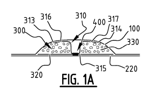
Figure 1A and 1B illustrate an exemplary embodiment of an absorbent article,
here a diaper. Figure
lA shows a cross-section of the absorbent article, and Figure 1B shows the
absorbent article in its
flat out, un-contracted state with the wearer side facing the viewer. The
skilled person understands
that the absorbent article may also be a pant or an adult incontinence garment
or the like. The
absorbent article comprising a liquid pervious topsheet 100, a liquid
impervious backsheet 200,
and an absorbent core 300 positioned between the liquid pervious topsheet 100
and the liquid
impervious backsheet 200. In a possible embodiment the absorbent article may
further comprise
adhesive between the absorbent core 300 and the liquid pervious topsheet 100.
The absorbent
article has a first and second longitudinal edge 103, 104 and a first and
second transverse edge 101,
102.
The absorbent core 300 comprises a top core sheet 310, a back core sheet 320,
and absorbent
material 330 arranged partially between the top core sheet 310 and the back
core sheet 320. The
top core sheet 310 comprises an attachment portion 315 which is attached to
the back core sheet
320 forming an attachment zone 400, and edge portions 316, 317 covering a
portion of the
absorbent material 330. Each edge portion 316, 317 has a free edge 313, 314,
and the free edges
313, 314 are not connected to the back core sheet 320. The first edge portion
316 and the second
edge portion 317 are located at opposite sides of the attachment portion 315.
In this manner the
first edge portion 316 and the second edge portion 317 provide a stable
structural basis for the
formation of a channel. When the absorbent core is wetted, the absorbent
material swells such that
the first edge portion 316 and the second edge portion 317 form embankments
delimiting the
channel for guiding the liquid. A portion of the absorbent material 330 is not
covered by the top
core sheet 310. In a possible embodiment the top core sheet 310 may be
attached to the liquid
pervious topsheet 100, e.g. using adhesive. The attachment zone 400 extends
from the crotch
region CR in the direction of the first and second transverse edge 101, 102.
Upon wetting of the
CA 03095521 2020-09-29
WO 2019/193103 PCT/EP2019/058524
absorbent material 330, a channel is created at said attachment zone 400. The
absorbent material
330 may swell upon wetting, and the edge portions 316, 317 may prevent the
absorbent material
330 from entering the attachment zone 400 and help with formation of
embankments delimiting the
channel upon wetting. This embodiment allows the amount of raw material for
manufacturing the
5 top core sheet 310 to be reduced, and as a result the manufacturing cost
can be reduced. Meanwhile
an absorbent article with good liquid distribution and absorption capacities
can still be obtained.
Seen in a top view of the absorbent core, the top core sheet 310 has a total
surface area of Si, the
back core sheet 320 has a total surface area of S2, the absorbent core 300 has
a surface area of SO
defined by an area covered by the absorbent material 330 plus an area of the
attachment zone 400.
10 51 is smaller than 90% of SO and/or S2 is smaller than 90% of SO,
preferably Si and/or S2 is
smaller than 80% of SO, more preferably Si and/or S2 is smaller than 70% of
SO, even more
preferably Si and/or S2 is smaller than 60% of SO, even more preferably Si
and/or S2 is smaller
than 50% of SO, most preferably Si and/or S2 is smaller than 40% of SO. In the
embodiment of
Figures 1 A and 1B, Si is approximately 60% of SO while S2 is substantially
the same as SO.
15 The attachment zone 400 has a center line CL, which is a straight line.
In other embodiments, the
center line CL may be a curve, or a polyline, or other shapes. The center line
is a line which is at
the same distance of opposite edges of the attachment zone 400, which
preferably extends in a
length direction of the attachment zone 400. The attachment zone 400 extends
from a crotch region
in the direction of the first and second transverse edge of the absorbent
article 101, 102, which
20 allows a better liquid distribution between crotch region and front/back
portion of absorbent article.
In other embodiments, the at least one attachment zone may extend in the
direction from the first
longitudinal edge 103 to the second longitudinal edge 104 of the absorbent
article, which allows a
better liquid distribution between left and right portions of absorbent
article. However, it is also
possible for the at least one attachment zone to extend under a small angle
with respect to the
25 longitudinal direction of absorbent core 300, e.g. an angle between 5
and 10 . Preferably the at
least one attachment zone is arranged symmetrically with respect to a
longitudinal center line of
absorbent core 300. A contour of the attachment zone 400 is adjacent to the
absorbent material,
which may comprises cellulosic fluff pulp and/or superabsorbent particles. A
length of the
attachment zone 400 is larger than 10% of the length of the absorbent core
300, more preferably
larger than 30%, even more preferably larger than 50%, which allows a better
liquid distribution
over a larger area of the absorbent core 300. The attachment zone 400 may be a
permanent
attachment zone which remains attached when wetted, allowing the channel to
distribute liquid
during consecutive liquid insults.
CA 03095521 2020-09-29
WO 2019/193103 PCT/EP2019/058524
26
The top core sheet 310 and the back core sheet 320 have a substantially
rectangular shape. The top
core sheet 310 has a longitudinal dimension which is substantially 100% of the
length of the
absorbent core 300 and a transverse dimension which is about 60% of the width
of the absorbent
core 300, while the longitudinal and transverse dimension of the back core
sheet 320 is
substantially the same as the length and width of the absorbent core 300,
respectively. In this
embodiment, a rear and front edge of the top core sheet 310 is attached to a
rear and front edge of
the back core sheet 320, respectively, providing a stable and integrated
structure of the absorbent
core 300 while the use of material can still be reduced.
In other embodiments, e.g. the embodiment of Figure 5A, a transverse dimension
of the top core
sheet 310 and/or a transverse dimension of the back core sheet 320 and the
width of the absorbent
core 300 may be within 10% difference, preferably substantially the same,
which allows an
attachment between the top core sheet 310 and the back core sheet 320 by the
longitudinal edges of
the absorbent core 300.
Preferably the attachment between top core sheet 310 and back core sheet 320
may be a permanent
attachment; and absorbent core 300 is configured such that, in a wetted state
of absorbent core 300,
the absorbent material 330 may extend partially over a bottom of the channel.
Alternatively, the
attachment between top core sheet 310 and back core sheet 320 may be a semi-
permanent
attachment configured to release after having been in contact with urine for a
predetermined period
of time, and the predetermined period of time is preferably smaller than 30 s.
The attachment zone 400 is provided by means of continuous attachments in the
longitudinal
direction of the absorbent core in Figure 1A and 1B. It is clear to the
skilled person that in a
possible embodiment the attachment zone may be provided by means of continuous
attachments in
the transversal direction of the absorbent core and/or discontinuous
attachments in the transversal
direction of the absorbent core and/or discontinuous attachments in the
longitudinal direction of the
absorbent core.
The channel created by the attachment zone 400 may be indicated with a color
and/or with a
pattern which is different from the color and/or pattern of topsheet. More in
particular the area of
the channel may comprise a print allowing a user to visually distinguish the
at least one channel.
This print may be arranged on the topsheet 100, on the top core sheet 310, on
the back core sheet
320, on the backsheet 200, or on any sheet in between the topsheet 100 and the
backsheet 200, as
long as it is visible for a user. As the sheets may be partially transparent,
the print may be arranged
on a sheet in between the topsheet 100 and the backsheet 200, as long as it is
visible through the
CA 03095521 2020-09-29
WO 2019/193103 PCT/EP2019/058524
27
topsheet 100 and/or the backsheet 200. Preferably the print is visible when
looking at the topsheet
100 of the diaper.
Figures 2A and 2B illustrate another exemplary embodiment of an absorbent
article which is
similar to the embodiment of Figures 1A and 1B, here a diaper. The absorbent
core 300 comprises
a top core sheet 310, a back core sheet 320, and absorbent material 330
arranged partially between
the top core sheet 310 and the back core sheet 320. The back core sheet 320
comprises an
attachment portion 325 which is attached to the back core sheet 320 forming an
attachment zone
400, and edge portions 326, 327 covering a portion of the absorbent material
330. Each edge
portion 326, 327 has a free edge 323, 324, and the free edges 323, 324 are not
connected to the top
core sheet 310. The first edge portion 326 and the second edge portion 327 are
located at opposite
sides of the attachment portion 325. A portion of the absorbent material 330
is not covered by the
back core sheet 320. Meanwhile an entire area of the absorbent material may be
covered by the top
core sheet 310. Thus, S2 is smaller than 60% of SO, and 51 is substantially
the same as SO. This
embodiment has the advantage that the amount of material used for
manufacturing the back core
.. sheet 320 can be reduced while at least one channel with good liquid
distribution and absorbent
capacities can still be created.
Figures 3A and 3B illustrate another exemplary embodiment of an absorbent
article, here a diaper.
The absorbent core 300 comprises a first top core sheet 310a, a second top
core sheet 310b, a first
back core sheet 320a, a second back core sheet 320b, and absorbent material
330 arranged partially
.. between the first top core sheet 310a and the first back core sheet 320a,
as well as between the
second top core sheet 310b and the second back core sheet 320b. The first top
core sheet 310a
comprises two attachment portions 315a, 315a' which are attached to the first
back core sheet 320a
forming two attachment zones 400a, 400a', and edge portions 316a, 317a
covering a portion of the
absorbent material. Each edge portion 316a, 317a has a free edge 313a, 314a,
and the free edges
313a, 314a are not connected to the first back core sheet 320a. Likewise, the
second top core sheet
310b comprises two attachment portions 315b, 315b' which is attached to the
second back core
sheet 320b forming two attachment zones 400b, 400b', and at least one second
edge portion 316b,
317b having at least one free edge 313b, 314b and covering a portion of the
absorbent material. In
this manner, multiple channels can be created with a further reduced amount of
material for
manufacturing both the top core sheets 310a, 310b and back core sheets 320a,
320b, as a result the
liquid distribution and absorption capacities of the absorbent core is further
improved with a lower
manufacturing cost. In addition, the quantity of liquid that can be
temporarily held in channels is
further increased, and the liquid can be more evenly distributed over the
entire absorbent core 300.
CA 03095521 2020-09-29
WO 2019/193103 PCT/EP2019/058524
28
A distance between the first top core sheet 310a and the second top core sheet
310b is at least 5%
of the width of the absorbent core 300, and/or a distance between the first
back core sheet 320a and
the second back core sheet 320b is at least 5% of the width of the absorbent
core 300. In this
manner a sufficient manufacturing cost reduction can be achieved.
Seen in a top view of the absorbent core 300, the first top core sheet 310a
has a total surface area of
Sla, the first back core sheet 320a has a total surface area of 52a, the
second top core sheet 310b
has a total surface area of Sib, the second back core sheet 320b has a total
surface area of 52b, the
absorbent core has a surface area of SO defined by an area covered by the
absorbent material plus
an area of the attachment zones. S la, Sib, 52a, 52b may be similar,
preferably substantially the
same, and Sla+S lb (and 52a+52b) is smaller than 60% of SO.
Figure 4A and 4B illustrate another exemplary embodiment of an absorbent
article, here a diaper.
According to the exemplary embodiment of Figure 4A and 4B, the top core sheet
310 comprises at
least one attachment portion 315 which is attached to the back core sheet 320
forming an
attachment zone 400, and edge portions 316, 317 having respective free edges
313, 314 and
covering a portion of the absorbent material 330. The attachment zone 400
comprises a first
attachment zone 401 and a second attachment branch 402 and a third attachment
branch 403. The
first and second attachment branches 401, 402 extend from the crotch region in
the direction of the
front transverse edge 101, and are interconnected to the third attachment
branch 403. The third
attachment branch 403 extends from the crotch region in the direction of the
rear transverse edge
102, respectively. The first attachment branch 401 and the second attachment
branch 402 form
together a substantially U-shaped zone. The U-shaped zone 401, 402 guides the
liquid from the left
and right parts of the front portion to the rear portion, or vice versa. In
that manner a convenient
liquid distribution channel network is created, allowing the liquid to be
distributed rapidly
throughout the absorbent core 300. In other embodiments the front and rear may
be reversed, i.e.
the branches 401, 402 may be in a rear portion of the absorbent article and
the third branch 403
may be in a front portion.
Figures 5A ¨ 13B illustrate exemplary embodiments of an absorbent core
comprising attachment
zones having different layouts, as well as edge portions having different
shapes. The principles
about the attachment zones set out below for various embodiments may also be
applied in other
described embodiments. In these embodiments, the absorbent core 300 at least
comprises a top
core sheet 310, a back core sheet 320, and absorbent material 330 arranged
partially between the
top core sheet 310 and the back core sheet 320. At least one of the top core
sheet 310 and the back
core sheet 320 comprises at least one attachment portion which is attached to
the other one of the
top core sheet 310 and the back core sheet 320 forming at least one attachment
zone 400, and at
CA 03095521 2020-09-29
WO 2019/193103 PCT/EP2019/058524
29
least one edge portion 316, 317 having at least one free edge 313, 314 and
covering a portion of the
absorbent material 330. Further, in alternative embodiments the top core sheet
and back core sheet
may be reversed, i.e. sheet 310 may be back core sheet and 320 may be a top
core sheet.
In the embodiment of Figure 5A, the attachment zone 400 extends in the
direction from the first
longitudinal edge to the second longitudinal edge of the absorbent article.
Upon wetting of the
absorbent material, one channel is created at said attachment zone 400, which
allows a better liquid
distribution between left and right portions of absorbent article. A
transverse dimension of the top
core sheet 310 and a transverse dimension of the back core sheet 320 and the
width of the
absorbent core 300 are within 10% difference, preferably substantially the
same. A transverse
dimension of the top core sheet 310 and a transverse dimension of the back
core sheet 320 and the
width of the absorbent core 300 are within 10% difference, preferably
substantially the same. A
longitudinal dimension of the top core sheet 310 is smaller than 40% of the
longitudinal dimension
of the back core sheet 320 and the length of the absorbent core 300. As a
result Si is smaller than
40% of S2 (and SO). The top core sheet 310 and the back core sheet 320 may be
attached at the
.. longitudinal edges of the absorbent core 300. The top core sheet 310
comprises an attachment
portion 315 and two edge portions 316, 317 having respective free edges 313,
314 extending in a
transverse direction on either side of the attachment portion 315.
The embodiment of Figure 5B is similar to the embodiment of Figure 5A, with
the difference that
the top core sheet 310 has a transverse dimension which is narrower than the
width of the
.. absorbent core 300 and the transverse dimension of the back core sheet 320.
In the embodiment of Figure 6A, the absorbent core 300 comprises a first top
core sheet 310a, a
second top core sheet 310b, a back core sheet 320, and absorbent material 330
arranged partially
between the first top core sheet 310a and the back core sheet 320, as well as
between the second
top core sheet 310b and the back core sheet 320. The first top core sheet 310a
comprises an
.. attachment portion which is attached to the back core sheet 320 forming a
first attachment zone
400a. Likewise, the second top core sheet 310b comprises an attachment portion
which is attached
to the back core sheet 320 forming one attachment zones 400b. The first
attachment zone 400a and
the second attachment zone 400b may extend in parallel in the longitudinal
direction of the
absorbent core 300, from the crotch region of the absorbent core to the front
and the rear transverse
edge of the absorbent core. Seen in a top view of the absorbent core 300, the
first top core sheet
310a has a total surface area of Sla, the second top core sheet 310b has a
total surface area of Sib,
the back core sheet 320 has a total surface area of S2, and the absorbent core
has a surface area of
SO. Sla and Sib are substantially the same, and S2 and SO are substantially
the same, and Sla+S lb
CA 03095521 2020-09-29
WO 2019/193103 PCT/EP2019/058524
is smaller than 40% of SO. The distance between the first top core sheet 310a
and the second top
core sheet 310b is at least 5% of the width of the absorbent core 300.
In the embodiment of Figure 6B, the at least one attachment portion comprises
a first attachment
zone 400a and a second attachment zone 400b. Both of the first attachment zone
400a and the
5 second attachment zone 400b may have a shape of a substantially straight
line. The first and
second attachment zones 400a, 400b extend in parallel from the crotch region
in the direction of
the front and the rear transverse edge of the absorbent article. The first and
second attachment
zones 400a, 400b may be connected through at least one semi-permanent
attachment zone 500,
preferably extending in a substantially transverse direction. In this manner
liquid can flow in a
10 transverse direction through the absorbent material of the absorbent
core. The back core sheet 320
and the absorbent core 300 have substantially the same longitudinal dimension
and transverse
dimension. The longitudinal and transverse dimension of the top core sheet 310
is smaller than the
longitudinal and transverse dimension of the back core sheet 320 (and the
absorbent core 300). 51
is smaller than 40% of S2 (and SO).
15 Figure 6C shows a similar embodiment as the embodiment of Figure 3B,
with the difference that
only one attachment zone 400a is formed between the first top core sheet 310a
and the first back
core sheet 320a, and only one attachment zone 400b is formed between the
second top core sheet
310b and the second back core sheet 320b. The attachment zones 400a, 400b
extend in parallel in
the longitudinal direction of the absorbent core 300, from the crotch region
of the absorbent core to
20 the front and the rear transverse edges of the absorbent core. The first
top core sheet 310a
comprises edge portions 316a, 317a covering a portion of the absorbent
material. Likewise, the
second top core sheet 310b comprises second edge portions 316b, 317b covering
a portion of the
absorbent material. The first back core sheet 320a comprises edge portions
326a, 327a covering a
portion of the absorbent material. Likewise, the second back core sheet 320b
comprises second
25 edge portions 326b, 327b covering a portion of the absorbent material.
Figure 6D shows a similar embodiment as the embodiment of Figure 6C. In this
embodiment, at
least one semi-permanent attachment zone 500a is further formed between the
first top core sheet
310a and the first back core sheet 320a. Likewise, at least one semi-permanent
attachment zone
500b is further formed between the second top core sheet 310a and the second
back core sheet
30 320a. The at least one semi-permanent attachment zones 500a, 500b extend
in a substantially
transverse direction of the absorbent core 300, and cross the first attachment
zone 400a and the
second attachment zone 400b, e.g. perpendicularly. In this manner liquid can
flow in a transverse
direction through the absorbent material of the absorbent core. The first top
core sheet 310a
comprises edge portions 316a, 317a covering a portion of the absorbent
material. Likewise, the
CA 03095521 2020-09-29
WO 2019/193103 PCT/EP2019/058524
31
second top core sheet 310b comprises second edge portions 316b, 317b covering
a portion of the
absorbent material. The first back core sheet 320a comprises edge portions
326a, 327a covering a
portion of the absorbent material. Likewise, the second back core sheet 320b
comprises second
edge portions 326b, 327b covering a portion of the absorbent material. It is
noted that the edge
portions 316a, 317a, 316b, 317b, 326a, 327a, 326b, 327b have respective free
edges in between the
semi-permanent attachment zones 500a, 500b.
In the embodiment of Figure 7, the absorbent core 300 comprises a first top
core sheet 310a, a
second top core sheet 310b, a back core sheet 320, and absorbent material 330
arranged partially
between the first top core sheet 310a and the back core sheet 320, as well as
between the second
top core sheet 310b and the back core sheet 320. The first top core sheet 310a
comprises an
attachment portion which is attached to the back core sheet 320 forming a
first attachment zone
400a. Likewise, the second top core sheet 310b comprises an attachment portion
which is attached
to the back core sheet 320 forming one attachment zones 400b. The first top
core sheet 310a
comprises edge portions 316a, 317a covering a portion of the absorbent
material. Likewise, the
second top core sheet 310b comprises second edge portions 316b, 317b covering
a portion of the
absorbent material. The first attachment zone 400a and the second attachment
zone 400b diverge
from the crotch region in the direction of a front and rear transverse edge of
absorbent core. The
center line of the first attachment zone 400a and the second attachment zone
400b may have a
curved shape. The first top core sheet 310a and the back core sheet 320 may
further be attached at
the transverse edges of the absorbent core 300, and likewise for the second
top core sheet 310b and
the back core sheet 320. Seen in a top view of the absorbent core 300, the
first top core sheet 310a
has a total surface area of Sla, the second top core sheet 310b has a total
surface area of Sib, the
back core sheet 320 has a total surface area of S2, and the absorbent core has
a surface area of SO.
Sla and Sib are substantially the same, and S2 and SO are substantially the
same, and Sla+S lb is
smaller than 60% of SO. The distance between the first top core sheet 310a and
the second top core
sheet 310b is at least 5% of the width of the absorbent core 300.
In the embodiment of Figure 8, a longitudinal dimension of the top core sheet
310 and a
longitudinal dimension of the back core sheet 320 and the length of the
absorbent core 300 are
within 10% difference, preferably substantially the same. A transverse
dimension of the top core
sheet 310 and a transverse dimension of the back core sheet 320 are
substantially the same, and are
smaller than 80% of the transverse dimension of the absorbent core 300. As a
result, Si and S2 are
substantially the same, and Si and S2 are smaller than 80% of SO. The top core
sheet 310 and the
back core sheet 320 may further be attached at the transverse edges of the
absorbent core 300. The
at least one attachment portion comprises an attachment zone 400, which
extends from the crotch
region in the direction of the front and the rear transverse edge, and has a
shape of substantially
CA 03095521 2020-09-29
WO 2019/193103 PCT/EP2019/058524
32
straight line. Semi-permanent attachment zones 500a, 500b are formed between
top core sheet 310
and back core sheet 320. As is illustrated, the front ends and rear ends and
mid-portions of the
semi-permanent attachment zones 500a, 500b and the attachment zone 400 may be
connected. The
semi-permanent attachment zones 500a, 500b together form a substantial "8"
shape, and the
attachment zone 400 is located on the center line of the "8" shape. In this
manner liquid can flow in
a both transverse and longitudinal direction through the absorbent material of
the absorbent core,
and liquid may be better distributed over the absorbent core.
In the embodiments of Figure 9A, 9B, 9C, a longitudinal dimension of the top
core sheet 310 and a
longitudinal dimension of the back core sheet 320 and the length of the
absorbent core 300 are
within 10% difference, preferably substantially the same. A transverse
dimension of the back core
sheet 320 and a transverse dimension of the absorbent core 300 are
substantially the same, and a
transverse dimension of the top core sheet 310 is smaller than 50% of the
transverse dimension of
the absorbent core 300 and the transverse dimension of the back core sheet
320. As a result, SO and
S2 are substantially the same, and 51 is smaller than 50% of SO and S2. The
top core sheet 310 and
the back core sheet 320 may further be attached at the transverse edges of the
absorbent core 300.
In the embodiment of Figure 9A, the at least one attachment portion comprises
a plurality of
attachment zones 400, 400', 400", 400'", which extend in a transverse
direction from the left
portion to the right portion of the absorbent core. The length of the
plurality of attachment zones
400, 400', 400", 400" ' in the transverse direction may be substantially the
same as the transverse
dimension of the top core sheet 310. The distance between each of the
plurality of attachment
zones 400, 400', 400", 400" ' is at least 5% of the longitudinal dimension of
the absorbent core
300, and may be equally divided. At either sides of the attachment zones 400,
400', 400", 400"
edge portions 316, 316', 317, 318, 318' are formed. Each edge portion 316,
316', 317, 318, 318'
has opposite free edges 313a, 314a; 313a', 314a'; 313b, 314b; 313c, 314c;
313c', 314c'.
In the embodiment of Figure 9B, the at least one attachment portion comprises
a plurality of
attachment zones, which comprises a first attachment zone 400 and a second
attachment zone 400'.
The first attachment zone 400 extends from the crotch portion of the absorbent
core 300 to one of
the front and rear transverse edge of the absorbent core 300, and the second
attachment zone 400'
extends from the crotch portion of the absorbent core to the other one of the
rear and front
transverse edge of the absorbent core.
In the embodiment of Figure 9C, the at least one attachment portion comprises
a plurality of
attachment zones 400, and each of the attachment zones may have a shape of
cross. The plurality
CA 03095521 2020-09-29
WO 2019/193103 PCT/EP2019/058524
33
of attachment zones 400 may be positioned in a row which extends in a
longitudinal direction of
the absorbent core.
In the embodiment of Figure 9D, the absorbent core 300 comprises a first back
core sheet 320a, a
second back core sheet 320b, a top core sheet 310, and absorbent material 330
arranged partially
between the first back core sheet 320a and the top core sheet 310, as well as
between the second
back core sheet 320b and the top core sheet 310. The first back core sheet
320a comprises an
attachment portion which is attached to the top core sheet 310 forming a first
attachment zone
400a. Likewise, the second back core sheet 320b comprises one attachment
portion which is
attached to the top core sheet 310 forming a second attachment zones 400b. The
first attachment
zone 400a and the second attachment zone 400b comprises a plurality of
discrete attachments such
as dots which have preferably substantially no absorbent material between the
top core sheet 310
and the first back core sheet 320a, and between the top core sheet 310 and the
second back core
sheet 320b. Meanwhile absorbent material is present in an area in-between said
plurality of mini
attachment zones, between the top core sheet 310 and the first back core sheet
320a, and/or
between the top core sheet 310 and the second back core sheet 320b. The first
attachment zone
400a and/or the second attachment zone 400b may be formed by discontinuous
attachments
arranged according to a pattern extending in the longitudinal direction of the
absorbent core 300.
Figure 10 shows a similar embodiment as the embodiment of Figure 6A, with the
difference that a
third attachment zone 400c is further formed. The first attachment zone 400a
and the second
attachment zone 400b may extend in parallel in the longitudinal direction of
the absorbent core 300,
from the crotch region of the absorbent core 300 to the front (or the rear)
transverse edge of the
absorbent core. And the third attachment zone 400c may extend in the
longitudinal direction of the
absorbent core, from the crotch region of the absorbent core to the rear (or
the front) transverse
edge of the absorbent core.
In the embodiments of Figures 6A, 6C, 6D, 7, 9D, 10, the absorbent core 300
further comprises a
second top core sheet 310b and/or a second back core sheet 320b, and at least
one second
attachment zone is further formed. It is possible that the absorbent article
further comprising a
second top core sheet 310b and a second back core sheet 320b (e.g. Figures 6C,
6D). The second
top core sheet 310b comprises at least one second attachment portion which is
attached to the
second back core sheet 320b forming at least one second attachment zone 400b,
and at least one
second edge portion 316b, 317b having at least one free edge and covering a
portion of the
absorbent material. It is also possible that the absorbent article further
comprising a second top
core sheet 310b comprising at least one second attachment portion which is
attached to the back
core sheet 320 forming at least one second attachment zone 400b, and at least
one second edge
CA 03095521 2020-09-29
WO 2019/193103 PCT/EP2019/058524
34
portion 316b, 317b having at least one free edge and covering a portion of the
absorbent material
(e.g. Figures 6A, 7, 10). It is also possible that the absorbent article
further comprises a second
back core sheet 320b, said second back core sheet comprising at least one
second attachment
portion which is attached to the top core sheet 310 forming at least one
second attachment zone
400b, and at least one second edge portion 326b, 327b having at least one free
edge and covering a
portion of the absorbent material (e.g. Figure 9D). A distance between the top
core sheet and the
second top core sheet is at least 5% of the width of the absorbent core,
and/or a distance between
the back core sheet and the second back core sheet is at least 5% of the width
of the absorbent core.
In the embodiment of Figure 11, the back core sheet 320 and the absorbent core
300 have
substantially the same longitudinal dimension and transverse dimension. The
longitudinal and
transverse dimension of the back core sheet 320 is smaller than the
longitudinal and transverse
dimension of the back core sheet 310 (and the absorbent core 300). S2 may be
smaller than 60% of
Si (and SO). The at least one attachment portion comprises a first attachment
zone 400a, a second
attachment zone 400b, a third attachment zone 400c and a fourth attachment
zone 400d, and a
central attachment zone 400e in the crotch region. The first and second
attachment zones 400a,
400b diverge from the central attachment zone 400e in the direction of a rear
(or front) transverse
edge of absorbent core. The third and fourth attachment zone 400c, 400d
diverge from the central
attachment zone 400e in the crotch region in the direction of a front (or
rear) transverse edge of
absorbent core. The first attachment zone 400a and the second attachment zone
400b form together
a substantially V-shaped zone. Similarly, the third attachment zone 400c and
the fourth attachment
zone 400d form together a substantially V-shaped zone. The V-shaped zones
guide the liquid from
left and right parts of the front and/or the rear portion. The V-shaped zones
at the front and rear
portion of the absorbent core are connected by a central longitudinal
attachment zone 400e, and a
convenient liquid distribution channel network is created allowing the liquid
to be distributed
rapidly throughout the absorbent core 300.
In the embodiment of Figure 12, a longitudinal dimension of the top core sheet
310 and a
longitudinal dimension of the back core sheet 320 and the length of the
absorbent core 300 are
within 10% difference, preferably substantially the same. A transverse
dimension of the back core
sheet 320 and a transverse dimension of the absorbent core 300 are
substantially the same, and a
transverse dimension of the top core sheet 310 is smaller than 70% of the
transverse dimension of
the absorbent core 300 and the transverse dimension of the back core sheet
320. As a result, SO and
S2 are substantially the same, and Si is smaller than 70% of SO and S2. The
top core sheet 310 and
the back core sheet 320 may further be attached at the transverse edges of the
absorbent core 300.
The at least one attachment portion comprises at least one attachment zone
400, which comprises a
first attachment zone 400a and a second attachment zone 400b. The first
attachment zone 400a
CA 03095521 2020-09-29
WO 2019/193103 PCT/EP2019/058524
crosses the second attachment zone 400b at a crossing point. The first and
second attachment zones
400a, 400b together form a substantially X-shaped zone. Preferably the
crossing point is on a
longitudinal center line of the absorbent core 300 extending between the
transverse edges.
Preferably the crossing point is in the crotch portion of the absorbent core
300.
5 In the embodiment of Figure 13A and 13B, a longitudinal dimension of the
top core sheet 310 and
a longitudinal dimension of the back core sheet 320 and the length of the
absorbent core 300 are
within 10% difference, preferably substantially the same. A transverse
dimension of the top core
sheet 310 and a transverse dimension of the absorbent core 300 are
substantially the same, and a
transverse dimension of the back core sheet 320 is smaller than 70% of the
transverse dimension of
10 the absorbent core 300 and the transverse dimension of the top core
sheet 310. As a result, SO and
Si are substantially the same, and S2 is smaller than 70% of SO and 51. The
top core sheet 310 and
the back core sheet 320 may further be attached at the transverse edges of the
absorbent core 300.
In the embodiment of Figure 13A, the at least one attachment portion comprises
an attachment
zone 400, which comprises a first attachment zone 400a and a second attachment
zone 400b and a
15 third attachment zone 400c and a fourth attachment zone 400d. The first
attachment zone 400a and
the second attachment zone 400b may extend in parallel in a longitudinal
direction of the absorbent
core, and the third attachment zone 400c and the fourth attachment zone 400d
may extend in
parallel in a transverse direction of the absorbent core. The front (or rear)
ends of the first
attachment zone 400a and the second attachment zone 400b may be connected by
the third
20 attachment zone 400c, preferably by the left and right ends of the third
attachment zone 400c,
respectively. The rear (or front) ends of the first attachment zone 400a and
the second attachment
zone 400b may be connected by the fourth attachment zone 400d, preferably by
the left and right
ends of the fourth attachment zone 400d, respectively. The first, second,
third and fourth
attachment zones 400a, 400b, 400c, 400d, together form an enclosed region with
a substantially
25 rectangular shape. Edge portions 316, 317 with free edges extend on
either side of the attachment
zones 400a, 400b.
In the embodiment of Figure 13B, the at least one attachment portion comprises
an attachment
zone 400 which comprises a first attachment zone 401 and a second attachment
zone 402, which
are interconnected by a third attachment zone 403 in a front or rear portion
of the absorbent core
30 300. In that manner any leakage via the front or rear portion can be
reduced or avoided. In the
embodiment of figure 13B the first attachment zone 401, the second attachment
zone 402 and the
third attachment zone 403 form together a substantially U-shaped zone. This
substantially U-
shaped zone comprises a first elongate attachment zone 401 (indicated as a
solid fill area), a second
elongate attachment zone 402 (indicated as a solid fill area), and a third
attachment zone 403
CA 03095521 2020-09-29
WO 2019/193103 PCT/EP2019/058524
36
(indicated as a hatched area). The first and second elongate attachment zone
401, 402 extend next
to each other from the crotch region in the direction of the front transverse
edge and in the
direction of the rear transverse edge. The third attachment zone 403 connects
said first elongate
attachment zone 401 with said second attachment zone 402. The third attachment
zone 403 may be
a rear connecting attachment zone which connects a rear end portion of the
first attachment zone
401 to a corresponding rear end portion of the second attachment zone 402. The
U-shaped zone
401, 402, 403 guides the liquid from the left and right parts of the front
portion to the rear portion.
As illustrated the third attachment zone 403 may be arranged in the rear
portion. In that manner a
convenient liquid distribution channel network is created allowing the liquid
to be distributed
rapidly throughout the absorbent core.
Figure 14 illustrates another exemplary embodiment of an absorbent article.
The absorbent article
further comprises an acquisition and distribution layer ADL 350 positioned
between the absorbent
core 300 and the liquid pervious topsheet 100. This serves to slow down the
flow so that the liquid
has adequate time to be absorbed by and evenly distributed over the absorbent
core. The absorbent
article may further comprise adhesive 360 between the absorbent core 300 and
the ADL 350,
and/or the absorbent article comprises adhesive 360 between the ADL and the
liquid pervious
topsheet 100.
Figure 15A and 15B illustrates an exemplary embodiment of an apparatus and a
method for
manufacturing an absorbent article according to an embodiment similar to the
embodiment of
Figure 2A and 2B but without the semi-permanent attachment zone. The method
comprises:
¨ preparing an absorbent core by providing a top core sheet 310 and a
back core sheet 320,
and by arranging absorbent material 330 partially between the top core sheet
310 and the back core
sheet 320. The top core sheet 310 is attached to the back core sheet 320
forming two attachment
zones, and the attaching is such that at least one of the top core sheet 310
and the back core sheet
320 has at least one edge portion having at least one free edge and covering a
portion of the
absorbent material; and
¨ including the absorbent core between a liquid pervious topsheet 100
and a liquid
impervious backsheet 200.
The method may be carried out in detailed according to the steps described
below.
In the embodiment of Figures 15A and 15B, the method comprises in a first step
guiding a first
sheet material, e.g. the top core sheet 310, along an optional guide roller 5,
and further along a
rotating member 10, wherein a surface of said rotating member 10 is provided
with a pattern with
CA 03095521 2020-09-29
WO 2019/193103 PCT/EP2019/058524
37
suction zones 13 and non-suction zones 11. It is noted that a portion of the
pattern of suction zones
13 and non-suction zones 11 is normally covered by the top core sheet 310, but
for clarity purposes
the top core sheet 310 is shown in a transparent manner to reveal the suction
and non-suction zones
11, 13 of the rotating member 10. The suction zones 13 may be provided with
holes, and the non-
suction zones 11 are formed of closed material. For example, the non-suction
zones 11 may be
provided with inserts. The inserts may have a trapezoidal cross section. The
inserts may be fixed
e.g. with screws on the rotating member 10. At an inner area of the rotating
member 10 a vacuum
is applied, see VACUUM 1. The non-suction zones 11 may comprise at least one
elongate zone 11
extending in a circumferential direction of the rotating member 10 in order to
form at least one
elongate attachment portion 400a, 400b. In the illustrated example a plurality
of pairs of adjacent
elongate non-suction zones are provided in order to form two elongate
attachment portions 400a,
400b in each absorbent core. In this step, a top core sheet 310 is provided.
In a second step an absorbent material 330 is applied via a hopper 40 on said
top core sheet 310 on
the rotating member 10. As a result, at least one attachment portion of the
top core sheet 310
located above the non-suction zones 11 and remaining portions of the top core
sheet 310 located
above the suction zones 13 are covered with the absorbent material 330,
wherein the absorbent
material 330 is sucked towards the suction zones 13. However, some absorbent
material 330 may
remain on the non-suction zones 11.
Optionally, in a third step, the absorbent material 330 remaining on the at
least one non-suction
zone 11 may be locally removed, such that substantially no absorbent material
330 is present on
the at least one attachment portion. The local removal of the absorbent
material 330 may be done
by a mechanical and/or pneumatic means. The removed absorbent material 330 may
be discarded
and/or collected and/or recycled by a further discharge means, such that the
removed absorbent
material can be further used. The discharge means preferably comprises a
vacuum source to collect
the removed absorbent material.
In a fourth step a second sheet material, e.g. the back core sheet 320 is
applied on top of the
absorbent material 330 on the top core sheet 310, e.g. using a further
rotating member 15. In the
this step, a back core sheet 320 is provided, such that absorbent material 330
is arranged partially
between the top core sheet 310 and the back core sheet 320.
In a fifth step a third sheet material, e.g. the liquid impervious backsheet
200, is applied on top of
the back core sheet 320, e.g. using a further rotating member 20. In this
step, the liquid impervious
backsheet 200 is provided.
In a sixth step the top core sheet 310 is attached to the back core sheet 320
at least in the at least
one attachment portions, and such that two attachment zones are formed. The
attaching may be
done by applying pressure and/or heat on the top core sheet material 310
and/or on the back core
CA 03095521 2020-09-29
WO 2019/193103 PCT/EP2019/058524
38
sheet material 320 in the at least one attachment portion, e.g. by a rotating
member 30 and/or
opposite rotating member 30' which is provided with at least a first and a
second seal rib 31, 32
dimensioned for applying pressure and/or heat on the top core sheet material
310 in the at least one
attachment portion in order to create the two attachment zones. Additionally
or alternatively
.. adhesive may be applied to the back and/or top core sheets 310, 320, to
release the bond between
the top and back core sheets. In this step, two attachment zones 400a, 400b
are formed by attaching
the top core sheet 310 to the back core sheet 320, and the attaching is such
that the top core sheet
310 has two edge portions each having a free edge and covering a portion of
the absorbent material
330. The skilled person understands that this step may also be carried out
before both the backsheet
200 and the topsheet 100 are provided or after both the backsheet 200 and the
topsheet 100 are
provided.
In a seventh step a fourth sheet material, e.g. the liquid pervious topsheet
100 is applied on top of
the top core sheet 310, e.g. using a further rotating member 25. An adhesive
360 may be applied
between the absorbent core and the liquid pervious topsheet 100. In this step,
the absorbent core is
included between a liquid pervious topsheet 100 and a liquid impervious
backsheet 200.
In a possible embodiment, an acquisition and distribution layer ADL, is
included between the
absorbent core 300 and the liquid pervious topsheet 100. This serves to slow
down the flow so that
the liquid has adequate time to be absorbed by and evenly distributed over the
absorbent core.
In a possible embodiment, adhesive is applied between the absorbent core 300
and the ADL,
and/or between the ADL and the liquid pervious topsheet 100.
The top core sheet 310 and/or the back core sheet 320 can be any suitable
material web which has
sufficient strength to process through the apparatus, and preferably
economically, environmentally
and usage sensible. The top core sheet 310 and/or the back core sheet 320 may
comprise a paper or
fibrous tissue, woven or non-woven fabric, a cellulose web or batt, airlaid or
wet laid structure or
the like. Alternatively, the top core sheet 310 and/or the back core sheet 320
is a porous, gas
permeable web material such as a porous film or fibrous web.
The top core sheet 310 and/or the back core sheet 320 may also be an
essentially endless web
material in the longitudinal direction. One preferred web material is a so
called SMS material,
comprising a spunbonded, a melt-blown and a further spunbonded layer. Highly
preferred are
permanently hydrophilic non-wovens, and in particular nonwovens with durably
hydrophilic
coatings. An alternative preferred material comprises a SMMS-structure.
Another preferred web
material is a nonwoven containing cellulosic fibers, paper or tissue sheet or
other airlaid, drylaid or
wetlaid material, as these products greatly improve the wicking capacity of
the product. The top
core sheet 310 and/or the back core sheet 320 may be provided from two or more
separate sheets of
CA 03095521 2020-09-29
WO 2019/193103 PCT/EP2019/058524
39
materials or they may be alternatively provided from a unitary sheet of
material. Preferred non-
woven materials are provided from synthetic fibers, such as PE, PET and most
preferably PP. As
the polymers used for non-woven production are inherently hydrophobic, they
are preferably
coated with hydrophilic coatings.
The backsheet 200 prevents the bodily exudates absorbed by the absorbent core
300 and contained
within the diaper from soiling other external articles that may contact the
wearer, such as bed
sheets and undergarments. In preferred embodiments, the backsheet 200 is
substantially
impervious to bodily exudates and comprises a laminate of a nonwoven and a
thin plastic film such
as a thermoplastic film. The backsheet 200 may comprise breathable materials
that permit vapour
to escape from the diaper while still preventing bodily exudates from passing
through the
backsheet 200. It may be semi-rigid, non-elastic and can be made fully or
partially elasticized and
include backing. The backsheet 200 may be assembled in a variety of well-known
configurations
and are well known in the art.
The topsheet 100 is preferably soft, compliant, exhibits good strikethroughs
and has a reduced
tendency to rewet from the liquid absorbent material. The topsheet 100 is
placed in close proximity
to the skin of the wearer when the diaper is worn. In this way, such topsheet
100 permits bodily
exudates to rapidly penetrate it, so as to flow toward the absorbent core 300
more quickly, but
preferably not allowing such bodily exudates to flow back through the topsheet
100. The topsheet
100 may be constructed from any one of a wide range of liquid and vapour
permeable, preferably
hydrophilic, materials. The upper and lower surface of the topsheet 100 may be
treated differently
and may for instance include a surfactant on the upper surface so as to
facilitate liquid transfer
there through, especially at a central zone or area of the topsheet 100
located over the absorbent
core 300, and for instance include a hydrophobic agent on the lower surface to
minimize the liquid
contained within the absorbent core from contact wetting the topsheet 100
thereby reducing rewet
values. The topsheet 100 may also be coated with a substance having rash
preventing or rash
reducing properties (e.g. aloe vera). The topsheet 100 covers substantially
the entire wearer facing
area of the diaper, including substantially all of the front waist region,
back waist region, and
crotch region. Further, the side panels and/or waist feature layers of the
inner region may be
formed from the same single top sheet material and, thus, may be referred to
as being unitary with
the topsheet 100 in forming longitudinal and lateral extensions of the
topsheet material.
Alternatively, the topsheet 100 may be formed from multiple different
materials which vary across
the width of the topsheet 100. Such a multiple piece design allows for
creation of preferred
properties and different zones of the topsheet 100. The topsheet 100 be semi-
rigid, non-elastic and
can be made fully or partially elasticized. The topsheet 100 may be assembled
in a variety of well-
known configurations and are well known in the art.
CA 03095521 2020-09-29
WO 2019/193103 PCT/EP2019/058524
Figure 16A, 16B, 16C illustrate schematically exemplary embodiments of methods
for
manufacturing an absorbent article. The top core sheet 310 and the back core
sheet 320 may be fed
continuously in a transport direction in the form of a web top core material
and a web back core
material having a first width w 1, w 1 a and a second width w2, w2a, seen in a
direction
5 .. perpendicular on the transport direction, respectively; wherein the
absorbent material 330 is
arranged such that, seen in a direction perpendicular on the transport
direction, a distance between
outer limits of absorbent material is wO, wherein the distance w0 is larger
than the first and/or the
second width, preferably at least 10% larger, more preferably at least 20%
larger, even more
preferably at least 40% larger.
10 Figure 16A illustrates schematically an exemplary embodiment of method
for manufacturing an
absorbent article. The top core sheet 310 and the back core sheet 320 are fed
continuously in a
transport direction in the form of a web top core material and a web back core
material having a
first width w 1, and a second width w2, seen in a direction perpendicular on
the transport direction,
respectively. The absorbent material 330 is arranged such that, seen in a
direction perpendicular on
15 the transport direction, a distance between outer limits of absorbent
material 330 is wO. The
distance w0 is larger than the first width w 1, preferably at least 10%
larger, more preferably at
least 20% larger, even more preferably at least 40% larger. In this particular
embodiment, the
distance w0 is at least 40% larger than the first width wl, the distance w0
and the second width w2
are within 10% difference, preferably substantially the same.
20 The attaching may be such that a first edge portion 316 and a second
edge portion 317 located at
opposite sides of the attachment portion 315, having at least one free edge
313, 314 and covering a
portion of the absorbent material, are formed. The first edge portion 316 and
a second edge portion
317 may have a substantially similar width w3, and w3 is at least 1% of wO,
preferably more than
3% of wO, even more preferably more than 5% of wO. This provides a stable
structural basis for the
25 formation of channel after the absorbent core is wetted, and results in
the formation of tubes which
provide a tub shape to the absorbent core. In the attachment zone 400
substantially no absorbent
material is arranged between the top core sheet 310 and the back core sheet
320. The attachment
zone 400 may be a continuous zone, which allows a better liquid distribution
throughout the entire
channel of the absorbent core 330, enabling better liquid absorbance. However,
also a pattern of
30 discrete attachments (e.g. dots, crosses, squares, etc.) may be used to
form the attachment zone
400. In that regard it is noted that when the distance between the discrete
attachments is small, e.g.
lower than 1 cm or lower than 0.5 cm, a more or less continuous channel can be
obtained upon
wetting
CA 03095521 2020-09-29
WO 2019/193103 PCT/EP2019/058524
41
A rear and front edge of the top core sheet 310 may be attached to a rear and
front edge of the back
core sheet 320, respectively, which provides a more stable structure of the
absorbent core while the
use of material can still be reduced.
Figure 16B illustrates schematically another exemplary embodiment of method
for manufacturing
an absorbent article. In this embodiment, the distance w0 is at least 40%
larger than the second
width w2, the distance w0 and the first width w 1 are within 10% difference,
preferably
substantially the same. The attaching may be such that the at least one
attachment zone comprises a
first attachment zone 400a and a second attachment zone 400b, which allows the
creation of at
least two channels using the at least one of the top core sheet 310 and the
back core sheet 320. In
this manner the quantity of liquid that can be temporarily held is further
increased. In addition, as
the total area of the attachment increases accordingly, the liquid can be more
evenly distributed
over the entire absorbent core. The first edge portion 326 and a second edge
portion 327 may have
a substantially similar width w3, and w3 is at least 1% of wO, preferably more
than 3% of wO, even
more preferably more than 5% of wO.
The attaching may be such that the first attachment zone 400a and the second
attachment zone
400b extend next to each other from the crotch region in the direction of the
first and/or the second
transverse edge of the absorbent article, which allows a better liquid
distribution between crotch
region and front and/or back portion of absorbent article.
The attaching may be such that the first attachment zone 400a and the second
attachment zone
400b are connected through at least one semi-permanent attachment zone,
preferably extending in
a substantially transverse direction, so that liquid can flow in a transverse
direction through the
absorbent material 330 of the absorbent core 300.
Figure 16C illustrates schematically another exemplary embodiment of method
for manufacturing
an absorbent article, according to the embodiment of Figure 6C. The method
comprises providing a
first top core sheet 310a, a first back core sheet 320a, a second top core
sheet 310b and a second
back core sheet 320b, and arranging absorbent material 330 partially between
the first top core
sheet 310a and the first back core sheet 320a, as well as between the second
top core sheet 310b
and the second back core sheet 320b. The first top core sheet 310a is attached
to the first back core
sheet 320a forming at a first attachment zone 400a, and the attaching is such
that the first top core
sheet 310a has two second edge portion 316a, 317a having at least one free
edge 313a, 314a and
covering a portion of the absorbent material. The second top core sheet 310b
is attached to the
second back core sheet 320b forming at a second attachment zone 400b, and the
attaching is such
that the second top core sheet 310b has two second edge portion 316b, 317b
having at least one
CA 03095521 2020-09-29
WO 2019/193103 PCT/EP2019/058524
42
free edge 313b, 314b and covering a portion of the absorbent material. In this
manner, two
channels can be created with a reduced amount of material for manufacturing
both the top core
sheet and back core sheet, as a result the liquid distribution and absorption
capacities of the
absorbent core is further improved with a reduced manufacturing cost. The
first width w 1 a and the
second width w2a of the first top core sheet 310a and the first back core
sheet 320a, respectively,
are within 10% difference, preferably substantially the same. And the first
width w lb and the
second width w2b of the second top core sheet 310b and the second back core
sheet 320b,
respectively, are within 10% difference, preferably substantially the same.
The distance w0 is
larger than the sum of wla + w lb (= w2a + w2b). The edge portions 316a, 317a,
316b, 317b may
have a substantially similar width w3, and w3 is at least 1% of wO, preferably
more than 3% of wO,
even more preferably more than 5% of wO.
In addition, the providing is preferably such that a distance dl between the
first top core sheet 310a
and the second top core sheet 310b is at least 5% of the width of the
absorbent core wO, and/or a
distance d2 between the back core sheet 320a and the second back core sheet
320b is at least 5% of
the width of the absorbent core wO. In this manner a sufficient manufacturing
cost reduction can be
achieved.
Figures 17A and 17B illustrate another exemplary embodiment of an absorbent
article comprising
a liquid pervious topsheet 100, a liquid impervious backsheet 200, and an
absorbent core 300
positioned between the liquid pervious topsheet 100 and the liquid impervious
backsheet 200. The
absorbent article has a first and second longitudinal edge 103, 104 and a
first and second transverse
edge 101, 102. The absorbent core 300 comprises a top core sheet 310, a back
core sheet 320, and
a layer of absorbent material 330 arranged partially between the top core
sheet 310 and the back
core sheet 320, such that the top core sheet 310 and the back core sheet 320
do not fully wrap the
absorbent material. The top core sheet 310 comprises at least one attachment
portion which is
attached to the back core sheet 320 forming an attachment zone 400, and at
least two edge portions
316, 317 covering a portion of the layer of absorbent material 330 on either
side of the attachment
zone 400. The edge portions 316, 317 each have an edge adjacent the attachment
zone 400 and an
opposite edge 313, 314 attached to the back core sheet 320, see attachment
zones 600a, 600b
which may be covered by absorbent material 330. Preferably the top sheet 100
is attached, e.g.
using adhesive, to the absorbent material 330 on either side of the top core
sheet 310 and/or to the
top core sheet 310. By providing the top core sheet 310 such that it covers
only a portion of a layer
of absorbent material, the top core sheet 310 does not cover the entire top
surface of the absorbent
material 330, resulting in less raw material needed for the absorbent core
300. The attachment zone
400 is capable of creating a channel for liquid distribution and absorption
upon wetting. In this
manner, a channel can be created with a reduced amount of material used for
manufacturing the
CA 03095521 2020-09-29
WO 2019/193103 PCT/EP2019/058524
43
top core sheet 310, and as a result the manufacturing cost can be reduced
while good liquid
distribution and absorption capacities can be maintained.
In the illustrated example of figures 17A and 17B, the top core sheet 310 has
a reduced width.
However in other embodiments the back core sheet 320 may have a reduced width,
or both 310,
320 may have a reduced width as has been illustrated above for embodiments
with free edges.
Preferably, seen in a top view of the absorbent core, the top core sheet 310
has a total surface area
of Si, the back core sheet 320 has a total surface area of S2, the absorbent
core 300 has a surface
area of SO defined by an area covered by the absorbent material plus an area
of the at least one
attachment zone, wherein Si is smaller than 90% of SO and/or S2 is smaller
than 90% of SO. Si
.. and/or S2 may be smaller than 80% of SO, preferably Si and/or S2 may be
smaller than 70% of SO,
more preferably Si and/or S2 may be smaller than 60% of SO, even more
preferably Si and/or S2
may be smaller than 50% of SO, most preferably Si and/or S2 may be smaller
than 40% of SO.
Preferably, in the at least one attachment portion 400 substantially no
absorbent material is present
between the top core sheet and the back core sheet. In the attachment zones
600a, 600b, absorbent
material may be present.
The skilled person understands that the principles of the method illustrated
in figures 15A, 15B,
16A and 16B may also be used to produce an absorbent core as illustrated in
figures 17A and 17B,
wherein additional attachment means may be provided to connect the edges 313,
314.
Although not illustrated in the figures, it is noted that one or more further
discrete attachment
zones, e.g. dot shaped attachment zones, may be provided, e.g. in a number of
points along the free
edges of the top and/or back core sheet to ensure that the top and back core
sheet remain in a
correct position with respect to each other. For example, in the embodiment of
figures 17A and
17B instead of providing the elongate attachment zones 600a, 600b there may be
provided a
plurality of discrete smaller attachment zones along the edges 313, 314, or in
the corners of the top
core sheet 310.
Whilst the principles of the invention have been set out above in connection
with specific
embodiments, it is to be understood that this description is merely made by
way of example and
not as a limitation of the scope of protection which is determined by the
appended claims.