Note: Descriptions are shown in the official language in which they were submitted.
SENSOR
Field
This disclosure relates to sensors, membranes for use in the sensors, methods
for
making such sensors and membranes and methods for detecting or determining the
quantity of glucose in a sample.
Background
Molecular receptors such as boronates can be used in sensors for the detection
and/or
measurement of analyte in biological fluids. For example, a sensor may
comprise a
glucose receptor (the boronic acid) and a fluorophore that acts as the
transmitter of
the signal. These indicator chemistries can readily be immobilised onto an
optical
fibre of appropriate diameter, which can then be placed into body fluids or
tissue to
measure analytes such as glucose.
Summary
Under oxidative stress, it has been found that levels of reactive oxygen
species
(ROS) such as hydrogen peroxide (H202) can rise. Oxidative stress can arise as
a
result of an ischemic event or sepsis (e.g. as a result of multi-organ
failure) and is
also implicated in many diseases (e.g. atherosclerosis, Parkinson's disease,
heart
failure, myocardial infarction, Alzheimer's disease, schizophrenia, bipolar
disorder,
fragile X syndrome and chronic fatigue syndrome), thereby raising levels of
ROS in
1
Date Recue/Date Received 2022-03-16
the body fluids or tissue of subjects who may require their glucose levels to
be
monitored, for example in an intensive care environment. ROS in the blood
could
therefore interfere with sensor indicating chemistry.
It has been found that including a ROS-quenching agent in the sensor could
eliminate
or ameliorate the interferent effect on sensor chemistry of ROS in the blood.
Accordingly, a sensor for detecting and/or quantifying the amount of analyte
in a
sample can include:
-a sensing region; and
-a barrier layer including a reactive oxygen species (ROS)-quenching,
analyte-permeable membrane having an ROS-quenching agent adsorbed
thereto;
wherein the sensor is adapted so that the sample enters the sensing region of
the
sensor through said barrier layer.
The presence of ROS-quenching agents in sensors can oxidise (or otherwise
deplete)
analyte, which can adversely affect the sensor operation. For example, glucose
may
be oxidised to gluconic acid. The sensor can thus include a means to address
the
problem of analyte oxidation in sensors including a ROS-quenching agent. In
some
embodiments, therefore, the membrane of the sensor can selectively quench ROS
over analyte.
In some embodiments, the sensor includes a reactive oxygen species (ROS)-
quenching, analyte-permeable membrane, suitable for use in a sensor for
detecting
and/or quantifying the amount of analyte in a sample, the membrane having an
ROS-
quenching activity sufficient to quench a solution of H202 having a
concentration of
100ppm or less.
2
Date Recue/Date Received 2020-10-09
A process for producing a ROS-quenching analyte-permeable membrane suitable
for
use in a sensor for detecting and/or quantifying the amount of analyte in a
sample is
also described. The process includes:
(iii) contacting a barrier layer with a ROS-quenching precursor and a
reducing
agent;
(iv) reducing the ROS-quenching precursor to form a ROS-quenching agent
on or in the barrier layer; and
optionally repeating steps (iii) and (iv).
A membrane obtainable or obtained by this process is also described.
In one embodiment the process further comprises, before step (iii):
(i) contacting a barrier layer with a ROS-quenching precursor and a
preliminary reducing agent;
(ii) partially reducing the ROS-quenching precursor to form a ROS-
quenching agent on or in the barrier layer; and
optionally repeating steps (i) to (iv). Thus, in this embodiment, the process
includes:
(i) contacting a barrier layer with a ROS-quenching precursor and a first
reducing agent;
(ii) partially reducing the ROS-quenching precursor to form a ROS-
quenching agent on or in the barrier layer;
(iii) contacting the barrier layer with a second reducing agent;
(iv) fully reducing the remaining ROS-quenching precursor to form a ROS-
quenching agent on or in the barrier layer; and
optionally repeating steps (i) to (iv). A membrane obtainable or obtained by
this
process is also described.
The process described herein is particularly beneficial in that it achieves
deposition
of the ROS-quenching agent within the pores of a membrane, rather than merely
on
the surface of the membrane. Such deposition within the pores can be achieved
even
3
Date Recue/Date Received 2020-10-09
where the membrane has a high aspect ratio, for example an aspect ratio of at
least
100, typically at least 150 or 200. Deposition of the ROS-quenching agent
within the
pores leads to an improved ability of the membrane to quench ROS, since fluid
passing through the membrane will be in contact with an ROS-quenching agent
throughout the time it is moving through the pores.
A method of detecting and/or quantifying the amount of analyte in a sample is
also
described. The method can include inserting into the sample a sensor as
described
herein, providing incident light to the sensing region of the sensor, and
detecting the
emission pattern of the fluorophore.
Further preferred features and embodiments are described in the accompanying
description.
Brief description of the Figures
Figures la and lb depict a sensor incorporating an optical fibre and a monitor
for
such a sensor.
Figures 2, 3a and 3b depict various embodiments of a sensing region of a
sensor.
Figure 4 depicts a schematic version of an apparatus which may be used to
determine
ROS quenching ability and/or analyte depletion for a membrane.
Figures 5a-d depicts SEM images for the membrane of Example 2.
Figure 6 depicts the results of in vitro testing of a sensor and a
corresponding sensor
without a platinised membrane.
Figure 7 depicts the results of Example 4.
4
Date Recue/Date Received 2020-10-09
Figure 8 depicts a schematic view of the process for producing a ROS-quenching
barrier layer
Figures 9a and 9b depict the results of in vivo testing of a sensor provided
herein (Figure 9b)
and a corresponding sensor without a platinised membrane in Figure 9b.
Figure 10 depicts the results of Example 9. Results for the three platinised
sensors
are shown as IB070-001, TB070-002, and TB070-003. Results for the unplatinised
control are shown as TB066-011.
Detailed description
As used herein an ROS-quenching, analyte-permeable barrier layer is a material
which allows the passage of analyte through the layer but which restricts or
preferably prevents ROS from passing through the layer, typically by
catalysing its
decomposition into chemical species which do not interfere with sensor
chemistry
(e.g. boronic acid/flurophore chemistry).
The ROS-quenching, analyte-permeable barrier layer is envisaged for use with
any
sensor. In some embodiments, the sensor is a glucose sensor, preferably an
optical
glucose sensor using boronic acid/fluorophore glucose sensing chemistry. The
sensor can also be an electrochemical or pH sensor.
The ROS-quenching, analyte-permeable barrier layer may be used with any
optical
sensor having an optical waveguide for directing incident light onto the
sensing
region of the sensor. For example, the optical sensor can be a fibre optic
sensor.
Glucose sensing can be carried out in bodily fluids such as interstitial
tissue or blood,
although sensing of any aqueous solution may be carried out using the sensors
5
Date Recue/Date Received 2020-10-09
described herein. The particular embodiments described herein are envisaged
for use
as invasive sensors for insertion into a blood vessel. However, the use of the
ROS-
quenching, analyte-permeable barrier layer is not limited to such invasive
sensors.
Non-invasive sensors for in vitro use, implantable sensors, and subcutaneous
sensors
can also include a ROS-quenching, analyte-permeable barrier layer.
As used herein, the words "include" and "contain", and variations thereof such
as
"includes", "contains", "including" and "containing", are used in an inclusive
sense,
i.e. to specify the presence of the stated features but not to preclude the
presence or
addition of further features.
The Barrier Layer
The barrier layer comprises an ROS-quenching, analyte-permeable membrane
having
an ROS-quenching agent adsorbed thereto. The ROS-quenching agent may be
adsorbed to the surface of the membrane (e.g., the membrane is coated with the
ROS-quenching agent), or may be adsorbed to the pores of the membrane (e.g.,
the
membrane may be impregnated with the ROS-quenching agent).
Suitable analyte-permeable membranes which can be coated or impregnated with
an
ROS-quenching agent and used as the barrier layer in the sensor include semi-
permeable membranes such as dialysis membranes and microporous hollow fibre
membranes.
In some embodiments, the barrier layer is hydrophilic.
Dialysis membranes are semi-permeable membranes that separate molecules by
virtue of their size, shape, hydration and polarity. Dialysis membranes are
usually in
the form of hollow fibres and are available in materials such as
polyarylethersulphone, polyamide, polycarbonate, polyacrylonitrile,
polysulphone,
6
Date Recue/Date Received 2020-10-09
polyethersulphone, polyvinylidenefluoride and cellulosic materials or mixtures
or
modifications thereof.
Microporous hollow fibre membranes are known in the art and include
polypropylene hollow fibre membranes. For example, a polypropylene hollow
fibre
membrane having a pore size of from 0.1 to 0.2[im, with a porous area of
approximately 40% of the surface, a minimum internal diameter of the fibre of
416iiim and a maximum outer diameter of the fibre of 510iiim can be coated or
impregnated with an ROS-quenching agent and used as the barrier layer.
In one aspect of this embodiment, a polymer, e.g. a hydrophilic and/or
negatively
charged polymer, is present within the pores of the membrane. This can be
achieved
via in situ polymerisation, within the pores of the membrane, of a monomer
mixture,
for example including one or more hydrophilic monomers and/or one or more
negatively charged monomers. Suitable in situ polymerisation techniques are
described in international patent application number PCT/GB2011/000209.
In other embodiments, the membrane does not have a hydrophilic polymer present
within its pores.
In some embodiments, the membrane used to form the barrier layer in the sensor
is a
dialysis membrane or a polypropylene hollow fibre membrane.
A semi-permeable membrane used in the barrier layer typically has a pore size
of
from 1 nm to 1 micron, e.g. from 1 to 20 nm or from 0.1 to 0.5 micron.
Typically the
hollow fibre polypropylene membrane used to form the barrier layer of the
present
sensor will have pore dimensions of from 0.1 micron to 0.5 micron, e.g. 0.1 to
0.3
micron such as about 0.2 micron. The dialysis membrane used to form the
barrier
7
Date Recue/Date Received 2020-10-09
layer of the present sensor will typically have pore dimensions of 100
nanometers or
less. Preferred pore sizes are 1 to 20nm, preferably 1 to lOnm, for example
about
6nm.
In some embodiments, the membrane has an aspect ratio of at least 100,
preferably at
least 150, for example at least 200 or at least 250. As used herein, the
aspect ratio is
the ratio of the length of each pore (i.e. the thickness of the membrane)
divided by
the pore diameter. Advantageously, the ROS-quenching agent is distributed
along the
length of the pore (i.e. not only at the opening of the pore or a part of the
pore
adjacent the opening of the pore). The techniques for producing the ROS-
quenching
membrane described are particularly effective at facilitating distribution of
the ROS-
quenching agent along the length of the pore. The thickness of the membrane is
typically at least about 20 micron, for example at least about 30 micron. The
thickness may be up to about 50 micron, for example up to about 40 micron.
Typically in this embodiment the membrane is a hollow fibre polypropylene
membrane.
Semi-permeable membranes are available with different pore sizes relating to
the
molecular weight cut-off (MWCO) of the membrane. The molecular weight cut-off
indicates the maximum molecular weight of molecule which can pass through the
pores of the membrane. The semi permeable membrane used in the present sensor
has a MWCO such that the analyte can pass through. The semi permeable membrane
used in the present sensor is typically a low MWCO material that does not
allow
materials of molecular weight 6,000 or higher (e.g. to proteins) to pass
through, but
does allow glucose (MW180) to pass. Preferred membranes have a MWCO of at
least 1,000 and preferably no more than 5,000. For example, the MWCO may be at
least 1,500 or at least 2,000, for example no more than 4,000.
8
Date Recue/Date Received 2020-10-09
The effective pore size and MWCO of the final barrier layer used in the sensor
(herein "effective pore size", "effective MWCO") may be lower than those
described
above as a result of in situ polymerisation, or loading of the ROS quenching
agent.
The effect of in situ polymerisation on pore size is described in
PCT/GB2011/000209 (referenced above).
Preferred effective pore sizes for the final membrane are at least mm,
e.g. at least 2nm or at least 4nm and no more than 20nm, e.g. no more than
lOnm.
Preferred effective MWCO are at least 1,500 or at least 2,000 and no more than
6,000 e.g. no more than 5,000 preferably no more than 4,000.
Measurement of the pore size, or effective pore size, can be carried out by
any
method known to the skilled person. Typically, the pore size is given as the
median
pore size for any particular membrane. MWCO can be determined by the diffusion
of monodisperse materials of known molecular weights with a fluorescent
molecule
attached. Materials of gradually increasing molecular weight are passed
through the
membrane and the diffusion breakthrough can be determined using a fluorimeter
as a
detector. Examples of suitable monodisperse materials are fluorescein-labelled
dextrans available from Sigma-Aldrich in a variety of molecular weights. The
effective pore size or effective MWCO may be measured by preparing the final
membrane and measuring the pore size or MWCO in the usual way.
In order to provide an acceptable response time (for instance for an
intravascular
sensor which continuously measures glucose), the barrier layer should
preferably be
selected so as to provide a 90% response time of a sensor which is no more
than
three minutes, preferably no more than two-and-a-half minutes.
The 90% response time is determined as the time taken from addition of a known
amount of analyte to a sample, to the sensor response reaching 90% of the
analyte
concentration. This can be measured by contacting the sensor with a zero
analyte
9
Date Recue/Date Received 2020-10-09
aqueous solution, adding a known amount of analyte at time to and monitoring
the
sensor response over time. The sensor response increases over time and the
time after
to at which the sensor reading corresponds to 90% of the added analyte
concentration
is taken as the 90% response time. In this technique, the analyte is added in
such a
manner that the change in concentration of the aqueous solution is
substantially
instantaneous, so there is no time delay due to, for example, dissolution of
the
analyte. Thus, analyte is typically added in liquid or concentrated solution
form,
with stirring.
ROS Quenching Agent
The ROS-quenching agent used in the barrier layer can be any substance capable
of
catalysing the decomposition of reactive oxygen species such as H202.
The decomposition of H202 into chemical species which do not interfere with
sensor
chemistry (e.g. boronic acid/flurophore chemistry) can occur by
disproportionation to
water and oxygen gas:
2H202 ¨> 2H20 + 02
Suitable substances capable of catalysing the decomposition of ROS such as
H202
include transition metals, transition metal compounds and enzymes.
Typically, the transition metal used as the ROS-quenching agent is a metal of
Group
10 or 11 of the Periodic Table, e.g. nickel, palladium, platinum, copper,
silver or
gold. Preferably, the transition metal used as the ROS-quenching agent is
palladium,
platinum, gold or silver. More preferably, the transition metal used as the
ROS-
quenching agent is platinum. An alloy of two or more metals, such as an alloy
of a
transition metal of Group 10 or 11 with another metal, or an alloy of two or
more
Date Recue/Date Received 2020-10-09
Group 10 or 11 transition metals, may also be used. Alloys of gold and silver
are
particularly envisaged.
Typically, the transition metal compound used as the ROS-quenching agent is a
compound of a metal of Group 7 of the Periodic Table, e.g. a Group 7 oxide,
for
instance manganese dioxide.
Typically, the enzyme used as the ROS-quenching agent is catalase or
superoxide
dismutase, preferably catalase.
In a preferred embodiment, the ROS-quenching agent is a metal of Group 10 or
11 of
the Periodic Table or an alloy containing such a metal. In a particularly
preferred
embodiment, the ROS-quenching agent is a metal of Group 10 or an alloy
containing
such a metal, more preferably platinum or a gold/silver alloy, most preferably
platinum. These metals are particularly useful as the ROS-quenching agent as
they
have an extremely long lifetime in a device and degradation is not of concern.
The
metals can also be simply adsorbed to the membrane (either to the surface or
preferably within the pores). Immobilisation, for example by covalent
attachment of
the quenching agent is not required.
When the ROS-quenching agent is a transition metal or a transition metal
compound,
it is typically present in the membrane in the form of nanoparticles, i.e.
particles with
a nanoscale average particle size, typically 1-100 nm, for example at least
5nm,
lOnm or at least 20nm, and for example up to 90nm, 80nm or 70nm.
Nanoparticulate
materials are advantageous since they can be provided within the pores of the
membrane rather than solely on the surface. Their small size also facilitates
an even
distribution of the particles through the membrane pores, leading to improved
efficiency in quenching ROS.
11
Date Recue/Date Received 2020-10-09
In the case of nanoparticles, the particles may have any appropriate form or
crystal
structure. For example, platinum nanoparticles may be in the form of
tetrahedron,
cube, octahedron, truncated cube, cuboctahedron, truncated octahedron,
triangular
plate, bipyramid, tripod, decahedron, rod or wire or icosahedron. Platinum
nanoparticles may also be produced as spherical particles, hollow structures
and
dendrites. The various structures and techniques for their preparation are set
out in
Zhenmeng Peng, Hong Yang, Nano Today, 2009, 4, 143-164.
Brief details of the preparation of these different forms are set out in Table
1
below:
Table 1: Pt Nanoparticles Crystal Structures.
Precursor Reductante Surfactantb Additivec Conditiond
Shapee
K2PtC14 H2 Na[PA] pH RT, 12 h C, T
K2PtC14 H2 Acrylic acid pH RT, 12 h C, T
K2PtC14 H2 PNIPA LCST C
K2PtC14 H2 PNEA LOST Tri
K2PtC14 H2 PVP, PNIPA, RT Tri, Sq,
Na[PA] Hex
K2PtC16 H2 Na[PA] RT C, TO
K2PtC16 H2 PVP 25-45 C T
H2PtC16, H2 PVP RT, T
K2PtC14. overnight
K2PtC14 H2 Na3[Cit] NaOH RT C, T, Hex
H2PtC16 H2 PVP RT, Tri, SF
overnight
K2PtC16 H2 PVP RT Tet
Na2IptC14 PVP PVP 80 C Tri, SP
K2PtC16 Na3[Cit] Na[PA] Reflux, 3.5 SP
h
K2PtC16 NaBH4, Hz, TTAB 50 C C, CO,
AA PP
H2PtC16 NaBH4 CTAB AgNO3 RT C
K2PtC16 NaBH4 CTAB HCI RT, 12 h DD
H2PtC16 Et0H PNIPA Reflux SP
H2PtC16 NaBH4, Hz Pluronic L64 RT SP
H2PtC16 NaBH4 MSA SP
K2[Pt(C204)2] H2 K2C204, CaCl2 RT or 55 C C, Hex
K2PtC14.
K2PtC16
K2PtC14. Cu foil Cu2+ C
Na2IptC16 Vitamin B2 Vitamin B2 RT SP
H2PtC16 Hydrazine AOT Isooctane RT SP
K2PtC14. y-ray CTAB Hexanol RT NR
H2PtC16 Hydrazine Berol 050 Isooctane RT SP
12
Date Recue/Date Received 2022-03-16
K2PtC14 UV, AA SDS, Brij-35, SnOEP, SP
DSPC chol
K2PtC14 AgNR C/S
H2PtC16 CoN P 95 C Hol
H2PtC16 H2 Et-HMM 200 C for 4 Nec
H2PtC16 ED RT SP
K2PtC14 ED AA H2SO4 RT TH H
K2PtC16 ED H2SO4 RT NH
Na2PtC16 ED HCI RT NW
K2PtC16 ED H3B03 RT NT
H2PtC16 y-ray Me0H RT SP
H2PtC16 UV Me0H RT NW
PtC14 Microwave a-Glucose SP
Table 1.
aPVP = poly(N-vinyl-2-pyrrolidone); Na3[Cit] = sodium citrate; AA = ascorbic
acid;
Et0H = ethanol; NR = nanorod; NP = nanoparticle; ED = electrodeposition.
bNalPA] = sodium polyacrylate; PNIPA = poly(N-isopropylacrylamide); PNEA =
poly(N-ethylacrylamide); TTAB = tetradecyltrimethylammonium bromide; CTAB =
hexadecyltrimethylammonium bromide; Pluronic L64 = E013P030E013 triblock
copolymer; MSA = me rcap tosuccinic acid; AOT = sodium bis (2-
ethylhexyl)sulfosuccinate; SDS = sodium dodecylsulfate; DSPC=1,2-distearoyl-
snglycero- 3-phosphocholine.
`Me0H = methanol; SnOEP=Sn(IV) octaethylporphyrin; chol = cholesterol.
dLCST = lower critical solution temperature; RT = room temperature.
eC = cube; T = tetrahedron; 0= octahedron; THH = tetrahexahedron; CO =
cuboctahedron; TO= truncated octahedron; SP = spherical particle; Tri =
triangle; Sq
= square; Tet = tetragon; Hex = hexagon; NR = nanorod; NW= nanowire; NT =
nanotube; Nec = necklace-structure; C/S = core/shell structure; SF = snowflake-
like
particles; DD = dendrite; PP = porous particles; NH = nanohorn; Hol = hollow
structure.
Preferred forms for platinum nanoparticles include cubic, cuboctahedron,
dendrite
and spherical particles.
Typically, when the ROS-quenching agent is a transition metal or a transition
metal
compound it present at a loading of 0.01 to 5 wt% of the membrane, preferably
0.1 to
5 wt%, more preferably 0.5 to 3wt %. The loading can be calculated from the
density
of the ROS-quenching agent, the uncoated/unimpregnated membrane, and the
coated/impregnated membrane.
13
Date Recue/Date Received 2020-10-09
In some embodiments, the ROS quenching agent is present on the surface of the
membrane. In alternative embodiments, the ROS quenching agent is present
within
the pores of the membrane.
ROS-quenching activity
In some embodiments the membrane used in the ROS-quenching barrier layer has
an
ROS-quenching activity sufficient to quench a solution of H202 having a
concentration of lOppm, i.e. it can quench a solution having a H202
concentration of
at least lOppm. The membrane typically has an ROS-quenching activity
sufficient to
quench a solution of H202 having a concentration of 20ppm, preferably 50ppm
and
more preferably 70ppm, 80ppm or 100ppm.
H202 concentrations are typically measured to an accuracy of +/- 2 to 5ppm.
Accordingly, as used herein, where an H202 concentration is indicated this is
assumed to be stated to an accuracy of +/-5ppm. A 400ppm H202 solution is
prepared by diluting a 30% hydrogen peroxide solution (133 ill) in UHP water
(100m1). This 400ppm solution is diluted to obtain the required concentration.
Thus,
a lOppm solution is obtained by diluting lml of the 400ppm solution in 39m1 of
UHP
water. Similarly, a 100ppm solution is obtained by diluting 10m1 of the 400ppm
solution in 30m1UHP water.
ROS-quenching activity can be determined by passing up to 100 1 (e.g. 100 1)
of a
solution of H202 having a known concentration (e.g. lOppm, prepared as set out
above) through a hollow fibre membrane (fibre: inner diameter approx 410 lam;
outer
diameter approx 500 lam, typical length 25mm), e.g. using a needle, as
schematically
represented in Figure 4, and measuring the H202 concentration of the solution
once
passed through the membrane. The solution is said to be quenched if the
concentration of H202 in the solution once passed through the membrane is less
than
about 0.5 ppm. When measuring H202 concentration using standard reagent strips
14
Date Recue/Date Received 2020-10-09
known in the art, the detection limit is approximately 0.5 ppm, so that if
detection is
carried out using such a standard reagent strip, a quenched solution will have
a
concentration of H202 which is undetectable.
Oxidation of analyte
The ROS-quenching membrane is typically capable of catalysing the
decomposition
of ROS without substantially oxidising (or otherwise depleting) analyte (e.g
glucose). Thus, preferred ROS quenching agents selectively oxidise ROS, such
as
H202, over analyte. In some embodiments therefore, the membrane selectively
quenches ROS. As used herein, a membrane which selectively quenches ROS
typically has an ROS quenching activity sufficient to quench a solution having
an
H202 concentration of at least 10 ppm, and substantially does not deplete
analyte
(e.g. it has an analyte depletion rate of 1 mmol/hour or less, preferably 0.05
mmol/hour or less and/or it depletes analyte by no more than 80%, preferably
no
more than 95% when analyte is passed through the membrane).
The extent of analyte depletion can be determined by passing a solution of
analyte
(e.g. 100 to 500 1) having a known concentration through a wall of a membrane
(fibre: inner diameter approx 410 lam; outer diameter approx 500 lam, 0.5mm,
typical
length 25mm), e.g. using a needle, as schematically represented in Figure 4,
and
measuring the analyte concentration of the solution once passed through the
membrane. A membrane which substantially does not deplete analyte will
typically
produce a concentration of analyte in the solution once passed through the
membrane
of 80% or more of that of the original solution, typically 85% or more,
preferably
90% or more, more preferably 95% or more, most preferably 99% or more.
Alternatively, the rate of depletion can be determined by placing the membrane
in a
solution of analyte having a known concentration and determining the analyte
concentration at regular intervals. Typically, the analyte concentration is
determined
Date Recue/Date Received 2020-10-09
regularly (e.g. every 8 hours) over a period of at least 24 hours, preferably
at least 48
hours. A typical procedure is set out in Example 3, for determining glucose
depletion. A membrane which substantially does not cause depletion of analyte
typically provides a rate of depletion of no more than 0.1 mmol analyte per
hour,
preferably no more than 0.08 mmol/hour, more preferably no more than 0.05
mmol/hour.
In some embodiments the extent or rate of analyte depletion is controlled by
selecting an appropriate ROS-quenching agent, as described above.
In another embodiment the extent or rate of analyte depletion is controlled by
selecting an appropriate ROS-quenching activity, as described above.
In another embodiment the extent or rate of analyte depletion is controlled by
selecting an appropriate method for producing the ROS-quenching agent, as
described below.
In another embodiment, the extent or rate of analyte depletion is controlled
by
selecting an appropriate form of nanoparticle, and/or by selecting an
appropriate
nanoparticle size, as described above.
The Sensor
An example of a sensor incorporating an optical fibre is depicted in Figures
la and
lb. The sensor 1 comprises an optical fibre 2 including a sensing region 3 at
its
distal end. In the case of an invasive sensor, fibre 2 is adapted for
insertion into a
patient, for example insertion into a blood vessel through a cannula. The
sensing
region 3 (depicted in more detail in Figures 2 and 3a) contains a cell or
chamber 7 in
which the indicator chemistry is contained. The optical fibre extends through
cable 4
to connector 5 which is adapted to mate with an appropriate monitor 8. The
monitor
16
Date Recue/Date Received 2020-10-09
typically includes further optical cable 4a that mates with the connector at
5a and at
the other end bifurcates to connect to (a) an appropriate source of incident
light for
the optical sensor 9 and (b) a detector for the return signal 10.
In some embodiments, the sensor is a disposable sensor. The sensor is
typically
adapted to be connected to a non-disposable monitor including a light source 9
and
detector 10.
As depicted in Figure 2, the sensing region 3 incorporates a cell 7 in the
form of a
chamber within the fibre. The cell may take any form, as long as it enables
the
indicator chemistry to be contained in the path of the incident light directed
by the
waveguide, here a fibre. Thus, the cell may be attached to the distal end of
the fibre
or waveguide or may be in the form of a chamber within the fibre having any
desired
shape.
The cell 7 contains the indicator chemistry. In the case of a glucose sensor,
this is
typically a boronic acid receptor for binding glucose and a fluorophore
associated
with the receptor. The emission pattern (e.g. the wavelength, intensity,
lifetime) of
the fluorophore is altered when the analyte is bound to the receptor allowing
optical
detection of glucose. The description of the sensor will be given in detail
herein with
regard to a glucose sensor. However, it is to be appreciated that the ROS-
quenching,
analyte-permeable barrier layer can be applied to sensors other than glucose
sensors.
Sensors having design features in addition to or different from those shown in
the
attached Figures are of course possible, provided that these include both of
the
required sensing region and barrier layer. For example, sensors such as those
described and illustrated in W02008/141241, W02008/098087 and
W02011/113020 can be used.
17
Date Recue/Date Received 2020-10-09
The receptor and fluorophore may be directly bonded to one another as a
receptor-
fluorophore construct. Examples of suitable fluorophores are described in WO
2010/116142, and include
anthracene, pyrene and derivatives thereof. Examples of suitable boronic acid
receptors are compounds having at least one, preferably two boronic acid
groups.
In a preferred embodiment, the receptor is a group of formula (I)
B (OH )2
LJ (I)
B(OH )2
(CH2)m
N ¨Sp ¨NI ¨(CH 2)n
L2 Li
wherein m and n are the same or different and are typically one or two,
preferably
one; Sp is an alphatic spacer, typically an alkylene moiety, for example a Cl-
C12
alkylene moiety, e.g. a C6 alkylene moiety; and Ll and L2 represent possible
points
of attachment to other moieties, for example to a fluorophore or to a
hydrogel. For
example, Ll and L2 may represent an alkylene, alkylene-arylene or alkylene-
arylene-alkylene moiety, linked to a functional group. Where no attachment to
another moiety is envisaged, the functional group is protected or replaced by
a
hydrogen atom. Typical alkylene groups for Ll and L2 are Cl-C4 alkylene
groups,
e.g. methylene and ethylene. Typical arylene groups are phenylene groups. The
functional group is typically any group which can react to form a bond with,
for
example, the fluorophore or hydrogel, e.g. ester, amide, aldehyde or azide.
18
Date Recue/Date Received 2020-10-09
Varying the length of the spacer Sp alters the selectivity of the receptor.
Typically, a
C6-alkylene chain provides a receptor which has good selectivity for glucose.
Further details of such receptors are found in US 6,387,672 -
Further examples of receptors suitable for the sensor include those of formula
(II):
OH OH
1 1
0 B.OH HO-B 0
(II)
--X. ,
N N1
,(CHRi)i, (CI-IRi)n;
wherein X represents 0, S, NR2 or CHR3;
n is from 1 to 4;
m is from 1 to 4, and n+m is 5;
R2 represents hydrogen or C1-4 alkyl;
each Ri is the same or different and represents hydrogen, C14 alkyl or C3-7
cycloalkyl;
or Ri, together with an adjacent Ri, R2 or R3 group and the carbon or nitrogen
atoms
to which they are attached, form a C3-7 cycloalkyl or a 5- or 6-membered
heterocyclyl group,
wherein when X represents CHR3, R3 together with an adjacent Ri group and the
carbon atoms to which they are attached form a C3-7 cycloalkyl group. Further
details of receptors of this type are found in US 61/431,756.
As used herein the term alkyl or alkylene is a linear or branched alkyl group
or
moiety. An alkylene moiety may, for example, be one in which from 1 to 15
carbon
19
Date Recue/Date Received 2020-10-09
atoms are present such as a C1_12 alkylene moiety, C1-6 alkylene moiety or a
C1-4
alkylene moiety, e.g. methylene, ethylene, n-propylene, i-propylene, n-
butylene,
butylene and t-butylene. C1-4 alkyl is typically methyl, ethyl, n-propyl, i-
propyl, n-
butyl or t-butyl. For the avoidance of doubt, where two alkyl groups or
alkylene
moieties are present, the alkyl groups or alkylene moieties may be the same or
different.
An alkyl group or alkylene moiety may be unsubstituted or substituted, for
example
it may carry one, two or three substituents selected from halogen, hydroxyl,
amine,
(C1_4 alkyl) amine, di(C1-4 alkyl) amine and C1-4 alkoxy. Preferably an alkyl
group or
alkylene moiety is unsubstituted.
As used herein an arylene group is an unsaturated group which may be
monocyclic,
bicyclic, or in which three or four fused rings may be present. Typically, an
arylene
group is phenylene. Arylene groups may be unsubstituted or substituted.
Suitable
substituents are C1-4 alkyl groups, for example methyl and ethyl. Preferably,
an
arylene group is unsubstituted.
As used herein a C3-7 cycloalkyl group is typically a cyclopentyl or
cyclohexyl
group. C3-7 cycloalkyl groups may be unsubstituted or substituted. Suitable
substituents are C1_4 alkyl groups, for example methyl and ethyl. Preferably,
a C3-7
cycloalkyl group is unsubstituted.
As used herein a 5- or 6-membered heterocyclyl group is a 5- or 6-membered
saturated ring in which one or more, typically one or two, e.g. one,
heteroatom
selected from N, 0 and S is present. Preferred heterocyclyl groups are those
in
which a nitrogen atom is present, for example piperidinyl and pyrrolidinyl.
Heterocyclyl groups may be unsubstituted or substituted. Suitable substituents
are
Date Recue/Date Received 2020-10-09
C1-4 alkyl groups, for example methyl and ethyl. Preferably, a heterocyclyl
group is
unsubstituted.
The receptor and fluorophore are typically bound to one another and may
further be
bound to a polymeric matrix such as a hydrogel, or to a dendrimer. Examples of
suitable hydrogels and dendrimers are those described in PCT/GB2011/000207 .
Alternatively, the first receptor and first fluorophore may be not directly
bonded to
one another (for example, they may be not bonded to one another or they may be
bonded only via a polymeric chain such as a polymeric chain contained within a
hydrogel matrix). It will be clear that when the first receptor and first
fluorophore
are not directly bonded to one another, they must still be capable of
interacting in
such a way that the fluorescence behaviour of the first fluorophore changes
when the
indicator system is exposed to glucose. For example, the first fluorophore and
the
second fluorophore may be capable of binding electrostatically (e.g., as a
charge
pair), which binding is capable of being at least partly disrupted by the
presence of
glucose. Examples of suitable first fluorophores include pyranine (HPTS) and
its
derivatives, such as HPTS itself and the derivatives HPTS-PEG, HPTS-MA, HPTS-
CO2, HPTS-TriCys-MA and HPTS-LysMA disclosed in US 2009/0177143.
Further suitable
first fluorophores may include the SNAF and SNAFL dyes commercially available
from Molecular Probes. Examples of suitable first receptors include aromatic
boronic acids covalently bonded to a conjugated nitrogen-containing
heterocyclic
aromatic bis-onium structure (e.g. a viologen). Examples of such first
receptors are
provided in US 2009/0177143.
One particularly suitable first receptor is 3,3'-oBBV, as
described in US 2009/0177143.
21
Date Recue/Date Received 2022-03-16
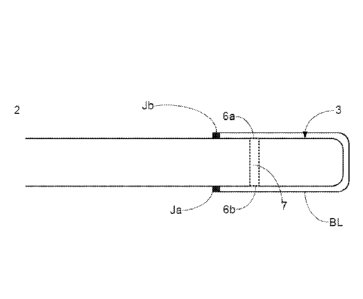
The sensing region 3 of the glucose sensor has one or more openings 6a, 6b to
enable
glucose to enter the cell. The barrier layer can be provided across these
openings so
that the sample under test enters the cell through the barrier layer. In
Figures 2 and
3a, the barrier layer is provided over the entire sensing region 3.
Alternatively,
however, the barrier layer may be provided on only part of the sensing region,
for
example only across openings 6a and 6b.
The sensor is typically designed such that any openings into the sensing
region
through which the sample under test can pass are covered with the barrier
layer. This
ensures that passage of H202 into the sensing region is restricted or
prevented. In
some embodiments, the entire sensing region, or the entire surface of the
sensor
which is to come into contact with the sample under test, is coated or
sheathed with
the barrier layer.
As depicted in Figure 2, the barrier layer BL may be applied directly onto the
sensing
region, here onto the tip of the optical fibre. This embodiment is
appropriate, for
example, where the barrier layer is a dialysis membrane. In an alternative
embodiment depicted in Figure 3a, the sensing region 3 is provided on a
separate
support 11. The separate support structure can provide additional strength
compared
with the application of the barrier layer directly to the sensing region, and
this
embodiment is therefore also appropriate for use with dialysis membrane
barrier
layers. Holes or pores are provided in the support to enable glucose to enter
the
sensing region 3. Suitable support structures are polymer tubes which are
perforated
with holes, for example by laser ablation. Microporous hollow fibres which are
commonly used in medical oxygenators and which have pores of approximately 0.2
micron in diameter provide appropriate support structures for use with fibre
optic
sensors. Alternative support structures are woven sheaths of polymeric or
metallic
materials such as those described in W02009/019470
22
Date Recue/Date Received 2020-10-09
In some embodiments, as depicted in Figure 3b, the barrier layer itself may
form the
support structure (BL/11). Preferably, in this embodiment, the membrane used
to
form the barrier layer is a microporous hollow fibre membrane.
If desired, the barrier layer may be adhered to the surface of the sensor e.g.
to the
optical fibre itself, or, where relevant, to the separate support structure.
This can be
achieved by application of a suitable adherent such as cyanoacrylate.
Alternatively,
where the sensor surface and the barrier layer material are appropriate, the
joint
between the barrier layer and the sensor can be thermoformed, e.g. at Ja, Jb
of
Figures 2 and 3a.
Method of Manufacture
The sensor is manufactured by providing a sensing region including suitable
indicating chemistry (e.g. in the case of a glucose sensor a boronic acid
receptor for
binding to glucose and a fluorophore associated with said receptor);
and providing an ROS-quenching analyte-permeable barrier layer on at least a
part of
the sensing region; and wherein the sensor is adapted so that analyte enters
the
sensing region of the sensor through said barrier layer. In the case of an
optical
sensor the method of manufacture also includes providing an optical waveguide
fro
directing incident light onto the sensor.
In some embodiments, the membrane used in the ROS-quenching analyte permeable
barrier layer is formed by vapour deposition. In this embodiment, the ROS-
quenching agent is typically a metal or an alloy and the metal or alloy is
sputtered
under vacuum and at low temperature to form a metal vapour which can be
directed
toward the membrane for deposition on the membrane surfaces, including those
within the pores of the membrane structure.
23
Date Recue/Date Received 2020-10-09
In an alternative embodiment, the membrane used in the ROS-quenching analyte
permeable barrier layer is formed by a method including (i) coating or
impregnating
a semi-permeable membrane, as described above, with an ROS-quenching agent,
(ii)
washing the membrane and (iii) drying the membrane.
In some embodiments, step (i) comprises wetting a membrane in a suitable water
miscible solvent followed by shaking. In a preferred example of this
embodiment,
the solvent is capable of solvating the pores of the membrane. In some
examples of
this embodiment the solvent is a polar non-protic solvent. In some examples of
this
embodiment the solvent is hydrophobic but water soluble. Specific examples of
solvents capable of solvating the pores of the membrane include N-
methylpyrrolidone (NMP), dimethylsulfoxide (DMSO) and dimethylformamide
(DMF). Wetting a membrane with a solvent capable of solvating the pores of the
membrane is particularly effective in enabling the ROS quenching agent to be
distributed along the length of the pores.
In some embodiments, step (i) comprises immersing a membrane in a solution
containing a species capable of forming an ROS-quenching agent (an ROS-
quenching precursor) and subsequently subjecting the membrane to conditions
such
that the H202-quenching agent forms on or in the membrane. In a preferred
example
of this embodiment, when the H202-quenching agent is platinum, step (i)
comprises
soaking the membrane in a solution of a platinum containing salt, such as a
tetra- or
hexa-chloroplatinate salt e.g. sodium or potassium tetrachloroplatinate or
sodium or
potassium hexachloroplatinate, followed by reduction of the platinum
containing salt
to platinum metal with a reducing agent such as formic acid, ascorbic acid or
hydrazine, preferably formic acid or ascorbic acid, more preferably formic
acid.
When formic acid is used as the reducing agent, the ROS- quenching precursor
is
reduced to form an ROS-quenching agent, and the formic acid is oxidised to
carbon
24
Date Recue/Date Received 2020-10-09
dioxide gas. This avoids any residue from the reducing agent remaining on the
ROS-
quenching agent after formation.
In some embodiments the reducing agent may be ascorbic acid or hydrazine,
preferably ascorbic acid.
In some embodiments, step (i) comprises shaking and/or heating the membrane
whilst under reducing conditions. Thus, for example, the membrane may be
contacted with the reducing agent and shaken for a period of up to 7 days, for
example at least 2 hours, at least 12 hours or at least 24 hours. Shaking is,
for
example, carried out at 200rpm or more, for example up to 400rpm. This can be
achieved at an amplitude of 25mm on an orbital incubator.
Heating may be carried out concurrently with shaking. Alternatively, either
heating
or shaking alone is used. Where the membrane is heated whilst under reducing
conditions, typically heating is at a temperature of up to 45 C for a period
of up to 7
days, for example at least 2 hours, at least 12 hours or at least 24 hours.
Step (i) may further comprise a washing step (separate from the washing step
(ii)).
Step (i) may be repeated one or more times, e.g. 1, 2, or 3 times. Where the
membrane is immersed in a solution, sonication may be applied to ensure full
wetting of the membrane.
Step (i) may further comprise a second reduction, typically after a washing
step as
described above. Suitable reducing agents for the second reduction include
hydrazine and salts of Group 13 hydrides salts such as borohydride salts and
aluminium hydride salts, sodium borohydride and lithium aluminiumhydride,
preferably sodium borohydride. Preferably the second reducing reagent is
hydrazine.
Date Recue/Date Received 2020-10-09
Step (ii) typically comprises soaking the coated or impregnated membrane in
water.
Typically, the membrane is soaked for at least 12 hours, e.g. at least 24
hours or at
least 36 hours. Typically, the water is at a temperature of from 27-47 C,
preferably
32-42 C, more preferably 36-38 C and most preferably about 37 C. Step (ii)
typically further comprises immersing the membrane in an organic solvent one
or
more times, e.g 1, 2, 3, 4 or more times. Preferably the organic solvent is an
aliphatic Cl to C6 alcohol, more preferably ethanol.
In some embodiments, step (iii) is carried out under reduced pressure,
preferably
under vacuum, for one hour or more. In an alternative embodiment, step (iii)
is
carried out at elevated temperature, preferably at 40-50 C, e.g. about 45 C,
for two
hours or more.
In some embodiments, the method comprises contacting a barrier layer with a
ROS-
quenching precursor and a reducing agent; and reducing the ROS-quenching
precursor to form a ROS-quenching agent on or in the barrier layer. The
process may
optionally be repeated one or more times (e.g 1, 2, or 3 times) to provide
further
layers of the ROS-quenching agent.
In some embodiments the reducing agent is formic acid.
An example of this embodiment is as follows:
A polypropylene hollow fibre membrane is fully wetted by adding a suitable
water
miscible solvent (e.g. N-methylpyrrolidone, NMP) followed by shaking. The
solvent
is removed from the membrane and fresh solvent (e.g. NMP) is added to the
membrane followed by shaking. The removal/replacement/shaking process may be
repeated, e.g. three or more times.
26
Date Recue/Date Received 2020-10-09
The solvent is removed and the following are added to the membrane, with
shaking
between each addition:
= a suitable water miscible solvent
= UHP water
= 0.05-0.50 mmol (e.g 0.1 mmol) of a platinum containing salt (e.g. a tetra-
or
hexa-chloroplafinate salt e.g. sodium or potassium tetrachloroplatinate or
sodium or potassium hexachloroplatinate)
= formic acid
The membrane, in the solution, is shaken at elevated temperature (e.g 30 to 60
C,
typically 40-50 C) for 12 to 24 hours
The membrane is washed repeatedly (e.g a minimum of 5 times) in an appropriate
solvent system (e.g a mixture of water and a water miscible organic solvent,
typically
IPA).
The membrane is dried in air at ambient temperature for at least one hour.
In some embodiments, the method comprises contacting a barrier layer with a
ROS-
quenching precursor and a first reducing agent; partially reducing the ROS-
quenching precursor to form a ROS-quenching agent on or in the barrier layer;
contacting the barrier layer with a second reducing agent; fully reducing the
remaining ROS-quenching precursor to form a ROS-quenching agent on or in the
barrier layer. The process may optionally be repeated one or more times (e.g
1, 2, or
3 times) to provide further layers of the ROS-quenching agent.
In some embodiments the first reducing agent is ascorbic acid and the second
reducing agent is hydrazine. In another embodiment, the first reducing agent
is
27
Date Recue/Date Received 2020-10-09
ascorbic acid and the second reducing agent is a borohydride salt, e.g. sodium
borohydride.
An example of this embodiment is as follows:
A polypropylene hollow fibre membrane is fully wetted by adding a suitable
water
miscible solvent (e.g. propanol). The solvent is removed from the membrane and
water is added. This step is repeated until the membrane is fully wetted in
water.
0.05-0.10 mmol (e.g 0.06 mmol) of a platinum containing salt (e.g. a tetra- or
hexa-
chloroplatinate salt e.g. sodium or potassium tetrachloroplatinate or sodium
or
potassium hexachloroplatinate), ascorbic acid, and a concentrated inorganic
acid (e.g.
HC1) is added to the solution containing the membrane. The membrane, in the
solution, is kept at elevated temperature (e.g 30 to 60 C, typically 40-50 C)
for at
least 4 days (e.g 4-7 days, typically about 6 days).
The membrane is washed repeatedly (e.g a minimum of 5 times) in an appropriate
solvent system (e.g a mixture of water and a water miscible organic solvent,
typically
IPA). NaBH4 is added to the membrane in in an appropriate solvent system (e.g
a
mixture of water and a water miscible organic solvent, typically IPA).
The above steps are repeated, except that the membrane, in the Pt-containing
salt
/ascorbic acid/inorganic acid solution, is kept at elevated temperature (e.g
30 to
60 C, typically 40-50 C) for about 1 day.
The membrane is dried in air at ambient temperature for at least one hour.
Another example of this embodiment follows the procedure set out above except
that
for the first addition of the Pt-containing salt, 0.10-0.20 mmol (e.g 0.12
mmol) is
28
Date Recue/Date Received 2020-10-09
used; and a mixture of a concentrated inorganic acid (e.g. HC1) and hydrazine
is used
instead of NaBH4.
Use of the sensor
The present sensor may be used by inserting the sensor into a sample, for
instance a
sample of body fluid or tissue, e.g. blood, providing incident light to the
sensing
region of the sensor and detecting the emission pattern of the fluorophore
from the
emission pattern of the fluorophore. As described above, the emission pattern
(e.g.
the wavelength, intensity, lifetime) of the fluorophore is altered when
glucose is
bound to the receptor, allowing an amount of glucose in the sample to be
detected
and/or quantified.
Examples
ROS-quenching membranes were produced according to the methods set out below.
Example 1
First application - Wetting
A polypropylene hollow fibre membrane (fibre internal diameter 416micron,
outer
diameter 510micron, length 25mm) was fully wetted by adding propanol (3 m1).
The
solvent was removed from the membrane and UHP water (3 ml) was added. This
step was repeated at least 5 times until the membrane was fully wetted in UHP
water
(3 m1).
First application - First reducing agent
The UHP water was removed from the vial containing the membrane and fresh UHP
water (2 ml) added followed by potassium tetrachloroplatinate (50 mg),
ascorbic acid
(300 mg), and 37% HC1 (0.25 m1).
29
Date Recue/Date Received 2020-10-09
First application ¨ First reduction
The membrane, in the Pt / ascorbic acid solution, was placed in an oven and
heated at
45 C for 6 days.
First application - Second reducing agent and second reduction
The membrane was washed a minimum of 5 times in an IPA / UHP water solution
(70:30 v/v, 7 m1). NaBH4 (50 mg) was added to the membrane in an IPA / UHP
water solution (70:30 v/v, 7 m1).
First application - Washing
The membrane was washed a minimum of 5 times in an IPA / UHP water solution
(70:30 v/v, 7 m1). The membrane was fully wetted by adding propanol (3 m1).
The
solvent was removed from the membrane and UHP water (3 ml) was added. This
step was repeated at least 5 times until there was no propanol present.
Second application ¨first reducing agent
The UHP water was removed from the vial containing the membrane and fresh UHP
water (2 ml) added followed by potassium tetrachloroplatinate (25 mg),
ascorbic acid
(300 mg), and 37% HC1 (0.25 m1).
Second application ¨first reduction
The membrane, in the Pt / ascorbic acid solution, was placed in an oven and
heated at
45 C for 1 day.
Second application - Second reducing agent and second reduction
The membrane was washed a minimum of 5 times in an IPA / UHP water solution
(70:30 v/v, 7 m1). NaBH4 (50 mg) was added to the solution containing the
membrane.
Date Recue/Date Received 2020-10-09
Second application - washing
The membrane was washed a minimum of 5 times in an IPA / UHP water solution
(70:30 v/v, 7 m1). After water washing the membrane was dipped in ethanol (7
m1).
Drying
The membrane was dried under air at room temperature and pressure for a
minimum
of 1 hour.
Example 2
An ROS quenching membrane was produced following the procedure of Example 1
except that:
(v) for the First application ¨ First reducing agent step 50mg of potassium
tetrachloroplatinate was used; and
(vi) for the First application - Second reducing agent steps - Second
reducing
agent and second reduction steps, a mixture of 37% HC1 (0.5 ml) and
hydrazine (1.5 ml) was used instead of NaBH4in an IPA / UHP water
solution (70:30 v/v, 7 m1).
SEM images of the membrane are shown in Figure 5a and Figure 5b are surface
images whilst Figure Sc and Figure 5d are cross-sectional images.
Example 3
Hydrogen peroxide solution (10 ppm) was prepared as follows:
A 30% hydrogen peroxide solution (133 [E1) was diluted in UHP water (100 ml)
to
obtain a 400 ppm solution of hydrogen peroxide. To obtain a 10 ppm solution of
hydrogen peroxide 1 ml of the 400 ppm solution was diluted in 39 ml of UHP
water.
31
Date Recue/Date Received 2020-10-09
100 1 of the lOppm solution thus prepared was pumped through the wall of a
25mm
length of the membrane of Example 1, as schematically depicted in Figure 4. No
peroxide was detected in the solution that had travelled through the membrane.
Detection of H202 was carried out using peroxide test strips capable of
detecting 0.5
ppm or greater peroxide (e.g. EM QuantTm). The same procedure was repeated
with
the membranes of Example 2 and the peroxide levels in the solution which had
travelled through the membrane was below detection levels (0.5ppm).
Glucose depletion of the membrane is tested as follows:
Prepare a D-glucose solution (5 mM) and allow the anomeric ratio to
equilibrate
(40:60 ot/P ratio) before use. Place 10 lengths of the membrane to be tested
in a 3.5
ml vial and add the pre-prepared D-glucose solution (3m1). Add the pre-
prepared D-
glucose solution (3m1) to a second, empty, 3.5 ml vial as a control. Measure
the D-
glucose concentration in both vials using a YSI 2300 Stat plus then incubate
the
samples at 37 C. Over a minimum period of 24 hours measure the D-glucose
concentration a minimum of 3 times. Plot a graph of time vs D-glucose
concentration and determine the rate of D-glucose degradation.
Example 4
20 lengths (25mm each length) of the membrane prepared according to the
process of
Example 2 were placed in a 4.2mM solution of glucose (3 m1). Glucose
concentration was measured against time. After 72 hours, the glucose
concentration
was increased to 7.4mM. The results of glucose concentration measurements are
shown in Figure 7. The vertical arrows indicate were the glucose concentration
was
increased.
32
Date Recue/Date Received 2020-10-09
The results show no drop in glucose concentration, showing that glucose is
stable in
the presence of the membranes.
Example 5
ROS-quenching membranes were produced by the processes of Examples 1 and 2
using either a single application of Pt or two applications of Pt. For
membranes
having a single application of Pt the Second application steps were omitted.
The
ROS-quenching activities of the membranes were determined by measuring the
rate
of evolution of oxygen when a 2.5 cm length of the membrane was placed into a
30%
hydrogen peroxide solution. The results are given in Table 1 below. Platinum
loading is given for certain membranes.
Pt
loading
Membrane / wt% 02 evolved / cm3.min-1 Process Notes
1 0.5 12.3 Ex 1 Single application
2 1.67 19.4 Ex 1 Two applications
3 26.0 Ex 2 Two applications
Table 1
Example 6: In vitro testing
An optical glucose sensor having an indicator system including a
di-boronic acid and a fluorophore associated therewith was constructed with a
platinised membrane prepared in accordance with Example 2, such that
analyte entering the sensor passed through the membrane. The sensing
portion of the sensor was inserted into a lOppm hydrogen peroxide solution
prepared
in accordance with the procedure described in Example 3. The glucose
concentration
was monitored on a continuous basis using the sensor and also monitored every
5
minutes using an electrochemical glucose sensor (YSI 2300 stat). Testing was
continued for 60 minutes and the results are shown in Figure 6 (solid line).
33
Date Recue/Date Received 2020-10-09
A corresponding experiment was carried out using an identical sensor, with
the exception that the membrane used was not platinised. The results are also
depicted in Figure 6 (dotted line).
Example 7: Effect of exposure to peroxide
Platinised and non-platinised sensors as described in Example 6 were
calibrated for
glucose both before and after exposure to lOppm hydrogen peroxide solution.
The
results are depicted in Table 2 below. No significant changes were observed
between the two sensor calibrations of the platinised sensor. In contrast,
significant
degradation was seen in the non-platinised sensor.
Batch Sterilised Jo I.
K Mods.m%
Platinised membrane Yes Before 1.000 3.679
0.036 28.9
sensors After 1.000 3.712
0.035 28.7
+/-% -0.3 0.6 -2.2 -0.5
Non-platinised membrane Yes Before 1.000 2.858
0.033 20.9
sensors After 1.000 1.612
0.024 6.2
+/-% -22.7 -56.4 -26.2 -70.1
Table 2. Calibration constants before and after exposure to peroxide. Jo and
I.
have been normalised.
Example 8: In vivo testing
An optical glucose sensor having an indicator system including a
di-boronic acid and a fluorophore associated therewith was constructed with a
platinised membrane prepared in accordance with Example 2, such that
analyte entering the sensor passed through the membrane. The sensing
portion of the sensor was inserted into the vein of a patient via a 18G
cannular. The glucose concentration as determined by the sensor was
recorded on a continuous basis. Whilst testing was carried out, blood
samples were taken from the patient approximately every 2 hours, or as
34
Date Recue/Date Received 2020-10-09
needed, and the glucose concentration of each sample determined using an
electrochemical glucose sensor (YSI 2300 stat). The results are shown in
Figure 9b.
A corresponding experiment was carried out using an identical sensor, with
the exception that the membrane used was not platinised. The results are
shown in Figure 9a. As is apparent from the figures, the results from the
sensor
having a platinised membrane correspond well with those from the YSI stat,
whereas
the non-platinised sensor does not show close correspondence with the YSI stat
results over the test period.
Example 9
Three sensors were constructed having membranes produced according to the
following process:
1. A 25mm length of polypropylene hollow fibre membrane (MPHF) was placed
into a 7 ml vial.
2. The MPHF membrane was fully wetted by adding NMP (2 ml) and the vial
shaken. This wetting process was instantaneous and the membrane become
translucent on wetting.
3. The solvent in the vial was removed and immediately replaced with NMP (2
m1). The vial was shaken to wash the membrane. This removal / replacement and
shaking process was repeated a minimum of three times.
4. The NMP was removed from the vial and the following were added with
shaking between each addition:
- NMP (2 ml)
- UHP Water (4 ml)
- Potassium (II) tetrachloroplatinate (0.75 ml of a 50 mg.m1-1 solution)
- Formic acid (0.1 ml)
Date Recue/Date Received 2020-10-09
5. The vial was placed in a heated shaker at 45 C for a minimum of 12 hours
and a maximum of 24 hours.
6. The solvent in the vial was removed and replaced with 70:30 IPA / UHP
water (7 m1). This process was repeated a minimum of 5 times until the
washings
were clear.
7. The membranes were removed from the vial and dried for a minimum of one
hour at ambient conditions supported on a straight wire to keep the membranes
straight.
The sensors were exposed to a 10 ppm solution of hydrogen peroxide for 1 hour,
as
was an unplatinised control sensor, and the glucose concentration measured.
(Figure
10 shows results for the platinised sensors 1, 2 and 3 as IB070-001, IB070-
002, and
IB070-003 respectively. Results for the unplatinised control are shown as
IB066-
011.
These sensors were calibrated before and after this test. Table 3 is a
comparison of
these calibrations.
Sensor 1 2 3 Control
Jo -0.4 -0.8 -1.1 -21.8
2.7 0.9 0.2 -49.0
-5.2 -3.0 -0.5 -16.4
Mod5mm -0.2 -0.1 1.0 -48.1
Table 3. Percentage changes in calibration constants for platinised sensors
containing membrane produced according to the procedure of Example 9 (sensors
1-
3) when exposed to a 10 ppm hydrogen peroxide solution, as compared to an
unplatinised sensor (control)
36
Date Recue/Date Received 2020-10-09
The platinised sensors appeared to be fully resistant to the hydrogen peroxide
solution and there was no significant change in their calibration constants
before and
after the test. The average modulation at 5 mM glucose changed from 27.47% to
27.53%.
The ROS quenching ability of membranes produced according to the above process
was determined in lOppm H202 using the procedure of Example 3. The peroxide
levels in the solution which had travelled through the membrane was below
detection
levels (0.5ppm).
The present invention has been described with reference to a number of
particular
embodiments and examples. The invention is not, however, limited to these
specific
embodiments and examples.
37
Date Recue/Date Received 2020-10-09