Note: Descriptions are shown in the official language in which they were submitted.
CA 03095856 2020-10-01
WO 2019/202557 PCT/IB2019/053246
PATENT APPLICATION
HEAT EXCHANGING APPARATUS AND METHOD OF SUPPORTING
TUBE BUNDLE WITHIN HEAT EXCHANGER
FIELD
[0001] Embodiments of the present invention relate generally to a
heat
exchanging apparatus, heat exchanger, methad of use and method of
manufacturing,
and more particularly to embodiments providing a plurality of bundled round
heat
exchange tubes comprising individually segmented sections generally having a
twisted
configuration capable of operably self-supporting the respective tubes within
the heat
exchanger.
CROSS-REFERENCE TO RELATED APPLICATIONS
[0002] The present application claims priority to and incorporates
by
reference in its entirety U.S. Provisional Patent Application No. 62/660089
titled "Tube
Bundle for Heat Exchanger and Method of Supporting Same within Heat Exchanger
Shell" filed on April 19, 2018.
BACKGROUND
[0003] Tubular heat exchangers, including shell-and-tube and hairpin
(multitube) type heat exchangers, are used in a wide variety of applications
to create
heat exchange between streams of various fluids. Such heat exchangers
generally
include a combination, or bundle, of tubes housed within a cylindrically
shaped shell. In
operation, a first fluid, commonly referred to as the "tube-side fluid," is
directed through
at least some of the tubes of the tube bundle. Concurrently, a second fluid,
commonly
referred to as the "shell-side fluid," is directed within the shell and into
any void around
the tubes comprising the tube bundle, wherein the tube wall of each tube can
permit
heat exchange between the tube-side fluid stream flowing within the tubes and
the
shell-side fluid stream flowing around the tubes.
[0004] Generally, the tube bundle of a tubular heat exchanger
includes a
plurality of separate, self-contained individual tubes that extend in parallel
to each other,
wherein one or both of the ends of each respective tube is fixed to a header
plate or a
1
CA 03095856 2020-10-01
WO 2019/202557 PCT/IB2019/053246
plurality of header plates, which are known as tube sheets. In applications
that demand
generally elongated heat exchangers of various lengths, known tubes and tube
bundles,
and the various designs thereof, of tubular heat exchangers, including shell-
and-tube or
hairpin (multitube) type heat exchangers, are subject to sagging and
vibrations, both of
which can negatively affect the heat exchanger and its components. To mitigate
the
negative effects of tube sagging and vibration, known tubes and tube bundles
of tubular
heat exchangers require intermediate support structures or members at various
points
over the length of the tubes or tube bundle. Such intermediate support
structures or
members can include spaced-apart baffles (e.g., segmented baffles), which
generally
consist of plates having holes or openings to receive and support the tubes
and may
further include spaces or voids for permitting the flow of shell-side fluid.
In addition to
supporting the tubes and maintaining the desired position of the same within
the shell,
such baffles may generally redirect the flow of the shell-side fluid, such
that it flows
across, rather than along, the tubes. In this way, such baffles generally
inhibit the flow
of the shell-side fluid along the length of the tubes. Other types of supports
can consist
of grids or rods.
[0005] Although baffles designs can vary and have any number of
configurations and features to suit a particular application, baffle
positioning and
spacing can pose a difficult design challenge and create an impediment to
efficient and
optimal heat exchanger operation. In particular, when the spacing between a
series of
baffles is reduced to address the sagging and vibration of a specific tube or
tube bundle,
the limited space between the baffles can adversely affect the heat exchanger
by
reducing the flow area for the shell-side fluid, which results in excessive
shell-side
pressure drop.
[0006] Thus, there is a need in the art for an improved design for a
tube, a
tube bundle, and a heat exchanger that can effectively support the tube or the
tube
bundle within the shell for use in connection with low shell-side pressure
drop designs
or applications, while also avoiding sagging and vibration of the tubes.
FIGURES
[0007] FIGURE 1 is a perspective view of an exemplary heat exchanger
in
accordance with embodiments presented herein;
2
CA 03095856 2020-10-01
WO 2019/202557 PCT/IB2019/053246
[0008] FIGURE 2 is a partial side elevation schematic representation
of an
exemplary heat exchanger in accordance with embodiments presented herein;
[0009] FIGURE 3 is a partial detail side representation of tube
sections of
a heat exchanger in accordance with embodiments presented herein;
[0010] FIGURE 4 is a cross-sectional representation taken generally
along
line 4-4 of FIG. 3 in the direction of the arrows and showing a tube bundle in
accordance with the embodiment shown in FIG. 3;
[0011] FIGURE 5 is a cross-sectional representation taken generally
along
line 5-5 of FIG. 3 in the direction of the arrows and showing a tube bundle in
accordance with the embodiment shown in FIG. 3;
[0012] FIGURE 6 is a cross-sectional representation taken generally
along
line 6-6 of FIG. 3 in the direction of the arrows and showing a tube bundle in
accordance with the embodiment shown in FIG. 3;
[0013] FIGURE 7 is a cross-sectional representation taken generally
along
line 7-7 of FIG. 3 in the direction of the arrows and showing a tube bundle in
accordance with the embodiment shown in FIG. 3;
[0014] FIGURE 8 is a cross-sectional representation taken generally
along
line 8-8 of FIG. 3 in the direction of the arrows and showing a tube bundle in
accordance with the embodiment shown in FIG. 3;
[0015] FIGURE 9 is a cross-sectional representation taken generally
along
line 9-9 of FIG. 3 in the direction of the arrows and showing a tube bundle in
accordance with the embodiment shown in FIG. 3; and
[0016] FIGURE 10 is a cross-sectional representation taken generally
along line 10-10 of FIG. 3 in the direction of the arrows and showing a tube
bundle in
accordance with the embodiment shown in FIG. 3.
DETAILED DESCRIPTION
[0017] Embodiments presented herein are generally directed to a heat-
exchanging apparatus, a heat exchanger, a method of manufacture and method of
carrying out heat exchange providing segmented twisted sections of bundled
heat
exchange tubes. Embodiments disclosed herein can be provided or practiced with
any
3
CA 03095856 2020-10-01
WO 2019/202557 PCT/IB2019/053246
number of exemplary heat exchanger designs, including for example a shell-and-
tube or
hairpin (multitube) type heat exchanger or multi-pass arrangements, and/or
designs
implementing parallel (co-current) or counter-flow arrangements.
[0018] With reference to the drawings, FIG. 1 schematically depicts
a
perspective illustration of a heat exchanger 100 according to an exemplary
embodiment
of the present invention. As best illustrated in FIG. 1, a tubular heat
exchanger 100 can
be generally elongated and comprise an inlet 102, an outlet 104, and tubes 120
or a
tube bundle 140. The tubular heat exchanger 100 of FIG. 1 is depicted without
a shell
or other common heat exchanger components (e.g., a shroud, and so on).
However, it
will be understood that heat exchanger 100 may comprise such components
without
limitation.
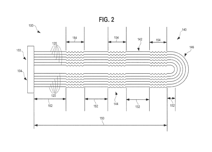
[0019] FIG. 2 representatively illustrates a partial side schematic
representation view of a heat exchanger 100 according to an exemplary
embodiment
provided herein, and more particularly to an exemplary bundle 140 of
individual tubes
120 having a generally U-shaped arrangement. As shown in FIG. 2, the U-shaped
bundle 140 of tubes 120 can comprise a plurality of generally elongated tubes
120
having at least a first leg portion 142 and a second leg portion 144 extending
substantially parallel to each other along their lengths. According to the
embodiment
illustrated in FIG. 2, it will be recognized that portions 142, 144 of tubes
120 within the
tube bundle 140 are in fluid communication with each other so that tube-side
fluid within
an interior passageway of the tubes can be permitted to flow in a first
direction along the
first leg portion 142 of a U-shaped tube 120 from an inlet 102 and into the U-
shaped
portion 146, where the tube-side fluid can reverse direction and flow back in
a second
direction, opposite to the first direction, along the second leg portion 144
of a U-shaped
tube 120 to an outlet 104.
[0020] Although FIG. 2 depicts the tube bundle 140 generally
comprising a
linear first leg portion 142 and a linear second leg portion 144 that are
joined by a
generally U-shaped portion 146, it will be understood that the tube bundle 140
can
comprise any of a number of shapes, whether presently known or later
developed,
including, without limitation, generally triangular shapes, generally
rectangular shapes,
and any similar symmetrical and non-symmetrical shapes or series of shapes
that are
joined by any number of rounded portions that have varying arc lengths and
radius
4
CA 03095856 2020-10-01
WO 2019/202557 PCT/IB2019/053246
sizes. Further, a preferred embodiment of the present invention can be used
with
alternate tube bundle arrangements including, for example, straight tube or
shell
arrangements, single or multi-pass arrangements, and/or designs implementing
parallel
(co-current) or counter-flow arrangements.
[0021] As shown schematically in FIG. 2, according to exemplary
embodiments the fluid tubes 120 of the tube bundle 140 can generally comprise
an
alternating series of individually segmented sections 150, in fluid
communication with
each other, comprising generally tubular straight sections 152 and sections
further
generally comprising a twisted configuration 154, which are twisted or rotated
along
their lengths about the respective central longitudinal axes 160 defined
thereby. For
example, FIG. 2 illustrates the first leg portion 142 and the second leg
portion 144 of
each tube 120 as having four straight sections 152 and three twisted sections
154 along
their lengths, including (in sequence, from left to right): a first straight
section 152, a first
twisted section 154, a second straight section 152, a second twisted section
154, a third
straight section 152, a third twisted section 154, and a fourth straight
section 152
leading into the U-shaped portion 146. Thus, each tube 120 of the tube bundle
140 is
shown as providing a series 150 of intermittent twisted sections 154 spaced
apart by
straight or untwisted tube sections 152. However, it will be understood that a
preferred
embodiment of the present invention can comprise a first straight section 152,
generally
corresponding with the entire length of the first leg portion 142, and a first
twisted
section 154, generally corresponding with the entire length of the second leg
portion
144, or any variation thereof. Further, although FIG. 2 depicts the
alternating series of
individually segmented sections 150 as being generally equal or consistent in
length, it
will be understood that the length of any straight section 152 or any twisted
section 154
can vary relative to any other straight section 152 or twisted section 154.
According to
exemplary embodiments as shown schematically in FIG. 2, the twisted tube
sections
154 of the plurality of tubes can be generally positioned in alignment with
one another
and the straight tube sections 152 can be generally positioned in alignment
with one
another.
[0022] As shown schematically in Fig. 2, in a preferred embodiment,
the
intermittent twisted sections 154 of the first leg portion 142 and the
intermittent twisted
sections 154 of the second leg portion 144 of each tube 120 within the tube
bundle 140
CA 03095856 2020-10-01
WO 2019/202557 PCT/IB2019/053246
can be aligned so that the twisted sections 154 of each leg portion are
generally
laterally adjacent to the twisted sections 154 of the other leg portion.
Although FIG. 2
illustrates a specific number and location of alternating twisted sections 154
and straight
sections 152, it will be understood that embodiments are not limited to such
and that
such alternating sections 150 can be provided in alternative numbers or
locations,
without limitation.
[0023] The twisted sections 154, interspersed between straight
sections
152, are advantageous because they can generally result in a more efficient
conversion
of pressure drop across the shell-side of the tubes 120 and the tube bundle
140.
Specifically, the twisted sections 154, and the arrangement thereof, can
mitigate the
negative effects of tube sagging and vibration of the tubes 120, because the
twisted
sections 154, and the arrangement thereof, increases the mechanical resonant
frequency of the tube 120, which can make the tubes 120 and any bundle 140 of
such
tubes 120 more resistant to lateral deflection from forces generated by shell-
side fluid
flow through the heat exchanger 100. In this way, the twisted sections 154,
and the
arrangement thereof with straight sections 152, eliminate the need for closely-
spaced
intermediate support structures or members at various points along the length
thereof
and, in some instances, the need for intermediate support structures or
members at all.
The improvement being advantageous over tubes, arrangements of tubes, and tube
bundles that comprise either entirely straight tubes or tubes that are twisted
over their
entire lengths, without the alternating series of individually segmented
straight sections
and twisted sections 150. Further, the twisted sections 154 can promote the
efficiency
of heat transfer between tube-side fluid and shell-side fluid when compared to
known
tube arrangements. First, by eliminating the need for closely-spaced
intermediate
support structures or members at various points on the length of the tube 120
or tube
bundle 140, such configuration requires less baffles, or even no baffles, to
support and
maintain the tubes 120 or the tube bundle 140, which reduces the inhibiting
effect of
such baffles on the flow of the shell-side fluid along the length of the
tubes. Second, by
eliminating the need for closely-spaced intermediate support structures or
members at
various points on the length of the tube 120 or tube bundle 140, such
configuration does
not create the excessive shell-side pressure drop common to known
configurations and
spacings of baffles used in heat exchangers.
6
CA 03095856 2020-10-01
WO 2019/202557 PCT/IB2019/053246
[0024]
FIG. 3 representatively illustrates a partial detail representation of
the side of a twisted section 154 of three (3) tubes 120 of a tube bundle 140
according
to exemplary embodiment. FIGS. 4-10 further depict representations of the
various
cross-sections at specific rotational intervals along the length of a segment
S of the
respective tubes 120 in FIG. 3. As best shown in FIGS. 3-10, between segment
S,
each tube 120 is twisted or rotated about a central longitudinal axis 160 at
least 3609, or
one complete revolution, with each cross-section view along segment S showing
rotation on the order of approximately 609 from any immediately adjacent cross-
section.
In a preferred embodiment, the segment S can be approximately between three
(3)
inches and sixteen (16) inches, or approximately between five (5) inches and
ten (10)
inches, depending on the diameter of the respective tube 120, which can vary
between
approximately 0.625 inches in diameter and one (1) inch in diameter. In a
preferred
embodiment, each tube 120 can complete two 3609 turns between any two
consecutive
straight sections 152. As shown schematically in FIG. 3, the exterior surfaces
of tubes
120 avoid contact along the straight sections 152.
[0025]
FIGS. 4-10 schematically illustrate rotation of tubes 120 within a
tube bundle 140 through a 360 portion of rotation along the twisted section
154.
Although the tubes 120 according to exemplary embodiments presented herein are
generally provided as having a round cross-section profile when oriented along
the
straight sections, FIGS. 4-10 show that such round cross-sectional profile is
compressed through the twisting of the tube bodies.
According to exemplary
embodiments, such compression can flatten the round-cross sectional profile
such that
the tubes take on a generally elliptical shape as shown in FIGS. 4-10. Such
compression can reduce the cross-sectional area of the tubes and causes
opposing
points on the sides of the tubes to protrude outward. As shown schematically
in FIGS
4-10, such protrusion can bring about contact 170 between exterior surfaces of
tube
bodies of adjacent tubes.
[0026] As
shown schematically in FIGS. 4-10, exterior surfaces of
adjacent tubes 120 of the tube bundle 140 can have a plurality of points of
contact 170
along the twisted section at certain rotation intervals. According to
exemplary
embodiments shown in FIGS. 4-10, rotation of the tube body of each of the
plurality of
tubes 120 in the twisted section can be synchronized such that the tubes 120
rotate
7
CA 03095856 2020-10-01
WO 2019/202557 PCT/IB2019/053246
together. For example, at commencement of a twisted section as shown
representatively in FIG. 4, the plurality of tubes 12 can be in an initial
rotation
orientation. From this orientation, as the tubes twist along the twisted
segment, the tube
body of each tube rotate together (tubes shown as being horizontally adjacent
to one
another in FIG. 4 with their end points in contact are shown as rotating
counterclockwise
towards the rotation interval shown in FIG. 5). In undergoing such rotation,
the tubes
shown as being in contact with one another in FIG. 4 taper away from one
another and
form new contacts (with another tube) at the rotation interval of FIG. 5. Such
contact
and separation continues as the tubes rotate through the twisted section. It
will be
recognized that FIG. 7 represents a rotation interval taken on the order of
180 from the
initial rotation orientation of FIG. 4. Accordingly, the right side of a tube
in FIG. 4 would
be shown as being the left side in FIG. 7.
[0027] Each of FIGS. 4-10 show tubes 120 of an exemplary tube bundle
140 at a particular rotation interval taken on the order of 60 through a full
360 of
rotation of a twisted segment. For example, with respect to an interior tube
of the tube
bundle 140 in FIG. 4 which is surrounded by adjacent perimeter tubes, such
interior
tube 120 can have a first point of contact 170 with an adjacent tube 120
directly to its
right and a second point of contact 170 with the adjacent tube 120 directly to
its left. In
FIG. 5, the centermost tube has the first point of contact 170 with the
adjacent tube 120
to its upper-right and the second point of contact 170 with the adjacent tube
120 to its
lower-left. In FIG. 6, the centermost tube 120 has the first point of contact
170 with the
adjacent tube 120 to its upper-left and the second point of contact 170 with
the adjacent
tube 120 to its lower-right. Then, in FIG. 7, the centermost tube 120 has the
first point
of contact 170 with the adjacent tube 120 directly to its left and the second
point of
contact 170 with the adjacent tube 120 directly to its right. In this way, the
centermost
tube 120 can encounter eight (8) different points of contact 170 through 180
of
revolution along a portion of segment S, as represented by FIGS. 4-7. In
contrast, as
shown in FIGS. 4-7, with respect to any tube 120 other than the centermost
tube 120 in
tube bundle 140, such tube can encounter four (4) different points of contact
170
through 180 of revolution along a portion of segment S. Although FIGS. 4-10
depict
twisted section 154 of a tube bundle 140 comprising seven individual tubes
120, with
various points of contact 170, it will be understood that the tube bundle 140
can
8
CA 03095856 2020-10-01
WO 2019/202557 PCT/IB2019/053246
comprise any number of tubes 120 with any number of points of contacts 170
without
limitation.
[0028] According to embodiments presented herein, and shown
representatively in FIGS. 2-10, the intermittent twisted sections 154 of the
tubes 120
can act as a support mechanism within the heat exchanger shell and further
eliminate
the need for baffles altogether. Further, the twisted nature of the twisted
sections 154
permits for larger voids 180 between each tube 120 in a tube bundle 140, as
best
illustrated in the cross-sections in FIGS. 4-10. The efficiency of heat
exchange
between the tube-side fluid and the shell-side fluid, via the tube wall, can
be further
improved over known heat exchangers by a swirl flow created by the twisted
segments
of tubes 120 and the voids 180. Specifically, the swirl flow can be created by
a swirling
region defined by the individual tubes 120 of the tube bundle 140, and
generally
comprising the voids 180 along the twisted sections. The shell-side fluid can
travel
between the voids 180, and the varying space defined thereby, and generally
along the
length of the tubes 120 and tube bundle 140. In this way, the shell-side fluid
can be
acted upon by the tubes 120 depending on the orientations thereof relative to
segment
S, as best depicted in FIGS. 4-10, to create a swirl effect in the shell-side
fluid, which
can produce a swirl flow.
[0029] Further, because a twisted section 154 is generally adjacent
to an
at least one straight section 152, wherein the tubes 120 of the tube bundle
140 are
generally arranged in a tighter arrangement with fewer and smaller voids
between the
tubes, the overall mechanical resonance of the tube 120 is not adversely
affected by the
spacing and voids 180 of the twisted section 154. The intermittent twisted
segments
154 can support the tubes 120 and tube bundles 140 within the shell in a
manner that
provides a highly flexible support system with enhanced heat transfer on the
tube- and
shell-side flows, such that each tube 120 or tube bundle 140 is generally self-
supporting, even without the use of baffles. Such support can be achieved, at
least in
part, by the twisted segments 154 which can produce tube-to-tube spaced-apart
contact
points 170 between adjacent tubes 120, while also defining the voids 180
discussed
herein, with each individual tube 120 being secured in place by adjacent tubes
120, and
facilitating securement of adjacent tubes 120. Such arrangement can reduce
vibration
and promote easier cleaning on the shell-side through the heat exchanger 100.
9
CA 03095856 2020-10-01
WO 2019/202557 PCT/IB2019/053246
* * *
[0030] It is important to note that the present inventions
(e.g.,
inventive concepts, and so on) have been described in the specification and/or
illustrated in the FIGURES of the present patent document according to
exemplary
embodiments; the embodiments of the present inventions are presented by way of
example only and are not intended as a limitation on the scope of the present
inventions. The construction and/or arrangement of the elements of the
inventive
concepts embodied in the present inventions as described in the specification
and/or
illustrated in the FIGURES is illustrative only. Although exemplary
embodiments of the
present inventions have been described in detail in the present patent
document, a
person of ordinary skill in the art will readily appreciate that equivalents,
modifications,
variations, and so on of the subject matter of the exemplary embodiments and
alternative embodiments are possible and contemplated as being within the
scope of
the present inventions; all such subject matter (e.g., modifications,
variations,
embodiments, combinations, equivalents, and so on) is intended to be included
within
the scope of the present inventions. It should also be noted that
various/other
modifications, variations, substitutions, equivalents, changes, omissions, and
so on may
be made in the configuration and/or arrangement of the exemplary embodiments
(e.g.,
in concept, design, structure, apparatus, form, assembly, construction, means,
function,
system, process/method, steps, sequence of process/method steps, operation,
operating conditions, performance, materials, composition, combination, and so
on)
without departing from the scope of the present inventions; all such subject
matter (e.g.,
modifications, variations, embodiments, combinations, equivalents, and so on)
is
intended to be included within the scope of the present inventions. The scope
of the
present inventions is not intended to be limited to the subject matter (e.g.,
details,
structure, functions, materials, acts, steps, sequence, system, result, and so
on)
described in the specification and/or illustrated in the FIGURES of the
present patent
document. It is contemplated that the claims of the present patent document
will be
construed properly to cover the complete scope of the subject matter of the
present
inventions (e.g., including any and all such modifications, variations,
embodiments,
combinations, equivalents, and so on); it is to be understood that the
terminology used
in the present patent document is for the purpose of providing a description
of the
CA 03095856 2020-10-01
WO 2019/202557 PCT/IB2019/053246
subject matter of the exemplary embodiments rather than as a limitation on the
scope of
the present inventions.
[0031] It is also important to note that according to exemplary
embodiments the present inventions may comprise conventional technology (e.g.,
as
implemented and/or integrated in exemplary embodiments, modifications,
variations,
combinations, equivalents, and so on) or may comprise any other applicable
technology
(present and/or future) with suitability and/or capability to perform the
functions and
processes/operations described in the specification and/or illustrated in the
FIGURES. All such technology (e.g., as implemented in embodiments,
modifications,
variations, combinations, equivalents, and so on) is considered to be within
the scope of
the present inventions of the present patent document.
11