Note: Descriptions are shown in the official language in which they were submitted.
CA 03096011 2020-10-02
WO 2018/187445 PCT/US2018/026047
POOL CLEANER WITH GEAR DRIVE AND
RELATED APPARATUS AND METHODS
Cross-Reference to Related Application
[0001] This application claims the benefit of U.S. Provisional Patent
Application
Serial No. 62/481,156, filed on April 4,2017, the contents of which are herein
incorporated
by reference in their entirety.
Field of the Invention
[0002] The present invention relates to pool cleaners, and more
particularly, to
drive mechanisms for pool cleaners and related apparatus.
Background of the Invention
[0003] A variety of water-driven pool cleaners have been developed over
the years,
falling into two basic categories: pressure-driven cleaners and suction-driven
cleaners.
In the former, the pool cleaner typically receives water from a pressurized
water return
connection, while in the latter the pool cleaner is connected to a suction
connection. In
pressure-driven cleaners, some type of venturi arrangement is utilized to
generate suction
for debris removal, which is then stored in some type of debris bag or other
storage
volume on the cleaner. In suction-driven cleaners, the suction force generated
via the
suction connection is generally used directly, and debris is typically removed
via the
suction connection. In both pressure- and suction-driven cleaners, there is
often a turbine
provided which is driven by the water flow and in turn used to drive wheels,
treads or the
like which impel the cleaner over the pool surface.
[0004] There is often gearing associated with these turbines for
transferring the
rotational motion generated by the turbine to the wheels or treads, as well as
gearing for
executing a mechanical "program" of periodic reversals and/or direction
changes. This
program feature can be necessary to ensure that the pool cleaner traverses all
of the pool
surface to be cleaned within a reasonable period of time.
1
CA 03096011 2020-10-02
WO 2018/187445 PCT/US2018/026047
[0005] Additionally, on wheeled or treaded cleaners, some clearance must
be
maintained between the pool surface and the bottom of the cleaner. To prevent
excessive
dispersal of suction forces and decreased cleaning effect, it is often
necessary to arrange
some type of skirt around the suction opening of the cleaner. These skirts are
sometimes
made flexible and/or segmented to avoid becoming caught on obstacles. While
components of existing pool cleaners exist to meet these and other functional
requirements, further improvements are possible.
Summary of the Invention
[0006] In view of the foregoing, it is an object of the present invention
to provide an
improved pool cleaner, including a gear drive for providing power thereto, as
well as
related apparatus and methods. According to an embodiment of the present
invention, a
pool cleaner includes a body, a water source connection, a gear drive and a
suspension
arrangement. The body defines a suction opening on a lower surface thereof.
The gear
drive is mounted to the body and includes a drive housing and a pair of gears
with
intermeshing teeth rotatably mounted in the drive housing. The drive housing
is in fluid
communication with the water source connection such that associated water flow
is
directed around the pair of gears, imparting rotational motion thereto. The
suspension
arrangement is driven by the gear drive and supports the body for motion over
a pool
surface.
[0007] According to an aspect of the present invention, the gear drive
drives an
alternator used to drive electrical components of the pool cleaner. A
microcontroller
powered by the alternator is configured with program instructions to control
the electrical
components.
[0008] According to another aspect of the present invention, a pool
cleaner
includes a skirt assembly extending from the lower surface of the body
surrounding the
suction opening, the skirt assembly includes a plurality of slide members
mounted in
respective slots extending inwardly from opposite sides of the lower surface
of the body,
each of the slide members extending downwardly from the lower surface of the
body and
being displaceable upwardly within its respective slot upon encountering an
obstruction.
2
CA 03096011 2020-10-02
WO 2018/187445 PCT/US2018/026047
[0009] According to an additional aspect of the present invention, a
first duct
extends into the body above the first suction opening, the first duct tapering
inwardly from
the first suction opening and incorporating a spiral pattern. The body can
further define
a second suction opening on the lower surface thereof, with a second duct
extending into
the body above the second suction opening, tapering inwardly from the second
suction
opening and incorporating a spiral pattern. The respective spin directions of
the spiral
patterns of the first and second ducts can be opposite.
[0010] These and other objects, aspects and advantages of the present
invention
will be better appreciated in view of the drawings and following detailed
description of
preferred embodiments.
Brief Description of the Drawings
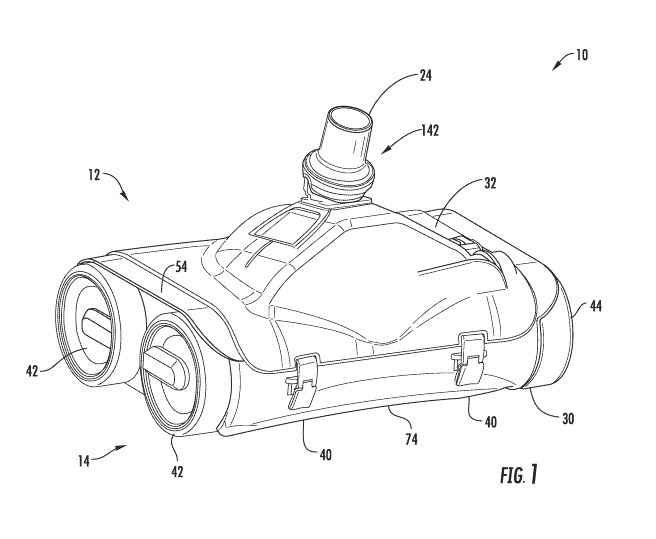
[0011] Figure 1 is an upper perspective view of a pool cleaner, according
to an
embodiment of the present invention;
[0012] Figure 2 is a lower perspective view of the pool cleaner of Figure
1, showing
a skirt assembly thereof;
[0013] Figure 3 is an upper perspective view of the pool cleaner of
Figure 1, with
a cover removed to show a gear drive and transmission assembly thereof;
[0014] Figure 4 is an upper perspective view of the pool cleaner of
Figure 1, with
the cover and a debris container removed;
[0015] Figure 5 is a side view of the chassis of the pool cleaner of
Figure 1, with
wheels removed to show skirt assembly component details;
[0016] Figure 6 is a rear view of the pool cleaner of Figure 1, with the
cover, the
debris container, and a chassis removed;
[0017] Figure 7 is a rear upper perspective view of the gear drive and
transmission
assembly of Figure 3;
[0018] Figure 8 is a forward upper perspective view of the gear drive and
transmission assembly of Figure 3, with some transmission assembly components
removed to show details;
[0019] Figure 9 is a front sectional view of the gear drive of Figure 3;
3
CA 03096011 2020-10-02
WO 2018/187445 PCT/US2018/026047
[0020] Figure 10 is a side view of a pool cleaner, according to another
embodiment
of the present invention;
[0021] Figure 11 is a rear view of a gear drive, according to another
embodiment
of the present invention;
[0022] Figure 12 is a sectional view taken along line 11-11 of Figure 11;
and
[0023] Figures 13 and 14 are schematic views of a pool cleaner, according
to
further embodiments of the present invention.
Detailed Description of Preferred Embodiments
[0024] Referring to Figures 1-4, according to an embodiment of the
present
invention, a pool cleaner 10 includes a body 12 supported for motion over a
pool surface
by a suspension arrangement 14. A skirt assembly 16 extending from a lower
surface of
the body 12 surrounds one or more suction openings 18 through which debris is
removed
from the pool surface. A gear drive 20 drives one or more elements of the
suspension
arrangement 14 via a transmission assembly 22, powered by water via a water
source
connection 24.
[0025] The body 12 includes a chassis 30 and a cover 32. The suspension
arrangement 14 is connected to the chassis 30, which supports the gear drive
20 and
transmission assembly 22. The suction openings 18 are formed through a lower
surface
34 of the chassis 30 with the skirt assembly 16 extending downwardly from
edges thereof.
The chassis 30 defines an upper opening 36 which is closed by the cover 32.
Preferably,
one or more releasable fasteners 40, such as latches, hold the cover 32 in
place over the
upper opening 36. The fit between the cover 32 and the chassis 30 should be
sufficiently
tight to avoid unwanted water flow therebetween and ensure sufficient suction
is
generated at the suction openings 18.
[0026] In the depicted arrangement, the suspension arrangement 14
includes a
plurality of wheels 42, one or more of which is driven by the gear drive 20
via the
transmission assembly 22. An appropriate tread 44 can be applied to all or a
portion of
the wheels 42 to ensure sufficient engagement with the underlying pool
surface. The
suspension arrangement 14 is not necessarily limited to a particular number or
configuration of wheels 42. For example, two- and three-wheel configurations
could also
4
CA 03096011 2020-10-02
WO 2018/187445 PCT/US2018/026047
be used. Additionally, other types of suspension arrangements could be
employed. For
instance, referring to Figure 10, a pool cleaner 10A could be equipped with a
suspension
unit 14A employing tracks 44A driven by drive wheels 42A (only one side
shown).
[0027]
Referring more particularly to Figures 2 and 5, the skirt assembly 16
includes side plates 50 and a plurality of slide members 52. The side plates
50 are
mounted to opposite sides 54 of the chassis 30 via elongated slots 56,
allowing the plates
50 to move upwardly as needed to avoid interference with the underlying pool
surface.
While unitary side plates 50 are shown in the depicted embodiment, it will be
appreciated
that segmented side plates 50 could also be used.
[0028]
The slide members 52 are arranged in slots 60 extending inwardly from the
sides 54 of the chassis 30. Each of the slide members 52 includes a retention
portion 62
retained within the slot 60 and a rounded lower portion 64 for engagement with
the pool
surface. A reduced thickness neck 66 extends through the slot 60 and connects
the
retention portion 62 and the lower portion 64. A free space 70 above each slot
60 allows
the slide member 52 to be urged upwardly, as needed, to permit larger debris
and/or pool
surface obstructions to pass thereunder. With the wheels 42 and side plates 50
removed,
the slide members 52 can be removed and replaced via the sides of the chassis
30.
[0029]
In the depicted embodiment, the slide members 52 are arranged in four
separate banks 72. Two banks 72 extend inwardly from opposite sides 54
proximate a
front side 74 of the chassis, while two banks 72 extend inwardly from opposite
sides 54
proximate a rear side 76 of the chassis 30. Advantageously, the forward banks
72 each
angle slightly to the rear and the rear banks 72 each angle slightly to the
front, such that
each set of two adjacent banks 72 forms a shallow "V" shape with an apex
directed toward
the center of the lower surface 34 of the chassis 30. This configuration can
assist in the
funneling of debris through the skirt assembly 16 during movement of the pool
cleaner 10
in forward and reverse directions. A straight configuration or other
configurations could
also be employed.
[0030]
Generally, the skirt assembly 16 increases the efficacy of the suction forces
imparted via the suction openings 18 at removing dirt and debris from the area
of the pool
surface immediately underlying the pool cleaner 10. Additionally, enhancing
the suction
effect, ducts 78 are located above the openings 18, which taper inwardly
therefrom and
CA 03096011 2020-10-02
WO 2018/187445 PCT/US2018/026047
incorporate a spiral pattern (see Figures 2 and 4). This channels and
increases the
velocity of water flow, helping to better ensure water-entrained debris is
drawn into the
body 12 of the pool cleaner. In the depicted embodiment, the spin direction of
the spiral
patterns are opposite for the two ducts 78.
[0031] While the skirt assembly 16 is particularly advantageous for use
in
connection with the depicted pool cleaner 10, it will be appreciated that the
skirt assembly
could be advantageously employed in connection with other pool cleaners,
including ¨ for
example ¨ pool cleaners not equipped with a gear drive 20 and/or pressure-
driven pool
cleaners.
[0032] Referring also to Figure 3, within the body 12, the ducts 78
terminate at
outlets 80 located within a filter basket 82. Consequently, with the cover 32
in place, all
water entering the body 12 via the suction openings 18 must pass through the
filter basket
82. Debris larger than an opening size of the filter basket 82 is therefore
retained within
the filter basket 82, from whence it can be periodically emptied by removing
the cover 32
and the basket 82. In the depicted embodiment, after passing through the
filter basket
82, water flow (and any remaining entrained debris) passes through the gear
drive 20 and
out through the water source connection 24.
[0033] The present invention is not necessarily limited to use in
connection with an
internal collection volume like the filter basket 82. For instance, a pool
cleaner without
any sort of collection volume could be used (i.e., such that all debris was
simply passed
to the pool water recirculation system for removal). Additionally, external
collection
volumes could be used; for example, external collection bags used in
connection with
certain pressure-driven cleaners).
[0034] Referring to Figures 6-9, the gear drive 20 includes a drive
housing 84
having lower and upper openings 86, 90. A pair of gears 92 with intermeshing
teeth are
rotatably mounted to the housing 84. In the depicted pool cleaner 10, water is
drawn in
through the lower opening 86, from whence it travels along the sides of the
housing 84 to
the upper opening 90 causing the gears 92 to counter-rotate as indicated by
arrows 94.
The gears 92 are mounted on axles 96 supported by the housing 84.
[0035] The depicted shape of gear teeth 98 is believed to be preferred,
but other
shapes and configurations can be used in connection with the present
invention. The
6
CA 03096011 2020-10-02
WO 2018/187445 PCT/US2018/026047
tolerance between gears 92/teeth 98 should be close enough to result in
sufficient force
generation due to water flow while loose enough to permit expected debris to
pass without
jamming. To further facilitate passage of debris, the gears 92 could be
resiliently mounted
on the axles 96 and/or the teeth 98 resiliently mounted to the gears, with the
play afforded
thereby allowing larger obstructions to pass. Additionally, while the depicted
gears 92
are molded to be hollow, cavities could be machined in the gears or solid
gears could be
used.
[0036]
The gear drive 20 is mounted to the chassis 30 via a frame 100, holding
the gear drive 20 above the lower surface 34 of the chassis 30. In the
depicted
embodiment, the gear drive 20 is mounted transversely, such that the axes of
the gears
92 are generally perpendicular to the axes of the wheels 42. In other
embodiments, the
gear drive could be mounted fore-and-aft, such that the gear 92 axes would be
parallel
with the wheel 42 axes.
[0037]
The gears 92 are fixedly mounted on axles 96, such that the rotational
output of the gear drive 20 comes from the axles 96. However, the rotational
output could
be taken directly from the gears, allowing a fixed axle to be used. Also, the
gears need
not have parallel axes ¨ gears intermeshing at a 90 degree angle could be
used, for
instance. Additionally, one or more intermediate gears could be used. For
example, with
a single intermediate gear located between the outer gears, the outer gears
would both
rotate in the same direction. More than one gear drive could also be included,
with the
multiple gear drives being interconnected or mechanically independent.
[0038]
The transmission assembly 22 is commonly mounted on the frame 84 with
the gear drive 20, and includes a transmission housing 102 to prevent fouling
of
transmission assembly 22 components and facilitate installation and
replacement as a
unit. The transmission assembly 22 is driven via engagement with at least one
axle 96
of the gear drive 20, and includes a drive section 104 for transferring
rotational motion
from the axle 96 to the suspension arrangement 14, and a program section 106
for
periodically altering a drive direction of the suspension arrangement 14.
[0039]
In the depicted embodiment, the drive section 104 includes an output gear
110 connected to one the gear drive 20 axles 96. The rotational speed of the
gear 110
is stepped down via engagement with a first intermediate gear 112. First
intermediate
7
CA 03096011 2020-10-02
WO 2018/187445 PCT/US2018/026047
gear 112 turns the second intermediate gear 114, which engages a third
intermediate
gear 116 at an angle ¨ effecting a 90 degree shift in the axis of rotational
motion. The
third intermediate gear 116 has inner and outer races 120, 122, with the outer
race 122
driving the program section 106 and the inner race 120 engaging a suspension
drive gear
124 via an output of the program section 106.
[0040] In an alternate embodiment, some or all of the transmission
assembly could
be located inside the gear drive. For example, referring to Figures 11 and 12,
in a gear
drive 20B, a drive section 104B of a transmission assembly is located inside
one of the
gears 92B. Specifically, rotation of the gear 92B drives a planetary input
gear 110B
rotatably mounted therein, which drives a planetary output gear 112B at a
reduced
rotational speed via intermediate planetary gears 114B.
[0041] The program section 106 includes a plurality of successively
driven timing
gears 126 and a pivotable dual gear yoke 130. The dual gear yoke 130 mounts
twin
intermeshing gears 132, 134 and an engagement post 136. The dual gear yoke 130
is
pivoted upwardly or downwardly based on engagement of the post 136 with a cam
surface
140 extending partially around the last timing gear 126. When the cam surface
140
engages the post 136, the yoke 130 is urged upwardly, and the gear 132
transfers
rotational motion directly between the inner race 120 of the third
intermediate gear 116
and the suspension drive gear 124 ¨ resulting in the suspension drive gear 124
rotating
in the same direction as the third intermediate gear 116. When cam surface 140
is rotated
out of engagement with the post 136, the yoke 130 pivots downwardly, and the
gear 132
transfers rotational motion indirectly to the suspension drive gear 124 via
the gear 134 ¨
resulting in the suspension drive gear 124 rotating in an opposite direction
from the third
intermediate gear 116.
[0042] The suspension drive gear 124 drives at least one of the wheels 42
(or other
suspension component) via a drive shaft 140. Preferably the drive shaft 140
drives two
opposite wheels 42 for motion in the forward direction, while a unidirectional
clutch or the
like disengages one of the wheels 42 during movement in the reverse direction
¨ thus
helping to vary the travel pattern of the pool cleaner 10 over the pool
surface. Additionally,
the transmission assembly 22 could be configured to allow user selection of
cleaner 10
8
CA 03096011 2020-10-02
WO 2018/187445 PCT/US2018/026047
speed ¨ for instance, allowing a user to choose between a more thorough
cleaning at a
slower speed and quicker cleaning at a faster speed.
[0043] In the depicted pool cleaner 10, only one gear drive 20 axle 96 is
used to
drive a single transmission assembly 22. However, the presence of two axles 96
permits
the use of two transmission assemblies 22 independently driving the suspension
arrangement 14 on opposite sides of the cleaner 10. Various other transmission
assemblies 22 could also be employed ¨ including assemblies not featuring
program
functions. The gear drive 20 could also be used to drive other pool cleaner 10
components, such as an alternator for supplying electrical components (e.g.,
lights,
motors, microcontrollers, etc.).
[0044] Referring again to Figure 1, at the upper opening 90 of the gear
drive, the
water source connection 24 advantageously includes a swivel ball mechanism
142,
allowing a connected hose to both rotate and pivot fore-and-aft relative to
the pool cleaner
10. Other connections could also be employed, as desired. The depicted pool
cleaner
is a suction-driven pool cleaner; it will be appreciated that the gear drive
20 could
readily be employed in a pressure-driven cleaner to drive a suspension
arrangement
thereof. Additionally, the gear drive could be employed to generate motive,
program
and/or electrical power in other types of pool tools. For example, the gear
drive could be
employed in a surface skimmer, a combination vacuum/skimmer, etc.
[0045] As noted above, the gear drive 20 could be used to power an
alternator to
supply electrical components. Such an arrangement can greatly increase the
range and
flexibility of functions offered in a pool cleaner. For example, referring to
Figure 13, a pool
cleaner 10C includes a gear drive 20C driving an alternator 150C to generate
electrical
power. The alternator 150C can be of any suitable type, although an AC
induction-type
machine is particularly suitable. Such an alternator can include a rectifier
to convert the
electrical power generated by the alternator into DC power and/or additional
circuitry for
power conditioning, as necessary.
[0046] In the embodiment of Figure 13, the suspension arrangement 14C
includes
electric motors 152C powered by the alternator 150C to drive the wheels 42C
via drive
shafts 140C. Advantageously, a microcontroller 154C is included. Powered by
the
alternator 150C, the microcontroller 154C is configured with program
instructions to
9
CA 03096011 2020-10-02
WO 2018/187445 PCT/US2018/026047
control the motors 152C, allowing it to control speed and direction of the
motors 152C, as
well as to differentially operate the motors to steer the pool cleaner 10C.
[0047]
An ambient sensor 160C powered by the alternator 150C and also
communicating the microcontroller 154C is beneficially further included.
Various types
and numbers of ambient sensors can be included to detect different pool
conditions (e.g.,
dirt levels, presence of obstacles, light levels, chemistry conditions, etc.)
The
microcontroller 154C can be further configured with program instructions to
alter pool
cleaner operation based on the detected pool condition(s) (e.g., to move
slower where
dirt levels are greater, to steer around obstacles, to turn on external lights
at night, to
dispense chemicals, etc.).
[0048]
In a different embodiment, referring to Figure 14, the pool cleaner 10D is
equipped with an alternator 150D driven by the gear drive 20D. The gear drive
20D also
mechanically drives the wheels 42D via the drive section 104D of a
transmission
assembly 22D and a split axle 140D. However, the program section 106D of the
transmission assembly 22D is controlled by the microcontroller 154D, which is
configured
with program instructions to operate the program section 106D and thereby vary
how
mechanical power is applied to the wheels 42D via the drive section. An
ambient sensor
160D can also be included in communication with the microcontroller 154D,
allowing
functions like those discussed in connection with the microcontroller 154C.
[0049]
The foregoing is provided for illustrative and exemplary purposes; the
present invention is not necessarily limited thereto. Rather, those skilled in
the art will
appreciate that various modifications, as well as adaptations to particular
circumstances,
are possible within the scope of the invention as herein shown and described
and of the
claims appended hereto.