Note: Descriptions are shown in the official language in which they were submitted.
SECUREMENT DEVICE HAVING AN INTEGRAL STRAP AND DRESSING
BACKGROUND
Field of the Invention
[0001] The present invention relates generally to techniques, systems,
and devices for
securing a catheter, catheter extension set, and/or other medical article on a
patient.
Description of the Related Art
[0002] Medical patients are often in need of repetitious administering of
fluids or
medications, or repetitious draining of fluids. It is very common in the
medical industry to utilize
medical tubing to provide various liquids or solutions to a patient. For
example, medical tubing
such as a catheter is often used to introduce fluids and medications directly
into the patient or to
withdraw fluids from the patient. In many cases, the catheter remains in place
for many days. In
some instances, a catheter may be attached to a patient for an even lengthier
period of time, and
may require minimal movement for proper functioning.
[0003] It is often advantageous to restrict the movement of the catheter.
A moving catheter
may cause discomfort to the patient, restrict the administering of fluids or
medications or the
draining of fluids, cause infection, or become dislodged from the patient
unintentionally. In order
to keep the catheter or other medical tubing properly positioned for the
duration of treatment, the
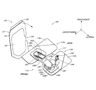
catheter or medical tubing can be stabilized on the patient in a variety of
ways. Most commonly,
the medical provider may attempt to restrict movement of the catheter by
securing the distal end
of the catheter, or a portion of a medical device connected to the catheter
such as a connector
fitting, to the patient using tape. Medical providers commonly place long
pieces of tape across the
distal end of the catheter, often in a crisscross pattern, to secure the
catheter distal end to the patient.
This securement is intended to inhibit disconnection between the catheter and
the patient or
between the catheter and another medical article, such as a drainage tube, as
well as to prevent the
catheter from catching on other objects, such as on a bed rail.
[0004] Stabilizing a catheter with tape upon the patient, however, has
certain drawbacks.
For example, taped connections often collect contaminants and dirt. This
potentially can lead to
infection of the patient, particularly at an insertion site where the catheter
is inserted into the
-1-
Date Recue/Date Received 2022-05-17
patient. Taped stabilization typically leaves the insertion site exposed to
these contaminants and
dirt and other foreign objects that may be harmful to the patient and/or
compromise the
stabilization of the catheter. Gathering or collecting of contaminants by the
tape may exacerbate
any problems at the insertion site. Normal protocol therefore requires
periodic tape changes in
order to inhibit germ growth. Such periodic changes, however, often disrupt
any attempts or
mechanisms used to shield or protect the insertion site, and may compel
detrimental manipulation
of the areas around the insertion site. Furthermore, it may be desirable to
keep the insertion site
of the medical article dry and/or otherwise protected from the external
environment in order to
reduce infections in and around the insertion site.
BRIEF DESCRIPTION OF DRAWINGS
[0005] The above mentioned and other features of the invention will now
be described
with reference to the drawings of several embodiments of the present
stabilization system. The
illustrated embodiments of the stabilization system are intended to
illustrate, but not to limit the
invention. The drawings contain the following figures:
[0006] Figure 1 is a perspective view of an embodiment of a securement
device having an
integral strap and dressing.
[0007] Figure 2 is a top view of the securement device of Figure 1.
[0008] Figure 3A is a cross-sectional view of the securement device of
Figure 2 taken
along the line 3A-3C according to one embodiment.
[0009] Figure 3B is a cross-sectional view of the securement device of
Figure 2 taken along
the line 3A-3C according to another embodiment.
[0010] Figure 3C is a cross-sectional view of the securement device of
Figure 2 taken along
the line 3A-3C according to another embodiment.
[0011] Figure 4 is a front view taken from the proximal end of the
securement device of
Figure 1.
-2-
Date Recue/Date Received 2022-05-17
[0012] Figure 5 is a rear view taken from the distal end of the securement
device of
Figure 1.
[0013] Figure 6 is another perspective view of the securement device of
Figure 1 and
shows a medical article positioned above the device.
[0014] Figure 7 is another perspective view of the securement device of
Figure 1 and
shows a medical article placed in the open retainer.
[0015] Figure 8 is a top view of the securement device of Figure 1 secured
to a patient with
the dressing folded against the patient with the retainer in the closed
position.
[0016] Figure 9 is a cross-sectional view taken along the line 9-9 of the
securement device
of Figure 8 with the medical article placed in the closed retainer.
[0017] Figure 9A is a partial top view of the securement device of Figure
8 with the strap
removed.
[0018] Figure 10 is a perspective view of a medical article.
[0019] Figure 11 is an exploded view of the medical article of Figure 10.
[0020] Figure 12 is another perspective view of the medical article of
Figure 10.
[0021] Figure 13 is a perspective view of the medical article of Figure 10
being used with
a patient.
[0022] Figure 14 is another perspective view of the medical article of
Figure 10 being used
with a patient.
[0023] Figure 15 is another perspective view of the medical article of
Figure 10 being used
with a patient.
[0024] Figure 16 is a perspective view of another embodiment of a
securement device
having an integral strap and dressing.
-3-
Date Recue/Date Received 2022-05-17
[0025] Figure 17 is a top view of the securement device of Figure 16
secured to a patient
with the dressing folded against the patient with the retainer in the closed
position.
DETAILED DESCRIPTION OF CERTAIN EMBODIMENTS
[0026] The following description and examples illustrate preferred
embodiments of the
present securement device disclosed in the context of use with exemplary
catheters. More
specifically, the embodiments relate to a stabilization device and related
techniques that stabilize
a medical article in position on a patient. The embodiments of the securement
device are illustrated
with a catheter in use as part of a peripheral intravenous ("I.V.") line.
[0027] It will be understood by those of skill in the art in view of the
present disclosure
that the securement device described can be used with other types of medical
articles, including,
but not limited to catheters and catheter hubs of various design, either with
or without connectors
or extension sets, such as central venous catheters, peripherally inserted
central catheters,
hemodialysis catheters, Foley catheters, as well as other designs of catheter
hubs and catheter
adaptors. Other medical articles may include surgical drainage tubes, feeding
tubes, chest tubes,
nasogastric tubes, rectal drains, external ventricular drains, chest tubes;
any other sort of fluid
supply or medical lines, connector fittings, and scopes, as well as electrical
wires or cables
connected to external or implanted electronic devices or sensors. The medical
articles can be a
single medical article or a combination of medical articles.
[0028] The securement device described herein is especially adapted to
arrest at least
transverse movement of a catheter, as well as to hold medical articles against
the patient and protect
an area in proximity to an insertion site. The securement device accomplishes
this without
meaningfully impairing (i.e., substantially occluding) fluid flow through a
lumen of the medical
article or impairing insertion of the medical article. In some embodiments,
retention mechanisms
to accomplish this include a channel, a strap that is securable about a
medical article, and an
integrated dressing. In other embodiments, retention mechanisms to accomplish
this include a
retention mechanism having a catheter hub, retainer having a channel shaped to
receive the hub,
and an integrated strap and dressing. The securement device may also prevent
movement in a
distal and/or proximate direction with respect to the longitudinal axis. In
some embodiments,
retention mechanisms to accomplish this include a retainer having at least one
abutment.
-4-
Date Recue/Date Received 2022-05-17
[0029] Some embodiments of the securement device releasably engage a
catheter hub. An
extension set or other medical article can then be attached to the secured
catheter hub. This allows
the extension set to be disconnected from the securement device, and from the
patient, for any of
a variety of known purposes, while leaving the catheter secured to the
patient. For instance, the
medical provider may want to remove the extension set to clean or replace the
extension set or to
clean an area surrounding where the extension set is located on the patient.
The disengagement of
the extension set from the securement device, however, can be accomplished
without removing an
anchor pad, dressing, and/or releasing a retention mechanism. Thus, the
medical provider may
move the extension set without irritating the skin of the patient or
disrupting a catheter (for
instance, a cannula) inserted in the skin of the patient.
[0030] With reference now to Figure 1, an embodiment of a securement
device 100
includes anchor pads 110a and 100b, base members 130a and 130b, a dressing
120, and a retainer
200. The anchor pad 110 is configured to be secured to a patient's skin. The
base members 130a
and 103b are attached to an upper surface of the anchor pads 110a and 100b and
configured to
support the retainer 200. The retainer 200 is configured to engage a medical
article, for example
a catheter or catheter hub, as will be described in additional detail below.
[0031] To assist in the description of the components of embodiments of
the securement
device, the following coordinate terms are used, consistent with the
coordinate axes illustrated in
Figure 1. A "longitudinal axis" is generally parallel to a channel formed by
anchor pads 110a and
110b and spanned by the retainer 200. A "lateral axis" is normal to the
longitudinal axis and is
generally parallel to the plane of the retainer 200. A "transverse axis"
extends normal to both the
longitudinal and lateral axes. In addition, as used herein, "the longitudinal
direction" refers to a
direction substantially parallel to the longitudinal axis; "the lateral
direction" refers to a direction
substantially parallel to the lateral axis; and "the transverse direction"
refers to a direction
substantially parallel to the transverse axis. The terms "proximal" and
"distal" are used in
reference to the center of the patient's body, as will be understood by one of
skill in the art.
[0032] As can be seen in Figure 1, the anchor pads 110a and 110b are
positioned roughly
parallel to each other and spaced apart by a gap 111. The gap 111 can form a
channel along the
longitudinal axis for receiving a medical article such as a catheter. As will
be described in greater
-5-
Date Recue/Date Received 2022-05-17
detail below, the anchor pads 110a and 110b of the embodiment shown in Figure
1 are shaped for
use on a hand of a patient. However, other shapes and configurations of anchor
pads 110a and
110b are possible and within the scope of this disclosure. In some
embodiments, one anchor pad
is used.
[0033] The anchor pads 110a and 110b have a lower adhesive surface (not
shown) which
may adhere to the skin of a patient and an upper layer. The upper layer of the
anchor pads 110a
and 110b is configured to support at least the retainer 200. In some
embodiments, the upper layer
is configured to support at least the base members 130a and 130b. In
combination, the lower
adhesive surface, upper layer, and possibly one or more intermediate layers
may comprise a
laminate structure. A suitable laminate that comprises a foam or woven
material with an adhesive
layer is available commercially from Avery Dennison of Painsville, Ohio. The
anchor pads 110a
and 110b may be configured as a flexible structure configured to conform to
the surface of a
patient's skin.
[0034] The lower adhesive surface or layer may be a medical-grade
adhesive and can be
either diaphoretic or nondiaphoretic, depending upon the particular
application. The lower
adhesive surface may have additional types of medical adhesives laminated
thereto. In some
embodiments, the lower adhesive layer comprises an anti-bacterial or anti-
microbial material. For
example, the lower adhesive layer may comprise one or more oligodynamic metal
salts or oxides,
or a combination of salts and oxides. In some embodiments, the lower adhesive
layer comprises
a silver material, for example a silver salt, colloid, or complex. The
adhesive surface may be a
solid layer or may be configured as an intermittent layer such as in a pattern
of spots or strips. The
lower adhesive surface can be applied to the anchor pads 110a and 110b during
manufacture, and
may be further covered with a release liner as described below. Alternatively,
it is possible to
apply a double-sided adhesive tape to the upper layer before application.
[0035] The upper layer of the anchor pads 110a and 100b may comprise a
foam (e.g.,
closed-cell polyethylene foam) or woven material (e.g., tricot) layer. A
surface of the foam or
woven material layer constitutes the upper layer of the anchor pads 110a and
110b. In the
alternative, the upper layer may comprise an upper paper or other nonwoven
cloth layer, and an
inner foam layer may be placed between the upper layer and lower adhesive
surface.
-6-
Date Recue/Date Received 2022-05-17
[0036] As shown, the anchor pads 110a and 110b include removable release
liners 115a
and 115b on a lower surface of the anchor pads 110a and 110b. The removable
release liners 115a
and 115b may cover the lower adhesive surface before use. The release liners
may resist tearing
and be divided into a plurality of pieces to assist removal of the release
liners and ease attachment
of the anchor pads 110a and 110b to a patient's skin. The release liners may
be divided into two
adjacent pieces. The liners may be made of a paper, plastic, polyester, or
similar material. For
example, the release liners 115a and 115b may comprise a material made of
polycoated, siliconized
paper, or another suitable material such as high density polyethylene,
polypropylene, polyolefin,
or silicon coated paper. As illustrated in Figure 1, the release liners 115a
and 115b include tabs
that extend beyond the edge of the anchor pads 110a and 110b to allow a
medical provider to easily
grip the release liners 115a and 115b and remove them from the anchor pads
110a and 110b. The
tabs may be located at any edge of the anchor pads 110a and 110b and may be
any suitable size or
shape.
[0037] With reference now to the dressing 120, it can be seen in Figure 1
that the dressing
120 is attached to and/or integrated with anchor pad 110a. The dressing 120 is
configured to fold,
bend, or rotate down over the insertion site area 116 defined by the area in
between the anchor
pads 110a and 110b and proximal to the retainer 200. A proximal extended
portion of the anchor
pad 110a can provide an attachment area to attach or integrate the dressing
120 with the anchor
pad 110a. Additionally, the extended portion may longitudinally offset the
dressing 120 from a
location where the retainer 200 is supported by the anchor pad 110a such that
when the dressing
120 is folded down over the insertion site, the dressing 120 will not
substantially cover or obstruct
a catheter hub stabilized by the securement device 100 or the retainer 200
itself.
[0038] The dressing 120 and the anchor pad 110a may be formed as an
integral, single
piece. Alternatively, the dressing 120 and the anchor pad 110a may be formed
separately and then
attached together. In this case, the dressing 120 and the anchor pad 110a may
be attached by any
means or mechanism that allows the dressing 120 to fold, bend, or rotate down
over the insertion
site area. Attachment means include glue or adhesive, a weld of the materials,
heat sealing,
mechanical fasteners such as staples or eyelets, or other such means of
attachment. The anchor
pad 110a may be configured in any shape and size that allows attachment or
integration of the
dressing 120 with the anchor pad 110a. The dressing 120 may be attached to an
upper surface of
-7-
Date Recue/Date Received 2022-05-17
the anchor pad 110a, for example within an outer circumference of the anchor
pad 110a. In the
illustrated embodiment, the dressing 120 is secured to an edge of the anchor
pad 110a that is
generally parallel to a longitudinal axis. The dressing 120, however, may be
attached to or
integrated with the anchor pad 110a such that the dressing 120 is skewed with
respect to a
longitudinal and/or a lateral axis.
[0039] In some embodiments, the anchor pad 110a, the dressing 120, and/or
the attachment
means described above are configured to allow selective disconnection of the
dressing 120 from
the anchor pad 110a. For example, when the anchor pad 110a and the dressing
120 are integrally
formed, the region in which the dressing pad 120 folds may be scoured such
that a medical provider
may tear the dressing 120 away from the anchor pad 110a. Of course, other
means of removal or
release may be employed to allow the dressing 120 to be disconnected from the
anchor pad 110a.
[0040] A release liner 121 may cover an adhesive surface 124 of the
dressing 120 and may
also cover an occlusive layer 126 of the dressing 120, as shown in Figure 1.
The adhesive surface
124 is configured to adhere to the skin of a patient and/or to portions of the
upper layer of the
anchor pads 110a and 110b. The release liner 121 may cover the entire surface
of the dressing 120
or may only cover adhesive portions of the dressing 120. As illustrated in
Figure 1, the release
liner 121 covers less than the entire surface of the dressing 120 and the edge
122 of the dressing is
not covered by the release liner 121. In this way, the uncovered edge 122 can
function as a tab,
allowing a medical provider to easily grip the release liner and remove it
from the dressing 120.
In some embodiments, the release liner 121 extends past the edge of the
dressing to form a tab.
The tab may be located at any edge of the dressing 120, or a tab that projects
out from the release
liner 121 may be located within an area defined by the edges of the dressing
120. The release liner
121 may include an anti-microbial or anti-bacterial material or coating,
and/or have silver particles
dispersed throughout. The dressing 120 and release liner 121 may be prepared
such that the release
liner 121 maintains a covered surface of the occlusive layer 126 in a
sterilized state. The release
liner 121 may be configured similar to the release liner covering the lower
adhesive surface of the
anchor pad 110, described above.
[0041] In the illustrated embodiment, the adhesive surface 124 is formed
in a ring shape
on the periphery of the occlusive layer 126. This ring configuration will
encircle the insertion site
-8-
Date Recue/Date Received 2022-05-17
area when the adhesive layer 124 is adhered to the skin of the patient, but
will not adhere to the
point of insertion. Advantageously, this will reduce the likelihood of
aggravating or excoriating
the insertion site or skin around the insertion site, and will reduce the
likelihood of introducing
contaminants and/or liquid near or into the point of insertion. In addition,
the adhesive surface
124 will not contact the catheter 610 or catheter hub 630 when the adhesive
surface 124 is adhered
to the skin. The ring is broken at a notch or indent 128 in the occlusive
layer 126 to allow a catheter
and/or catheter hub to be covered without being contacted by the adhesive
surface 124. Thus, the
adhesive surface will not adhere or stick to the catheter and/or the catheter
hub. In this way, sticky
residues and buildup on the catheter and catheter hub may be reduced or
avoided.
[0042] The adhesive surface 124 may instead cover all or a majority of
the occlusive layer
126. Such configuration will increase the contact area of the adhesive surface
124 with the skin
of the patient and with portions of the anchor pads 110a and 110b, and may
result in a more secure
attachment of the dressing 120 to the patient. The adhesive surface 124 may be
configured similar
to the lower adhesive surface of the pads 110a and 110b, described above.
[0043] The occlusive layer 126 is configured to be waterproof or
otherwise impermeable
to liquids and in some embodiments also restricts the flow of air. In other
embodiments, the
occlusive layer 126 may be configured to be breathable, allowing air and/or
moisture near an
insertion site through to the other side of the occlusive layer 126 and away
from the insertion site,
while keeping at least external moisture on the other side of the occlusive
layer 126 away from the
insertion site. In some embodiments, the occlusive layer 126 is impermeable to
viruses and
bacteria, and may comprise or be coated with an anti-bacterial or anti-
microbial material. In some
embodiments, the occlusive layer 126 comprises or is coated with a waxy
material. In some
embodiments, the occlusive layer 126 comprises a film which may or may not be
transparent.
[0044] Selection of a transparent film or semi-transparent film for use
as the occlusive
layer 126 may allow a medical provider to see the insertion site and any
administered catheter. In
this way, potential infections or inflammation may be visualized through the
transparent film. In
some embodiments, the occlusive layer 126 is absorbent. In some embodiments,
the occlusive
layer 126 comprises an absorbent acrylic, an alginate, foam, a hydrocolloid,
and/or a hydrogel
material, and/or may comprise a silver material, for example a silver salt,
colloid, or complex. In
-9-
Date Recue/Date Received 2022-05-17
one embodiment, one or more oligodynamic metal salts or oxides, or a
combination of salts and
oxides are used in or on the occlusive layer 126 as an antimicrobial agent. In
some embodiments,
the occlusive layer 126 is configured similar to the upper layer of the anchor
pads 110a and 110b.
[0045] As described above, the occlusive layer 126 comprises a notch or
indentation 128.
This notch may reduce stress on the dressing 120 when the dressing is applied
over a catheter
and/or catheter hub. The dressing 120 may be configured to provide a
waterproof seal around an
insertion site when applied to the skin of a patient over a catheter and/or
catheter hub. In some
embodiments, the dressing 120 is still breathable while the waterproof seal is
created.
[0046] In some embodiments, the dressing 120 comprises a hemostatic
dressing. In such
embodiments, securing the dressing 120 over an insertion site or other wound
may inhibit blood
from flowing from the site. For example, the dressing 120 may comprise or be
coated with a
hemostatic or antihemorrhagic agent such as chitosan or other polysaccharide,
a collagen like
microfibrillar hemostat, anhydrous aluminum sulfate, potassium alum, titanium
dioxide, a gelatin,
or a solution of thrombin.
[0047] Continuing with Figure 1, the base members 130a and 130b can have a
lower
surface secured to the upper surface of the anchor pads 110a and 110b and an
upper surface secured
to at least a portion of the lower surface of the retainer 200. Although the
base members 130a and
130b are shown as having a roughly rectangular shape with rounded ends, the
base members 130a
and 130b may be shaped in any of a multitude of ways. The base members 130a
and 130b can be
formed with the same or different materials as the retainer 200. In one
embodiment, the base
members 130a and 130b and the retainer 200 comprise a single, integral piece.
The base members
130a and 130b, anchor pads 110a and 110b, and retainer 200 may be secured
together by any
means or mechanism including glue or adhesive, a weld of the materials, heat
sealing, mechanical
fasteners such as staples or eyelets, or other such means of attachment. In
some embodiments, the
base members 130a and 130b are semi-rigid or flexible. In this way, the base
members 130a and
130b can provide a transition between the relatively pliable anchor pads 110a
and 110b and the
relatively rigid retainer 200. For example, the base members 130a and 130b may
help secure the
retainer 200 to the anchor pads 110a and 110b and stabilize the retainer 200
so as to better
withstand twisting about the lateral axis.
-10-
Date Recue/Date Received 2022-05-17
[0048] With reference now to the retainer 200, it can be seen in Figure 1
that the retainer
200 comprises an open channel 234, a strap 240, and two angled supports 250
and 255. The
retainer 200 is attached to and supported by the base members 130a and 130b
and is configured
such that the retainer 200 does not rock or otherwise pivot on the base
members 130a and 130b.
In some embodiments, the retainer 200 is permanently adhered or affixed to the
base members
130a and 130b.
[0049] The open channel 234 has a curvilinear shape configured to accept
at least a portion
of a medical article. In the illustrated embodiment, the open channel 234 is
configured to accept
a catheter hub and thus the shape of the channel 234 approximates at least a
portion of the catheter
hub. The channel 234 is shown as having an approximately semi-conical shape,
but may be formed
as having a different shape. In the illustrated embodiment, the width of the
channel 234 in the
lateral direction varies in width such that a portion of the channel tapers in
a direction from distal
to proximal, but the channel 234 may be a consistent width or tapered along
the entire channel.
As will be described below, the channel 234 may be configured to accept
various medical articles.
[0050] A strap 240 is attached to the first angled support 255. The strap
240 is configured
to close over the open channel 234 and onto the second angled support 250 to
form an enclosed
area. When at least a portion of a medical article is placed inside the
channel 234, the strap 240
can be moved over the medical article to retain or stabilize the medical
article within the retainer
200 by, for example, applying a downward force onto the medical article and
thus maintaining at
least a portion of the medical article on a surface of the channel 234. The
strap 240 may be integral
to the first angled support 255, or may be attached thereto. In one
embodiment, the strap 240 is
integral to the first angled support 255 and attached by a living hinge. In
another embodiment, the
strap 240 is formed separate from the first angled support 255 and attached
thereto, for example
by sonic welding. A multitude of attachment means may be used to attach the
strap 240 to the first
angled support 255 such that the strap 240 may be closed over the channel 234
and onto the second
angled support 250.
[0051] As illustrated in Figure 1, the strap 240 is attached to the first
angled support 255
by a pin 242 that passes through the first angled support 255 and the strap
240. As such, the strap
240 can rotate about the pin 242 to cover and uncover the channel 234. The
first angled support
-11-
Date Recue/Date Received 2022-05-17
255 includes grooves 258a and 258b for receiving a portion of the strap 240
when the strap 240 is
in a closed position.
[0052] In one embodiment, the strap 240 comprises an elastomeric
material. In this
embodiment, the strap 240 may be stretched or deformed slightly when closing
about a medical
article placed in the channel 234. That is to say, the strap 240 may conform
to the outer surface
of a medical article placed within the channel 234 thus increasing the contact
area between the
medical article and the strap 240. Such elastic deformation may increase the
stability with which
the medical article is secured within the channel 234. In addition, the
elastomeric material may
have an increased frictional coefficient with the medical article as compared
to certain other
materials like hard plastics. In some embodiments, the strap 240 may also have
ribs or other
protrusions formed on an inside surface thereof. In this way, the ribs can
further increase the
frictional coefficient with the medical article to further secure the medical
article within the retainer
200.
[0053] In the illustrated embodiment, the strap 240 is formed with an
opening 244
therethrough. The opening 244 is configured to accept a retention mechanism
239. The retention
mechanism 239 is disposed on the second angled support 250 in the illustrated
embodiment. The
second angled support 250 holds the retention mechanism 239 in a position such
that it can engage
with the strap 240. The second angled support 250 may also serve to support,
strengthen, or
stabilize a portion of the channel 234. In some embodiments, the second angled
support 250 is
omitted. In this case, the retention mechanism 239 may be disposed on an outer
surface of the
channel 234 or on the base member 130a.
[0054] In Figure 1, the retention mechanism 239 is illustrated as being a
protrusion
disposed on the second angled support 250 that can be inserted through the
opening 244 to retain
the strap 240 in a closed position over the channel 234. The retention
mechanism 239 may
comprise a lip to overhang a portion of the strap 240 after the retention
mechanism 239 has been
inserted through the opening 244. Other securing means may be used in place of
the illustrated
retention mechanism 239. For example, the strap 240 may be secured about a
medical article by
a snap, adhesive, hook and loop fasteners, or other securing means.
-12-
Date Recue/Date Received 2022-05-17
[0055] With continued reference to Figure 1, a tab 246 extends away from
the portion of
the strap 240 and has the opening 244. The tab 246 may be formed of the same
or different material
as the strap 240. The tab 246 may include ridges, bumps, or other raised
features to distinguish
the tab 246 from the strap 240. The tab 246 may allow a medical provider to
easily grip the strap
240 and to engage and/or disengage the strap 240 from the retention mechanism
239. In some
embodiments, the tab 246 has a thickness less than the strap 240 and/or may be
configured to move
about the end of the strap 240. In some embodiments, the tab 246 is omitted.
[0056] In the illustrated embodiment, the second angled support 250
comprises protrusions
252a and 252b along each edge of the second angled support 250. As shown, the
protrusions 252a
and 252b are integrally formed with the second angled support 250 and run
along the entire length
of the second angled support 250 forming a channel that can receive a portion
of the strap 240.
The protrusions 252a and 252b can limit movement of the strap in the
longitudinal direction when
the strap 240 is secured over the channel and onto the second angled support
250. In some
embodiments, the protrusions 252a and 252b are formed separately and are
attached to the second
angled support 250. In some embodiments, the protrusions 252a and 252b do not
cover the entire
length of the second angled support 250. In some embodiments, the second
angled support 250
includes a single protrusion along one edge of the second angled support 250.
[0057] The retainer 200 may be constructed as a single piece or from a
plurality of different
pieces. For example, the entire retainer 200 may be formed by injection
molding, or the channel
234 and the angled supports 250 and 255 may be formed separately and
thereafter joined together.
The retainer 200 or portions thereof may be rigid or flexible. Suitable
materials may include, for
example, but without limitation, plastics, polymers or composites such as
polypropylene,
polyethylene, polycarbonate, polyvinylchloride, acrylonitrile butadiene
styrene, nylon, olefin,
acrylic, polyester, as well as moldable silicon, thermoplastic urethane,
thermoplastic elastomers,
thermoset plastics and the like. In one embodiment, the retainer 200 is formed
by injection
molding using a polyethylene or a polypropylene material or nylon. However,
other materials can
be utilized.
[0058] Figure 2 is a top view of the retainer 200 shown in Figure 1. From
above, the
geometry of the channel 234 of one embodiment of the retainer 200 can be
appreciated. The
-13-
Date Recue/Date Received 2022-05-17
channel 234 may comprise a distal portion 233 and a proximal portion 232. As
shown, the width
of the distal portion 233 is greater than the width of the proximal portion
232. In this way, the
channel 234 can be sized and shaped such that a complementary shaped medical
article can fit
snuggly within the channel 234. In other words, the particular dimensions of
the channel 234 can
be adjusted such that the contact area between the medical article and the
channel 234 is
maximized.
[0059] Figure 3A is a cross-sectional view of the retainer 200 in Figure 2
taken along the
line 3A-3C. This cross-sectional view further exemplifies the geometry of the
channel 234 of one
embodiment of the retainer 200. As shown, the interior of the channel 234
includes a lower
abutment surface 231 and an upper abutment surface 229. The lower and upper
abutment surfaces
231 and 229 can prevent a suitably shaped medical article from moving in at
least a proximal
direction. The channel 234 also includes an upper abutment 236 on the exterior
of the channel.
The upper exterior abutment 236 can contact a portion of a medical article
placed within the
channel 234. For example, the upper exterior abutment 236 can contact a
proximal surface of a
catheter fitting attached to a catheter hub positioned within the channel 234,
as will be described
in greater detail below, so as to prevent movement of the catheter fitting in
the proximal direction.
Similarly, the upper exterior abutment 236 can contact a surface of a catheter
hub positioned within
the channel 234. For example, the upper exterior abutment 236 can contact a
proximal surface of
a male luer-lock portion of a catheter hub positioned within the channel 234.
[0060] Figure 3B is a cross-sectional view of a retainer 200 in Figure 2
taken along the line
3A-3C according to another embodiment. As illustrated, the channel 234b in
this embodiment
does not include interior abutment surfaces. Furthermore, the width of the
channel 234b is
uniform. The channel 234b also includes an upper exterior abutment 236 and a
lower exterior
abutment 238. The upper exterior abutment 236 and/or lower exterior abutment
238 can contact
a portion of a medical article placed within the channel 234b as described
above. The inclination
angle 0 of the channel 234h with respect to the transverse direction may be
any suitable angle In
some embodiments the inclination angle 0 is between about 5 and about 10
degrees, for example,
about 7 degrees, relative to the patient's skin.
-14-
Date Recue/Date Received 2022-05-17
[0061] Figure 3C is a cross-sectional view of a retainer 200 in Figure 2
taken along the line
3A-3C according to another embodiment. As shown, in this embodiment, the width
of the channel
234c is not uniform. Rather, the width of the distal portion 233c of the
channel 234c is greater
than the width of the proximal portion 232c of the channel 234c. In this way,
the channel 234c
can be shaped to receive, for example, a conically shaped medical article.
Such a conically shaped
medical article, positioned within the channel 234c, can abut the surface of
the channel 234c and
thus can be prevented from moving in the proximal direction.
[0062] Figure 4 is a front view taken from the proximal end of a retainer
200 of Figure 1
according to one embodiment. From this view, the shape of the channel 234 can
be further
appreciated. As shown, the channel 234 is shaped roughly as an inclined
tapered cylindrical
section. Figure 4 illustrates that the channel 234 is slightly angled such
that a distal portion of the
channel slopes downward toward a proximal portion of the channel. In this way,
a medical article
placed within the channel 234 can be retained within the channel 234 and
supported at a desired
insertion angle with respect to the transverse axis. The channel 234 also
narrows in width from
the distal portion towards the proximal portion. As such, the channel 234 is
shaped to receive a
roughly conically shaped medical article that tapers in the proximal
direction.
[0063] Figure 4 also illustrates that the first angled support member 255
slopes downward
from a distal portion of the first angled support member 255 towards a
proximal portion of the first
angled support member 255. In some embodiments, the angle of inclination of
the first angled
support 255 in the longitudinal direction is roughly the same as a roughly
conically shaped medical
article, tapered in the proximal direction. That is to say, the first angled
support member 255 can
be shaped such that a complementary shaped medical article can fit snuggly
against the first angled
support member 255. This configuration can allow the strap 240 to contact a
greater area on the
upper surface of the first angled support member 255 when the strap 240 is
closed over the channel
234.
[0064] Continuing with Figure 4, the strap 240 comprises a first strap
section 241 and a
second strap section 249. When the strap 240 is positioned over the channel
234, the first strap
section 241 can contact the first angled support member 255 and a medical
article positioned within
the channel 234 while the second strap section 249 can contact the second
angled support member
-15-
Date Recue/Date Received 2022-05-17
250 and engage the retention mechanism 239. The first strap section 241 and
second strap sections
249 can comprise the same material as each other or be formed of different
materials. For example,
the first strap section 241 can comprise a rigid material while the second
strap section 249 can
comprise an elastomeric material. The first strap section 241 and second strap
sections 249 can be
formed as one integral strap joined by a hinge 245 (for example, a living
hinge) or formed
separately and coupled together.
[0065] As shown in Figure 4, the first strap section 241 has a lower
surface shaped to
receive a portion of a medical article. The first strap section 241 generally
increases in thickness
in a direction away from the first angled support member 255 and includes an
indentation 248.
The second strap section 249 has a thickness less than the thickness of the
first strap section 241.
However, the relative thicknesses of the first and second strap sections 241
and 249 can be the
same and the second strap section 249 can have thickness greater than the
thickness of the first
strap section 241. The indentation 248 can be shaped to receive at least a
portion of an upper
surface of a medical article, for example, the upper surfaces of a catheter
hub. In one embodiment
the indentation 248 is curvilinearly shaped. In this way, the strap 240 can be
sized and shaped
such that a complementary shaped medical article can fit snuggly against the
strap 240. In other
words, the particular dimensions of the strap 240 can be adjusted such that
the contact area between
the medical article and the strap 240 is maximized.
[0066] Figure 5 is a rear view taken from the distal end of the retainer
200 of Figure 4.
From this view, one can further appreciate the geometry of the channel 434
according to the
illustrated embodiment. As shown, the channel 234 is crescent shaped and
greater than semi-
circular when viewed from the distal end of the securement device 100. As
such, the channel 234
can receive a medical article inserted from both the transverse and/or
longitudinal directions while
at the same time the contact area between the channel 234 and the exterior
surface of the medical
article placed therein can be maximized. In some embodiments, the channel 424
does not have
generally rounded sides. For example, the sides of the channel 234 may be
angled in relation to
themselves or in relation to each other to accommodate a differently shaped
medical article.
[0067] Figure 6 illustrates the securement device 100 in Figure 1 with a
medical article
positioned above. As shown, a catheter 610 is attached to a catheter hub 630.
In some
-16-
Date Recue/Date Received 2022-05-17
embodiments, the catheter 610 or a portion thereof comprises or is coated with
an antimicrobial
agent and/or an antibacterial agent. The antimicrobial agent may comprise a
silver material, for
example a silver salt, colloid, or complex. In one embodiment, one or more
oligodynamic metal
salts, oxides, or combination of salts and oxides are used.
[0068] Figure 6 shows that anchor pad 110a can extend a length L in the
proximal direction
away from the retainer 200. This length L can serve as attachment surface for
the dressing 120.
In this way, the dressing 120 can be positioned in an open position, away from
the insertion site to
allow easy access to the insertion site for a medical article. After the
medical article is inserted
into the patient, the dressing 120 can be folded over the length L to further
protect the insertion
area and secure the medical article to the patient.
[0069] Catheter hubs are generally known to those skilled in the art. The
catheter hub 630
shown in Figure 6 has a proximal body 632, a conical section 636, and a distal
body 612. However,
different catheter hubs may include more or less bodily sections of various
different shapes and
sizes, all of which may be used with the retainer 200 or other embodiments of
the retainers
described herein. In one embodiment, the catheter hub 630 comprises an
integral one-way valve.
The catheter hub 630 is connected to an extension set 620. The extension set
620 illustrated in
Figure 6 includes a spin nut 644 connected to a tube 622. The channel 234 is
shaped to receive
the catheter hub 630. For example, the proximal portion of the channel 232 is
shaped to receive
the proximal body 632 and the distal portion of the channel 233 is shaped to
receive the distal body
612.
[0070] Turning to Figure 7, the catheter hub 630 may be placed within the
open retainer
200 from above. With brief reference to Figure 3B, one can appreciate that the
conical section
636 may contact the lower and upper abutment surfaces 231 and 229 within the
channel 234. As
such, the catheter hub 630 is prevented from moving in a proximal direction by
at least one
abutment surface.
[0071] Moving on to Figure 8, the securement device 100 is illustrated as
secured to a hand
830 of a patient. Those of skill in the art, however, will recognize that the
securement device 100
may instead be secured to other portions of a patient's body. Those of skill
in the art will
understand that the relative positioning of various elements of the securement
device 100 thus may
-17-
Date Recue/Date Received 2022-05-17
be altered without compromising the advantages provided by the securement
device 100. In some
embodiments, the securement device 100 is configured as a minor image of the
device shown in
Figure 8.
[0072] Continuing with Figure 8, the anchor pads 110a and 110b comprise
distal triangular
sections 820a and 820b with rounded corners and proximal rectangular sections
830a and 830b
with rounded corners. The proximal rectangular sections 830a and 830b support
the base members
130a and 130b and retainer 200 while the distal triangular sections 820a and
820b further attach
the securement device 100 to the left hand 800. For example, the lower surface
of the distal
triangular sections 820a and 820b can adhere to an area proximal to the
knuckles of the hand.
However, other shapes and configurations of the anchor pads 110a and 110b are
possible and
within the scope of this description. For example, the anchor pads 110a and
110b, may be larger
or smaller, and may be shaped for placement on a different area of the
patient's body. In short,
the anchor pads 110a and 110b may be any size or shape that allows attachment
of the anchor pads
110a and 110b to a patient's skin and that is configured to support at least
the retainer 200.
[0073] In the illustrated embodiment, the strap 240 is configured to
retain the catheter hub
630. Thus, the strap 240 is sized and shaped such that it can be placed over
the portion of the
catheter hub 630 that is exposed after the catheter hub 630 has been placed in
the channel. When
the strap 240 is formed of an elastomeric material, as described above, the
strap 240 may conform
to the shape of the catheter hub 630 or other retained medical article when
pulled over the medical
article or portion thereof. In the illustrated embodiment, the strap 240 does
not secure the spin nut
644. That is to say, when the strap 240 is closed over the catheter hub 630,
the spin nut 644 can
be rotated to release the extension set 620 from the catheter hub 630 while
the catheter hub 630
remains secured to the patient.
[0074] The catheter 610 can be inserted into the hand 800 and the
catheter hub 630 can be
connected to the extension set 620 by using the spin nut 644 before or after
the catheter hub 630
is placed in the channel of the retainer 200. The anchor pads 110a and 110b
may have already
been adhered to the hand 800, or the anchor pads 110a and 110b may thereafter
be adhered to the
hand 800. During this time, the dressing 120 is held away from the catheter
610 and the insertion
site. The positioning of the dressing 120 may be maintained by a medical
provider, or the dressing
-18-
Date Recue/Date Received 2022-05-17
120 or the area of attachment of the dressing 120 to anchor pad 110b may be
configured so as to
bias the dressing 120 in this position.
[0075] The strap 240 is then pulled over the catheter hub 630 until the
opening 244 engages
the retention mechanism 239. The retention mechanism 239 will maintain the
strap 240 in a closed
position over the catheter hub 630. At this time, the release liner 122 of the
dressing is removed
to expose the adhesive surface 124. The dressing 120 is folded down over the
insertion site and
adhered to the skin of the patient, as shown in Figure 8. Of course, the
dressing 120 may be
adhered to the patient before the strap 240 is closed over catheter hub 630
and secured by the
retention mechanism 239. To remove the catheter hub 630 from the retainer 200,
the medical
provider may use the tab 246 to release the strap 240.
[0076] In this way, the catheter 610, catheter hub 630, and extension set
620 may be
stabilized by the securement device 100. In addition, the insertion site of
the catheter will be
protected and preserved in a sanitary fashion while the catheter is
administered. The medical
provider can ensure such protection at the time of stabilization of the
catheter, and need not leave
the inserted catheter unattended to seek a form of protective covering for the
insertion site.
[0077] Turning to Figure 9, a cross-sectional view taken along the line 9-
9 of the retainer
200 of Figure 8 is illustrated. As shown, the strap 240 is closed over the
channel and secured by
retention mechanism 239. In the closed position, the lower surface of the
strap 240 contacts at
least a portion of first angled support 255, at least a portion of the
catheter hub 630 positioned in
the channel of the retainer 200, and at least a portion of the second angled
support 255. The
indentation 248 in the first strap section 241 can be shaped to accept the
upper surface of a catheter
hub 630 placed within the channel. The first strap section 241 contacts less
than the total surface
area of the first angled support 255 such that a gap 900 exists between the
first strap section 241
and the first angled support 255. The gap 900 may ensure that the entire
underside of the strap
240 above the catheter hub 630 contacts the catheter hub 630. However, the gap
900 is not
required, and the strap 240 and/or the first angled support 255 can be shaped
such that no gap 900
is present when the strap 240 is closed over a medical article placed within
the retainer 200.
[0078] The first strap section 241 can also contact a portion of the
second angled support
255. Figure 9 also shows the relative heights hi and h2 of the first and
second angled supports 255
-19-
Date Recue/Date Received 2022-05-17
and 250 above the top surfaces of the base members 130a and 130b. As shown,
the height of the
first angled support h1 is greater than the height of the second angled
support h2.
[0079] Figure 9 A shows a partial top view of the securement device of
Figure 8 with the
strap removed. As shown, the second angled support 255 comprises two channels
258a and 258b.
The channels 258a and 258b can serve as receiving spaces for at least a
portion of the strap 240.
The strap can be shaped such that a portion of the strap can fit within the
channels 258a and 258b.
The strap can also include a bore through the end of the strap to be attached
to the second angled
support 255. The bore can be configured to receive a pin. The second angled
support 255 can also
include bores 259 for receiving a pin therethrough. In other words, a pin can
pass through the
second angled support 255 and the strap in order to movably attach the strap
to the retainer.
[0080] Figure 10 illustrates a catheter assembly 700 that can be used with
some
embodiments of the securement device described herein. In some embodiments,
the securement
device is configured to retain the catheter assembly 700. The catheter
assembly 700 can be an
ADVANTIVO safety I.V. catheter available from Smiths Medical (Dublin, OH) or a
similar
catheter. As shown, the catheter assembly 700 comprises an introducer needle
705, a catheter 710,
a catheter hub 730, a tip protector 740, and a flash chamber assembly 750. The
catheter hub 730
has a proximal body 731 and a distal body 739. The distal body 739 has an
abutment surface 735
and a male luer-lock connector 738. The abutment surface 735 can contact at
least a portion of a
retainer to prevent the catheter hub 730 from moving in at least a proximal
direction. The male
luer-lock connector 738 can be used to connect the catheter hub 730 to a
catheter extension set.
[0081] Figure 11 illustrates an exploded view of the catheter assembly 700
of Figure 10.
As shown, the tip protector 740 encloses the sharp proximal end of the
introducer needle 705 and
includes a tab 745. A medical provider may apply a force to a distal surface
of the tab 745 while
pulling on the flash chamber assembly 750 to remove the flash chamber assembly
750, introducer
needle 705, and tip protector 740 from the catheter hub 730. When the
introducer needle 705 is
moved distally, away from the catheter hub 730, the sharp proximal end of the
introducer needle
705 engages with the tip protector 740 such that the tip protector 740
encloses the proximal tip
portion of the introducer needle 705. In this way, the sharp tip of the
introducer needle 705 is
shielded, for example, to reduce the likelihood of accidental needle pricks.
-20-
Date Recue/Date Received 2022-05-17
[0082] Figures 12-17 illustrate a method of using the catheter assembly
700 and the
securement device 1600 shown in Figure 16 in the context of starting a
peripheral I.V. line. The
discussion of this embodiment and this example method of use are meant to
augment the
description of the invention above and both should be read together.
[0083] In starting a peripheral I.V. line, the medical provider begins by
positioning the
catheter assembly 700 over the hand 1200 of a patient as shown in Figure 12.
The method
continues in Figure 13 by inserting the introducer needle 705 into the
vasculature of the hand 1200.
The catheter 710 can follow the introducer needle 705 into the vasculature as
the introducer needle
705 is advanced proximally.
[0084] Turning to Figure 14, the introducer needle 705 is removed by
pulling on flash
chamber assembly 750 and moving the flash chamber assembly 750 in a distal
direction. The flash
chamber assembly 750 separates from the tip protector 740 under a sufficient
force in the distal
direction. The introducer needle 705 is coupled to the flash chamber assembly
750. Thus, as the
flash chamber assembly 750 is withdrawn distally, the introducer needle 705 is
also withdrawn
distally through the catheter 710 and tip protector 740 as illustrated.
[0085] The method continues in Figure 15 as the flash chamber assembly 750
is moved
further distally. As shown, when the proximal tip portion of the introducer
needle 705 is
withdrawn into the tip protector 740, the tip protector 740 engages the
proximal tip portion of the
introducer needle 705. Thus, the proximal end of the introducer needle 705
becomes coupled to
the tip protector 740. The tip protector 740 then separates from the catheter
hub 730 as the flash
chamber assembly 750 is moved further distally from the insertion site.
[0086] The medical provider can then attach a connector to the catheter
hub 730 to
establish fluid communication between the catheter hub 730 and a medical line.
The connector
can be configured to attach to a medical article for carrying fluids to or
from the catheter 710, for
example to a catheter extension set. The connector may therefore be formed
with a lumen
extending therethrough along a generally longitudinal axis in order to carry
the fluids. In the
illustrated embodiment, the connector is configured with a female luer-lock
connection fitting to
accept the male luer-lock connection fitting 738 disposed on the catheter hub
730. In some
embodiments, the connector comprises a vented one-way valve.
-21-
Date Recue/Date Received 2022-05-17
[0087] With reference now to Figure 16, an embodiment of a securement
device 1600
includes anchor pads 1610a and 1610b, a dressing 1620, and a retainer 1650.
The anchor pads
1610a and 1610b and retainer 1650 may all be configured similar to the
embodiments described
above with respect to Figure 1. The anchor pads 1610a and 1610b may also
include release liners
1615a and 1615b similar to or the same as release liners 115a and 115b. The
retainer 1650 may
comprise materials similar to those described above with respect to the
retainer 200. Similarly,
the retainer 1650 may be formed as a single unit, or may be formed as several
different elements
and integrated together.
[0088] In the illustrated embodiment, the dressing 1620 is covered by a
release liner 1621.
The release liner 1621 may be configured similar to the release liner 121
described with respect to
Figure 1. The dressing 1620 has an adhesive surface 1624 and an occlusive
layer 1626. The
adhesive surface 1624 and occlusive layer 1626 can be configured similar to
the adhesive surface
124 described with respect to Figure 1. However, in contrast to the adhesive
surface 124 described
with respect to Figure 1, the adhesive surface 1624 of the dressing 1620 is
not disposed over the
surface of an occlusive layer 1626 of the dressing 1620. Of course, the
adhesive surface 1624 may
instead be disposed over the entire surface of the occlusive layer 1626 of the
dressing 1620, for
example in any of the ways described above with respect to the adhesive
surface 124 and the
occlusive layer 126. The release liner 1621 covers the adhesive surface 1624
and can be removed
prior to applying the adhesive surface to, for example, the skin of a patient.
As shown, similar to
Figure 1, the adhesive surface 1624 and release liner 1621 do not cover an
edge 1622 of the
dressing to form a tab as described above.
[0089] The dressing 1620 may otherwise be configured similar to the
dressing 120
described with respect to Figure 1. However, the attachment of the dressing
1620 to the anchor
pad 110a may be configured differently than the attachment of the dressing 120
to the anchor pad
110a. In Figure 16, the dressing 1620 of the securement device 1600 is
attached to the rear portion
of anchor pad 110b by a flap 1625. The flap 1625 can comprise the same or
similar materials as
the anchor pad 110a and/or occlusive layer 1626. The dressing 1620 can fold
over the flap 1625
as the dressing 1620 is rotated about the flap 1625 towards the distal
direction.
-22-
Date Recue/Date Received 2022-05-17
[0090] The method of using the securement device 1600 is shown as
completed in
Figure 17. The catheter hub 730 is coupled to extension set 620 by screwing
the spin nut 644 onto
the catheter hub 730 before or after the securement device 1600 is attached to
the hand and before
or after the catheter hub 730 is secured and stabilized by the retainer 1650.
The securement device
1600 is attached to the hand by removing the release liners 1615a and 1615b
from the anchor pads
1610a and 1610b to expose the lower adhesive surface of the anchor pads 1610a
and 1610b, and
placing the anchor pads 1610a and 1610b on the hand. The catheter hub 730
secured by the retainer
by positioning at least a portion of the catheter hub 730 into the channel of
the retainer 1650,
closing the strap over the channel, and securing the strap with the retention
mechanism as discussed
above.
[0091] The release liner 1624 of the dressing 1620 may be removed to
expose the adhesive
surface. The dressing 1620 is folded down over the insertion site and adhered
to the skin of the
patient, as shown in Figure 17. At this point, the catheter 610, catheter hub
730, and tube 622, are
all secured to the securement device 1600, and are stabilized on the patient.
The medical provider
may then introduce fluids or medicaments into the catheter 610 for
administration to the patient.
[0092] It is to be noted that the figures provided herein are not drawn
to any particular
proportion or scale, and that many variations can be made to the illustrated
embodiments. Those
of skill in the art will recognize that the disclosed aspects and features
shown herein are not limited
to any particular embodiment of a stabilization system, and stabilization
systems that include one
or more of the features herein described can be designed for use with a
variety of medical articles.
[0093] The various embodiments of the stabilization systems described
above in
accordance with the present invention thus provide a means to releasably
secure a connector fitting
or extension set to a patient. An insertion site of a catheter attached to the
connector fitting or
extension set may be covered with an integrated dressing.
[0094] Of course, it is to be understood that not necessarily all objects
or advantages may
be achieved in accordance with any particular embodiment of the invention.
Thus, for example,
those skilled in the art will recognize that the invention may be embodied or
carried out in a manner
that achieves or optimizes one advantage or group of advantages as taught
herein without
necessarily achieving other objects or advantages as may be taught or
suggested herein.
-23-
Date Recue/Date Received 2022-05-17
[0095] Furthermore, the skilled artisan will recognize the
interchangeability of various
features from different embodiments. In addition to the variations described
herein, other known
equivalents for each feature can be mixed and matched by one of ordinary skill
in this art to
construct stabilization systems and techniques in accordance with principles
of the present
invention.
[0096] Although this invention has been disclosed in the context of
certain embodiments
and examples, it will be understood by those skilled in the art that the
present invention extends
beyond the specifically disclosed embodiments to other alternative embodiments
and/or uses of
the invention and obvious modifications and equivalents thereof. Thus, it is
intended that the scope
of the present invention herein disclosed should not be limited by the
particular disclosed
embodiments described above.
-24-
Date Recue/Date Received 2022-05-17