Note: Descriptions are shown in the official language in which they were submitted.
SELECTABLE LIGHTING INTENSITY AND COLOR TEMPERATURE USING
LUMINAIRE LENS
Cross-Reference to Related Application
[0001] This claims the benefit to U.S. Provisional Application No.
62/916,422
filed on October 17, 2019, titled "SELECTABLE LIGHTING INTENSITY AND COLOR
TEMPERATURE USING LUMINAIRE LENS".
Technical Field
[0002] Embodiments of the presently disclosed subject matter relate
to light
fixtures with selectable lighting intensity and color temperature outputs. In
particular, the
presently disclosed subject matter relates to a luminaire that selects
lighting intensity, color
temperature, or both using mechanical input from a lens of the luminaire.
Background
[0003] Control of a luminaire is often provided using switches,
chains, slider
bars, or other actuating mechanisms that are located on an external surface of
the luminaire.
When providing selection mechanisms capable of controlling multiple light
features (e.g.,
on/off, light intensity, correlated color temperature (CCT), etc.), external
surfaces of the
luminaire may become cluttered with the selection mechanisms. Other luminaires
provide
selection mechanisms in "hidden" locations when the luminaire is installed.
Such an
arrangement prevents the ability to adjust light features after the luminaire
has been installed
1
7187700
Date Recue/Date Received 2022-01-10
(e.g., for a downlight or a ceiling mounted light). To avoid external surface
clutter, to
increase usability, and to enable light output adjustments after the luminaire
is installed,
alternative selection mechanisms for the luminaire are desired.
Summary
[0004] Certain aspects involve lighting control systems that enable
control of
luminaire operations. For instance, a lighting system includes a lighting
device within a
luminaire that generates a controllable light output. The lighting system also
includes an
input device within the luminaire. The input device includes a first selection
mechanism
communicatively coupled to the lighting device. The first selection mechanism
receives a
first input to transition the lighting system between a set of control states.
The input device
also includes a second selection mechanism communicatively coupled to the
lighting device.
The second selection mechanism receives a first rotational input to control a
light intensity
output of the lighting device or a correlated color temperature of the
lighting device.
[0005] In an additional example, an input device includes a first
selection
mechanism positionable within a luminaire to communicatively couple to a
lighting device of
the luminaire. The first selection mechanism receives a first input to
transition the lighting
device from a first control state to a second control state. Additionally, the
input device
includes a second selection mechanism positionable within the luminaire to
communicatively
couple to the lighting device of the luminaire. The second selection mechanism
receives a
first rotational input to control a light intensity output of the lighting
device or a correlated
color temperature of the lighting device associated with the second control
state.
2
Date Recue/Date Received 2020-10-15
[0006] In an additional example, a method includes receiving a first
input from
a first selection mechanism at a luminaire of a lighting system to transition
from a first
lighting control state to a second lighting control state. The method also
includes receiving a
second input from a rotational input mechanism at a luminaire of the lighting
system to
adjust a light output of the lighting system in the second lighting control
state. Further, the
method includes controlling a light intensity output or a correlated color
temperature output
of the lighting system using the second input from the rotational input
mechanism.
[0007] These illustrative aspects are mentioned not to limit or
define the
disclosure, but to provide examples to aid understanding thereof. Additional
aspects are
discussed in the Detailed Description, and further description is provided
there.
Brief Description of the Drawings
[0008] Features, aspects, and advantages of the present disclosure
are better
understood when the following Detailed Description is read with reference to
the
accompanying drawings.
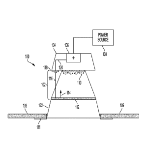
[0009] FIG. 1 depicts a sectional schematic view of a luminaire
including a
lens diffuser selection mechanism, according to certain aspects of the present
disclosure.
[0010] FIG. 2 depicts a schematic view of a room facing (e.g.,
downward
facing) portion of the luminaire of FIG. 1, according to certain aspects of
the present
disclosure.
[0011] FIG. 3 depicts a sectional schematic view of a luminaire that
extends
below a ceiling and includes a lens diffuser selection mechanism, according to
certain
aspects of the present disclosure.
3
Date Recue/Date Received 2020-10-15
[0012] FIG. 4 depicts a flowchart of a process for controlling the
luminaires of
FIGS. 1 and 3 using a lens diffuser selection mechanism, according to certain
aspects of the
present disclosure.
[0013] FIG. 5 depicts an example of state diagram of the luminaires
of FIGS. 1
and 3, according to certain aspects of the present disclosure.
Detailed Description
[0014] The present disclosure relates to systems that that enable
control of
luminaire operations using interactive user interfaces. As explained above,
devices currently
used to control certain types of connected lighting systems may suffer from
accessibility
issues. As a result, access to control of the connected lighting system may be
limited.
[0015] The subject matter of the presently disclosed embodiments is
described
herein with specificity to meet statutory requirements, but this description
is not necessarily
intended to limit the scope of the claims. The claimed subject matter may be
embodied in
other ways, may include different elements or steps, and may be used in
conjunction with
other existing or future technologies. This description should not be
interpreted as implying
any particular order or arrangement among or between various steps or elements
except
when the order of individual steps or arrangement of elements is explicitly
described.
[0016] The presently disclosed subject matter includes a luminaire
with an
internal light output selection mechanism. For example, the luminaire may
include a
mechanism capable of selecting a correlated color temperature (CCT), a light
intensity, an
"on" or "off' state, or a combination thereof using a depression of a lens
diffuser of the
luminaire, using a rotation of a portion of the luminaire, or using a
combination of lens
4
Date Recue/Date Received 2020-10-15
diffuser depression and rotation. For example, upon depressing a lens diffuser
of a
luminaire, the luminaire may enter an "on" state (e.g., generating light
output) from an "off'
state (e.g., not generating light output) or an "off' state from an "on"
state. In another
example, depressing the lens diffuser may change a light intensity output of
the luminaire, or
depressing the lens diffuser may change a CCT of the light output of the
luminaire.
[0017] In another example, the light intensity, the CCT, or both of
the
luminaire may be adjusted by rotating the lens diffuser in a clockwise or
counterclockwise
direction. For example, the lens diffuser may rotate freely within a lens
housing, and a
rotation tracker may adjust the light intensity or CCT based on a detection of
how much the
lens diffuser has rotated. In an additional example, a cone reflector (e.g.,
within a downlight)
may also be rotatable to control output of the light intensity or the CCT of
the luminaire.
[0018] FIG. 1 is a sectional schematic view of a luminaire 100
including a lens
diffuser selection mechanism 102. The luminaire 100 includes a housing 104
with a
controller 106. The controller 106 may be coupled to an external or internal
power source
108, and the controller 106 provides control signals to one or more lighting
devices 110 (e.g.,
light emitting diodes or other light sources). The luminaire 100 may be
installed within a
ceiling 109, and a flange 111 of the luminaire 100 may be positioned flush
with the ceiling
109 such that gaps are avoided between the luminaire 100 and a hole in the
ceiling 109 in
which the luminaire 100 is positioned.
[0019] In an example, the controller 106 controls the light
intensity and the
CCT of the lighting devices 110 based on a user interaction with the lens
diffuser selection
mechanism 102. The lens diffuser selection mechanism 102 may include a lens
diffuser 112
that diffuses light from the lighting devices 110. In an example, a user may
depress a lens
Date Recue/Date Received 2020-10-15
diffuser 112 toward the lighting devices 110. Depression of the lens diffuser
112 exerts a
force in a direction 114 on a selection rod 116 or other actuation device. The
selection rod
116 may depress or otherwise interact with a switching mechanism 118. Based on
the
interaction between the selection rod 116 and the switching mechanism 118, a
control signal
is provided along a control line 120 to the controller 106 to control the
light output of the
lighting devices 110. Other components of the luminaire 100 may also be used
to provide
the force in the direction 114 on the selection rod 116. For example, a cone
reflector 122
may be depressed to interact with a selection rod 116 of the switching
mechanism 118.
[0020]
As discussed above, the depression of the lens diffuser 112 may cause
the controller 106 to control the lighting devices 110 in several different
ways. For example,
each depression of the lens diffuser 112 may result in the transition of the
lighting devices
110 from an "off' state to an "on" state or from an "on" state to an "off'
state. In another
example, each depression of the lens diffuser 112 may cycle through available
light
intensities for the lighting devices 110. For example, a first depression of
the lens diffuser
112 may provide an output light intensity of 100%, a second depression of the
lens diffuser
112 may provide an output light intensity of 75%, a third depression of the
lens diffuser 112
may provide an output light intensity of 50%, and so on. Other transitions
between output
light intensities are also contemplated. In another example, each depression
of the lens
diffuser 112 may cycle through available CCTs of the lighting devices 110. For
example, a
first depression of the lens diffuser 112 may provide an output CCT that
appears "warm,"
while a second depression of the lens diffuser 112 may transition the output
CCT to appear
"cool." Other output CCT transitions are also contemplated.
6
Date Recue/Date Received 2020-10-15
[0021] In another example, the depression of the lens diffuser 112
may send a
control signal along the control line 120 to the controller 106 to transition
the control mode
of the lighting devices 110. For example, a first depression of the lens
diffuser 112 may
transition the lighting devices 110 to an "on" state from an "off' state. A
second depression
of the lens diffuser 112 may transition the lighting devices 110 into a light
intensity control
mode. While the lighting devices 110 are in a light intensity control mode,
the lens diffuser
112 may be rotated (e.g., clockwise or counterclockwise) to provide control
signals to the
controller 106 that control the light intensity of the lighting devices 110.
For example, as the
lens diffuser 112 rotates in a clockwise direction, the light intensity of the
lighting devices
110 may increase. Similarly, as the lens diffuser 112 rotates in a
counterclockwise direction,
the light intensity of the lighting devices 110 may decrease.
[0022] A third depression of the lens diffuser 112 may transition
the lighting
devices 110 into a CCT control mode. While the lighting devices 110 are in the
CCT control
mode, the lens diffuser 112 may be rotated to provide control signals to the
controller 106 to
control the CCT output by the lighting devices 110. For example, as the lens
diffuser 112
rotates in a clockwise direction, the CCT may gradually transition from a
warmer color
temperature to a colder color temperature. Similarly, as the lens diffuser 112
rotates in a
counterclockwise direction, the CCT may gradually transition from a cooler
color
temperature to a warmer color temperature. Further, a fourth depression of the
lens diffuser
112 may transition the lighting devices 110 from the "on" state to the "off'
state.
[0023] The lighting devices 110 may also be controlled by depressing
the lens
diffuser 112 in different manners. For example, depressing the lens diffuser
112 with a
"long" press (e.g., where the lens diffuser 112 is depressed for more than 1
second) may
7
Date Recue/Date Received 2020-10-15
transition the lighting devices into one control mode (e.g., a CCT control
mode or a light
intensity control mode). Additionally, depressing the lens diffuser 112 with a
"short" press
(e.g., where the lens diffuser 112 is depressed for less than or equal to 1
second) may
transition the lighting devices into the other control mode. Further, a series
of "long" presses
may control the lighting devices 110 in a manner different from a series of
"short" presses.
For example, three "long" presses may cycle through color temperature
settings, while three
"short" presses may cycle through light intensity settings. In another
example, combinations
of "long" and "short" presses may change the control mode of the lighting
devices 110. For
example, each control mode may be accessed by a unique combination of the
"long" and
"short" presses on the lens diffuser 112.
[0024]
In another example, the rotational control of the lighting devices 110
may be provided by rotating a cone reflector 122 of the luminaire 100. For
example, the
cone reflector 122 may be rotated in place of the lens diffuser 112 or in
addition to the lens
diffuser 112. For example, upon depressing the lens diffuser 112 to transition
the lighting
devices 110 from the "off' state to the "on" state, the lens diffuser 112 may
be rotated to
control the light intensity of the lighting devices 110, while the cone
reflector 122 may be
rotated to control the CCT of the lighting devices 110. In another example,
the lens diffuser
112 is rotated to control the CCT of the lighting devices 110, while the cone
reflector 112 is
rotated to control the light intensity of the lighting devices 110. Any other
characteristics of
the lighting devices 110 may also be controlled by the depression of the lens
diffuser 112,
rotation of the lens diffuser 112 or other component of the luminaire 100, or
any combination
thereof.
8
Date Recue/Date Received 2020-10-15
[0025] In another example, the depression of the lens diffuser 112
may cycle
through light intensities of the lighting devices 110, while rotation of the
lens diffuser 112 or
the cone reflector 122 provides control of the CCT of the lighting devices
110. Similarly, the
depression of the lens diffuser 112 may cycle through CCT settings of the
lighting devices
110, while the rotation of the lens diffuser 112 provides control of the light
intensity of the
lighting devices 110.
[0026] While the rotational control is generally described herein as
being
provided by rotational movement of the lens diffuser 112 or cone reflector
122, other
components of the luminaire 100 may also be rotated to control the output of
the lighting
devices 110. For example, the flange 111 may also be rotated to provide
control of CCT,
light intensity, or both of the lighting devices 110. Further, other control
mechanisms may
be incorporated into the luminaire 100. For example, a sliding bar may be
installed within
the luminaire 100 to provide control of one or more of the lighting
characteristics of the
lighting devices 110. In an example of a linear luminaire, the lens diffuser
112 may provide
a sliding movement in place of the rotational movement of the lens diffuser
112 described
above.
[0027] FIG. 2 is a schematic view of a room facing (e.g., downward
facing)
portion of the luminaire 100. As discussed above with respect to FIG. 1, any
of the flange
111, the cone reflector 122, and the lens diffuser 112 can be rotated to
control the CCT and
light intensity of the lighting devices 110. Additionally, the luminaire 100
may include a
bezel 202 that is rotatable around the lens diffuser 112. The bezel 202 may
rotate about the
lens diffuser 112 to control characteristics of the lighting devices 110 while
the lens diffuser
9
Date Recue/Date Received 2020-10-15
112 remains stationary. Other lighting control mechanisms may also be
installed with the
luminaire 100 to control lighting characteristics of the lighting devices 110.
[0028] FIG. 3 is a sectional schematic view of a luminaire 300 that
extends
below a ceiling 309 and includes a lens diffuser selection mechanism 302. The
luminaire
300 includes a housing 304 with a controller 306. The controller 306 may be
coupled to an
external or internal power source 308, and the controller 306 provides control
signals to one
or more lighting devices 310 (e.g., light emitting diodes or other light
sources). The
luminaire 300 may be installed within the ceiling 309.
[0029] In an example, the controller 306 controls the light
intensity and the
CCT of the lighting devices 310 based on a user interaction with the lens
diffuser selection
mechanism 302. For example, a user may depress a lens diffuser 312 toward the
lighting
devices 310. Depression of the lens diffuser 312 exerts a force in a direction
314 on a
selection rod 316 or other actuation device. The selection rod 316 depresses
or otherwise
interacts with a switching mechanism 318. Based on the interaction between the
selection
rod 316 and the switching mechanism 318, a control signal is provided along a
control line
320 to the controller 306 to control the light output of the lighting devices
310.
[0030] As discussed above, the depression of the lens diffuser 312
may cause
the controller 306 to control the lighting devices 310 in several different
ways. For example,
each depression of the lens diffuser 312 may result in the transition of the
lighting devices
310 from an "off' state to an "on" state or from an "on" state to an "off'
state. In another
example, each depression of the lens diffuser 312 may cycle through available
light
intensities for the lighting devices 310. For example, a first depression of
the lens diffuser
312 may provide an output light intensity of 100%, a second depression of the
lens diffuser
Date Recue/Date Received 2020-10-15
312 may provide an output light intensity of 75%, a third depression of the
lens diffuser 312
may provide an output light intensity of 50%, and so on. Other transitions
between output
light intensities are also contemplated.
[0031] In another example, each depression of the lens diffuser 312
may cycle
through available CCTs of the lighting devices 310. For example, a first
depression of the
lens diffuser 312 may provide an output CCT that appears "warm," while a
second
depression of the lens diffuser 312 may transition the output CCT to appear
"cool." Other
output CCT transitions are also contemplated.
[0032] In another example, the depression of the lens diffuser 312
may send a
control signal along the control line 320 to the controller 306 to transition
the control mode
of the lighting devices 310. For example, a first depression of the lens
diffuser 312 may
transition the lighting devices 310 to an "on" state from an "off' state. A
second depression
of the lens diffuser 312 may transition the lighting devices 310 into a light
intensity control
mode. While the lighting devices 310 are in the light intensity control mode,
the lens
diffuser 312 may be rotated to provide control signals to the controller 306
to control the
light intensity of the lighting devices 310. For example, as the lens diffuser
312 rotates in a
clockwise direction, the light intensity of the lighting devices 310 may
increase. Similarly,
as the lens diffuser 312 rotates in a counterclockwise direction, the light
intensity of the
lighting devices 310 may decrease.
[0033] A third depression of the lens diffuser 312 may transition
the lighting
devices 310 into a CCT control mode. While the lighting devices 310 are in the
CCT control
mode, the lens diffuser 312 may be rotated to provide control signals to the
controller 306 to
control the CCT output by the lighting devices 310. For example, as the lens
diffuser 312
11
Date Recue/Date Received 2020-10-15
rotates in a clockwise direction, the CCT may gradually transition from a
warmer color
temperature to a colder color temperature. Similarly, as the lens diffuser 312
rotates in a
counterclockwise direction, the CCT may gradually transition from a colder
color
temperature to a warmer color temperature. Further, a fourth depression of the
lens diffuser
312 may transition the lighting devices 310 from the "on" state to the "off'
state.
[0034] In another example, the rotational control of the lighting
devices 310
may be provided by rotating the housing 304 of the luminaire 100. For example,
the housing
304 may be rotated in place of the lens diffuser 312 or in addition to the
lens diffuser 312. In
an example, upon depressing the lens diffuser 312 to transition the lighting
devices 310 from
the "off' state to the "on" state, the lens diffuser 312 may be rotated to
control the light
intensity of the lighting devices 310, while the housing 304 may be rotated to
control the
CCT of the lighting devices 310. In another example, the lens diffuser 312 is
rotated to
control the CCT of the lighting devices 310, while the housing 304 is rotated
to control the
light intensity of the lighting devices 310.
[0035] In other examples, the depression of the lens diffuser 312
may cycle
through light intensities of the lighting devices 310, while rotation of the
lens diffuser 312 or
the housing 304 provides control of the CCT of the lighting devices 310.
Similarly, the
depression of the lens diffuser 312 may cycle through CCT settings of the
lighting devices
310, while the rotation of the lens diffuser 312 provides control of the light
intensity of the
lighting devices 310.
[0036] While the rotational control is generally described herein as
being
provided by rotational movement of the lens diffuser 312 or the housing 304,
other
components of the luminaire 300 may also be rotated to control the output of
the lighting
12
Date Recue/Date Received 2020-10-15
devices 310. For example, other control mechanisms may also be incorporated
into the
luminaire 300 such as a diffuser lens bezel or other rotating component
capable of providing
control for one or more of the lighting characteristics of the lighting
devices 310.
[0037] FIG. 4 is a flowchart of a process 400 for controlling the
luminaire 100
using a lens diffuser selection mechanism 102. While the process 400 is
described with
respect to the luminaire 100 depicted in FIG. 1, the process 400 may also
apply to the
luminaire 300 depicted in FIG. 3. At block 402, the process 400 involves
receiving a
selection from the lens diffuser 112 to transition a state of the luminaire.
In some examples,
the selection may involve a user depressing the lens diffuser 112 to
transition the state of the
luminaire to a correlated color temperature (CCT) control state, a light
intensity control state,
an "on- or "off' state, or a combination thereof.
[0038] At block 404, the process 400 involves receiving a rotational
input at
the luminaire 100 to adjust the lumen output or the CCT output of the
luminaire 100. The
rotational input may be provided by rotation of the lens diffuser 112 or any
other rotational
elements of the luminaire 100, as described above with respect to FIGS. 1-3.
In another
example, the lens diffuser 112 may be rotated to control the CCT output of the
luminaire
100, while an additional rotational element of the luminaire 100 (e.g., the
cone reflector 122,
the bezel 202, the flange 111, the housing 304, etc.) is rotated to control
the light intensity of
the luminaire 100. Moreover, any combination rotational elements of the
luminaire 100 may
be used for controlling the CCT output and the light intensity of the
luminaire 100.
[0039] At block 406, the process 400 involves receiving a selection
from the
lens diffuser 112 to transition the luminaire 100 to an additional state of
the luminaire 100.
In an example, the luminaire 100 may transition from the CCT control state to
the light
13
Date Recue/Date Received 2020-10-15
intensity control state. In such an example, the process 400 may return to
block 404 to
receive another rotational input at the luminaire 100 to control the light
intensity of the
luminaire 100. In an additional example, the luminaire 100 may transition to
the "off' state
upon receiving the selection at block 406.
[0040] FIG. 5 depicts an example of state diagram 500 of the
luminaires 100
and 300, according to certain aspects of the present disclosure. While the
state diagram 500
depicts an OFF state 502 as an initial state, any of the described states may
be the initial state
of the luminaires 100 and 300. Further, the states depicted in the state
diagram 500 may
occur in any order. As shown, the OFF state 502 may be when the luminaires 100
and 300
are not generating a light output. After receiving an input from the lens
diffuser selection
mechanism 102, the luminaires 100 and 300 may transition to an ON state 504.
The ON
state 504 may be when the luminaires 100 and 300 output a light. The light
output when
transitioning to the ON state 504 may be a pre-determined light output (e.g.,
a pre-
determined light intensity and CCT), or the light output may be a most recent
light output
prior to the luminaires 100 and 300 entering the OFF state 502.
[0041] Upon receiving another input from the lens diffuser selection
mechanism 102, the luminaires 100 and 300 may transition to a light intensity
control state
506. In the light intensity control state 506, the luminaires 100 and 300 may
receive a
rotational input from a rotational element of the luminaires 100 and 300 to
control the light
intensity of the light output from the luminaires 100 and 300. The rotational
input in a
clockwise direction may increase the light intensity, while the rotational
input in the
counterclockwise direction may decrease the light intensity of the luminaires
100 and 300.
14
Date Recue/Date Received 2020-10-15
[0042] Upon receiving another input from the lens diffuser selection
mechanism 102, the luminaires 100 and 300 may transition to a correlated color
temperature
(CCT) control state 508. In the CCT control state 508, the luminaires 100 and
300 may
receive a rotational input from a rotational element of the luminaires 100 and
300 to control
the color temperature of the light output from the luminaires 100 and 300. The
rotational
input in a clockwise direction may increase the coolness of the color
temperature of the light
output, while the rotational input in the counterclockwise direction may
increase a warmth of
the color temperature of the light output of the luminaires 100 and 300. Upon
receiving
another input from the lens diffuser selection mechanism 102, the luminaires
100 and 300
may transition to the OFF state 502.
[0043] In an example, the transition from the OFF state 502 to the
ON state
504 may transition the luminaires 100 and 300 directly to the light intensity
control state 506
or the CCT control state 508 without an additional input after transitioning
to the ON state
504. Further, the transitions to the light intensity control state 506 and the
CCT control state
508 may occur simultaneously when the luminaires 100 and 300 have multiple
rotational
elements that can receive a rotational input. For example, the lens diffuser
112 can receive a
rotational input to control the light intensity while the cone reflector 122
can receive a
rotational input to control the CCT of the light output. That is, one
rotational element may
be assigned to light intensity control while another rotational element may be
assigned to
CCT control of the luminaires 100 and 300.
[0044] The foregoing is provided for purposes of illustrating,
explaining, and
describing various embodiments. Having described these embodiments, it will be
recognized
by those of skill in the art that various modifications, alternative
constructions, and
Date Recue/Date Received 2020-10-15
equivalents may be used without departing from the spirit of what is
disclosed. Different
arrangements of the components depicted in the drawings or described above, as
well as
additional components and steps not shown or described, are possible. Certain
features and
subcombinations of features disclosed herein are useful and may be employed
without
reference to other features and subcombinations. Additionally, a number of
well-known
processes and elements have not been described in order to avoid unnecessarily
obscuring
the embodiments. Embodiments have been described for illustrative and not
restrictive
purposes, and alternative embodiments will become apparent to readers of this
patent.
Accordingly, embodiments are not limited to those described above or depicted
in the
drawings, and various modifications can be made without departing from the
scope of the
presently disclosed subject matter.
16
Date Recue/Date Received 2020-10-15