Note: Descriptions are shown in the official language in which they were submitted.
CABLE CONVEYANCE SYSTEMS INCORPORATING
ELECTRONIC VISUAL DISPLAYS
BACKGROUND
Technical Field
[0001] The present disclosure relates to cable conveyance. More
particularly, the
present disclosure relates to cable conveyance systems incorporating
electronic visual
displays to utilize cable conveyance structures for the display of relevant
information,
advertisements, etc.
Background of Related Art
[0002] Cable conveyance of power, communication, data and/or other cabling
is
utilized in almost all modern infrastructure including office and industrial
buildings,
transportation structures such as railways and subways, stadiums and other
entertainment venues, etc.
[0003] In some instances, whether by choice, out of convenience, or out of
necessity, cables extend through open areas thereby rendering the cables
and/or cable
conveyance structures supporting the cables visible to the public, customers,
visitors,
occupants, etc.
SUMMARY
[0004] Provided in accordance with the present disclosure are cable
conveyance
systems incorporating electronic visual displays. In the manner, cable
conveyance
structures visible to the public, customers, visitors, occupants, etc., can be
utilized for
the display of relevant information, advertisements, etc. For example, the
electronic
- 1 -
Date Recue/Date Received 2020-10-20
visual displays of cable conveyance structures extending through a subway
station may
be utilized to display train information, updates and alerts, advertisements,
public
service announcements, etc. The above and other aspects and features of the
present
disclosure are detailed below. To the extent consistent, any of the aspects
and features
detailed herein may be utilized with any or all of the other aspects and
features detailed
herein.
[0005] In accordance with aspects of the present disclosure, a cable
conveyance
system is provided including first and second rails extending longitudinally
in spaced-
apart relation relative to one another, a plurality of cable-retaining
supports disposed
between the first and second rails, and at least one front panel including an
electronic
visual display. Each cable-retaining support is configured to retain at least
one
longitudinally-extending cable therein. The at least one front panel is
hingedly coupled
to the first rail such that the at least one first panel is pivotable relative
to the first and
second rails between an open position, providing access to the plurality of
cable-
retaining supports, and a closed position, at least partially enclosing the
plurality of
cable-retaining supports between the first and second rails and the at least
one front
panel.
[0006] In aspects of the present disclosure, the cable conveyance system
further
includes a back panel extending between the first and second rails and
longitudinally
therealong. The plurality of cable-retaining supports are disposed on the back
panel.
[0007] In aspects of the present disclosure, the first and second rails
extend
generally perpendicularly from the back panel and, in the closed position, the
at least
- 2 -
Date Recue/Date Received 2020-10-20
one front panel extends generally parallel to the back panel to define a
rectangular
cross-sectioned enclosure.
[0008] In aspects of the present disclosure, the at least one front panel
includes a
plurality of front panels each including an electronic visual display. Each
front panel
may independently pivot relative to the other front panels of the plurality of
front panels.
Additionally or alternatively, the electronic visual displays of the front
panels may be
configured to cooperate to define an elongate display and/or may be configured
as
independent displays.
[0009] In aspects of the present disclosure, the plurality of cable-
retaining supports
includes at least one elongated spine including a plurality of support members
depending therefrom to define a longitudinal cable-receiving passage. In such
aspects,
the at least one elongated spine and the plurality of support members are each
formed
from wire stock.
[0010] In aspects of the present disclosure, the first and second rails are
upper and
lower rails, respectively.
BRIEF DESCRIPTION OF THE DRAWINGS
[0011] Various aspects and features of the present disclosure are described
hereinbelow with reference to the drawing figures, wherein:
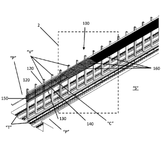
[0012] FIG. 1 is a perspective view of a cable conveyance system provided
in
accordance with the present disclosure shown extending through a subway
station;
[0013] FIG. 2 is an enlarged, perspective view of the area of detail
identified as "2" in
FIG. 1;
- 3 -
Date Recue/Date Received 2020-10-20
[0014]
FIG. 3A is a transverse, cross-sectional view taken across section line "3A-
3A" of FIG. 2, wherein a front panel of the cable conveyance system is
disposed in an
open position; and
[0015]
FIG. 3B is a transverse, cross-sectional view as illustrated in FIG. 3A,
wherein
the front panel of the cable conveyance system is disposed in a closed
position.
DETAILED DESCRIPTION
[0016]
Referring generally to FIGS. 1-3B, a cable conveyance system provided in
accordance with the present disclosure is shown generally identified by
reference
numeral 100. Although detailed and illustrated herein extending through a
subway
station "5" and supported on vertical beams "V" arranged between different
sets of train
tracks "T," cable conveyance system 100 is equally applicable for use in other
industries
and/or for support from different support structures.
Further, while one cable
conveyance system 100 is shown oriented towards one platform "P" serving one
set of
train tracks "T" of the subway station "5," it is contemplated that a second
cable
conveyance system 100 may be provided on the opposite side, e.g., oriented
towards
the other platform "P" serving the other set of train tracks "T" of the subway
station "S."
[0017]
Cable conveyance system 100 includes one or more upper rails 120, one or
more lower rails 130, and one or more cable-retaining supports 140. The one or
more
upper rails 120 are arranged end-to-end so as to collectively define an
elongated upper
rail 120. As such, the one or more upper rails 120 will be referred to in the
singular with
the understanding that the upper rail 120 may include plural upper rails 120.
Likewise,
the one or more lower rails 130 are arranged end-to-end so as to collectively
define an
elongated lower rail 130. As such, the one or more lower rails 130 will be
referred to in
- 4 -
Date Recue/Date Received 2020-10-20
the singular with the understanding that the lower rail 130 may include plural
lower rails
130.
[0018] In embodiments, cable conveyance system 100 further includes one or
more
back supports 150 extending between and interconnecting upper and lower rails
120,
130. The one or more back supports 150 are arranged end-to-end so as to
collectively
define an elongated back support. As such, the one or more back supports 150
will be
referred to in the singular with the understanding that the back support 150
may include
plural back supports 150.
[0019] Upper and lower rails 120, 130 are oriented substantially
perpendicular (e.g.,
within 15 of perpendicular) relative to back support 150 such that upper and
lower rails
120, 130 extend outwardly from back support 150. Back support 150 may be
configured as a solid panel, a mesh or otherwise partially-open panel, an
arrangement
of vertical and/or horizontal bars, or other suitable configuration. In other
embodiments,
back support 150 is omitted. Back support 150 may be attached to vertical
beams "V,"
e.g., via bolts, to support cable conveyance system 100 therefrom.
Alternatively or
additionally, upper and/or lower rails 120, 130 may be attached to vertical
beams "V,"
e.g., via bolts, to support cable conveyance system 100 therefrom. As an
alternative to
support via vertical beams "V," cable conveyance system 100 may be supported
on one
or more horizontal surfaces, may be engaged with one or more horizontal
structures,
may depend from one or more overhead structures, or may be supported in any
other
suitable configuration including combinations of the above or other
configurations.
[0020] Cable-retaining supports 140 may be integrally formed with or
otherwise
attached to back support 150, e.g., via welding, bolts, etc. In embodiments
where back
- 5 -
Date Recue/Date Received 2020-10-20
support 150 is omitted, cable-retaining supports 140 may also serve to
interconnect
upper and lower rails 120, 130, although cable-retaining supports 140 may
alternatively
be independent of upper and/or lower rails 120, 130. Plural cable-retaining
supports 140
may be arranged in end-to end fashion to define an elongated cable-retaining
support.
Alternatively or additionally, cable-retaining supports 140 may be arranged in
one or
more vertically-spaced, horizontally-extending rows (see FIGS. 3A and 3B).
[0021] Cable-retaining supports 140 may include one or more pluralities of
individual
support members 142 wherein the individual support members 142 of each
plurality of
support members 142 are arranged to define a longitudinally-extending
passageway
144 therethrough. Alternatively or additionally, one or more of the cable-
retaining
supports 140 may include a plurality of support members 142 spaced-apart along
and
connected to a flexible spine 146. Support members 142 and/or flexible spines
146, in
any of the above-embodiments, may be formed from wire stock and/or may be
welded
to one another. Support members 142 may be configured to define suitable
curvature,
angles, etc. such that longitudinally-extending passageways 144 define any
suitable
cross-sectional configuration, e.g., circular, oval, polygonal, irregular,
etc., and may be
configured to define multiple areas within longitudinally-extending
passageways 144 to
enable separation of some cables "C" from other cables "C." Flexible spines
146 may
be configured to bend off of a longitudinal axis thereof to enable routing
above, below,
or around obstacles or for other purposes.
[0022] In embodiments, as an alternative or in addition to individual
support member
142, e.g., formed from wire stock, cable-retaining supports 140 may include
one or
more longitudinally-extending support troughs (not shown) or other suitable
cable-
- 6 -
Date Recue/Date Received 2020-10-20
supporting structures.
Regardless of the particular configuration, cable-retaining
supports 140 are configured to retain a plurality of cables "C" therein, thus
enabling
longitudinal conveyance of cables "C" along cable conveyance system 100.
Further,
cable-retaining supports 140 extend outwardly from back support 150 to define
a depth
dimension that is less than a depth dimension of upper and lower rails 120,
130. That
is, upper and lower rails 120, 130 protrude further outwardly from back
support 150 as
compared to cable-retaining supports 140. In embodiments, cable-retaining
supports
140 may be mounted on back support 150, e.g., via bolts, and/or may be
attached to
vertical beams "V," e.g., via bolts.
[0023]
Cable conveyance system 100 further includes one or more front panels 160
including an electronic visual display. The one or more front panels 160 are
arranged
end-to-end so as to collectively define an elongated front panel. Each
electronic visual
display may be, e.g., an electroluminescent display (ELD), a liquid crystal
display (LCD),
a light-emitting diode (LED) display, an organic light-emitting diode (OLED)
display, a
plasma display (PD), or other suitable electronic visual display. The
electronic visual
displays, in embodiments where plural front panels 160 are provided, may be
configured to operate independently of one another as separate displays,
and/or may
be configured to operate collectively with one or more other, e.g., adjacent,
displays to
define an extended display.
[0024]
In some embodiments of cable conveyance system 100, one or more
electronic visual display front panels 160 are provided in addition to one or
more
standard front panels 160, e.g., panels formed from a sheet or other piece(s)
of
- 7 -
Date Recue/Date Received 2020-10-20
material. Alternatively or additionally, a portion or portions of cable
conveyance system
100 may omit front panels 160.
[0025] With particular reference to FIGS. 3A and 3B, each front panel 160
is coupled
to upper rail 120 via one or more hinges 170 to enable the front panel 160 to
pivot
between an open position (FIG. 3A), wherein the front panel 160 is disposed at
an angle
relative to back panel 150 and cable-retaining supports 140 are at least
partially
exposed, and a closed position (FIG. 3B), wherein the front panel 160 is
disposed in
substantially parallel (e.g., within 15 of parallel) orientation relative to
back panel 150 to
define an enclosure with back panel 150, upper rail 120, and lower rail 130
that
encloses cable-retaining supports 140 therein. Alternatively or additionally,
one or more
front panels 160 may be hingedly engaged to lower rail 130 and/or one or more
front
panels 160 may be fixedly engaged to upper rail 120 and/or lower rail 130. In
embodiments, releasable locking structure(s) may be provide to enable
releasable
locking of front panel(s) 160 with lower rail 130 in the closed position.
Allowing front
panels 160 to pivot about hinges 170 between the open position and the closed
position
allows for access to cable-retaining supports 140, e.g., to lay, remove,
and/or rearrange
cables "C."
[0026] Due to the fact that upper and lower rails 120, 130 protrude further
outwardly
from back support 150 as compared to cable-retaining supports 140, front
panels 160,
in the closed position (FIG. 3B), do not interfere with cable-retaining
supports 140 or the
cables "C" conveyed therealong. Rather, front panels 160 close and form the
enclosure retaining cable-retaining supports 140 and cables "C" therein.
Further,
display cabling "D" connected to the electronic visual display front panels
160 may be
- 8 -
Date Recue/Date Received 2020-10-20
routed into one of the cable-retaining supports 140 for conveyance at least
partially
along cable conveyance system 100, e.g., to a power supply, router, computer,
other
communication device, etc., for powering, controlling, and/or communicating
with
electronic visual display front panels 160.
[0027] Referring again to FIGS. 1-3B, electronic visual display front
panels 160 may
be configured to display, for example, textual information, still graphics,
animated
graphics, video, combinations thereof, etc. With respect to implementation in
subway
station "5," for example, the textual information may include train status
information,
changes, alerts, warnings, updates, etc. The graphics and video may include
public
service announcements, advertisements, notifications, etc. Depending on the
desired
configuration, one or more electronic visual display front panels 160 may be
independent of or work in cooperation with one or more other electronic visual
display
front panels 160 such that, for example, a portion or portions of cable
conveyance
system 100 may display train status information across one or more other
electronic
visual display front panels 160 and another portion or portions of cable
conveyance
system 100 may display advertisements, public service announcements, etc.
[0028] Regardless of the particular information provided via electronic
visual display
front panels 160, by positioning cable conveyance system 100 in a suitable
position,
e.g., supported on vertical beams "V" arranged between different sets of train
tracks "T"
and facing a platform "P" in a subway station "5," cable conveyance system 100
becomes a desirable, information-providing utility in addition to its use to
convey and
conceal cable-retaining supports 140 and cables "C." That is, rather than
attempting to
hide cables "C" and/or cable conveyance system 100 from view, cable conveyance
- 9 -
Date Recue/Date Received 2020-10-20
system 100 is prominently positioned to provide visual information, e.g.,
advertisements,
status information, weather, news, updates, alerts, notifications, etc., in an
attractive
and useful manner.
[0029] Portions of cable conveyance system 100 not visible, e.g., portions
within
subway tunnels, on the other hand, may include standard front panels 160, no
front
panels 160, or may exclude enclosures altogether, e.g., wherein just cable-
retaining
supports 140 (or other cable-conveying structures) are provided for conveying
cables
"C..
[0030] From the foregoing and with reference to the various figure
drawings, those
skilled in the art will appreciate that certain modifications can also be made
to the
present disclosure without departing from the scope of the same. While several
embodiments of the disclosure have been shown in the drawings, it is not
intended that
the disclosure be limited thereto, as it is intended that the disclosure be as
broad in
scope as the art will allow and that the specification be read likewise.
Therefore, the
above description should not be construed as limiting, but merely as
exemplifications of
particular embodiments. Those skilled in the art will envision other
modifications within
the scope and spirit of the claims appended hereto.
- 10 -
Date Recue/Date Received 2020-10-20