Note: Descriptions are shown in the official language in which they were submitted.
CA 03097026 2020-10-14
WO 2019/204910 PCT/CA2019/050497
TITLE: CONE FILLING APPARATUS AND RELATED METHODS
CROSS-REFERENCE TO RELATED APPLICATIONS
This application is based on and claims priority to U.S. Provisional
Application
Serial No. 62/661,348 filed April 23, 2018, U.S. Provisional Application
Serial No.
62/809,998 filed February 25, 2019, U.S. Provisional Application Serial No.
62/810,010 filed February 25, 2019, and U.S. Provisional Application Serial
No.
62/810,017 filed February 25, 2019 and titled Compaction Apparatus and
Related Methods, each of which is incorporated herein by reference in its
entirety.
FIELD
[0001] The specification relates generally to production of smoking articles,
and
more specifically, to apparatuses and methods for filling cones in production
of
conical smoking articles.
BACKGROUND
[0002] Int. Pub. No. WO 2017/172844 Al discloses an apparatus including a
holder plate and a carriage assembly. The holder plate includes a plurality of
through-holes configured to receive containers having an interior cavity. The
carriage assembly comprises one or more carriage plates and tamper rods, the
carriage plates having a plurality of through-holes. Each of the tamper rods
can
be slidably disposed in a respective one of the plurality of through-holes of
the
carriage plate. Each of the tamper rods can be independently weighted to
provide a force independent of the other of the tamper rods and can be
independently movable relative to the other of the tamper rods. The carriage
assembly can be configured to be aligned with the holder plate such that the
each of the tamper rods provides a compressive force to a filler material
within
the interior cavity of each of the containers.
1
CA 03097026 2020-10-14
WO 2019/204910 PCT/CA2019/050497
[0003] U.S. Pat. App. Pub. No. 2016/0120212 Al discloses a tube filling
apparatus. The apparatus includes a base and a filling assembly mountable on
the base. The filling assembly has a number of tube receiving recesses wherein
tubes may, in use, be received. The apparatus further includes a vibration
plate
which is locatable between the base and the filling assembly. In use, the
tubes
rest on the vibration plate when they are located in the recesses. The
apparatus
also includes vibrating means which is connected to the vibration plate for,
in
use, vibrating the vibration plate, which is capable of moving independently
from
the filling assembly.
SUMMARY
[0004] The following summary is intended to introduce the reader to various
aspects of the applicant's teaching, but not to define any invention.
[0005] According to some aspects, a cone filling apparatus for production of
smoking articles includes: (a) a cone pallet including a plurality of
cavities, each
cavity for holding a respective cone; (b) a delivery chute having a load end
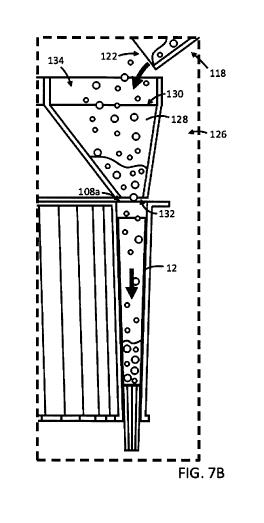
for
receiving a smokeable product from a source and an unload end downstream of
the load end for unloading the smokeable product from the chute; and (c) a
dosing tray disposed above the pallet. The dosing tray includes a plurality of
transfer sleeves. Each sleeve has an upper sleeve end for receiving smokeable
product unloaded from the unload end of the chute, and a lower sleeve end for
dispensing the smokeable product into a cone held in a respective cavity
aligned
beneath the lower sleeve end.
[0006] In some examples, the chute is configured to provide a controlled flow
of
the smokeable product to the dosing tray.
[0007] In some examples, chute includes an inner chute surface for conveying
the smokeable product, and a plurality of prongs adjacent the inner chute
surface
for inhibiting consolidation of the smokeable product.
2
CA 03097026 2020-10-14
WO 2019/204910 PCT/CA2019/050497
[0008] In some examples, the load end is at an elevation greater than the
unload end to facilitate transport of smokeable product along the chute by
gravitational force.
[0009] In some examples, the chute includes at least a first chute segment and
a second chute segment downstream of the first chute segment. The first chute
segment includes the load end and the second chute segment includes the
unload end. In some examples, the chute includes a third chute segment
intermediate the first chute segment and the second chute segment. The third
chute segment has a third segment upstream end for receiving product from the
first chute segment and a third segment downstream end for delivering product
to
the second chute segment. In some examples, one of the chute segments is
inclined at a first angle from the horizontal and another one of the chute
segments is inclined at a second angle from the horizontal. The second angle
is
different from the first angle.
[0010] In some examples, the chute is sized to receive one batch amount of the
smokeable product. The batch amount is equal to an amount of product required
to fill all the cones in the cone pallet.
[0011] In some examples, the chute is configured to preferentially advance
product granules by size. In some examples, the chute is configured to advance
larger granules ahead of smaller granules.
[0012] In some examples, the apparatus includes a vibratory drive operable to
urge vibration of the chute. In some examples, the vibratory drive has an
adjustable frequency and amplitude. The frequency and amplitude are tunable to
facilitate a desired flow rate and preferential advancement of the smokeable
product based on granule size along the chute.
[0013] In some examples, the plurality of transfer sleeves and the plurality
of
cavities are of equal quantity.
[0014] In some examples, the dosing tray includes a collection chamber above
3
CA 03097026 2020-10-14
WO 2019/204910 PCT/CA2019/050497
the transfer sleeves for receiving the product from the unload end of the
chute
and facilitating dispersion of the product among the transfer sleeves.
[0015] In some examples, the lower ends of the transfer sleeves are
simultaneously aligned with open upper ends of the respective cavities.
[0016] In some examples, each of the plurality of cavities and the plurality
of
transfer sleeves are arranged about a vertical axis in a circular array, and
the
apparatus includes a rotary drive for rotating the dosing tray about the
vertical
axis. In some examples, the cone pallet is releasably coupled to the dosing
tray
to rotate with the dosing tray and maintain alignment of the transfer sleeves
and
the cavities. In some examples, rotation of the dosing tray is synchronized
with a
rate at which product is dispensed from the unload end of the chute such that
the
dosing tray rotates an integer multiple of times while receiving one batch of
the
smokeable product from the unload end. The one batch is equal to an amount of
product required to fill all the cones in the cone pallet.
[0017] According to some aspects, a method of production of smoking articles
includes: (a) positioning a plurality of cones in respective cavities of a
cone pallet;
(b) positioning the cone pallet under a dosing tray; (c) conveying a smokeable
product along a chute toward an unload end of the chute, the unload end
positioned above the dosing tray; and (d) unloading the smokeable product from
the unload end of the chute and into the cones through a plurality of transfer
sleeves of the dosing tray.
[0018] In some examples, step (c) includes controllably flowing the smokeable
product along the chute to the unload end.
[0019] In some examples, step (c) includes conveying the smokeable product
along the chute at least in part by gravitational force.
[0020] In some examples, the method further includes loading the chute with
one batch amount of the smokeable product and unloading the batch amount
from the unload end in step (d) prior to loading a subsequent batch amount on
4
CA 03097026 2020-10-14
WO 2019/204910 PCT/CA2019/050497
the chute. The batch amount is equal to an amount of smokeable product
required to fill all the cones in the cone pallet.
[0021] In some examples, step (c) includes preferentially advancing granules
of
the smokeable product based on granule size. In some examples, step (c)
includes advancing larger granules ahead of smaller granules. In some
examples, step (c) includes imparting vibrations on the chute. In some
examples,
the method further includes adjusting at least one of an amplitude and a
frequency of the vibrations to facilitate a desired flow rate and preferential
advancement of the smokeable product based on granule size.
[0022] In some examples, step (c) includes conveying the smokeable product
along a plurality of chute segments of the chute, and the method further
includes
vibrating a first one of the chute segments at a first frequency and a first
amplitude, and vibrating a second one of the chute segments at a second
frequency and a second amplitude. In some examples, at least one of (i) the
second frequency is different from the first frequency and (ii) the second
amplitude is different from the first amplitude.
[0023] In some examples, each of the cavities and the transfer sleeves are
arranged about a vertical axis in a circular array, and the method further
includes,
during step (d), rotating the dosing tray and the cavity pallet about the
vertical
axis to facilitate generally equal dispersion of the smokeable product among
the
cavities.
[0024] In some examples, the method further includes synchronizing rotation of
the dosing tray and the cavity pallet with a rate at which the smokeable
product is
unloaded from the chute such that the dosing tray rotates an integer multiple
of
times while receiving one batch amount of the smokeable product from the
unload end of the chute. The batch amount is equal to an amount of smokeable
product required to fill all the cones in the cone pallet.
[0025] In some examples, step (d) includes: (i) partially filling the first
cone with
5
CA 03097026 2020-10-14
WO 2019/204910 PCT/CA2019/050497
a first amount of the smokeable product, (ii), after (i), partially filling a
second
cone with the smokeable product, and (iii), after (ii), depositing a second
amount
of the smokeable product into the first cone on top of the first amount.
[0026] In some examples, the first amount of the smokeable product has a first
average granule size, and the second amount of the smokeable product has a
second average granule size. The second average granule size is smaller than
the first average granule size.
[0027] In some examples, the method further includes, after step (d),
compacting the smokeable product in the cones. In some examples, the method
further includes, prior to the compacting step, moving the cone pallet from
under
the dosing tray to a compaction station.
[0028] In some examples, the method further includes, after step (d), twisting
an upper portion of each cone to close the cones. In some examples, the method
further includes, prior to the twisting step, moving the cone pallet to a cone
closure station.
BRIEF DESCRIPTION OF THE DRAWINGS
[0029] The drawings included herewith are for illustrating various examples of
articles, methods, and apparatuses of the present specification and are not
intended to limit the scope of what is taught in any way. In the drawings:
[0030] Figure 1 is a perspective view of an example conical smoking article;
[0031] Figure 2 is a perspective view of an example cone for manufacture of
the
smoking article of Figure 1;
[0032] Figure 2A is a cross-sectional view of the cone of Figure 2, taken
along
line 2A-2A of Figure 2;
[0033] Figure 3 is a flow chart showing an example process for production of
conical smoking articles like that of Figure 1;
6
CA 03097026 2020-10-14
WO 2019/204910 PCT/CA2019/050497
[0034] Figure 4 is a schematic elevation view of an example cone filling
apparatus for use with the process of Figure 3;
[0035] Figure 5 is a perspective view of a dosing portion of the apparatus of
Figure 4;
[0036] Figure 6 is a partially exploded view of the dosing portion of Figure
5;
[0037] Figure 7 is a cross-sectional view of the dosing portion of Figure 5,
taken
along line 7-7 of Figure 5;
[0038] Figure 7A is a schematic cross-sectional representation of a portion of
Figure 7, showing pallet and tray portions of the apparatus of Figure 4;
[0039] Figure 7B is a schematic representation like that of Figure 7A, but
showing a cone received in the pallet portion and being filled with a
smokeable
product;
[0040] Figure 8 is a schematic elevation view of chute segments of the
apparatus of Figure 4;
[0041] Figure 8A is a schematic elevation view of one of the chute segments of
Figure 8, shown in a declined position;
[0042] Figure 9 is a partially exploded view of a chute segment of the
apparatus
of Figure 4;
[0043] Figure 10 is a flow chart showing an example process for production of
conical smoking articles using an apparatus like that of Figure 4;
[0044] Figure 11 is a perspective view of another example cone filling
apparatus;
[0045] Figure 12 is an exploded view of a dosing portion of the apparatus of
Figure 11; and
[0046] Figure 13 is a cross-sectional view of the dosing portion of Figure 12,
taken along line 13-13 of Figure 11.
7
CA 03097026 2020-10-14
WO 2019/204910 PCT/CA2019/050497
DETAILED DESCRIPTION
[0047] Various apparatuses or processes will be described below to provide an
example of an embodiment of each claimed invention. No embodiment described
below limits any claimed invention and any claimed invention may cover
processes or apparatuses that differ from those described below. The claimed
inventions are not limited to apparatuses or processes having all of the
features
of any one apparatus or process described below or to features common to
multiple or all of the apparatuses described below. It is possible that an
apparatus or process described below is not an embodiment of any claimed
invention. Any invention disclosed in an apparatus or process described below
that is not claimed in this document may be the subject matter of another
protective instrument, for example, a continuing patent application, and the
applicants, inventors, or owners do not intend to abandon, disclaim, or
dedicate
to the public any such invention by its disclosure in this document.
[0048] Smoking articles having a conical shape, like that of the example
smoking article 10 shown in Figure 1, are popular among a variety of users,
including, for example, cannabis users. Smoking articles having a conical
shape
are typically hand-made, or otherwise produced in small, labor-intensive
batches.
In contrast, cylindrical smoking articles, such as traditional tobacco
cigarettes,
are often manufactured in high volume production systems with a high degree of
sophisticated automation. But the difference in shape, among other reasons,
can
render the processes and apparatus of such automated systems inapplicable to
conically shaped smoking articles such as the article 10.
[0049] Referring to Figures 1 and 2, in the example illustrated, the example
smoking article 10 is formed using a cone 12. The cone 12 is formed of a
smokeable wrapper 16 having a cone cavity 18 for receiving and containing a
smokeable product. In the example illustrated, the wrapper 16 is generally air
impermeable, and the smokeable product is a granular product. In some
8
CA 03097026 2020-10-14
WO 2019/204910 PCT/CA2019/050497
examples, the cone 12 can be preassembled and the cone cavity 18 can be
subsequently filled with the smokeable product. The smokeable product can be
prepared via chopping, grinding, and/or sifting of a bulk smoking material.
The
bulk smoking material can include, for example, dried cannabis plant material,
and the smokeable product can include cannabis granules. The smokeable
product can include a mix of cannabis types or strains. The smokeable can
include a mix of different types of smokeable products such as cannabis and
tobacco.
[0050] Referring to Figure 2A, in the example illustrated, the cone cavity 18
extends along a cone cavity axis 20 between an upper end 22 and a lower end
24 opposite the upper end 22. In the example illustrated, the wrapper 16 has
an
upper end diameter 22a at the upper end 22 of the cavity 18 and a lower end
diameter 24a at the lower end 24 of the cavity 18. The lower end diameter 24a
is
smaller than the upper end diameter 22a, and the wrapper 16 tapers radially
inwardly along the cavity axis 20 from the upper end diameter 22a to the lower
end diameter 24a to provide the cone 12 with a generally conical shape. In the
example illustrated in Figure 2A, the upper end 22 of the cavity 18 is open
for
permitting filling of the cavity 18 with the smokeable product. In the example
illustrated, the cone 12 includes a filter 26 in the cavity 18 adjacent the
lower end
24. The filter 26 can help to provide structural stability to the smoking
article 10,
and can help inhibit smokeable product in the cavity 18 from escaping through
the lower end 24.
[0051] Referring to Figure 3, an example process 50 for production of conical
smoking articles is shown, and will be described with respect to the example
smoking article 10.
[0052] At step 55 of the process 50, a plurality of the cones 12 are staged
for
filling with the smokeable product. The cones 12 can be staged by, for
example,
being positioned in a pallet with the open upper ends 22 directed upwardly for
receiving the smokeable product.
9
CA 03097026 2020-10-14
WO 2019/204910 PCT/CA2019/050497
[0053] At step 60, the staged cones 12 can be filled with the smokeable
product
through respective open upper ends 22 of each cone 12. The cones 12 can be
filled while held in the pallet. The cones 12 can be filled with the smokeable
product using filling apparatuses and methods like those described in more
detail
below with respect to Figures 4 to 13.
[0054] At step 65, the smokeable product in the cones 12 is compacted. The
smokeable product can be compacted while the cones 12 are held in the pallet.
Compaction can be through the means of vibration energy transferred to the
fill
material in the cones. Compaction can be through the use of mechanical devices
acting on the fill material in the cone.
[0055] At step 70, in the example illustrated, an upper portion 28 of each
wrapper 16 is twisted to close the upper end 22 of the cavity 18 for
inhibiting the
granule product from escaping from the cavity 18, and to form the smoking
article
10. At step 75, the smoking articles 10 can be packaged for shipment and/or
sale.
[0056] Referring to Figure 4, an example cone filling apparatus 100 for use
during the cone filling step 60 is shown, and will be described with respect
to the
example cone 12 of Figure 2.
[0057] In the example illustrated, the cone filling apparatus 100 includes a
frame 102 and a cone pallet 104 releasably supported by the frame 102. In the
example illustrated, the frame 102 includes a housing 103 and a chamber 103a
in the housing 103. At least a portion of the cone pallet 104 is received in
the
chamber 103a when supported by the frame 102.
[0058] Referring to Figure 6, in the example illustrated, the cone pallet 104
includes a plurality of pallet cavities 106. Each pallet cavity 106 is
arranged for
holding a respective cone 12, with the open upper end 22 of the cones 12
directed upwardly for receiving the smokeable product.
CA 03097026 2020-10-14
WO 2019/204910 PCT/CA2019/050497
[0059] Referring to Figure 7A, each pallet cavity 106 is defined by an inner
surface 110 extending along a pallet cavity axis 112 between an open upper end
108a for receiving a cone 12 and a lower end 108b opposite the upper end 108a.
In the example illustrated, the inner surface 110 tapers radially inwardly
along the
axis 112 from the upper end 108a toward the lower end 108b to provide the
inner
surface 110 with a generally conical shape corresponding to that of at least a
portion of the cone 12. In the example illustrated, the pallet 104 has a
pallet body
114, and the pallet cavities 106 are provided in respective nests 116 attached
to
the pallet body 114.
[0060] Referring to Figure 4, in the example illustrated, the apparatus 100
further includes a delivery chute 118 having a load end 120 for receiving the
smokeable product from a source and an unload end 122 downstream of the
load end 120 for unloading the smokeable product from the chute 118.
[0061] In the example illustrated, the apparatus 100 further includes a dosing
tray 126 disposed above the pallet 104. Referring to Figure 6, the dosing tray
126
comprises a plurality of transfer sleeves 128. Referring to Figures 7A and 7B,
each transfer sleeve 128 has an upper sleeve end 130 for receiving smokeable
product unloaded from the unload end 122 of the chute 118, and a lower sleeve
end 132 for dispensing the smokeable product into a respective cone 12 held in
a
respective pallet cavity 106 and aligned beneath the lower sleeve end 132.
Referring again to Figures 4 and 5, in the example illustrated, the frame 102
includes a wind baffle 105 extending upward from an upper end of the body 103
to help reduce drafts or other air currents above the dosing tray 126 and in
proximity to the unload end 122 of the delivery chute 118.
[0062] In the example illustrated, the lower sleeve ends 132 of the transfer
sleeves 128 are simultaneously aligned with open upper ends 108a of the
respective pallet cavities 106. Referring to Figure 6, in the example
illustrated,
the plurality of transfer sleeves 128 and the plurality of pallet cavities 106
are of
equal quantity. In the example illustrated, the dosing tray 126 includes fifty-
four
11
CA 03097026 2020-10-14
WO 2019/204910 PCT/CA2019/050497
(54) transfer sleeves 128 and the pallet 104 includes fifty-four (54) pallet
cavities
106. In the example illustrated, each of the plurality of pallet cavities 106
and the
plurality of transfer sleeves 128 is arranged in a circular array about a
vertical
axis 107 (see also Figure 7).
[0063] In the example illustrated, the dosing tray 126 includes a collection
chamber 134 open to the transfer sleeves 128. The collection chamber 134 is
open to multiple transfer sleeves 128, and in the example illustrated, is a
single
chamber open to all of the transfer sleeves 128. The collection chamber 134 is
arranged for receiving the smokeable product from the unload end 122 of the
chute 118 (Figure 4) and facilitating dispersion of the smokeable product
among
the transfer sleeves 128. In the example illustrated, the collection chamber
134 is
generally annular and extends about the axis 107.
[0064] Referring to Figure 7, in the example illustrated, the apparatus 100
includes a shuttle mechanism 136 for moving the transfer sleeves 128 toward
and away from the unload end 122 of the chute 118. In the example illustrated,
the shuttle mechanism 136 comprises a rotary drive 140 for rotating the dosing
tray 126 about the vertical axis 107. In the example illustrated, the cone
pallet
104 is releasably coupled to the dosing tray 126 to rotate therewith and
maintain
alignment of the transfer sleeves 128 and the pallet cavities 106. Rotation of
the
dosing tray 126 can be synchronized with a rate at which product is dispensed
from the unload end 122 of the chute 118 (Figure 4) such that the dosing tray
126 rotates an integer multiple of times while receiving one batch of the
smokeable product from the unload end 122. The one batch can be equal to an
amount of product required to fill all the cones 12 held in the pallet
cavities 106 of
the cone pallet 104.
[0065] In some cases, it may be desirable to fill each cone with a precise
amount of smokeable product based on weight. The nominal precise amount
defines a target weight of smokeable product. The fill amount during
production
could be, for example, the target weight +/- 10%, or +/- 5%. Sometimes a
12
CA 03097026 2020-10-14
WO 2019/204910 PCT/CA2019/050497
tolerance of minus 0% and plus 5% is desired. Other products may require minus
0% to plus 10% of the target weight. The target weight may be the label weight
(e.g. the sale weight). In some examples, the target weight for a single cone
may
be set so that a maximum permitted amount, for example, 1.0g per single cone,
is not exceeded. In some examples, the target weight is 0.95g +/- 0.05g. In
some
examples, the target weight is 0.5g or 0.33g, with a tolerance of +/- 10%.
[0066] In the example illustrated, the shuttle mechanism 136 comprises a drive
shaft 138 rotatably supported by the frame 102 and extending along the
vertical
axis 107. Each of the pallet 104 and the dosing tray 126 are removably mounted
to the drive shaft 138 for rotation therewith. The drive shaft 138, the pallet
104,
and/or the dosing tray 126 can include complementary engagement features to
facilitate alignment of the lower sleeve ends 132 with respective pallet
cavities
106 when the pallet 104 and the dosing tray 126 are mounted to the drive shaft
138, and for rotationally locking the pallet 104 and dosing tray 126 to the
drive
shaft 138. The engagement features can include, for example, complementary
engagement surfaces, keys, locating pins, etc. The rotary drive 140 drives
rotation of the drive shaft 138 (and the pallet 104 and dosing tray 126) about
the
vertical axis 107. The rotary drive 140 can include, for example, a motor
and/or a
manual crank coupled to the drive shaft 138. In the example illustrated, the
rotary
drive 140 includes a motor 142 in the housing 103 below the pallet 104.
[0067] In the example illustrated, the apparatus further includes a tightening
device for tightening the connection between the dosing tray 126 and the cone
pallet 104. In the example illustrated, the tightening device includes a hand
crank
144 (Figure 6) above the dosing tray 126 and coupled to a threaded rod
anchored to the frame 102 and passing upwardly through the cone pallet 104.
[0068] Still referring to Figure 7, in the example illustrated, the apparatus
100
includes one or more frame vibratory drives 146 coupled to the frame 102 for
vibrating the pallet 104 and the dosing tray 126 to facilitate movement of the
smokeable product through the sleeves 128, and settlement of the smokeable
13
CA 03097026 2020-10-14
WO 2019/204910 PCT/CA2019/050497
product in the cones 12 held in the pallet 104. In some examples, two or more
vibratory drives can be mounted to the frame 102. Each drive can direct
vibratory
energy along a respective vibratory axis. In some examples, the vibratory axes
of
the drives can be oriented at various angles relative to each other, such as a
generally perpendicular configuration. In some examples, one of the vibratory
axes can be oriented generally horizontally, and another one of the vibratory
axes can be oriented generally vertically. Vibratory energy can be imparted
along
one vibratory axis simultaneously with that of one or more other axes, or the
amount and timing of vibratory energy imparted along the vibratory axes can be
offset and/or adjusted to help encourage flow of smokeable product into the
cones.
[0069] Referring to Figure 4, in the example illustrated, the chute 118 is
configured to provide a controlled flow of the smokeable product to the dosing
tray 126. The chute 118 can be sized to receive one batch amount of the
smokeable product, which can be equal to an amount of product required to fill
all
the cones 12 held in pallet cavities 106 of the cone pallet 104. In the
example
illustrated, the load end 120 of the chute 118 is at an elevation higher than
the
unload end 122 to facilitate controlled transport of smokeable product along
the
chute 118 by gravitational force.
[0070] In the example illustrated, the apparatus 100 includes one or more
chute
vibratory drives 148 operable to urge vibration of at least a portion of the
chute
118 to facilitate movement of the smokeable product along the chute 118. In
the
example illustrated, the chute 118 is configured to preferentially advance
product
granules by size. In some examples, the chute 118 is configured to advance
larger granules ahead of smaller granules. In the example illustrated, the
chute
vibratory drive 148 has an adjustable frequency and amplitude, and the
frequency and amplitude is tunable to facilitate a desired flow rate and/or
preferential advancement of the smokeable product based on granule size along
the chute 118.
14
CA 03097026 2020-10-14
WO 2019/204910 PCT/CA2019/050497
[0071] In the example illustrated, the chute 118 comprises a plurality of
chute
segments 150 including at least a first chute segment 152 and a second chute
segment 154 downstream of the first chute segment 152. The first chute segment
152 includes the load end 120 of the chute 118 and the second chute segment
154 includes the unload end 122 of the chute 118. In the example illustrated,
the
chute segments 150 further include a third chute segment 156 intermediate the
first chute segment 152 and the second chute segment 154. The third chute
segment 156 has a third segment upstream end 158 for receiving product from
the first chute segment 152 and a third segment downstream end 160 for
delivering product to the second chute segment 154. In the example
illustrated, a
chute vibratory drive 148 is coupled to each chute segment 150. Each chute
vibratory drive 148 can have an adjustable frequency and amplitude to vary the
flow rate and/or preferential advancement characteristics of a respective
chute
segment 150. In the example illustrated, each chute drive has a vibration
frequency in a range of about 3300 vpm (vibrations per minute) to about 4000
vpm. The amplitude of the drive 148 coupled to the first chute segment 152 is
adjusted to about 1.5mm, the amplitude of the drive 148 coupled to the second
chute segment 154 is adjusted to about 3mm, and the amplitude of the drive 148
coupled to the third (intermediate) chute segment 156 is adjusted to an amount
between the amplitudes of the first and second drives, for example, in a range
of
about 2mm to about 2.5mm.
[0072] Referring to Figure 8, in the example illustrated, each chute segment
150 comprises an inner chute surface 162 along which the smokeable product is
conveyed. In the example illustrated, a plurality of prongs 164 (see also
Figure 9)
are positioned adjacent the inner chute surface 162 of at least one of the
chute
segments 150 for inhibiting consolidation of the smokeable product. In the
example illustrated, the prongs 164 are provided adjacent the inner chute
surface
162 of the first chute segment 152. In the example illustrated, a prong frame
166
is mounted over a portion of the first chute segment 152, and the prongs 164
CA 03097026 2020-10-14
WO 2019/204910 PCT/CA2019/050497
extend downwardly from the prong frame 166 toward the inner chute surface
162. The spacing and pattern of the prongs 164 may be selected and/or adjusted
to vary a flow rate and/or to facilitate filtering of the smokeable product
based on
granule size. In some examples, the prongs 164 may be provided on and extend
upwardly from the inner chute surface 162
[0073] Referring to Figure 9, in the example illustrated, at least one of the
chute
segments 150 is pivotably mounted on a respective chute base 170 for pivoting
about a pivot axis 172 to adjust a pitch of the chute segment 150. This can
help
to, for example, adjust a flow rate and/or induce backslide of the smokeable
product along the chute segment 150, and/or help determine the granule size
for
preferential advancement. In the example illustrated, at least the first chute
segment 152 is pivotable about a respective pivot axis 172 for adjusting the
pitch
of the first chute segment 152. Referring to Figures 8 and 8A, in the example
illustrated, the first chute segment 152 is pivotable between at least one
inclined
position (shown in Figure 8) for advancing the smokeable product toward the
dosing tray 126, and at least one declined position (shown in Figures 8A and
9)
for inducing backslide of at least some of the smokeable product. In some
cases,
inducing backslide can help to, for example, break up clumps of the smokeable
product and/or facilitate subsequent preferential advancement of a select
granule
size.
[0074] Referring to Figure 8, in some examples, a first one of the chute
segments 150 (e.g. the first chute segment 152) can be inclined at a first
angle
174 from the horizontal and a second one of the chute segments 150 (e.g. the
second chute segment 154) can be inclined at a second angle 176 from the
horizontal. The second angle 176 can be different from the first angle 174.
This
can help to, for example, convey the smokeable product at a first rate along
the
first one of the chute segments 150 and at a second rate different from the
first
rate along the second one of the chute segments 150. In some examples, a third
one of the chute segments 150 (e.g. the third chute segment 156) can be
inclined
16
CA 03097026 2020-10-14
WO 2019/204910 PCT/CA2019/050497
at a third angle 178 from the horizontal that is different from the first and
second
angles 174, 176. The first, second, and/or third angles 174, 176, 178 can be
adjustable via pivoting of the respective chute segments 150 about respective
pivot axes.
[0075] The dosing tray, shuttle mechanism, adjustable chutes, and/or
adjustable vibratory drives of the apparatus 100 can help achieve, for
example,
homogeneity, uniform volume, uniform density, and/or uniform density
distribution (e.g. along the cone axis) of the smokeable product across all
cones
held in the pallet, and across cones in different pallets.
[0076] Referring to Figure 4, in the example illustrated, the unload end 122
is
movable between an advanced position and a retracted position. When in the
advanced position (shown in Figure 4), the unload end 122 is positioned over
the
dosing tray 126 for unloading the smokeable product into the sleeves 128. When
in the retracted position, the unload end 122 is clear of the dosing tray 126
(and
the pallet 104) for servicing, removing, and/or replacing the dosing tray 126
and/or the pallet 104. In the example illustrated, the second chute segment
154
includes a movable spout 180 comprising the unload end 122, and the spout 180
is movable (e.g. pivotable) between the advanced and retracted positions.
[0077] Referring to Figure 10, an example process 300 for production of
smoking articles using the cone filling apparatus 100 is shown. At step 310 of
the
process 300, a plurality of cones 12 are positioned in respective pallet
cavities
106 of the cone pallet 104. At step 320, the cone pallet 104 is positioned
under
the dosing tray 126. At step 330, the smokeable product is conveyed along the
chute 118 toward the unload end 122 positioned above the dosing tray 126. In
the example illustrated, step 330 includes controllably flowing the smokeable
product along the chute 118 to the unload end 122. In some examples, the
smokeable product is conveyed along the chute 118 at least in part by
gravitational force.
17
CA 03097026 2020-10-14
WO 2019/204910 PCT/CA2019/050497
[0078] During step 330, granules of the smokeable product can be
preferentially
advanced based on granule size, and in some examples, larger granules are
advanced ahead of smaller granules. During step 330 vibrations can be imparted
to the chute 118. At least one of an amplitude and a frequency of the
vibrations
can be adjusted to facilitate a desired flow rate and/or preferential
advancement
of the smokeable product based on granule size.
[0079] During step 330, the smokeable product can be conveyed along a
plurality of chute segments 150 of the chute 118, and the process 330 can
further
include vibrating a first one of the chute segments 150 at a first frequency
and a
first amplitude, and vibrating a second one of the chute segments 150 at a
second frequency and a second amplitude. The second frequency can be
different from the first frequency and/or the second amplitude can be
different
from the first amplitude. In some examples, at least one of the frequency and
amplitude of each of a plurality of the chutes are adjusted to achieve at
least one
of a preferential particle conveyance and a target fill time to fill all of
the cones. In
some examples, the target fill time is about 60 seconds.
[0080] At step 340 of the process 300, the smokeable product is unloaded from
the unload end 122 of the chute 118 and into the cones 12 through the transfer
sleeves 128 of the dosing tray 126. During step 340, the dosing tray 126 and
the
cone pallet 104 can be rotated about the vertical axis 107 to facilitate
generally
equal dispersion of the smokeable product among the pallet cavities 106.
[0081] In some examples, rotation of the dosing tray and the cavity pallet is
synchronized with a rate at which the smokeable product is unloaded from the
chute 118 such that the dosing tray 126 rotates an integer multiple of times
while
receiving one batch amount of the smokeable product from the unload end of the
chute. The batch amount is equal to an amount of smokeable product required to
fill all the cones 12 in the cone pallet 104.
18
CA 03097026 2020-10-14
WO 2019/204910 PCT/CA2019/050497
[0082] Step 340 can further include: (i) partially filling a first cone 12 in
the pallet
104 with a first amount of the smokeable product; (ii), after (i), partially
filling a
second cone 12 in the pallet 104 with the smokeable product; and (iii), after
(ii),
depositing a second amount of the smokeable product into the first cone 12 on
top of the first amount. The first amount of the smokeable product can have a
first average granule size, and the second amount of the smokeable product can
have a second average granule size. In some examples, the second average
granule size is smaller than the first average granule size.
[0083] The method 300 can further include the step of loading the chute 118
with one batch amount of the smokeable product and unloading the batch
amount from the unload end 122 of the chute 118 in step 340, prior to loading
a
subsequent batch amount on the chute 118. The batch amount is equal to an
amount of smokeable product required to fill all the cones 12 in the cone
pallet
104.
[0084] In some examples, step 310 of the process 300 can include positioning
the pallet 104 at a cone staging station to facilitate the staging step 55 of
the
process 50 (Figure 3). At the cone staging station, a cone 12 is transferred
into
each empty pallet cavity 106 of the pallet 104. Step 320 can include, after
each
cavity 106 of the pallet 104 has received a respective cone 12, moving the
pallet
104 from the cone staging station to a cone filling station to facilitate the
filling
step 60 of the process 50 (Figure 3). At the cone filling station each cone 12
can
be filled with the smokeable product using the apparatus 100 according to
steps
320 to 340 of the process 300.
[0085] After each cone 12 in the pallet 104 is filled, the filled pallet 104
can be
moved from under the dosing tray 126, and another pallet 104 holding empty
cones 12 can be positioned under the dosing tray 118 for filling the empty
cones
with the smokeable product. Replacing the filled pallet 104 with a pallet 104
having empty cones can include removing the dosing tray 126 from the chamber
103a. The dosing tray 126 can be removed by operating the crank 144 to loosen
19
CA 03097026 2020-10-14
WO 2019/204910 PCT/CA2019/050497
the dosing tray 126 from the pallet 104. When loosened, the dosing tray 126
can
be lifted out of the chamber 103a, and this step can be facilitated by moving
the
unload end 122 of the chute 118 clear of the chamber 103a. The filled cone
pallet
104 can then be removed from the chamber 103a, a cone pallet with empty
cones can be positioned in the chamber 103a, and the dosing tray 126 can be
mounted atop the cone pallet with empty cones and tightened via the crank 144.
[0086] The filled pallet 104 can be moved to a cone compaction station to
facilitate the compacting step 65 of the process 50 (Figure 3). At the
compacting
station, the smokeable product in the cones 12 is compacted. After the
smokeable product is compacted, the pallet 104 can be moved to a cone closure
station to facilitate the closing step 70 of the process 50 (Figure 3). At the
cone
closure station, an upper portion of each cone is twisted to close the open
upper
end of each cone.
[0087] Referring to Figure 11 to 13, another example cone filling apparatus
1100 is shown. The cone filling apparatus has similarities to the apparatus
100,
and like features are identified with like reference characters, incremented
by
1000. In the example illustrated, the apparatus 1100 includes a frame 1102, a
cone pallet 1104 (Figures 12 and 13) having a plurality of pallet cavities for
holding cones, a delivery chute 1118 having a load end 1120 and an unload end
1122, and a dosing tray 1126 disposed above the pallet 1104 and having a
plurality of transfer sleeves 1128. In the example illustrated, the chute 1118
includes a plurality of chute segments 1150 including a first chute segment
1152
having the load end 1120, a second chute segment 1154 downstream of the first
chute segment 1152 and having the unload end 1122, and a third chute segment
1156 intermediate the first chute segment 1152 and the second chute segment
1154.
[0088] The second chute segment 1152 is, in the example illustrated, pivotable
about a generally vertical axis between a deployed position (shown at arrow
1154) and a stowed position (shown at 1154a in Fig. 11). In the stowed
position,
CA 03097026 2020-10-14
WO 2019/204910 PCT/CA2019/050497
the unload end 1122 of the second chute 1154 is moved clear of the space
above the tray 1126, which can facilitate access to the frame 1102 for removal
of
a filled pallet and insertion of an empty pallet 1104.
[0089] In the deployed position, the second chute 1154 is aligned generally
orthogonal to the direction of the flow of product received from the third
(intermediate) chute 1156. This change in flow direction can help to break up
any
clumps of product leaving the third chute 1156. In the example illustrated,
the
third chute 1156 is also oriented generally orthogonal to direction of the
flow of
product received by the third chute 1156 from the first chute 1152, which can
also aid in breaking up any clumps of product leaving the first chute 1152.
The
relative orthogonal orientation of the third chute 1156 relative to the first
and
second chutes 1152, 1154 can also help to reduce the overall length of the
apparatus 1100, making the apparatus more compact.
[0090] While described with respect to the cone 12, the apparatuses and
methods disclosed herein may be adapted for use with smoking articles of a
variety of shapes and sizes, including cones having a lower draft and/or
cylindrical tubes.
21