Note: Descriptions are shown in the official language in which they were submitted.
CA 03097190 2020-10-15
WO 2018/227302
PCT/CA2018/050723
LATTICE METAMATERIAL
HAVING PROGRAMED THERMAL EXPANSION
CROSS-REFERENCE TO RELATED APPLICATIONS
[0001] The present application claims priority on United States Patent
Application No.
.. 626/519,530 filed June 14, 2017, the entire content of which is
incorporated herein by
reference.
TECHNICAL FIELD
[0002] The present disclosure relates generally to metamaterials, and more
particularly to
lattice metamaterials having pre-programed thermal expansions and components
made of
such materials.
BACKGROUND
[0003] Metamaterials are materials engineered (sometimes described as being
"designed"
or "architected") to have properties that do not occur naturally. Mechanical
metamaterials are
"designer" materials with exotic mechanical properties mainly controlled by
their unique
architecture rather than the chemical make-up of their consistent materials.
[0004] While a number of such mechanical metamaterials exist, a need exists to
provide
improved mechanical metamaterials which can be designed such as to thermally
react (i.e.
expand or contract) in a desired way, or alternately to be thermally stable,
when exposed to
predetermined temperature thresholds and/or temperature changes. Such
materials will be
referred to herein as "tunable" or "programed" thermal expansion materials,
because they
can be designed in such a manner that they will thermally react in a
predetermined manner
when exposed to given temperature thresholds and/or temperature changes (which
may be
collectively referred to herein as a "temperature condition").
[0005] For example, systems used in space are particularly vulnerable to large
temperature changes, to which they may be exposed when travelling into and out
of the
Earth's shadow inter alia. Such large variations in temperature can sometimes
lead to
- 1 -
CA 03097190 2020-10-15
WO 2018/227302
PCT/CA2018/050723
undesired geometric changes in sensitive components requiring very fine
precision, such as
sub-reflectors supporting struts, space telescopes and large array mirrors,
for example.
Thus, one of the leading markets for tunable thermal expansion materials is
the aerospace
industry. With the increasing demand of smaller satellites in the industry,
the need for more
efficient structural designs is unavoidable; this sets high demands for
multifunction materials
that can accommodate extreme temperature fluctuations.
[0006] With this in mind, the demand for improved "tunable" thermal expansion
metamaterials is unquestionable. In addition to the above-mentioned aerospace
applications, such materials may also be useful for applications in other
industries, including,
for example but without limitation to, expansion joints for bridges, optical
systems in
grounded telescopes, biomedical sensors and thermal sensors in MEMS
(microelectromechanical systems), etc.
SUM MARY
[0007] The present disclosure accordingly provides lattice metamaterials, both
two-
dimensional (2D) and three-dimensional (3D), which have thermal expansions
that are pre-
programed (i.e. "tuned") by virtue of the physical structure of the lattice
materials and the
material of the constituent element of the unit cells forming the lattice.
[0008] The term "thermal expansion" as used herein is intended to be
understood broadly
to include both expansion and contraction (i.e. negative expansion) caused by
thermal
changes, as well as thermal neutrality (i.e. the material is designed to
remain unchanged in
size/shaped when exposed to temperature changes).
[0009] There is accordingly provided hierarchical lattice materials which
feature enhanced
coefficient of thermal expansion (CTE) "tunability", regardless of the choice
of the constituent
solids, and which enable thermal expansion control without incurring in severe
loss of
structural performance.
[0010] In one embodiment, stretch-dominated bi-material unit cells with low-
CTE and
high-CTE components are described. In one particular embodiment comprise
diamond
- 2 -
CA 03097190 2020-10-15
WO 2018/227302
PCT/CA2018/050723
shaped building blocks of hierarchical lattices which enable CTE tunability
and structural
performance, as well as allowing separate tuning of their thermo-elastic
properties.
[0011] There is accordingly provided a hierarchical bi-material lattice that
is stiff and
designed to attain a theoretically unbounded range of thermal expansion
without (i) impact
onto elastic moduli and (ii) severe penalty in specific stiffness. Through a
combination of
theory, numerical simulations and experiments, the thermomechanical
performance of eight
hierarchical lattices, including two fractal-like hierarchical lattices with
self-repeating units
that are built from dual-material diamond shapes with low and high
coefficients of thermal
expansion (CTE) is demonstrated.
[0012] In one specific embodiment, the achievable range of CTE can be enlarged
by
about 66% through the addition of one order of hierarchy. For a given CTE
range, the
specific stiffness can be at least about 1.4 times larger than that of
existing stretch-
dominated concepts.
[0013] Hybrid-type HL architecture including those made of self-repeating unit
cells, i.e.
fractal-like HL, can be tailored to concurrently provide high specific
stiffness and theoretically
unbounded CTE tunability with CTE values ranging from large positive, zero to
large
negative. The hallmark of fractal-like and hybrid-type HL is that they can
reduce the penalty
that an increase in ACTE will generate on the elastic properties, so as to
obtain the best
compromise out of them. In addition, their stretch-dominated behaviour
provides higher
specific stiffness than existing concepts that are bend-dominated. Another
benefit of hybrid-
type HL is that they can be exploited to decouple initially coupled thermo-
elastic properties
so as to provide the individual property tailoring that current concepts have
not been proven
to attain yet. The present disclosure can be extended to potentially address
other conflicting
properties to finally generate trade-off solutions for multifunctional
applications, including
thermal expansion control, MEMS, biomedical sensors and space optical systems.
[0014] In one aspect, a systematic strategy is developed to use triangular
(2D) or
tetrahedron (3D) tessellation to develop low thermal expansion lattices with
low mass and
high specific stiffness at levels currently unmet by existing concepts.
- 3 -
CA 03097190 2020-10-15
WO 2018/227302
PCT/CA2018/050723
[0015] Stretching dominated bi-material diamond-shaped (2D) or tetrahedron
(3D) lattices
with low- or high-CTE, are thus provided which are used as building blocks in
hierarchical
lattices, with the goal of releasing the trade-off between CTE tunability and
structural
performance, as well as allowing separate tuning of their thermal and elastic
properties.
[0016] The concepts can be used not only to tune thermal expansion but also to
act as
actuation and hence be an alternative to smart actuating materials.
[0017] In accordance with one aspect, there is provided bi-material unit cells
with both
high CTE element(s) and low CTE element(s), the unit cells being used to build
hierarchical
lattices including those made of self-repeating unit cells, i.e. fractal-like
hierarchical lattices
and hierarchical lattices which feature at least two unit cells with different
topologies, thus
making the hierarchical lattice of a hybrid-type. LD and HD as building blocks
of fractal-like
and hybrid-type HL with the goal of attaining a CTE range that can be
theoretically unbound,
and if desired this boost can be obtained with no penalty in elastic
stiffness.
[0018] The present disclosure focuses on unit cell that are stretching
dominated and
presents a systematic strategy to use triangular (2D) or tetrahedron (3D)
tessellation to
develop low thermal expansion lattices with low mass and high specific
stiffness at levels
currently unmet by existing concepts. Furthermore, stretching dominated bi-
material
diamond-shaped unit cells (2D) or tetrahedron (3D) lattices with low- or high-
CTE, have
been presented as building blocks in hierarchical lattices with the goal of
improving CTE
tunability and structural performance, as well as allowing separate tuning of
their thermal
and elastic properties.
[0019] There is accordingly provided a two-dimensional building block element
comprising: four diagonal bars connected to one another at their extremities
to form a
diamond, each of the four diagonal bars having a first coefficient of thermal
expansion; and a
horizontal bar extending between extremities of the horizontal bar and
interconnecting two
vertices of the diamond formed by the four diagonal bars by, each extremity
connected to
opposed connections of the four diagonal bars, the horizontal bar having a
second
coefficient of thermal expansion different than the first coefficient of
thermal expansion.
- 4 -
CA 03097190 2020-10-15
WO 2018/227302
PCT/CA2018/050723
[0020] There is also provided a two-dimensional building block made from a
fractal lattice,
a replication motif of the fractal lattice comprising: four diagonal bars
connected to one
another by their extremities to form a diamond, each of the four diagonal bars
having a first
coefficient of thermal expansion; and a horizontal bar having a second
coefficient of thermal
expansion different than the first coefficient of thermal expansion, the
horizontal bar
connected at its extremities to opposed connections of the four diagonal bars.
[0021] There is also provided a hybrid two-dimensional building block having a
triangular
shape, the building block comprising three bars connected to one another at
their extremities
to form a triangle, each of the three bars being made from the two-dimensional
building
blocks as defined above, the thermal and structural properties of the hybrid
two-dimensional
building block being decoupled.
[0022] There is also provided a three-dimensional building element having a
tetrahedron
shape, the building element having six bars, each of the six bars connected to
two bars of
the six bars at a first extremity and to two other bars of the six bars at a
second extremity, at
least two of the six bars having a coefficient of thermal expansion different
than that of a
remainder of the six bars.
[0023] There is also provided a three-dimensional building block made from a
fractal
lattice, a replication motif of the fractal lattice comprising six bars, each
of the six bars
connected to two bars of the six bars at an extremity and to two other bars of
the six bars at
another extremity, at least two of the six bars having a coefficient of
thermal expansion
different than that of a remainder of the six bars.
[0024] There is also provided a hybrid three-dimensional building block having
a triangular
shape, the building block comprising three bars connected to one another at
their extremities
to form a triangle, each of the three bars being made from the 3D building
blocks as defined
above, the thermal and structural properties of the hybrid 3D building block
being decoupled.
[0025] There is herein disclosed systematic routes to program thermal
expansion in
given directions as required by the application. Concepts of vector analysis
are used
to express thermal expansion of building blocks and compound units along their
- 5 -
CA 03097190 2020-10-15
WO 2018/227302
PCT/CA2018/050723
principal, or any other, directions. In addition, notions of crystal symmetry
are borrowed
from crystallography to elucidate the relationship between geometric symmetry
and thermal
expansion of bi-material lattices as- sembled from either building blocks or
compound
units. The proposed framework enables the attainment of three sets of distinct
behaviour of directional
CTE: (i) unidirectional, (ii) transverse isotropic, and (iii)
isotropic. In addition to CTE tun- ability, closed form expressions are
provided for the
Young's modulus, shear modulus, buckling and yielding strength of unit cells,
here
introduced to attain a high level of both CTE tunability and structural
efficiency.
[0026] There is accordingly provided, in accordance with one aspect of the
present
disclosure, a metamaterial having a programmed thermal expansion when exposed
to a
temperature condition, the metamaterial comprising a lattice structure
composed of a
plurality of interconnected unit cells, each of the unit cells comprising two
or more bi-material
building blocks, each of the bi-material building blocks including one or more
first material
elements and two or more second material elements, the first material elements
having a
first coefficient of thermal expansion (CTE) and the second material elements
having a
second CTE, the first CTE being greater than the second CTE, the bi-material
building
blocks having a topology each having two or more vertices formed at junctions
between said
first material elements and said second material elements, one of the first
material elements
interconnecting and extending between two of the second material elements at
said vertices
of the topology, said one of the first material elements having the first CTE
deforming
substantially long a longitudinal axis thereof to cause the bi-material
building blocks to be
stretch-dominated when deforming in response to temperature changes, and
wherein the bi-
material building blocks and the unit cells are inter-engaged and tessellated
to provide the
lattice structure with the programmed thermal expansion when exposed to the
temperature
condition.
[0027] In the metamaterial as defined above, the bi-material building blocks
may have a
triangular, diamond or tetrahedron shaped topology formed by said first
material elements
and said second material elements.
- 6 -
CA 03097190 2020-10-15
WO 2018/227302
PCT/CA2018/050723
[0028] In the metamaterial as defined above, the lattice may be two-
dimensional and the
topology of the bi-material building blocks may include at least one of
triangular and diamond
shaped topology.
[0029] In the metamaterial as defined above, the bi-material building blocks
may have a
diamond shaped topology, and the one of the first material elements extends
transversely
through the diamond shaped topology to interconnect two minor vertices
thereof.
[0030] In the metamaterial as defined above, the lattice may be three-
dimensional and the
topology of the bi-material building blocks includes a tetrahedron shaped
topology.
[0031] In the metamaterial as defined above, said one of the first material
elements may
form at least one edge of the tetrahedron shaped topology.
[0032] In the metamaterial as defined above, the first material elements and
the second
material elements form the bi-material building blocks may include rods that
are
interconnected at opposed ends thereof to form said topology.
[0033] In the metamaterial as defined above, the opposed ends of each of the
rods may
be pivotably interconnected (e.g. hinged) at the vertices of the topology.
[0034] In the metamaterial as defined above, each of the diamond shaped bi-
material
building blocks may be composed of five rods, at least one of the five rods
being made of the
first material elements having the first CTE and the remaining rods being made
of the
second material elements having the second CTE that is lower than the first
CTE.
[0035] In the metamaterial as defined above, an internal angle defined between
said at
least one of the five rods made of the first material elements and at least
one adjacent of the
remaining rods made of the second material elements defined at a vertex
therebetween may
be between 55 and 65 degrees.
[0036] In the metamaterial as defined above, only one of the five rods may be
made of the
first material element having the first CTE.
- 7 -
CA 03097190 2020-10-15
WO 2018/227302
PCT/CA2018/050723
[0037] In the metamaterial as defined above, each of the five rods may be
pivotably
connected at ends thereof to adjacent ends of two of the remaining rods.
[0038] In the metamaterial as defined above, each of the tetrahedron shaped bi-
material
building blocks may be composed of six rods connected together to define the
tetrahedron
shaped bi-material building block having four faces, at least one of the six
rods being made
of the first material elements having the first CTE and the remaining rods
being made of the
second material elements having the second CTE that is lower than the first
CTE.
[0039] In the metamaterial as defined above, only one of the six rods may be
made of the
first material element having the first CTE.
[0040] In the metamaterial as defined above, each of the six rods may be
pivotably
connected at ends thereof to adjacent ends of two of the remaining rods.
[0041] In the metamaterial as defined above, each of the bi-material building
blocks may
include only one of the first material elements having the first CTE, a
remainder of the
topology of the bi-material building blocks formed by the second material
elements having
the second CTE.
[0042] In the metamaterial as defined above, the lattice structure may be a
hierarchical
lattice.
[0043] In the metamaterial as defined above, the hierarchical lattice may
include a hybrid-
type hierarchical lattice, the unit cells of the hybrid-type hierarchical
lattice including two or
more different unit cell topologies.
[0044] In the metamaterial as defined above, the hybrid-type hierarchical
lattice may have
a skew angle of between 55 and 65 degrees.
[0045] In the metamaterial as defined above, the topology of the bi-material
building
blocks may including two or more different topologies.
- 8 -
CA 03097190 2020-10-15
WO 2018/227302
PCT/CA2018/050723
[0046] In the metamaterial as defined above, the hierarchical lattice may be a
fractal-like
hierarchical lattice, with self-repeating ones of the unit cells and/or the
building blocks
forming a replication motif of the fractal-like hierarchical lattice
[0047] In the metamaterial as defined above, the hierarchical lattice may have
between
one and three orders of hierarchy.
[0048] In the metamaterial as defined above, each of the four faces of the
tetrahedron
shaped bi-material building block may be defined by three of the six rods,
wherein an
orientation of each of the four faces defining a local direction of CTE
tunability.
[0049] In the metamaterial as defined above, the five rods include four
diagonal rods
connected to one another at their extremities to form the diamond shaped
topology, each of
the four diagonal bars having said first CTE, and a transverse rod extending
between
extremities thereof and interconnecting two vertices of the diamond formed by
the four
diagonal rods by, each extremity connected to opposed connections of the four
diagonal
rods, the transverse rod having the second CTE that is less than the first
CTE.
[0050] In the metamaterial as defined above, a ratio of the first CTE to the
second CTE
may be between 0.1 and 10.
[0051] In the metamaterial as defined above, a difference in CTE between the
first CTE
and the second CTE may be between 10 x 10-6/00 and 60 x 10-6/00.
[0052] In the metamaterial as defined above, a range of CTE (CTE), defined
between a
lowest CTE value of the lattice structure and a CTE of a solid material having
lower thermal
expansion, may be between 100 x 10-6/00 and 550 x 10-6/00.
[0053] In the metamaterial as defined above, a specific stiffness of the
lattice structure,
defined as the elastic modulus per mass density thereof, may be between
0.00001 and 0.1.
[0054] In the metamaterial as defined above, the first material elements and
the second
material elements may each selected from the group consisting of aluminum and
alloys
thereof, titanium and alloys thereof, acrylic, polytetrafluoroethylene (PTFE),
and Invar.
- 9 -
CA 03097190 2020-10-15
WO 2018/227302
PCT/CA2018/050723
[0055] In the metamaterial as defined above, the first material elements may
be formed of
one of aluminum and alloys thereof and PTFE, and the second material elements
may be
formed of one of titanium and alloys thereof, acrylic, and Invar.
[0056] There is further provided, in accordance with another aspect of the
present
disclosure, a method of forming a metamaterial having a programmed overall
coefficient
thermal expansion, the method comprising using additive manufacturing to form
a lattice
structure having a plurality of interconnected unit cells, each of the unit
cells comprising two
or more bi-material building blocks, each of the bi-material building blocks
including one or
more first material elements and two or more second material elements,
including selecting
a first coefficient of thermal expansion (CTE) of the first material elements
and a second
CTE of the second material elements lower than the first CTE, and selecting a
topology for
the bi-material building blocks with two or more vertices formed at junctions
between said
first material elements and said second material elements, and forming the bi-
material
building blocks such that one of the first material elements interconnects and
extends
between two of the second material elements at said vertices of the topology,
and
configuring the bi-material building blocks to have a stretch-dominated
thermal response.
[0057] Many further features and combinations thereof concerning the present
improvements will appear to those skilled in the art following a reading of
the instant
disclosure.
BRIEF DESCRIPTION OF THE FIGURES
[0058] Fig. lad to III are front elevation views of a two-dimensional bi-
material building
block having a low thermal expansion, the block is shown before (I) and after
(II-III) thermal
expansion with the elements unconnected (II) and connected (III);
[0059] Fig. 1 b-I to III are front elevation views of a two-dimensional bi-
material building
block having a high thermal expansion, the block is shown before (I) and after
(II-III) thermal
expansion with the elements unconnected (II) and connected (III);
[0060] Fig. lc-I to II are tridimensional views of a three-dimensional bi-
material building
block having a stationary node, the block is shown before (I) and after (II)
thermal expansion;
-10-
CA 03097190 2020-10-15
WO 2018/227302
PCT/CA2018/050723
[0061] Fig. 1d-1 to 11 are tridimensional views of a three-dimensional bi-
material building
block having a pair of stationary lines, the block is shown before (1) and
after (II) thermal
expansion;
[0062] Fig. 1e-1 to 11 are tridimensional views of a three-dimensional bi-
material building
block having one stationary line, the block is shown before (1) and after (II)
thermal
expansion;
[0063] Figs. 21 to V illustrate the fabrication process of a two-dimensional
tessalation;
[0064] Fig. 3a are front elevation views of a fractal-like hierarchical
lattice with second-
order hierarchy (n=2) having a low thermal expansion coefficient;
[0065] Fig. 3b are front elevation views of a hybrid-type HL having a low
thermal
expansion coefficient;
[0066] Figs. 4a-b illustrate the thermal expansion coefficient (a) and the
structural
efficiency (b) of fractal-lie hierarchical lattice in the y-direction as a
function of the
hierarchical order;
[0067] Figs. 4c-d illustrate the thermal expansion coefficient (c) and the
structural
efficiency (d) of fractal-like hierarchical lattice in the y-direction as a
function of the
hierarchical order;
[0068] Figs. 5a-b illustrate the effect of a change in skew angle (a) and
relative density (b)
of a diamond that attains low-CTE performances on both thermal and elastic
properties;
[0069] Figs. 5c-d illustrate the effect of a change in skew angle (c) and
relative density (d)
of first and second order hybrid-type hierarchical lattice on both thermal and
elastic
properties when the CTEs are tuned to preserve constant either the Young's
modulus (c) or
the CTE (d);
- 11 -
CA 03097190 2020-10-15
WO 2018/227302
PCT/CA2018/050723
[0070] Fig. 6a illustrates a comparison of proposed and existing bi-material
concepts on
the basis of CTE tunability (ACTE = Max CTE ¨ Min CTE) for prescribed
stiffness of 1 MPa,
and specific stiffness (Young's modulus / Density: E/p) for given CTE (47.5X
10-6/00);
[0071] Fig. 6b illustrates the CTE tunability plotted versus structural
efficiency of existing
concepts along with hybrid-type and fractal-like hierarchical lattice for
increasing hierarchical
order;
[0072] Fig. 7a shows material length vector and thermal displacement vector
for a solid
material under a temperature change;
[0073] Fig. 7b shows a 2D low-CTE triangle in accordance with one embodiment;
[0074] Fig. 7c shows a 3D low-CTE tetrahedron in accordance with one
embodiment;
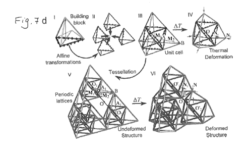
[0075] Fig. 7d shows steps used to create an assembly of the low-CTE
tetrahedra of Fig.
7c forming a unit cell in accordance with one embodiment; the unit cell being
shown before
and after deformation under a temperature variation;
[0076] Fig. 8a shows a monomaterial low-CTE tetrahedron shown in deformed and
undeformed states;
[0077] Figs. 8b to 8e show bi-material low-CTE tetrahedra shown in deformed
and
undeformed states;
[0078] Fig. 8f shows a bi-material tetrahedron with intermediate CTE shown in
deformed
and undeformed states;
[0079] Figs. 8g to 8j show bi-material high-CTE tetrahedra shown in deformed
and
undeformed states;
[0080] Fig. 8k shows a tridimensional view of a monomaterial high-CTE
tetrahedron
shown in deformed and undeformed states;
- 12 -
CA 03097190 2020-10-15
WO 2018/227302
PCT/CA2018/050723
[0081] Figs. 9a to 9c show tridimensional views of bi-material tetrahedra in
deformed and
undeformed state;
[0082] Figs. 9d to 9f are graph illustrating the variation of the CTE in the z-
direction in
function of the skew angle and in function of the ratio of the CTE of the
material of the
tetrahedra of Figs. 9a to 9c, respectively;
[0083] Figs. 9g to 9h are CTE magnitude plotted in polar coordinate system of
the
tetrahedra of Figs. 16a to 16c, respectively; Figs. 10a-10b show a
tridimensional view of a
screw geometry illustrating a 3-fold axes of symmetry with its top view shown
in Fig. 10b;
[0084] Figs. 10c shows a top view of building blocks assembled with 3-fold
axes;
[0085] Fig. 10d shows an axonometric view of the unit cell of Fig. 10c;
[0086] Figs. 11a to 11c show tridimensional views of different variations of
unit cells with
unidirectional CTE tunability;
[0087] Figs. 11d to 11e show tridimensional views of the unit cells of Figs.
11a to 11c;
[0088] Figs. 11g to 11i show tridimensional views of the deformed and
undeformed of the
unit cells of Figs. 11a to 11c;
[0089] Figs. 11j to 111 show top view of assemblies of the unit cells of Figs.
11a to 11c;
[0090] Figs. llm to 110 show axonometric views of the unit cell assemblies of
Figs. 11j to
111;
[0091] Fig. 11p to 11r show CTE magnitude plotted in polar coordinate system
with
respect to the principal directions; the semi-axes of each CTE ellipsoid are
the CTE
coefficients of the unit cell of Figs. 11j to 111;
[0092] Figs. 12a to 12c show tridimensional views of different variations of
unit cells with
transverse isotropic CTE tunability;
-13-
CA 03097190 2020-10-15
WO 2018/227302
PCT/CA2018/050723
[0093] Figs. 12d to 12e show tridimensional views of the unit cells of Figs.
12a to 12c;
[0094] Figs. 12g to 12i show tridimensional views of the deformed and
undeformed of the
unit cells of Figs. 12a to 12c;
[0095] Figs. 12j to 121 show top view of assemblies of the unit cells of Figs.
12a to 12c;
[0096] Figs. 12m to 120 show axonometric views of the unit cell assemblies of
Figs. 12j to
121;
[0097] Fig. 12p to 12r show CTE magnitude plotted in polar coordinate system
with
respect to the principal directions; the semi-axes of each CTE ellipsoid are
the CTE
coefficients of the unit cell of Figs. 12j to 121;
[0098] Figs. 13a to 13c show different variations of unit cells with isotropic
CTE tunability;
[0099] Figs. 13d to 13e show tridimensional views of the unit cells of Figs.
13a to 13c;
[00100] Figs. 13g to 13i show tridimensional views of the deformed and
undeformed of the
unit cells of Figs. 13a to 13c;
[00101] Figs. 13j to 131 show top view of assemblies of the unit cells of
Figs. 13a to 13c;
[00102] Figs. 13m to 130 show axonometric views of the unit cell assemblies of
Figs. 13j to
131;
[00103] Figs. 13p to 13r show CTE magnitude plotted in polar coordinate system
with
respect to the principal directions; the semi-axes of each CTE ellipsoid are
the CTE
coefficients of the unit cell of Figs. 13j to 131;
[00104] Figs. 14a and 14b show tridimensional views of building blocks made of
A16061
and TI-6A1-4V;
[00105] Figs. 14b and 14d show tridimensional assembly drawings of the
building blocks of
Figs. 14a and 14b;
- 14 -
CA 03097190 2020-10-15
WO 2018/227302
PCT/CA2018/050723
[00106] Fig. 14e show a tridimensional view of a building block made with
rigid joints and
being made of acrylic and PTFE for the bars and ABS for the joints;
[00107] Fig. 14f is tridimensional view of an assembly drawing of the building
block of Fig.
14e;
[00108] Fig. 14g is shows tridimensional views of the joint of Fig. 14e;
[00109] Fig. 14h shows a tridimensional view of a testing sample of a building
block with
black and white pattern for DIC testing;
[00110] Fig. 15a is a graph illustrating predicted curve and experimental
results of effective
CTE for Al/Ti and Al/Invar building blocks (TL-2 and TN) within a range of
skewness, along
with the CTE of the solid materials;
[00111] Fig. 15b is a graph illustrating predicted and experimental CTE
results along the
principal directions for the concepts with unidirectional CTE and principal
directions within
the plane x1 -x2 for other concepts here examined;
[00112] Fig. 16 are graphs illustrating normalized specific stiffness in the
vertical direction
for TL-1, TL-2, and TN building blocks as a function of the skew angle for
selected values of
the stiffness ratio of the components (Es2/Es1): Young's modulus (Fig. 16a)
and shear
modulus (Fig. 16b); p* representing the relative density;
[00113] Fig. 17 is a graph illustrating the relation between the CTE and the
skew angle of
the unit cells of Figs. 8b to 8j;
[00114] Figs. 17a to 17i are contour plots representing the effective
stiffness in the CTE
tunable direction of the unit cells of Figs. 8b to 8j and of a benchmark;
[00115] Fig. 18a is a graph showing comparison of proposed and existing bi-
material
concepts for given bar thickness ratio of 0.04 on the basis of (i) CTE
tunability shown as bars
on the left for Young's modulus in the CTE tunable direction, and (ii)
specific stiffness for
prescribed shown as bars on the right;
-15-
CA 03097190 2020-10-15
WO 2018/227302
PCT/CA2018/050723
[00116] Fig. 18b is a graph showing CTE tunability of the building blocks of
Figs. 8b to 8j
plotted versus structural efficiency compared to a benchmark;
[00117] Figs. 19a shows a tridimensional view of a tetrahedron with low-CTE
having four
low-CTE bars and two high-CTE bars;
[00118] Figs. 19b to 19d show tridimensional views of unit cells constructed
from the low-
CTE tetrahedron shown in Fig. 19a
[00119] Fig. 19e show a tridimensional view of a tetrahedron with intermediate
CTE;
[00120] Figs. 19g to 19h show tridimensional views of unit cells constructred
from the
building block of Fig. 19e;
[00121] Figs. 20a to 20d show tridimensional views of low-CTE unit cells with
transverse
isotropic CTE tunability;
[00122] Figs. 20e to 20h show axonometric views of the unit cells of Figs. 20a
to 20d;
[00123] Figs. 20i to 201 show to views of the unit cells of Figs. 20a to 20d;
[00124] Fig. 21a is a graph showing the effective CTE in function of the skew
angle for the
TL-2 concept;
[00125] Fig. 21b is a graph showing the effective CTE in function of the skew
angle for the
TN concept;
[00126] Fig. 22 are tridimensional views showing the structural hierarchy of a
3D lattice
having a low thermal expansion coefficient;
[00127] Fig. 23 is a graph illustrating the coefficient of thermal expansion
as a function of
the hierarchical order of the lattice of Fig. 5;
[00128] Figs. 24a to 24h illustrate the method to build a bi-material Octet
cell;
- 16 -
CA 03097190 2020-10-15
WO 2018/227302
PCT/CA2018/050723
[00129] Figs. 25a to 25c illustrate fractal-like hierarchical lattice with n=0
(a); n=1 (b); and
n=2 (c) and a thermal deformation field in the x-direction (col. III) and y-
direction (col. IV),
cols. I and ll show the initial configurations for designed and fabricated
samples,
respectively;
[00130] Figs. 26a to 26c illustrate hybrid-type hierarchical lattice with skew
angle of 55
degrees (a), 60 degrees (b), and 65 degrees (c) and thermal deformation field
in the x-
direction (col. III) and y-direction (col. IV), cols. I and ll illustrate
initial configurations for
designed and fabricated samples, respectively; and
[00131] Figs. 27a to 27c illustrates hybrid-type hierarchical lattice with
wall layers of M=1
(a), M=2 (b), and M=3 (c) and thermal deformation field in the x-direction
(col. III) and y-
direction (col. IV), cols. I and II illustrate initial configurations for
designed and fabricated
samples, respectively.
DETAILED DESCRIPTION
[00132] Architected materials can be designed to elicit extreme mechanical
properties,
often beyond those of existing solids. They may be very appealing for use in
several fields of
engineering including aerospace, automotive and biomedical. In these
applications, the
target to maximize might be either structural, through attaining for example
minimum mass
at maximum stiffness, or functional, such as thermal dimension control, heat
transfer, band
gaps, mechanical biocompatibility, and others. For lightweight structural
applications, high
stiffness is desired for preserving the structural integrity and resisting a
variety of loading
conditions. In contrast, high compliance is required to adapt under other
loading conditions
for more functional applications, such as energy absorption. For functional
applications, an
architected metamaterial having a coefficient of thermal expansion (CTE) that
is specifically
designed to provide at least one of a large positive, zero or negative CTE via
material
.. architecture tuning.
[00133] The design freedom to adjust thermal expansion is particularly
advantageous in a
large assortment of applications. On one hand, in extreme thermal
environments, sensitive
applications that require very fine precision, such as satellite antennas,
space telescopes,
-17-
CA 03097190 2020-10-15
WO 2018/227302
PCT/CA2018/050723
and large array mirrors, call for materials with zero CTE so as to avoid
undesired thermal
deformation. On the other hand, there are other applications requiring
materials with large
positive or negative CTEs. These materials must induce responsive and
desirable
deformations under given changes in temperature, often, but not always,
dictated by the
surrounding environment, such as in morphing and adaptive structures, as well
as MEMS.
The potential of periodic architected materials is also appealing because
their repeating cell
can be designed to concurrently maximize multiple performance requirements,
notably
structural and functional. Among many, examples of multifunctional lattices
include those
developed for aerospace components that can maintain precise dimensional
tolerances
under large temperature fluctuations and specific stiffness requirements.
[00134] In the present disclosure, the focus is on multifunctional lattices
designed with the
objective of providing unique control of thermal expansion and structural
performance. The
present disclosure deals with material architectures made of two materials,
which can be
designed to compensate the mismatched thermal deformation generated by each of
the two
materials. If exploited, this strategy enables the attainment of an overall
thermal deformation
that can be large positive, zero or large negative. Since dual material
architectures achieve a
tunable CTE through a purely mechanical, and thus temperature-independent,
mechanism,
their CTE is extremely dependent on the unit cell architecture and on the
difference in CTE
of their constituent solids. To assess the potential of a given architected
material in providing
a range of CTE values via tailored selection of its material constitutes and
its cell topology,
we need a quantitative metric. CTE tunability, (ACTE), has been recently used
to measure
the maximum range of CTE values that a concept can achieve upon changes of its
unit cell
geometry from a given pair of materials. Whereas a single material has only
one CTE value,
hence no ACTE , the CTE of dual material concepts can be adjusted by geometric
manipulation of the building block with the result of obtaining a range of CTE
values. The
difference between the minimum and maximum CTE that an architected material
can offer is
defined as ACTE . For a given concept, a large ACTE indicates ample freedom to
tune the
unit cell geometry, an asset that can release the dependence on the CTE ratio
of the
constituents.
-18-
CA 03097190 2020-10-15
WO 2018/227302
PCT/CA2018/050723
[00135] Preserving high specific stiffness in a dual-material construction has
to date been
thought to be in conflict with the need of enhancing ACTE . The stretch-
dominated unit cells
constructed by dual-material triangle (2D) or tetrahedron (3D), as described
herein, are
however believed to enable reducing the penalty that an increase in ACTE
typically
generates on the elastic properties of the material.
[00136] Structural hierarchy is one factor governing high stiffness, strength,
and toughness
in both natural and bio-inspired materials, and even more recently in the
field of thermal
expansion. However, how to exploit structural hierarchy to, first, amplify CTE
tunability in
architected materials, and then to decouple physical properties that are in
conflict, will be
described herein.
[00137] The design freedom to adjust thermal expansion is particularly
advantageous in a
large assortment of applications that require responsive and desirable
deformations,
including zero thermal expansion, under given changes in temperature.
[00138] All existing concepts have a trade-off caused by the inherent thermo-
elastic
coupling that they feature, a condition that makes desired changes in thermal
expansion
penalize elastic stiffness, and vice versa.
[00139] Referring now to Fig. la, the mechanical mechanism of thermal
expansion of the
basic building blocks that can attain a low-CTE performance (LD) is
illustrated. The elements
are shown as unconnected in Fig. la-II for clarification purposes. In the
illustrated
embodiment, the building block is a diamond 10 that comprises elements 12
composed of a
high CTE material and elements 14 composed of a low CTE material. At Fig. la-
I, the
diamond is shown at its original position. In Fig. la-II, the elements 12 and
14 of the
diamond 10 are not bounded with one another. Upon a uniform increase of
temperature,
elements 12 (aõ) and 14 (oc2) in the diamond 10 deform at different rates. The
height
increase, AHn , is caused solely by thermal expansion in elements 14.
[00140] Now referring to Fig. the elements 12 and 14 of the diamond 10
are
bounded with one another. Hence, in this configuration, rigid connections at
the nodes (or
vertices) 16 cause a higher expansion in the horizontal bar, or elements 12,
that turns the
-19-
CA 03097190 2020-10-15
WO 2018/227302
PCT/CA2018/050723
elements 14. As a result, the top vertex 18 of the diamond 10 springs back by
Aff12 a
displacement that if desired can be conveniently designed to compensate AfIn .
By
harnessing the values of the CTE as1 and a2, or the skewness of the elements
14, 9, the
CTE of a LD 10 might be tuned to zero, or even negative, in the y-direction.
[00141] Now referring to Fig. 1 b, a building block in the form of a diamond
20 having a
shape similar to the diamond 10 of Fig. la is illustrated at rest. However,
the material
distribution of elements 12 and 14 is switched to yield a high-CTE diamond
(HD) 20. The
expansion of the elements 12 bring about a height increase, AHhi , and a width-
wise gap,
AWh , which would appear if the element 14, which exhibits less expansion,
were visualized
as unconnected at nodes 16. Rigid connections at the nodes 16 would compensate
the
visualized horizontal gap, AWh , by a height increase of AHh2, adding on to
AHhi , and this
value of A11h2 can also be tuned by manipulating the CTE a1, as2 and the
skewness O.
This bi-material building block therefore has a diamond shaped topology,
wherein a first
material element 14 extends transversely through the diamond shaped topology
to
interconnect two "minor" vertices 16 (i.e. the two vertices of the diamond
that are closest
together to define the narrow width of the diamond) thereof.
[00142] Hence, in the depicted embodiment, the CTE in the y-direction depends
on the
thermal expansion ratio of the constituent materials,
= dirs2/asl, and the skewness angle,
O. If 9 is given, the smaller the
the lower (for LD) or higher (for HD) the CTE; hence the
greater the CTE distinction of the constituent solids, the higher the CTE
tunability.
[00143] Now referring to Fig. lc, in 3D, the building blocks shown as
tetrahedron 30 before
(I) and after the thermal expansion (II) are shown. Triangular (2D) or
tetrahedron (3D)
tessellation with these building blocks is applied to develop low thermal
expansion lattices
with low mass and high specific stiffness at levels currently unmet by
existing concepts.
[00144] Below is examined the general case of a LD 10 (Fig. la-l) with an
arbitrary skew
angle, 9, and its Young's moduli is derived, from which those for HD 20 can
also be
- 20 -
CA 03097190 2020-10-15
WO 2018/227302
PCT/CA2018/050723
obtained. A small thickness ratio is considered, ti/ <1/8, that gives LD a low
relative
density, p*Ips, which is defined as the ratio of its real density over the
density of the solid.
For a generic dual-material unit cell, the relative density can be expressed
as a function of
the volume fractions of the constituents, and more specifically for a LD can
be written as:
p* cos0+2 t
Ps sin / (Al)
[00145] Using structural mechanics, the in-plane Young's moduli can be derived
as:
\
E; ( 1
__________________________ Es2lEs1' t (A2) E51lE52 t
E52 0 tan' 0 1
E52 tan /
(A3)
[00146] where E51 and E52 are the Young's modulus for solid materials 1 and 2,
respectively. We note that although Eqs. (A2) and (A3) are valid for a defect-
free lattice in a
fully undeformed state, the thermal deformation and fabrication imperfections,
which are
less than 1% of the bar length deviation, will not significantly reduce the
elastic moduli (no
more than 5%). Even under the largest achievable temperature changes
considered herein (
AT = 50 C), the thermal deformation remains small, thereby causing no
significant impact
on the elastic moduli.
[00147] Since the thermal expansion mismatch between the constituent materials
cause
bar bending, the effective CTE in the y-direction can be written as:
(
cos 1
a51 ¨a2
ay as2
2 8 cos 8 (t/02 sin2 0/(8 cos' 8 (t102) + cos 012 + (E511 E52) 1
(A4)
[00148] Similarly in the x-direction, the effective CTE is:
- 21 -
CA 03097190 2020-10-15
WO 2018/227302
PCT/CA2018/050723
a1¨a2
a x a si
(sin2 (Esi /Es2 ))/(8 cos'8 (t/02 + cos (Esi /Es2 )/2 + 1
(A5)
[00149] Eq. (A4) can be simplified as:
ay = as2 + kCTE (asl ¨s2)
(A6)
(
-1
where Ifc,TE, = cos 8/2 ¨ (8 cos 8 (tll)2) (sin2 8/8 cos' 8 (t11)2
+cos812+(EsilEs2)-1 ) has
always a negative value. The LD 10 and HD 20 cases can be specified by the
difference in
values of the two solid CTEs. If as1>
s2'1.6
ay* is less than the lowest CTE of the two solids
(i.e. a2), thus representing LD Fig. la-l). On the other hand,
if dws2 > asl then a; is larger
than the highest CTE - in this instance as2 - which corresponds to the HD case
(Fig. lb-1).
[00150] In Eqs. (A4) and (A5) above, the effective CTE is also governed by the
geometric
parameters of the lattice, namely and O. The stiffness can also be
expressed similarly to
the CTE, since they are contingent on the same set of geometric parameters
(i.e. tfi and
in the Eqs. (A2) and (A3)). From this, it appears that a change of this set of
parameters
would make both the CTE and stiffness vary. How to avoid this thermo-elastic
coupling is
illustrated below, after how to enlarge ACTE in architectures made of any pair
of materials
is explained.
[00151] Now referring to Fig. 2, to verify the triangulation strategy as well
as the model
predictions, one planar bi-material lattice, fabricated as a proof-of-concept
from laser cutting,
is examined herein. The low-CTE diamond 10 (Fig. la) is separated into two
triangles and,
by incorporating mechanical elements, the proof-of-concept's CTE can reach
about 1.3x 10-
6/ C with a Young's modulus of about 1.8 GPa in y-direction. In the
illustrated embodiment,
the high CTE material is Al 6061 and the low CTE material is Ti-6A1-4V. Other
suitable
material may be used. Horizontal elements are made of the high CTE material.
The
assembly of unit cells (5 by 5) is illustrated in Fig. 2V.
- 22 -
CA 03097190 2020-10-15
WO 2018/227302
PCT/CA2018/050723
[00152] Now referring to Fig. 3, the LD 10 and HD 20 (Fig. 1) unit cells
introduced above
can be used as building blocks to create multiscale self-repeating lattices
(fractal-like
hierarchical lattice) with potentially unbounded range of CTE without severe
penalty in
specific stiffness. This can provide better trade-off between thermal and
mechanical
performance. This performance is achieved with neither change of their
constituent materials
nor manipulation of their skew angles. The underlying principle here is that
by replacing the
solid constituents with unit cells with higher (HD) and lower (LD) CTE values
than those of
their base materials, ACTE may be amplified.
[00153] The stretch-dominated bi-material diamond-shaped unit cells with low-
(LD) and
high-CTE (HD) 10 and 20 (Fig. 1) introduced above are proposed as building
blocks to
create multiscale self-repeating fractal-like hierarchical lattice 60 (Figure
3a) with a
potentially unbounded range of CTE. The strategy here described can be used to
create
fractal-like HL with anisotropic positive or negative thermal expansion,
either lower or higher
than the CTEs of the constituent materials, as well as high structural
efficiency originating
from the stretch-dominated cells they are built from. Thus the strategy might
provide better
trade-off between thermal and mechanical performance than existing concepts.
Fig. 3b
illustrates an example of hybrid-type hierarchical lattice 70 with two levels
of hierarchy. A
change in unit cell shape, i.e. a triangle, is implemented at n=2 to show how
hierarchy can
be effective in not only decoupling but also tuning thermo-elastic properties.
[00154] Still referring to Fig. 3, the low-CTE example of fractal-like
hierarchical lattice 60
with two hierarchical orders, each constructed through the tessellation of LD
10 and HD 20
with prescribed internal angle 0 = 60 , is shown. The reverse performance
case, i.e. higher
CTE, can be obtained by a switch of HD and LD positions. Higher orders can be
introduced
to reduce or enlarge the effective CTE in desired directions with high
structural efficiency (
El p) originating from the stretch-dominated cell this fractal-like
hierarchical lattice is built
from.
[00155] For the analysis, we consider the general case of nth order fractal-
like HL of
density p: , effective Young's modulus E:, and effective CTE ce:. The cell
walls consist of
LD and HD cells of density, p*, , effective Young's modulus, E_1, and
effective CTE,
- 23 -
CA 03097190 2020-10-15
WO 2018/227302
PCT/CA2018/050723
*
an 1 = The skew angle 0 is given and common to all hierarchical orders,
whereas the
thickness ratios ti//, are different. The relative density for the general
case of fractal-like HL
with n orders is:
* ( P 6?-h2n( tn" t2"t1 (COS0 2n n ( t . n cos
___________________________________________ 11 (A7)
ps sin 0 , 1 n / 12 / 11 / sin 0 , i_1
[00156] The Young's modulus of the high- and low-CTE fractal-like HL in the y-
direction
can be expressed as:
,
* *
( / 4, -\ ¨1
___________________ + _________
E1,y,i 1 El,y,i-1 I E h,y,i-1 ¨t i .. (1 < i < n, tan' 8 .. 1.
El*,y,i-1 .. \, 2 sin' 8
J =
E* = E (A8)
E* ( E* I vl h0 sh,
h,y,i 1,y,i-1 1 E*
h ,y,i-1 1 ti
E* = E
* ,-1
+ ______________________________________ 1,y,0 si j
E1
,_1 2 sin ' n 8 tan 8 1
1
[00157] where h and i represent the high- and low-CTE, respectively, and i
represents
the hierarchical order, such that El*y,i is the effective Young's modulus of
the low-CTE
element in the i th order and the y-direction. Their effective CTEs are given
by:
1
( * * cos 0 1 ah,y,i-1 ¨a1,,_1
11 = a /,y,i-1
a* * co2s 0 1 a1,y,i-1 ¨ ai-1
h,y,i = a1 __________________________________ 1,
a
8cos 0 (ti illi 1)2) sin2 0(ti illi 1)2 18cos3 0+ cos 012+ E* .1 1E* .
1 0,9)
2 8cos 0 (ti di 1)2 i sin2 0 (ti di 1)2 /8cos3 0+ cos 012+
a* a* * El *,y,0 Esl .
[00158] with 1 < i < n, = a = a sh , 10 sl E
, 0 = E sh , and =
[00159] The relations above show that fractal-like HL 60 of any hierarchical
order
possesses anisotropic thermo-elastic properties that are coupled. Isotropic
(planar)
behaviour can be attained by changing cell shapes among structural order, i.e.
by creating
- 24 -
CA 03097190 2020-10-15
WO 2018/227302
PCT/CA2018/050723
hierarchical lattices, with shapes that exhibit isotropy. This strategy is
applied below and self-
repeating lattices that are shaped at the last order with cell geometry
dissimilar than those of
the preceding orders, so as to create hybrid-type HL 70, are considered.
[00160] Fig. 3b illustrates an example of hybrid-type HL 70 with two levels of
hierarchy. A
change in unit cell shape, i.e. a triangle, is implemented at n = 2 to show
how hierarchy can
be effective in not only decoupling but also tuning thermo-elastic properties.
As opposed to
the fractal-like HL 60 in Fig. 3a, which contains both LD and HD, in Fig. 3b
only LD 10 (Fig.
1) is used at n =1 to create a triangle hierarchical lattice with low-CTE,
whereas its high-
CTE counterpart can be obtained by swapping the material position. We shape a
hybrid-type
HL 70 at n = 2 with a triangle to infer isotropic (planar) mechanical
properties and control
thermal expansion with LD at n = 1. This strategy might be effective in
achieving desired
levels of property decoupling which can be readily extended to lattices of
higher hierarchical
order and beyond CTE and stiffness, such as CTE and strength, CTE and
Poisson's ratio,
thermal-conductivity and Poisson's ratio, and others.
[00161] Let's examine hybrid-type HL 70 with n = 2 as illustrated in Fig. 3b.
If the 2nd
order consists of LD 10 (Fig. 1) only, then its overall effective CTE, a2 , is
equal to the CTE
of LD in the axial direction (y-direction in the current case), which can be
simply expressed
a2 = aly
as This shows that a2 is not dependent on any changes in geometry
at the 2nd
9
order, such that 2 and t22 have no influence on the effective CTE of the
overall hybrid-
type HL 70. However, any geometric changes at the first order, such as the
skew angle, will
a*
affect not only lY but also the CTE of the overall hybrid-type HL 70, i.e. a2
. With respect to
YE*
elastic stiffness for hybrid-type HL 70, the normalized effective Young's
modulus E 2 1 of
the 2nd order, which is mainly a function of unit cell topology, nodal
connectivity, cell wall
angle, and relative density, */*
P2P 1 , can be expressed through the wall thickness ratio,
as:
- 25 -
CA 03097190 2020-10-15
WO 2018/227302
PCT/CA2018/050723
(t,
E2*
____________ k2 ¨
E1 12
(A10)
[00162] Where k2 is a function of the cell topology adopted at the 2nd order
of hybrid-type
HL; q depends on the cell wall deformation mode of the 2nd order - stretching
or bending -
and can assume values that depend on the scaling condition applied to the cell
wall cross-
section. If E.: is given, the stiffness of the 2nd order is merely a function
of the geometry at
the 2nd order and any geometric change at this order will not influence the
overall CTE of
hybrid-type HL.
[00163] The thermal and mechanical 2D isotropic behaviour of the hybrid-type
HL 70 in
Fig. 3b derives from the shape of the unit cell, in this case a triangle. The
relevant properties
of hybrid-type HL 70 at n=1 are given in Eqs. (Al), (A2), and (A4), and the
mechanical
= 60
properties at n=-' ( 2 ) in Eqs. (A11) and (Al2). Since the CTE of the
last order
hybrid-type HL 70, a2 , is equivalent to that of the preceding order, in this
example the CTE
of LD, or HD for the high-CTE case, the thermomechanical properties of hybrid-
type HL are
given by:
P2 2.,sh t2 E* 2,5 t2
2
* *
A 12 (A11) Ei*y 3 /2
(Al2) a2 = aly
(A13)
[00164] To demonstrate CTE tuning that brings no change in the elastic
properties of
01 t
/4
hybrid-type HL, we seek in its first order a set of pairs for the skew angle
and that
can satisfy the condition of constant E1*Y . This can be achieved by
rearranging Eq. (A4) to
E*
find the expression of 1Y that is governed by t /4 and 1, and whose solution
provides
CTE values at the first order, al , that change with the skew angle but leave
E1*Y
substantially unaltered. This strategy substantially preserves the Young's
moduli in the
second order and allows CTE tuning in the first order. Furthermore, this
scheme enables to
- 26 -
CA 03097190 2020-10-15
WO 2018/227302
PCT/CA2018/050723
construct hybrid-type HL 70 with tunable stiffness via changing wall thickness
at the second
order, t
22 while keeping the overall CTE a2 constant, hence allowing thermo-elastic
decoupling.
[00165] The explanation given above is of course demonstrative for hybrid-type
HL of 2
orders. If n > 2 and hybrid-type HL has the triangle at the last (n th) order,
the scheme still
holds and enables to decouple CTE from elastic stiffness. In this case, the
first order to the
(n-1)th order are made of low-CTE fractal-like HL; and the relative density
and thermo-
elastic properties of the highest order can be expressed using Eqs. (A11) to
(A13) by
replacing 2nd order terms with n th order terms and 1st order with ('')th
order. The
Pn 1 n*
effective properties - , E_1 and an-1 in those general equations can be
calculated
through Eqs. (A7), (A8) and (A9), respectively.
[00166] Now referring to Fig. 22, a tridimensional hierarchy lattice with
tunable CTE is
illustrated. In a particular embodiment, the two order hierarchical lattice
can provide design
freedom to decouple thermo-elastical properties.
[00167] Now referring to Fig. 23, the graph shows that the range of CTE values
of a
tridimensional lattice increases with its hierarchical order (n).
[00168] Now referring to Fig. 24a-24h, in the illustrated embodiment, the bi-
material Octect
cell (Fig. 22-11) is built using the pretension snap-fit technique. Other
techniques, such as,
but not limited to, 3D printing, can be conveniently used to build these
materials at multiple
length scale from the nano to the meter scale. First, laser cutting is used to
cut a shape in a
sheet metal or other suitable material. Second, a given skew angle is imposed
using sheet
metal hot extrusion processes. Third, the diagonal elements are snap-fitted.
As illustrated in
Fig. 24d, a wedge is used for pretension. Then, the horizontal elements are
snap-fitted and
the joints are reinforced using epoxy glue or other suitable material. Figs.
24g and h show
the octet cell assembly using unbended and slightly bended elements,
respectively.
- 27 -
CA 03097190 2020-10-15
WO 2018/227302
PCT/CA2018/050723
[00169] Figs. 25a to 27c illustrate three sets of experimental validation for
the prediction
models presented earlier. The validations are performed on laser cut
prototypes of
hierarchical lattices. Given the scheme presented here is material selection
free, a
representative pair of materials is chosen to fabricate the samples. In a
particular
embodiment, the materials are Teflon Polytetrafluoroethylene (PTFE, DuPont,
USA), and
acrylic plastic (Polymethyl Methacrylate (PMMA), Reynolds Polymer, Indonesia).
Other
suitable materials may be used. The properties of these materials are
disclosed in Table 1
below. Nevertheless, the experimental validation here provided can be applied
to lattices
made of any pair of solids including metals, such as A16061 and Ti-6A1-4V, and
for
hierarchical orders above 2.
Table 1: Predicted and experimentally 111CaSUred CIE values x WPC) for solid
materials.
M )deasured Measured CTE GTE provided
Difference 'Young's Density
aterial
CTE (DK) (TMA Q400) by the supplier (%)
Modulus (G Pa) (g/cm3)
Acrylic
(Low CTE 67_0 10.5 69_0 2 9% 3 2 1.2
component)
Teflon PTFE
(high GTE 123_0 _1-0.9 120_0 25% 0_475 2.2
component)
A1606I 22_6 10.4 23 0 I 7%
[00170] The first set of experiments is illustrated in Figs. 25a-25 and aims
at validating the
fractal-like HL 60 (Fig. 3) model that can predict CTE values and its
tunability (Eq(A9)),
where the low-CTE of a representative lattice is tested in the y-direction.
The second set is
illustrated in Figs. 26a-26c and is designed to measure CTE tunability for
hybrid-type HL 70
(Fig. 3) with n = 2 (Eqs. (A4) and (A13)), and the third set illustrated in
Fig. 27a-27c is used
to demonstrate thermo-elastic properties decoupling (Eqs. (A4) and (A13)).
[00171] In a particular embodiment, sheets of 1.59 mm thickness of each
material are used
and laser cut to build 2nd order fractal-like 60 and hybrid-type HL 70 (Fig.
3). In a particular
embodiment, the laser cutter was calibrated to provide planar deviations
within 0.05 mm.
Bar elements 12 and 14 (Fig. 1) were individually embedded to diamond-shaped
cells and
epoxy glue was applied to provide adherence between materials. Other suitable
glue may be
used. In a particular embodiment, the epoxy glue thickness was about 0.1 mm,
2% of the
typical length of a lattice element; the epoxy CTE (65x10-6/00) was similar to
the CTE of
- 28 -
CA 03097190 2020-10-15
WO 2018/227302
PCT/CA2018/050723
acrylic, thus providing negligible influence on the CTE measurements of HL
samples. A 3D
digital image correlation (DIC) set-up with a temperature controlled heating
chamber was
assembled and used to assess the CTE of each set of HLs. In total, 3 sets of
DIC
experiments were undertaken for a total of 9 tests, 3 for each set.
[00172] Referring to Figs. 25a-25c, in the first group, DIC was applied to
solid bars of
acrylic (Fig. 8a) and 2 fractal-like HLs, one with 1 order of hierarchy (Fig.
25b) and the other
with two orders of hierarchy (n = 2, Fig. 25c). The skew angle ( 0 = 60 ) as
well as the wall
thickness ratio, which is about tit = 0.1 in the illustrated embodiment, of
the fractal-like HL
were kept identical. The joints were shaped in hexagons to preserve strut
connectivity (six)
at each node. To perform DIC, black and white speckles were applied randomly
and
uniformly across the nodes for thermal displacement measurements. The obtained
CTE
values along with theoretical and simulated values are summarized along their
corresponding columns. Computational values are obtained via asymptotic
homogenization.
[00173] Now referring to Figs. 926a-26c, the second set features DIC results
for 2nd order
hybrid-type HL samples with varying skew angles (55 , 60 and 65 ) and
hexagonal nodes
of dimensions identical to those of the first set (Fig. 25a-25c). To prove CTE
tunability of
hybrid-type HL for constant Young's modulus, Ey*1, the geometry of the three
hybrid-type HL
(Figs. 9a to 9c) samples was kept identical with the exception of their skew
angles, 01, and
wall thickness, to in the first order. The computational values are obtained
via asymptotic
homogenization.
[00174] Now referring to Fig. 27a-27c, in the last set of samples, second
order hybrid-type
HL were built with varying strut thickness to assess the impact of t2/12 on
their effective
CTE. Here the geometric parameters of all samples were kept identical except
the thickness
ratio of the second order (n = 2) chosen as the only variable. The number of
LD along the
thickness direction varied from M =1 to M =3 as shown in Fig. 27a, 27b, and
27c. The
computational values are obtained via asymptotic homogenization.
- 29 -
CA 03097190 2020-10-15
WO 2018/227302
PCT/CA2018/050723
[00175] For the test of Figs. 25a to 27c, testing temperature was monitored
and managed
from 25 C to 75 C through a PID (proportion-integration-differentiation)
controller. DIC
system calibration ensured an epipolar projection error below 0.01 pixels,
i.e. the average
error between the position where a target point was found in the image and the
theoretical
position where the mathematical calibration model located the point. A CCD
(charge coupled
device) camera was used to focus on an area of 240x 200 mm2 with a resolution
of
2448>< 2048 pixels; based on the image resolution, any deformation smaller
than 0.98 pm
(0.01 pixels) was merged by the epipolar projection error. Finally the
accuracy of the whole
testing system was verified with measures taken from a commercial
thermomechanical
analyzer.
[00176] In the illustrated embodiments, the testing system was calibrated on
three solid
materials, A16061, acrylic and PTFE. Table 1 above shows a comparison of their
measured
and predicted mean CTE along with their standard deviations, with errors below
3%. The
epipolar projection error is at 0.98 pm, which governs the smallest measured
CTE value of
the samples, i.e. 0.27x10⁻⁶/ C. The low magnitude of these errors warrants the
required
accuracy for the DIC system used in this work.
[00177] Figs. 25a-III and IV show thermal deformation maps for the solid
material, acrylic,
in both x- and y-directions, respectively. The tested CTE is observed
isotropically in all
directions in the 2D plane. While their thermal deformation is shown in Fig.
25a to Fig. 27a-III
and IV in both x- and y-directions, mean CTE from testing are summarized in
Table 2 below,
along with their standard deviation and CTE predictions. The error associated
with testing
results only go as high as 5%, and the difference between tests and the
computational
values obtained via asymptotic homogenization (AH) are generally within 10%
error, with the
exception of fractal-like HL (n = 2) sample, where the amplified low-CTE
behaviour also
amplifies the deviation between both results.
- 30 -
CA 03097190 2020-10-15
WO 2018/227302
PCT/CA2018/050723
Table 2: Predicted and experimentally measured CTE values for fractal-like and
hybrid-type HL (Y., and (7,. indicate
standard deviation).
Predicted CTE (Beam Measured CTE
Sample Error
Theory, 10 '1"C) (x 0 6..xe)
t'T k' X .4'
Fractal-like !IL (n=1) 115.0 62.0 1 15.210.3 60.3 12.4 0.2%
2.8%
Fractal-like !IL (n=2) 138.7 20.8 125_511.3 29_2 10.9 10.5%
110-rid-type I IL (55. M=2) 43.4 49.6 11.3 12.5%
hybrid-type I IL (60'. M=2) 49.4 52.1 0.6 5.2%
hybrid-type I IL (65'. M=2) 55.0 56A 12.9 2.5%
hybrid-type I IL (60". M=1) 50.3 511 11.3 5.3%
hybrid-type I IL (60'. M=2) 50.3 52.711.6 4.2%
110-rid-type I IL (60'. M=3) 50.3 52.711.6 4.2%
[00178] Fig. 25b-IV illustrates that LD (Fig. 25b-I, n=1 with 0 = 60 ) without
structural
hierarchy can reduce the CTE along the y-direction from 67.0x10⁻⁶/ C (n = 0,
i.e. the
component material, acrylic, as shown in Fig. 25a-1) to 60.3x10⁻⁶/ C. However,
for increasing
hierarchical order, fractal-like HL (Fig. 25c-1, n = 2) can further reduce the
effective CTE in
the y-direction to 29.2x10⁻⁶/ C, result obtained with no change in material
selection nor skew
angle. By adding hierarchical orders from n=1 to n=2, fractal-like HL shows a
CTE tunability
up to 31.1x10⁻⁶/00.
[00179] Fig. 26-III and IV show for hybrid-type HL the decrease of the
effective CTE from
56.4x10⁻⁶/00 (01 = 65 ) to 49.6x10⁻⁶/00 (8 = 55 ), which emphasizes a much
smaller CTE
tunability (6.8x10⁶/00) in comparison with adding hierarchical orders (31.1x10-
6/00). The
combination of varying skew angles and adding hierarchical orders appears to
be proficient
in tuning the effective CTE. For the last set of specimens, however, the
effective stiffness
relative to an hybrid-type HL with M =1 is expected to double for M = 2 and
triple for
M =3 ; the overall effective CTE displays a tendency of remaining
substantially constant
around 53x 10-6/ C. These results experimentally show that thermo-elastic
properties can be
decoupled in hybrid-type HL, as explained in more detail below.
[00180] Referring now back to Figs. 4a-4d, which illustrate the CTE values for
low- and
high-CTE fractal-like HL 60 (Fig. 3) in the y-direction as a function of
hierarchical order. Each
of the plotted lines, obtained from Eq. (A9), represents CTE values for a
given skew angle,
0, and starts from n = 0, solid materials, through n = 1, the HD and LD,
followed by fractal-
- 31 -
CA 03097190 2020-10-15
WO 2018/227302
PCT/CA2018/050723
like HLs with increasing hierarchical order
2. We recall that these predictions represent
discrete values of CTE, each obtained for a given n, although the trends are
shown as
continuous to ease their interpretation within each figure. Assuming the CTE
of PTFE and
acrylic as the high and low CTE values, respectively, we observe that as the
order increases
from 0 to 1, the effective CTE of HD is higher than that of PTFE, whereas the
CTE of the LD
is lower than that of acrylic. The gap between these two CTE spectra, i.e. LD
and HD, taking
0 = 60 as an example, enlarges from 56x10-6/ C (initial gap between solid
materials) to
93x10-6/ C, meaning an increase of 165% in ACTE . As the order changes from 1
to 2, the
gap increases even more drastically to 154.7x10⁻⁶/00 (275% of the initial gap)
and larger
once more from order 2 to 3, reaching 257.3x10⁶/00 (460% of the initial gap).
CTE tunability
(ACTE) increases with the order of hierarchy, so as to theoretically approach
an unbounded
value for unlimited n.
[00181] We also note the shaded region in Fig. 4a, where the lattice collapses
to a by-layer
laminate. This concept can cover CTE values between the CTEs of the
constituent solids by
changing their layer thickness ratio. Furthermore, Fig. 4b illustrates
structural efficiency - a
metric expressed here as the ratio of the specific stiffness of the lattice to
that of the solid
materials - in the y-direction of low- and high-CTE fractal-like HL versus
hierarchical order.
For normalization purposes, solid acrylic (blue in figure) is considered as
benchmark with
100% structural efficiency. With the increase of hierarchical order, the
structural efficiency of
fractal-like HL decreases. This is expected as stretch dominated lattices
become more
compliant with higher order of hierarchy. Figs. 4a and 4b show that the thermo-
elastic
properties of fractal-like HL are coupled, and CTE changes as structural
efficiency does.
[00182] Figs. 4c, 4d show the predicted CTE and structural efficiency for
hybrid-type HL 70
(Fig. 3) as a function of the hierarchical order and the skew angle, 611, in
the range
50 ¨ 70 , which is representatively chosen here to visualize the effect of
varying skewness.
In Fig. 11c, the first order (n =1 ) allows some degree of CTE tailoring with
a gap increase
between the low and high CTE spectra from 56x10-6/00 to 93x10-6/00. With the
addition of
the second order (n=2), this time hybrid-type HL, as opposed to fractal-like
HL, allows
stiffness modulation without thermal expansion variation. Hence CTE
substantially remains
- 32 -
CA 03097190 2020-10-15
WO 2018/227302
PCT/CA2018/050723
insensitive, i.e. ACTE between the first two orders is constant, despite a
drop of structural
efficiency.
[00183] The trends shown in Figs. 4c and 4d between n = 1 and n = 2 are now
used as
example to show how hybrid-type HL can be effective in decoupling thermal and
mechanical
properties. To do so, we first show that CTE and Young's modulus for LD are
inherently
coupled and hence no independent tuning is possible. This is shown in Figs.
5a, 5b where
Eqs. (Al) to (A5) are plotted in dash style along with results obtained from
AH (continuous
style), here included to provide a further element of validation to the
analytic models
presented therein.
[00184] Fig. 5a shows that for prescribed t1/11 , a reduction of the skew
angle brings a
decrease of both the CTE and Young's modulus in the y-direction. On the other
hand, if the
skew angle is given and t1/11 varies (Fig. 5b), both the CTE and Young's
modulus in the y-
direction show a monotonic increase for rising relative density. Hence Fig.
5a, 5b visualise
the thermo-elastic coupling that exists in diamond lattices.
[00185] Fig. Sc, d show results for CTE and Young's modulus obtained from Eqs.
(Al2)
and (A13) for hybrid-type HL of two orders (Fig. 3b-I). Also in this case,
results from closed-
form expressions are reported along with those obtained computationally via
AH. Fig. Sc
shows that a changed 611 in the first order of hybrid-type HL enables CTE
tuning for both
orders, while causing no impact in the Young's modulus, as shown by its
unchanging trend.
Likewise in the mechanical spectrum, Fig. 5d shows that the effective Young's
modulus can
be varied with relative density with no effect on the CTE. It is the thickness
ratio of the
second order, t2/12 , that, in this case, is the variable empowering the
Young's modulus
modulation for inviolate values of CTE. Figs. 5a-5d, thus, give a visual
summary of model
predictions validated through experiments for thermo-elastic coupling, which
appears to
have been bypassed with hybrid-type HL. This is achieved in (c) through
changing both the
skew angle of the first order, el , and t1/11, and in (d) by keeping these
parameters constant
and varying the relative density of the second order, P7P: =
- 33 -
CA 03097190 2020-10-15
WO 2018/227302
PCT/CA2018/050723
[00186] Experimental results with specifics illustrated in Figs. 25a to 27c,
are reported in
Fig. 5a, 5c and 5d and provide validation to the trends obtained via closed-
form expressions
presented above. Thermo-elastic properties of fractal-like HL in Figs. 4a-4d
demonstrate that
the addition of only one order of hierarchy enlarges the CTE tunability by
66%, which is up to
five times higher than what can be obtained through a change in skew angle. On
the other
hand, hybrid-type HL allows an increase in structural efficiency equal to
0.0585 of 20.6%
(Fig. 11 at n = 2) with respect to that of fractal-like HL (0.0485) at the
identical order.
Validated models of hybrid-type HL suggest that concepts with higher orders
can offer much
larger CTE tunability than stretch-dominated lattice benchmarks and superior
mechanical
performance than baseline concepts that are bend-dominated, in addition to
their decoupled,
planar isotropic therm 0-elastic properties.
[00187] To compare the thermo-elastic performance of fractal-like and hybrid-
type HL (
n 5) with the existing ones, in particular L-Concept and S-Concept, we plot in
Fig. 6a bars
of their specific stiffness, a measure of structural efficiency, and of ACTE,
the CTE tunability
defined as the maximum range of CTE values a concept can offer. The magnitude
of a given
performance metric is represented by the bar height. All concepts are compared
on an equal
basis, as they are generated from the same pair of materials (PTFE and
acrylic). With
respect to the left-hand side bars of CTE tunability in Fig. 6a, ACTE is
calculated for each
concept and for a given value of Young's modulus, which is representatively
considered here
as 1 MPa. From the bar rises, we gather that fractal-like HL dominates with
the largest CTE
range (534x10-6/ C), whereas ACTE for the S-Concept is the smallest (169x10-6/
C).
ACTE for hybrid-type HL (331.1x10⁻⁶/ C) is as high as that of L-Concept
(332.6x10⁻⁶/ C),
which is claimed to provide unbounded ACTE. This is quite unique, as the L-
Concept relies
on bend-dominated cells, whereas the proposed hybrid-type HL can obtain a
similar result
using a much stiffer structure. Similarly with respect to structural
efficiency (right-hand side
bars), Fig. 6a provides a visual comparison of the specific stiffness of each
concept for a
representative CTE value that is here assumed as half the average of the
materials' CTE
(47.5x10⁻⁶/ C). From the bars, we observe that fractal-like HL has the highest
specific
stiffness in the y-direction (349.2 KPaxm3/Kg) followed by hybrid-type HL
(116.5
KPaxm3/Kg), both of which outperform the existing concepts. More specifically,
focusing on
planar isotropic materials, hybrid-type HL provides a 42% increase in
structural efficiency
- 34 -
CA 03097190 2020-10-15
WO 2018/227302
PCT/CA2018/050723
compared to the stiff, yet dense, S-Concept (82 KPaxm3/Kg), while
demonstrating twice the
specific stiffness of the L-Concept (51.7 KPaxm3/Kg).
[00188] A more comprehensive comparison of the concepts is illustrated in Fig.
6b, where
CTE tunability is plotted versus specific stiffness. The curves are created
from a parametric
study of the unit cells, where the skewness angle and the thickness-to-length
ratio are the
active variables for given materials. Hybrid-type and fractal-like HL are
compared with L-
Concept and S-Concept, the benchmarks. While both high- and low-CTE cases
(Fig. 11) can
be plotted, Fig. 6b displays only the low-CTE concepts which are sufficient to
capture the
potential of hierarchical lattices. We recall that, in this low-CTE case, ACTE
is defined by
the range between the lowest CTE value of a given low-CTE concept, at the
calculated
structural efficiency, and the CTE of the solid material with lower thermal
expansion (i.e.
67x10-6/ C of acrylic). As can be seen, in these examples, a ratio of the
first (high) CTE to
the second (low) CTE may be between 0.1 and 10, and wherein a range of CTE
(ACTE),
defined between a lowest CTE value of the lattice structure and a CTE of a
solid material
having lower thermal expansion, is between 100 x 10-61 C and 550 x 10-6/ C.
[00189] While S- and L-Concepts show curves that describe the change of ACTE
with
structural efficiency, hybrid-type and fractal-like HL are represented by two
domains. These
shaded regions represent the possible set of curves that are obtained with
varying
hierarchical orders. For both cases, the first hierarchical order that makes
up the concept (
n =1 for fractal-like HL and n =2 for hybrid-type HL) provides the most
optimal curve
(closest to the top-right corner). The following hierarchical orders (the
second for fractal-like
HL, and the third for hybrid-type HL) provide the least optimal curve, while
higher orders lie
in between. Higher hierarchical orders are predicted to approach the curve of
the first order (
n = 1 for fractal-like HL and n = 2 for hybrid-type HL) with increasing n.
[00190] In general, Fig. 6b shows a Pareto-front for the existing concepts,
thus showing
trade-offs between metrics: an attempt of increasing structural efficiency
results in a reduced
ACTE. This trade-off is not only influenced by the relation between geometric
parameters
and effective properties, but also by the design requirements. For example,
the L-Concept is
the ideal candidate to attain large CTE tunability, whereas the S-Concept is
ideal for
- 35 -
CA 03097190 2020-10-15
WO 2018/227302
PCT/CA2018/050723
structural efficiency, as both are designed for different specifications. When
considering the
concepts presented in this paper, a better overall performance can be observed
compared to
the existing baselines. The curves derived from both fractal-like and hybrid-
type HL are
offsets of the L- and S-Concept toward the top right corner on the figure,
where both high
CTE tunability and high structural efficiency are achieved; hence their
domains show higher
potential of hierarchical lattices to attain better trade-offs between ACTE
and E/p
[00191] In Figs. 6a-6b, results are obtained from a parametric study of unit
cell geometry,
where the list of possible sets of properties for each concept are sorted by
increasing
structural efficiency, and then grouped based on a range of similar values of
the Young's
moduli over density ratio. The minimum CTE value is selected from each group
to calculate
ACTE for a given ratio El p . This value, the median structural efficiency of
each group, is
plotted as a point on the graph with the corresponding ACTE value on the
ordinate axis.
[00192] Referring now to Fig. 7a that shows a two-dimensional triangle made of
three
pivotably (i.e. hingedly) connected rods. As shown, a material length vector M
and a thermal
displacement vector N are shown. The direction of the material length vector M
defines a
referential direction along which the thermal expansion is measured, and whose
magnitude
describes the distance between two points on the triangle. If point one of the
two points is
selected as a stationary reference, with a change in temperature (AT), the
other of the two
points can move away from its original location to reach a generic point B'
(Fig. 7c),
thereby creating the vector, N, which is defined as the thermal displacement
vector. The
vector N extends from the original position of the other of the two points to
its final position.
[00193] Assuming there is no rigid-body translation or rotation of the CTE in
the direction
of M, am , can be expressed as:
M = N
[00194] a = M2AT (B4)
[00195] where " = " represents the dot product and AT is a scalar representing
the
temperature variation. Hence, for a unit change in temperature the CTE in any
arbitrary
- 36 -
CA 03097190 2020-10-15
WO 2018/227302
PCT/CA2018/050723
direction is the thermal extension or contraction, per unit length of a line
drawn originally in
that direction. The simple concepts for ML and TD vectors described above for
a solid
material (Fig. 7a), can be extended to a dual-material triangle truss in 2D
(Fig. 7b) and
further to a tetrahedron truss in 3D (Fig. 7c). With a temperature increase,
the height rise of
.. the dual-material triangle in Fig. 7b, triggered by the blue elements with
low CTE is
compensated by the sinking of its top vertex (Point B) due to the higher
thermal expansion of
the red bar with high CTE. In Fig. 7b-I, the ML vector describes the direction
of thermal
expansion between the midpoint of the base ( OAc , taken here as the reference
point) and
the apex (point B), which is the only CTE tunable direction in the triangle.
By harnessing the
CTE values of the solid components, as1 and a2, or the skewness of the blue
elements, 0,
we can tailor the CTE of the dual-material triangle in the vertical direction,
so as to assume
one of the following value: positive (Fig. 7b-II) with codirectional ML and TD
vectors;
negative (Fig. 7b-III) with ML and TD vectors in the opposite direction; or
zero with a zero TD
vector.
[00196] Similarly in 3D, the M vector of the dual-material tetrahedron (Fig.
7c-I, ) is
defined by the apex (point B) and the centroid of the base triangle (point 0,
taken as the
reference point). With a temperature increase, the height rise, i.e. the
thermal expansion in
the M direction, triggered by the blue elements is counteracted by the sinking
of its apex
due to the higher thermal expansion of the red base (AACD). In this case, all
lateral faces
(i.e. BAC, BAD, and BCD) of the dual-material tetrahedron are low-CTE
triangles (Fig.
7b-I), and the resultant of all three ML vectors of the low-CTE triangles
(i.e. M1, M2, and M3
in Fig. 7c-I) passes through points 0 and B. Thus, the direction of the
resultant vector given
by the sum of M1, M2, and M3 (each representing the only CTE tunable direction
in 2D) is
equidirectional to the M vector of the tetrahedron (green vector in Fig. 7c-I,
representing the
only CTE tunable direction in 3D). This observation highlights a directional
relationship of
CTE between a tetrahedron and its triangular faces: the resultant of the 2D ML
vectors of the
triangles specifies the CTE tunable direction of the tetrahedron, chosen here
as the direction
of the 3D ML vector. In other words, the direction of the tunable thermal
expansion in the
triangular faces governs that of the overall tetrahedron. This rule is also
useful for locating
the ML vector direction of other types of dual-material tetrahedra, along with
the CTE tunable
- 37 -
CA 03097190 2020-10-15
WO 2018/227302
PCT/CA2018/050723
directions, as explained in the following section. As per the magnitude, the
effective CTE in
3D, similar to the 2D case, can be tailored to be positive (Fig. 7c-I1),
negative (Fig. 7c-III),
and zero through a change in 9 and/or as1las2. In both 2D and 3D cases, the
apex point B
can be termed as stationary node , since for the zero-CTE case its position
relative to the
reference point can remain stationary during thermal expansion.
[00197] The ML and TD vectors can also express the CTE of an assembly of
building
blocks, such as the unit cell shown in Fig. 7d-III Here in this exemplifying
case, simple affine
transformations, in particular translation and rotation (Fig. 7d-I1), are used
to assemble the
dual-material building block (Fig. 7d-1) into a unit cell with multiple
subunits (Fig. 7d-I1). The
assembly of the four tetrahedra in Fig. 7d-II creates a high CTE octahedron
core within the
unit cell (Fig. 7d-I11). The ML vectors, M1 in orange for the octahedron core,
and M2 in
green for the tetrahedron (Fig. 7d-III), can be defined between the center of
the unit cell,
point 0, taken as the reference point, and the vertex B, separated by point A
(Fig. 7d-I11).
The overall thermal expansion behavior between 0 and B is given by the sum of
the
.. corresponding vectors, M1, M2, and the TD vectors, N1 and N2, of these two
thermally
distinct parts, OA and AB. Hence the thermal expansion of the assembled unit
cell in Fig. 7d-
III can be simply expressed as:
(Mk gµlk IMk)
a_k (k =1, 2) . AT1M k
[00198] k (B6)
[00199] We now show that the above ML and TD vectors can also be applied to
desired 3D
tessellations of compound units. Fig. 7d-V shows an example with a periodic
truss
assembled with the compound cell of Fig. 7d-III. The distance between the
centers of any
adjacent unit cells, such as between centers 01 and 2' can be accessed via ML
and TD
vectors, as shown in Fig. 7d-V and VI. In this case, the thermal expansion of
the spatial truss
can be simply expressed as:
- 38 -
CA 03097190 2020-10-15
WO 2018/227302
PCT/CA2018/050723
Nizy,
= k (k = 1 , 2) ,
1 2 ATIMR
[00200] k (B7)
[00201] where _Ariz, and m-Fy, are the components of Nk and Mk parallel to
0102,
respectively. We remark here that since the projection cosine of both Nrk and
MR, , i.e.
cos/3, is identical, the terms containing the directional angle, fl in Fig. 7d-
V and VI, cancel
.. out in both the numerator and denominator of Eq. (7). No matter which
direction is
considered, the CTE for this cell topology is identical in all directions,
thus equaling the
effective CTE evaluated by Eq. (6), i.e. 0µ002. = Gem. We can conclude that
since the thermal
expansions between centers of any adjacent unit cells are identical, the
overall CTE of the
truss material shown in Fig. 7d-V is thermally isotropic and the magnitude can
be evaluated
by the vector analysis explained above.
[00202] The concept presented in Fig. 7c and d are given as examples to show
the
handiness of using vectors to visualize and analyze thermal expansion of a
periodic truss
built from single units as well as a more complex assembly of compound units.
In both
cases, the primitive building block is a tetrahedron that features a distinct
arrangement of
solids in its bars. But this is just one among many other material layouts
that are feasible.
The following sections examine all the possible material arrangements that can
appear in the
strut of a dual-material tetrahedron, each defining a building block with its
own specific CTE
profile.
[00203] 2.2. Exploration of dual-material tetrahedra
[00204] The simplest 3D hinged structure that is free to deform upon
temperature changes
is a tetrahedron. Six types of rods can make up its frame, and different
combinations of
component materials or dimensions are possible. Below we examine all the
material
permutations that can occur in the struts of a dual-material tetrahedron, and
study the
relation that each of these has with the CTE along its principal axes. The
goal here is to
provide a foundational basis to understand other, more complicated, truss-like
materials.
- 39 -
CA 03097190 2020-10-15
WO 2018/227302
PCT/CA2018/050723
[00205] 2.2.1 Thermal deformation mode of dual-material tetrahedra
[00206] Let us consider a tetrahedron made of six rods, each made of a
material with either
low or high CTE, but both positive. Figs. 13a-13r show all the possible
material permutations
that can appear by simply switching the position of rods with high-CTE rods
shown in
dashed line, a1, and low-CTE rods shown in solid lines, a2. In total, there
are eleven
possible arrangements, each visualized by a tetrahedron from Fig. 8a to k. For
monomaterial
tetrahedra (e.g. Fig. 13a and 13k), the thermal expansion is uniform; as there
is no thermal
mismatch, no opportunity exists to tailor the CTE. For the remaining
tetrahedra, on the other
hand, CTE tunability is possible as the effective CTE can be adjusted in one
or more
directions. It is possible to split the nine tetrahedra into three groups:
= Low-CTE tetrahedra 100, 200, 300, 400 (Fig. 13b to 13e), which can yield
an effective
CTE that is lower than the CTEs of both the component materials; the high-CTE
bars
being shown in dashed line and referred to as 100a, 200a, 300a, 400a;
= lntermediate-CTE tetrahedron 500 (Fig. 13f), the only one able to attain
the effective
CTE of a value between the CTEs of the two components only; the high-CTE bars
being shown in dashed line and referred to as 500a;
= High-CTE tetrahedra 600, 700, 800, 900 (Fig. 13g to 13j), with effective
CTEs higher
than both the CTEs of the components; the high-CTE bars being shown in dashed
line
and referred to as 600a, 700a, 800a, 900a.
[00207] For a tetrahedron, the direction of the 3D ML vector with CTE
tunability is
controlled by the resultant of the 2D ML vectors of its triangular faces, and
can be purposely
chosen to align along one of the principal axes of a tetrahedron. As explained
in later
sections, this choice eases the assembly of building blocks in spatial
lattices and helps
identify the direction of CTE tunability.
[00208] Fig. 13b shows a tetrahedron in which one of the rods possesses high-
CTE as
opposed to the rest with low-CTE and hence defines two low-CTE triangles whose
resultant
sets the direction of the for this tetrahedron. The tetrahedron of Fig. 13b
has one line YY
- 40 -
CA 03097190 2020-10-15
WO 2018/227302
PCT/CA2018/050723
that is stationary with respect to the rod YY that is made of the high-CTE
material. The
tetrahedron of Fig. 13b is hence referred to as a tetrahedron with stationary
lines (TL-1) and
its effective CTE is expressed as:
[00209] For the zero-CTE case, points A and B are stationary nodes with
respect to the line
CD in the low-CTE triangles. Analogously, the relative position, including the
minimum
distance and skew angle between the two skewed lines, AB and CD, can be
constant under
a temperature change. We can thus name the pair of lines AB and CD as
stationary lines
(SL), and call the tetrahedron shown in 13b as a tetrahedron with stationary
lines (TL-1).
Under the pin-jointed assumption, through Eq. (4) we can obtain its effective
CTEs as:
ax asi
ay = as2
8TL-1 G (45 , 901.
as2 (as1 + as2 )cos2 8TL-1
a
[00210] 1¨ 2 cos2TL-1 (B8)
[00211] Where, in this case, the ML vector is aligned with the axis Z.
[00212] Fig. 13c and 13d show two other possible ways by which the positions
of high- and
low-CTE bars can be permuted. Here two high-CTE bars (shown in dashed lines)
and four
low-CTE bars (shown in solid lines) make up the tetrahedra: the high-CTE bars
of the former
meet at one of their vertices, while the high-CTE bars of the latter are not
in contact. In this
case, after thermal expansion, the tetrahedron is no longer a regular
triangular pyramid. In
Fig. 8d, all four triangles of the tetrahedron have a low CTE bar. The
tetrahedron in Fig. 8d
has a pair of stationary lines that can be used for CTE tailoring. The
effective CTEs of this
tetrahedron with stationary lines (TL-2) is defined as:
a x =a = a
y sl
as2 ¨ 2as1 cos2TL-2TL-2 E (45 , 90 ) .
z,TL-2
1 ¨ 2 cos2TL-2
[00213] la (B9)
[00214] For a tetrahedron with three high-CTE bars and three low-CTE bars,
there are
three possible ways by which bars can be arranged (Fig. 13e, 13f, and 13g). In
the
- 41 -
CA 03097190 2020-10-15
WO 2018/227302 PCT/CA2018/050723
arrangement shown in Fig. 13e, the high-CTE bars are connected in a loop. In
these cases,
the apex of the tetrahedra is a stationary node . The effective CTEs of the
tetrahedron of Fig.
13e is expressed as:
x y
{
= =
3as2 ¨4as1 cos20õ ,t9õ c (30 ,901. az, 77\I a a
= a
3 ¨ 4 cos 2 07,
[00215] (B10)
[00216] The effective CTE of the other tetrahedra may be similarly determined.
The CTE of
the regular tetrahedra presented above can be adjusted by manipulating both
material of its
constituents rods and geometric variables, in given directions. Herein, the
role of these two
CTE-dependent variables on the effective CTE of building blocks for both high-
and low-CTE
concepts are examined. Three CTE-tunable building blocks with different linear-
dominant
thermal deformation modes along the principal direction: TL-1 (Fig. 13b), TL-2
(Fig. 13d),
and TN (Fig. 13e). The zero-CTE cases of these building blocks are also
visualized in Fig.
13a, 13b, and 13c before and after thermal expansion; each tetrahedron is
orientated to
keep the ML vector along the vertical direction, demonstrating the concepts of
stationary line
and stationary node.
.. [00217] Referring now to Fig. 14d, 14e, and 14f, the effective CTEs of both
low- and high-
CTE tetrahedra along the z-direction against the skew angles are plotted. In
the case, the z-
direction, is the only CTE tunable principle direction while along the others
the CTE is that of
the constituent solids. As depicted in Fig. 14d, 14e, and 14f, the effective
CTE, az , of the
building blocks can be tuned by changing the skew angles to cover a large
range of values,
from large negative/positive to approximately zero, demonstrating a sizeable
CTE tunability.
Fig. 14d to f also demonstrate that the CTE in the z-direction depends on the
CTE ratio of
the constituent materials, A= as1las2. If the skew angle, 0, is given, the
larger/smaller the
/1,, the lower (for low CTE concept, Fig. 8b, d, and e) or higher (for high
CTE concept, Fig
13g, 13i, and 13j) the effective CTE, respectively. Hence the greater the CTE
distinction of
the constituent solids, the higher the CTE tunability. The aforementioned
building blocks
- 42 -
CA 03097190 2020-10-15
WO 2018/227302
PCT/CA2018/050723
distinguished by their own tunable characteristics lay the foundation for
designing stiff and
strong spatial lattices with tunable CTE, as shown below.
[00218] It is possible to construct lattices using the building blocks, TL-1,
TL-2, or TN,
along with their ML vectors aligned in the CTE tunable direction to program
thermal
.. expansion in spatial lattices with high specific stiffness and strength.
Notions of crystal
symmetry, in particular from the crystallographic point groups, are applied to
the building
blocks and used to assemble more complex truss systems that can meet desired
CTE
requirements. Nine examples of lattices are engineered to attain
unidirectional, transverse
isotropic, or isotropic controllable CTE. In a general case, the thermal
expansion
requirements a system should attain can be specified by: (i) the magnitude and
sign of its
CTE, which can be large positive, near zero, or negative, and/or (ii) the
thermal expansion
directionality, defining its anisotropic or isotropic behaviour. The former is
a requirement
mainly governed by the geometry and components of the building blocks. The
latter
correlates with the directions of the CTE properties that are governed by the
assembly rules
.. of tetrahedral building blocks, such as orientation, symmetry operations,
and relative
position, as explained below.
[00219] There is theoretically an infinite number of unit cells that can be
proposed to meet
the unidirectional requirement of CTE. Fig. 15a, 15b, and 15c show three of
them, each
constructed with its own building block and a specific relation of symmetry,
but all have
unidirectional CTE tunability in the vertical direction (x3).
[00220] The first unit cell in Fig. 11a consists of eight TL-1 building blocks
assembled via
reflection and rotational transformations to make each adjacent block appear
in an upside-
down position. In this unit cell, there are only three mutually perpendicular
2-fold axes with
an inversion center but no axes of higher order, e.g. 3-fold or 4-fold axes;
hence, the unit cell
has an orthorhombic symmetry (Fig. 11g). All ML vectors of TL-1s in Fig. 11a
are parallel
with the vertical direction and therefore the CTE-tunable mechanism of TL-1
governs the
thermal deformation of the unit cell in the vertical direction. The CTE tensor
of an
orthorhombic unit cell has three independent components with values equivalent
to the
principal CTEs. Although the overall CTE is orthotropic, the entire lattice
shows
- 43 -
CA 03097190 2020-10-15
WO 2018/227302
PCT/CA2018/050723
unidirectional CTE tunability with magnitude of a3 = az, a (Eq. (B8)) that is
tunable in the
vertical direction only. Along the other two principal directions al =as1 and
a2 a2, the
periodic lattice can uniformly expand with the CTE of its components. The
second unit cell
shown in Fig. 11b is structured with eight TL-2 building blocks via only
rotation around, and
translation along, the vertical direction. This unit cell has a 4-fold axis
with a middle mirror
plan, and thus classed as tetragonal symmetry. In its CTE tensor (Tab. 1),
there are only two
independent coefficients: al as1 and a3=az,H, 2 (Eq. (B9)). This unit cell,
although
obtained with symmetry relationship different from that of the previous model,
still keeps all
ML vectors of the building blocks along the vertical direction and therefore
results in a
unidirectional CTE controllable in the vertical direction. The unit cell in
Fig. 11c uses the TN
tetrahedron, which has a trigonal symmetry (Fig. 10b and Fig. 110. As
discussed above, the
only two independent coefficients are al a1 and a3 = az,TN (Eq. (B10)),
thereby
demonstrating unidirectional CTE tunability.
[00221] The three concepts in Figs. 11a-11r feature dissimilar symmetry
systems
constructed via different affine transformations, however, they all keep the M
vectors in the
CTE tunable direction along direction x3. The direction x3 of each concept
follows the
direction of the 2-fold, 3-fold, and 4-fold axes, which are principal
directions. Each unit cell,
therefore, inherits the CTE tunability of its building block in the principal
direction x3. Fig.
11p, q, and r illustrate their omnidirectional CTEs in a spherical coordinate
system, from
which a pertinent symmetry in thermal expansion appears for each case. The
direction with
the lowest CTE (dark blue in the legend), i.e. a single vertical axis for each
unidirectional
concept, is the principal direction of CTE tunability. No CTE tunability is
viable along the
other principal directions, i.e. plane x1 ¨x2.
[00222] 2.3.2 Transverse isotropic CTE Requirement
[00223] Fig. 12a, 12b, and 12c show three unit cells, each assembled with its
own building
block but all have trigonal symmetry to meet transverse isotropic CTE
requirement. In the
first example (Fig. 12a), low-CTE stationary lines of six TL-1s form the inner
core with two
- 44 -
CA 03097190 2020-10-15
WO 2018/227302 PCT/CA2018/050723
sets of triadic building blocks at the same altitude ( x3) arranged with equal
angular spacing.
On the middle mirror plane (Fig. 12g), three additional low-CTE bars are
added, combined
with the six low-CTE stationary lines, forming a central triangular bipyramid.
This operation,
considered along with the periodic tessellation in Fig. 12m, is enforced to
lock any
mechanism as well as to make the unit able to perform as a pin-jointed
structure. As shown
in Fig. 12g, the unit cell consists of 3-fold rotational symmetry, analogous
to the trigonal
crystal, it has only two independent components in the CTE tensor, al and a3.
All TL-1 ML
vectors deviate outward from the vertical direction by an identical deviation
angle, 7 (
E (0 , 90 ) with 7 = 75 in Fig. 12a), which, together with the skew angle and
component
CTEs, controls the horizontal effective CTE with in-plane isotropic CTE
tunability (a1 a2).
a2).
In the out-of-plane principal direction, i.e. x3, if the tessellation of unit
cells (shown in Fig. 12j
and m only along plane x1¨ x2 for visual simplicity) allows connection only at
the peaks of
the triangular bipyramid, there is no CTE tunability, resulting in a3 = as2.
Thus, the overall
effective CTEs of the unit cell in Fig. 12a are expressed as:
a2 cos 0 tan-17+ Las2 (a51 + as2)cos2
s
141 142
cos tan-1 +
[00224] a3 = s2 (B14)
= (1 ¨ 2 cos2
[00225] where
[00226] Similarly, for the second example in Fig. 12b, TL-1s are replaced by
TL-2 building
blocks to construct a unit cell with transverse isotropic controllable CTE. A
triangular
bipyramid core is constructed via six high-CTE stationary lines and three high-
CTE bars
added in the middle mirror plane. All TL-25 have an identical 7 (7 E (0 , 90 )
with 7 = 75 in
Fig. 12b). The symmetry relationship of the building blocks within the unit
cell in Fig. 12b is
identical to that of TL-1 concept (Fig. 7a), and the unit cell has thermal
expansion behavior
expressed as:
- 45 -
CA 03097190 2020-10-15
WO 2018/227302 PCT/CA2018/050723
a cos 0 tan-1 y (as2 2as1 cos2 0)/j
'Al 142
cos 0 tan-1 + =
= s
[00227] a3 al (B15)
[00228] The third example in Fig. 12c shows that TN building blocks can also
be
manipulated to construct a unit cell with transverse isotropic CTE. Six TNs
deviate from the
vertical direction by 7 (7 E (0 , 90 1 with 7 = 90 in Fig. 7c) and round up
their high-CTE
base members, together with the three high-CTE bars added on the middle mirror
plane, to
form the edges of a central polyhedron. Fig. 12i shows the unit cell in a 3-
fold rotational
symmetry, analogous to a trigonal crystal, resulting in only two independent
components in
the CTE tensor, al and a3 . Within the horizontal plane, the concept has in-
plane isotropic
CTE tunability (a1 a2). The out-of-plane tessellation (along plane x1¨x2 in
Fig. 70)
reveals a mere connection via the high-CTE cores, yielding a3 = as1 with no
CTE tunability
in the vertical direction. For this reason, the thermal expansion behavior of
the unit cell in
Fig. 12c is expressed by:
= (3as2 ¨ 4 cos2 Oasi )/4-+ ai cos 9
(11 = (12 ________________
ZNA cos2 0 +
= s
[00229] a3 al (B16)
= (3 ¨ 4 cos2 61/2
[00230] where
[00231] We remark that the top views shown in Fig. 12j, 12k, and 121 are the
3D analogues
of previous 2D concepts (Wei et al., 2016). The assembly of other spatial unit
cells can be
inspired by other 2D cell topologies in the literature (Miller et al., 2008;
Steeves et al., 2007).
Furthermore, as shown in the examples of Appendix A, the vertical direction
(x3) can also
possess CTE tunability by decreasing the deviation angle, 7. Fig. 12p, 12q,
and 12r show
the omnidirectional CTEs of the concepts in a spherical coordinate system. A
central
horizontal plane circularly shaped (dark blue in Fig. 12p to 12r) shows
principal directions
- 46 -
CA 03097190 2020-10-15
WO 2018/227302 PCT/CA2018/050723
with CTE tunability for each transverse isotropic concept. Contour plot
symmetry in Fig. 12p
to 12r also reflects the symmetry in thermal expansion, such as no CTE
tunability is viable in
the vertical direction.
[00232] 2.3.3. Isotropic CTE Requirement
[00233] Fig. 13a-13r show three unit cells, one for each row, possessing
isotropic
controllable CTE, with TL-1s, TL-25, and TNs as their building blocks
respectively. A regular
octahedron core is constructed by either stationary lines of TL building
blocks or high-CTE
base triangles of TNs. This monolithic core has a uniform thermal expansion in
all directions
and connects all building blocks via identical distance to the center of each
unit cell for given
angular space. All the unit cells have a cubic envelope as the unit cell
domain. Along the four
body diagonal directions of the cubic domain, four 3-fold axes can be found
for each unit cell
(Fig. 13g, h, and i), thus showing a cubic symmetry. Analogous to the cubic
crystal, there is
only one independent coefficient in the CTE tensor of each concept, and
therefore each unit
cell has identical thermal expansion in all directions. Hence, the tessellated
periodic lattices,
with all unit cells connected by either stationary nodes or stationary lines
(Fig. 13j to o),
feature a CTE that is isotropic with adjustable magnitude given by:
aõcos9 +Las2 ¨
\as1 + as2 )COS2 6)1/
[00234]
a Is TL 1 for Fig. 13-a; (B17)
cost9+
as1 cos 9 + (as2 ¨ 2a1 cos2 19)/
[00235]
also TL 2 ________________________________ for Fig. 13-b;
cost9+
(B18)
a51,5 cos +(a52¨ 413 a51cos2
___________________________________________________ [00236] also_TA, = for
Fig. 13-c. (B19)
\Ecos8+4"
[00237] The unit cells examined in Fig. 13a-13r are some among many other
possibilities.
Fig. 7d shows another example of a unit with isotropic CTE tunability,
previously studied in
the literature (Steeves et al., 2007); this cell has an analogous spatial
structure of carbon
atoms in a diamond, i.e. cubic symmetry. More examples are shown in Appendix
A. Fig. 13p
- 47 -
CA 03097190 2020-10-15
WO 2018/227302
PCT/CA2018/050723
to r indicate the omnidirectional CTEs of the concepts in a spherical
coordinate system.
Evidently, the isotropic CTEs are described by monocoloured spheres,
reflecting the
symmetry in thermal expansion. The principal directions can be randomly
selected within the
entire spherical space, yet obtaining the identical lowest CTE for each unit
cell.
2.3.4 Geometrical constraints of compound unit cells
[00238] For the nine concepts illustrated in Fig.s 11a to 13r, the effective
CTEs in the CTE
tunable direction can be programmed through a change of the skew angle, 8, of
the building
block. The range of 8 is restricted by certain values that preserve the
tetrahedral shape of
the building block, as well as avoid causing collision between adjacent unit
cells during
thermal expansion. For concepts with transverse isotropic CTE, the range of 8
is also
governed by 2/ . Tab. 2 shows the allowable range of 8 for each cell topology
with co
representing the packing factor of the lattice. A packing factor correlates to
a given
tessellation. For example, a packing factor of 100% is shared by the unit
cells shown in Fig.
6m, n, and o. In contrast, for the unit cells with isotropic CTE given ranges
of their skew
angles result in tessellations with lower packing factors, such as 50% for the
tessellation
shown in Fig. 130 (9=60 ). Differences in the packing factor are controlled by
the
requirement of the inner polyhedron, e.g. octahedron in Fig. 8c, to thermally
expand without
touching adjacent cells.
Unidirectional Transverse Isotropic
Isotropic
,
3)1
arccos (1+ csc2 y) 2 , = 50% (45 arccos
(-N5/
TL-1 (45 , 90 ) = 50%
and
TL-2 co =100% 1 (arccos (,5/3), 90 )
arccos (1 + csc2 y) 2 , 90 , cp =100%
q=100%
(
(300\ 2 ,, 2
, 90 ) ((3 ¨ COS 7) 4µµ (30 , 60
1,
TN 30 , arccos + ¨ , co = 50%
q=100% 3 sin2 3
- 48 -
CA 03097190 2020-10-15
WO 2018/227302
PCT/CA2018/050723
( 1
( , 2 4 (60 µµ,, 2
, 90 ) ,
arccos (3 ¨ cos 7) + ¨, 90 , q=100%
3 sin2 7 3
co =100%
[00239] 2.3.5. Summary points for prescribing thermal expansion in spatial
lattices
[00240] There are plentiful ways to construct 3D lattices from tetrahedral
building blocks.
Below, the key notions explained above are summarized to help assemble
tetrahedron-
based lattices that can meet given magnitude and directional requirements of
thermal
expansion. The distinguishing features are the building blocks with the
definition of their ML
and TD vectors, and the symmetry construction operations used to assemble them
in the
repeating unit.
[00241] Building blocks with their thermal expansion. The bi-material
tetrahedron is the
smallest building block chosen here for generating a periodic 3D lattice. Nine
relevant
.. material permutations are available (Fig. 8b to j), among which the most
practical are those
with stationary lines, TL-1 and TL-2, and with stationary node, TN. For each
of them, the
material length vector, ML, and the thermal displacement vector, TD, provide a
visual and
handy description of the magnitude and direction of their thermal expansion.
They assist in
meeting requirements of given CTE magnitude and closed form expressions are
given in
section 2.2 to quantify them.
[00242] Unit cell construction for prescribed CTE behaviour. Building blocks
can be used to
assemble complex compound units either with unidirectional CTE tunability
(e.g. Fig. 11a) or
with a number of tunable CTE directions (e.g. Fig. 13c), as prescribed by the
application
requirements. The crystal systems in Tab. 1 can assist their arrangement to
satisfy
directional requirements. If the symmetry relations of one crystal system
transfer to the
geometrical arrangement of building blocks in a unit cell, analogously the
independent tensor
components of that crystal system return into the CTE tensor of the overall
lattice. Here, the
tensor components of the unit cell represent the CTEs in the principal
directions, either with
or without CTE tunability, of the overall lattice. By following this strategy
the overall thermal
expansion of a spatial lattice built from compound units can be assessed
through the ML and
TD vectors of its constitutive building blocks (section 2.2).
- 49 -
CA 03097190 2020-10-15
WO 2018/227302
PCT/CA2018/050723
[00243] In this summary, we also remark that unit cell construction should
also meet
tessellation requirements, such as those ensuring minimum static and kinematic
determinacy, among others. If the assembly process leads to an unstable
mechanism,
additional members are necessary to lock in any mechanism, and additional
struts can be
inserted to match the CTE of its surrounding elements so as to avoid altering
the direction(s)
of CTE-tunability. In addition, because there are multiple tetrahedral
building blocks and
numerous relations of symmetry to choose from, the number of 3D tessellations
capable of
satisfying given CTE requirements can be countless. This work has presented
nine of them
(Fig. 6 to 8) obtained by implementing the scheme presented here, and the
following section
describes their proof-of-concept fabrication and thermal testing. Additional
concepts showing
the viability of the method are given in Appendix A.
[00244] 3. Fabrication and experimental validation
[00245] 3.1. Component materials
[00246] This section presents the fabrication and CTE testing of i) the
building blocks, TN
and TL-2, made from metallic constituents, and ii) the nine lattice concepts
shown in Fig. 11a
to 13r, made from polymers. The six constituent materials selected are:
A16061, Ti-6A1-4V,
and lnvar-36 as metallic constituents; and acrylic, Teflon PTFE, and ABS as
polymer
constituents. Tab. 3 shows their relevant properties.
Material
A16061 Ti-6A1-4V lnvar-36 Acrylic PTFE ABS
Young's modulus (GPa) 70.8 113.8 140.0 3.2
0.475 2.6
CTE (x 10-6/ C) 23.0 11.5 1.5 67.0
123.0 94.5
[00247] Accordingly, as can be seen above, a building block composed of
aluminum (as
the high CTE element) and titanium (as the low CTE element) will have a
relative difference
in CTE between the two constituent materials of about 11.5 x10⁻⁶/ C. A
building block
composed of PTFE (as the high CTE element) and acrylic (as the low CTE
element) will
have a relative difference in CTE between the two constituent materials of
about 56
- 50 -
CA 03097190 2020-10-15
WO 2018/227302
PCT/CA2018/050723
810-6/ C. A building block composed of aluminum (as the high CTE element) and
lnvar (as
the low CTE element) will have a relative difference in CTE between the two
constituent
materials of about 21.5 x10⁻⁶/ C. A difference a difference in CTE between the
first (high)
CTE of the first material and the second (low) CTE of the second material may
therefore said
.. to be between 10 x 10-6/0C and 60 x 10-6/0C.
[00248] 3.2. Engineering of specimens
[00249] 3.2.1 Fabrication of building block samples
[00250] Testing samples of building blocks were fabricated via pin-jointed
metallic bars
(Fig. 9a to d). Ti-6A1-4V shafts (low-CTE) were cut and sanded to the desired
length (Fig. 9b
.. and d) with each end shaped into a crevice. A flake in the shape of a ring
tongue terminal
was fastened in the crevice of bars by interference fit and strengthened via
administering
epoxy glue (LePage Epoxy Gel, Henkel, Canada) to serve as a hinge axle sleeve
for pinned
joints. As shown in Fig. 9, A16061 shafts (high-CTE) are thicker (diameter of
6.4 mm) than
the Ti-6A1-4V bars (diameter of 3.2 mm) so as to construct a stable base with
through-holes
drilled directly to serve as hinge axle sleeves. All the high CTE bars have
given length of
50mm (Fig. 9b and d), and the length of low-CTE bars vary for modifying the
skew angle at
given values. Then the assembly of the different tetrahedral samples were
completed using
bolts, screw nuts and washers. Since only rotation occurs and no bending
moment appears
at the joints, the tested CTE of pin-jointed building blocks are validated via
closed-form
equations in section 2.3 relying on the pin-jointed assumption. Furthermore,
in the fabricated
prototypes shown in Fig. 14a-14h, the length of the flakes (totalling about 12
mm at both
ends), compared with the typical length of the shaft (about 40 to 55 mm), is
not negligible.
Thus, the thermal effect of flakes on the overall effective CTE of lattices is
taken into account
to amend the analytical model as further explained in Appendix B.
[00251] 3.2.2 Fabrication of unit cell specimens
[00252] To ease the understanding of the spatial arrangement of building
blocks in all unit
cells, we built ball-and-stick models as proof-of-concepts (Fig. 11a to 13r).
Connection balls
(10 mm diameter) have several blind holes (with a 1.6 mm diameter and 2 mm
depth) in
- 51 -
CA 03097190 2020-10-15
WO 2018/227302
PCT/CA2018/050723
different orientations on the surface (Fig. 14g) to connect sticks (Fig. 14e
and 14f). All the
spheres are 3D printed (printer: Original Prusa i3 MK2) by ABS. The sticks
were laser cut
into different lengths, all from 1.6-mm-diameter rods made from either PTFE
(high-CTE) or
acrylic (low-CTE). Both ends of the sticks were plugged into the blind holes
of spheres and
then rigidly fixed by resin glue (LePage Epoxy Gel, Henkel, Canada). The
thickness of the
resin adhesive layer was very thin making the thermal expansion of resin glue
negligible. In
contrast, the ABS connection ball had a non-negligible thermal expansion, and
this deviation
is considered in a later section validating experimental measures against
theoretical and
simulation results.
[00253] Moreover, since the CTE properties of the concepts here introduced are
primarily
dependent on the unit cell geometry besides the CTEs of the constituent
solids, the
principles can be applied to systems across a wide range of length scales, and
hence
fabricated with both conventional and advanced methods. Additive manufacturing
is a viable
method that can be effortlessly used to assemble in large volume bi-material
lattices with
smaller element size, as demonstrated by recent works appeared in the
literature on this
topic.
[00254] 3.3. Experimental method
[00255] Both tetrahedral building blocks (Fig. 14a-14h) and compound unit
cells (Fig. 11a
to 13r) were experimentally investigated to validate their CTEs. For the
former, 12 physical
samples were tested to verify the respective theoretical models of TL-2 and TN
building
blocks (Eqs. (9) and (10) in section 2.2.1) with two dissimilar pair of
material combinations
and three different skew angles (see Appendix B for the images of the physical
samples of
the building blocks). The first material combination consisted of A16061 and
Ti-6A1-4V (i.e.
Al/Ti), and the second consisted of A16061 and lnvar (i.e. Al/Invar). In all
cases, Al was the
high CTE material while lnvar and Ti were the low CTE materials. The three
skew angles of
the building blocks for each material combination varied between 53 to 65
with
approximately equal angle difference. For example, if the 12 samples were
organized into
four sets of three, the first set would consist of three TL-2 samples made
from Al/Ti with
skew angles 53.5 , 61.7 and 63.7 , respectively. Besides building blocks,
nine physical
samples of the compound unit cells were tested, one for each of the concepts
shown in Fig.
- 52 -
CA 03097190 2020-10-15
WO 2018/227302
PCT/CA2018/050723
11a to 13r. The skew angles of all samples were set to 600, and the CTEs along
the principal
directions were measured by assessing the relative thermal displacement of the
connection
balls.
[00256] 3D DIC tests were performed to measure the thermal displacement of all
samples
with randomly distributed black and white pattern painted on the surface (Fig.
14h). DIC
testing consists of capturing images, before and after heating the sample
within a heating
chamber, at selected temperatures so that elongation can be measured. Testing
temperature was monitored and managed from 25 C to 75 C (for polymer samples)
or to
150 C (for metallic samples) through a PID (proportion-integration-
differentiation) controller
(0N7800, Omega, US). A data acquisition system (NI cDAQ 9174) was used to
measure the
temperature heterogeneity via collecting three thermocouples from different
locations in the
chamber. The temperature heterogeneity was regulated within 5% of the real-
time
temperature through the application of a rotational air fan. DIC system
calibration ensured an
epipolar projection error below 0.01 pixel, i.e. the average error between the
position where
a target point was found in the image and the theoretical position where the
mathematical
calibration model located the point. Two CCD (charge coupled device) cameras
(PointGrey,
Canada) were used to focus on an area of 240 X 200 mm2 with a resolution of
2448X 2048
pixel; based on the image resolution, any deformation smaller than 0.98 pm
(0.01 pixel) was
merged with the epipolar projection error. Using the DIC correlation software,
Vic-3D
(Correlate Solution Inc.), virtual extensometers were placed on the reference
image and
tracked through the images to measure the displacement between pairs of pixel
subsets.
The thermal deformation field (Fig. 10) was obtained from the relative
displacement between
these pairs of subsets. The effective CTE was calculated from thermal strain
and
temperature change. Finally, the accuracy of the whole testing system was
verified with CTE
measurements of a solid material, A16061, taken from a commercial
thermomechanical
analyzer, TMA Q400 (TA Instrument, US). A comparison of their measured
(22.6x10⁻⁶/00)
and DIC predicted mean CTE (23.0x10⁻⁶/00) shows an error of 1.7%. The epipolar
projection
error is at 0.98 pm, which governs the smallest measured CTE value of the
samples, i.e.
0.27x 10⁻⁶/ C. Hence, the low magnitude of these errors warrants the required
accuracy for
the DIC system used in this work.
- 53 -
CA 03097190 2020-10-15
WO 2018/227302
PCT/CA2018/050723
[00257] 3.4. Experimental results
[00258] The thermal testing results of both the building blocks and compound
unit cells are
here compared with results from either numerical analysis or closed-form
expressions (Fig.
15a-15b). The role of component materials and skew angle on the effective CTE
is
emphasized. In addition, the effect of connection type, either pin-joint
(building blocks) or
rigid-joint (unit cells), is assessed to validate the pin-jointed assumption
of the closed-form
expressions derived for ideal building blocks and compound unit cells.
[00259] A TN, both pin-jointed with similar 9 and identical components of
Al/Ti, are taken
as representatives to illustrate the tunable thermal displacement that each
tetrahedron can
provide along the principal directions. The horizontal thermal displacement
shown in Fig. 10
(a and b for TL-2 with 0 = 61.7 , e and f for TN with 0 = 63.3 ) indicates
that for both building
blocks, the effective CTE is high and positive (23x106/00), identical to that
of the high-CTE
constituent Al, i.e. no CTE tunability. In the vertical direction of TL-2, the
nearly alike light-
green color on nodes used for CTE measurement (i.e. nodes B1 and B2 in Fig.
10d)
indicates a near zero distance change. Thus, the effective CTE of TL-2
specimen in the
vertical direction is almost vanishing (3.70x10⁻⁶/ C). In contrast, along the
vertical direction
of TN, the distance between the two corresponding nodes, D1 and D2 in Fig. 10h
used for
CTE measurement, increases during thermal expansion, which results in a
positive effective
CTE (8.42x10⁻⁶/00), a value below those of its constituents Al (23x10-6/00)
and Ti
(11.5x10⁻⁶/ C). Thus for similar skew angle and identical constituents, TL-2
can attain a
lower CTE than TN.
[00260] In both directions, the thermal distribution of the former made of Al
and Ti, parallel
that of the latter, made of acrylic and PTFE, despite the difference in
magnitude caused by
each given pair of constituent materials.
.. [00261] Fig. 15aa illustrates the impact of the skew angle, building block
type, and
component material on the effective CTE of building blocks. For all sets of
samples, the CTE
reduces significantly with decreasing skew angle, whereas for high values the
CTE is less
sensitive; nevertheless, CTE tuning across the range of skew angle here
considered can be
achieved for both TN and TL-2. In addition, for prescribed pair of materials,
i.e. (Al/Ti) and
- 54 -
CA 03097190 2020-10-15
WO 2018/227302
PCT/CA2018/050723
(Al/Invar), the red and green curves show the CTE trend of TN with respect to
the skew
angle, and the blue and violet curves that of TL-2. The results show that the
CTE of TL-2 can
be tuned to a smaller value than that of TN, hence the ACTE of TL-2 is larger
in the given
range of skew angle. Another insight that can be gained from Fig. 15a pertains
to the role of
the CTE ratio of the constituents, i.e. A= a1/as2 . The greater the CTE
distinction of the
constituent solids (
11A1-Invar -% 15.3 which is higher than AAI_Ti = 2 . 0 ) , the larger the CTE
tunability of a building block. We also remark that the largest negative CTE a
building block
can reach in all experiments of this work is -26.2x10⁻⁶/0C (Al/Invar TL-2 with
0 =54.1 )
which is well below the CTE values of its components.
[00262] Fig. 15b compares the experimental (specimens with rigid-joints) and
theoretical
(closed-form expressions with pin-joints) results for the CTE of all the
compound units. The
relatively small errors associated with the testing results, which go as high
as 6.3%, validate
the CTEs under pin- and rigid-joint assumptions displaying small deviations,
hence
respecting the small deformation assumption. Another insight concerns the
effective CTE of
the building blocks here investigated. As shown in Fig. 15b, comparing the
three concepts
with unidirectional CTE tunability (i.e. specimens 1, 2, and 3 in Fig. 15b),
specimens with
stationary lines (TL-1 and TL-2) have smaller effective CTE values than that
of specimens
with stationary nodes. The conclusion up to this point is summarized as TL
concepts have
larger CTE tunability than TN concepts which also applies to the concepts with
identical
transverse isotropic or isotropic CTEs. The comparison between three concepts
made of TL-
1s (i.e. specimens 1, 4, and 7 in Fig. 15b), or other concepts made of the
identical building
block, show an increase in the effective CTE when the CTE-tunable
directionality increases
from unidirectional (one principal direction) to transvers isotropic (two
principal directions)
and then to isotropic CTE (three principal directions). An increase of CTE-
tunable
directionality is accompanied by the presence and size increase of the
monomaterial core of
concepts. For example, unidirectional cells contain no monomaterial core, but
transverse-
isotropic cells have small cores compared to isotropic cells' large cores. The
presence and
size of a monomaterial core make the effective CTEs increase with the size of
the core.
However, TL-2 concepts are more significantly affected by the high-CTE (red)
cores than TL-
1 concepts with low-CTE (blue) cores. Thus in Fig. 15b, with a triangular
bipyramid core,
- 55 -
CA 03097190 2020-10-15
WO 2018/227302
PCT/CA2018/050723
specimen 4 has a larger CTE than specimen 5, while in contrast, specimen 7 has
a smaller
CTE than specimen 8 when an octahedron core is constructed for the isotropic
concepts.
The fabrication and testing method reported in this work can also be applied
to building
blocks with effective CTEs higher than that of the constituents (i.e. high-CTE
cases as
shown in Fig. 8a-8k) as well as concepts with more complex architecture.
[00263] 4. Mechanical properties
[00264] To understand how a programmable CTE truss-system behaves as a bulk
material
with effective properties, we adopt here a classical continuum-based approach
that relates
the stress-strain behaviour of the unit cell to that of the global level. In
doing so, we assume
that the characteristic length of the unit cell is at least one or two orders
of magnitude below
the characteristic length of the truss-system. This scale separation between
the global
response and that of the unit cell allows us to calculate the effective
properties through a
continuum model (Arabnejad and Pasini, 2013). For three dual-material unit
cells with
unidirectional CTE tunability (TL-1, TL-2 and TN concepts shown in Fig. 11a-
11r), we
present in the main body of the text closed-form expressions of their elastic
properties, and
in Appendix E their buckling and yielding strength. For unit cells with
transverse isotropic or
isotropic CTEs (concepts shown in Figs. 12a-13r), a numeric approach is used
to obtain their
elastic properties.
[00265] Thermal expansion. The CTE of bi-material lattice materials depends on
the CTE
mismatch of materials, the skew angle, i.e. the interplay of the structural
members, as well
as the stiffness mismatch of materials and joints. Fig. 17 reveals the role of
the skew angle
in the thermal expansion performance of each low-CTE unit cell. As a general
trend, we
observe that as the skew angle increases from the minimum to the maximum value
of
range (Tab. 2), the CTEs for all units converge gradually to that of the low-
CTE solid material
(10 x10-6 1 C in Fig. 17). The similar upper bound indicates the largest ACTE
comes from
the concept obtaining the lowest CTE value. As shown in Fig. 17, with a given
range of skew
angles and given directional behaviour (i.e. unidirectional, transverse
isotropic, or isotropic),
the lowest effective CTE a TL-1 and TL-2 concept can achieve is generally
lower than that of
the TN concept. This demonstrates that concepts with stationary lines have a
better CTE
- 56 -
CA 03097190 2020-10-15
WO 2018/227302
PCT/CA2018/050723
tunability, because the CTE tunability of TL-1 and TL-2 building blocks is
higher than that of
the TNs (Fig. 9a-9i). Similarly, when comparing TL-1 with TL-2 concepts, the
latter has
generally a larger ACTE , especially for concepts with small or no
monomaterial core (i.e.
transverse-isotropic and unidirectional, respectively). However, for isotropic
concepts, above
0 = 53 TL-2 has higher CTE values than TL-1, as the influence of TL-2 high-
CTE
octahedron core is far larger than that of the low-CTE core of the TL-1
concept. For lattices
assembled with a given building block, TL-1, TL-2, or TN, the CTE tunability
is often the
smallest for unit cells with isotropic CTE, followed by unit cells with
transverse isotropic CTE.
This can also be attributed to the influence of larger single-material core
(octahedron) of
isotropic-concepts than the core (triangular bipyramid) of the transverse-
isotropic concepts;
the former is more effective in counteracting the CTE tunability via larger
monomaterial core
and hence impairing CTE tunability. On the other hand, the largest CTE
tunability in the
principal direction can be achieved by unit cells which have unidirectional
CTE with no
monomaterial core.
[00266] The experimental results in section 3.4 show that the CTEs under the
pin- and
rigid-jointed assumptions deviate marginally from each other. Under the pin-
jointed
assumption, the stiffness mismatch of the component materials has no effect on
the effective
CTE, as opposed to the case of the rigid-jointed assumption, where the
stiffness mismatch
of the components can play a role on CTE tunability. A relative comparison
between the
three factors here examined shows that the effect of the stiffness mismatch is
secondary to
the influence of the other two, namely the interplay of structures and the CTE
mismatch of
materials. Appendix A reports additional results on the CTE of rigid-jointed
bi-material
lattices obtained for a number of Young's modulus ratio of the constituent
solids.
[00267] Specific stiffness . The specific stiffness of all concepts increases
linearly with the
relative density p*. For increasing the skew angle 0 with constant p* , the
Young's modulus
is also observed to raise for unidirectional concepts while a parabolic effect
appears for the
remaining concepts (e.g. Fig. 17f and 17i), i.e. a rise is followed by
declining modulus. This
can be attributed to the changing alignment of the high-stiffness component
(i.e. low-CTE Ti
bars) along the loading direction: i) for unidirectional concepts, increasing
0 results in an
- 57 -
CA 03097190 2020-10-15
WO 2018/227302
PCT/CA2018/050723
incremental alignment along x3; ii) for both transverse-isotropic and
isotropic concepts, the
same incremental alignment is initially experienced along the loading
direction, before
beginning to deviate from the loading direction above a specific 0 value. The
parabolic
effect can also be observed for Fig. 15d, e, g, h, and j when a larger range
of 0 is plotted.
.. [00268] For given p* and 0, Fig. 17a - 17j highlights also similarities
between the
stiffness of TL-1 and TL-2 concepts. Compared to TL-2 concepts, TL-1 concepts
feature
slightly higher values of specific stiffness, due to presence of more Ti bars.
However, TN
concepts generally outperform the others in stiffness, especially for
transverse-isotropic (17f)
and isotropic concepts (Fig. 17i) where the parabolic effect is observed at 9
60 , resulting
in a much higher specific stiffness than TL concepts with identical 9, p*, and
CTE
directionality. Fig. 17j plots also the specific stiffness values for the
benchmark (Steeves et
al., 2007). Compared to this baseline, we notice that unidirectional and
transverse-isotropic
concepts produce higher stiffness along the direction of CTE tunability, but
the isotropic
concepts are comparable for given geometric and constituent parameters.
[00269] Trade-off between CTE tunability and specific stiffness.
[00270] The results above give an indication of existing trade-offs between
the properties
of the concepts here studied: ACTE and specific stiffness. To better
understand these
trade-offs, Fig. 18a shows bars of ACTE and specific stiffness simultaneously,
and in Fig.
18b ACTE is plotted versus specific stiffness to demonstrate Pareto-fronts,
both for all
concepts made of Al and Ti.
[00271] For Fig. 18a, the ACTE bars are calculated for all concepts under a
given stiffness
value (1 GPa), while bars of structural efficiency are all derived from
concepts with equal
CTE (6.5x 10⁻⁶/ C), a value lower than the CTE of their base materials:
Al/Ti). This allows for
a consistent comparison of their thermo-elastic performance. The bars are
arranged in order
of increasing number of CTE tunable principal directions, from unidirectional
to isotropic
concepts. Evidently, with increasing number of CTE tunable directions, there
is a penalty in
both ACTE and structural efficiency. The decrease in ACTE is due to the
presence and
increasing size of monomaterial cores, as previously observed. The drop in
structural
- 58 -
CA 03097190 2020-10-15
WO 2018/227302
PCT/CA2018/050723
efficiency, however, is attributed to the distribution of load bearing bars
along the CTE
tunable directions, thus resulting in a more uniform load capacity, but with
lower effective
stiffness along a specific direction. For unidirectional and transverse-
isotropic concepts, TL-2
unit cells provide the best ACTE and specific stiffness values, followed
closely by TN
concepts, while both performing significantly better than TL-1. However, for
isotropic
concepts, the TN thermo-elastic performance exceeds that of TL-2, due to the
reduced
performance of the TL-2 core.
[00272] The Pareto-front curves shown in Fig. 18b are generated from a
parametric study
of the unit cells, where the skewness angle and the thickness-to-length ratio
are the active
variables for given materials (Al/Ti). The curve shapes emphasize the trade-
offs between the
two metrics plotted: an attempt of increasing structural efficiency results in
a reduced ACTE
. This common trend demonstrates that the desired deformation that a large CTE
tunability
would require is generally antagonist to the high specific stiffness that is
distinctive of a
structurally efficient architecture. Here we notice that unidirectional
concepts excel in
structural efficiency along their CTE tunable direction; but for increasing
ACTE, their
specific stiffness drops. Transverse-isotropic unit cells are unable to attain
the highest level
of specific stiffness, but, within their attainable range, they generally
provide higher ACTE
compared to unidirectional concepts. Finally, for isotropic concepts,
including S-concept
(Steeves et al., 2007), there is a sacrifice in both ACTE and structural
efficiency, except for
the isotropic TN unit cell, which maintains performance similar to its
transverse-isotropic
counterpart. Overall, Fig. 18a and 18b provides a comprehensive comparison of
the thermo-
elastic performance of the concepts here examined, bearing in mind that no CTE
directionality is ultimately superior to the rest as the direction of CTE
tunability is entirely
dependent on the application requirements.
[00273] In certain embodiments described herein, three groups (low-CTE,
intermediate-
CTE, high-CTE) are introduced for the tetrahedral building block to tune the
effective CTE at
values that can be lower, in between, or higher than the constituent material
CTEs. For the
low-CTE group, three specific mechanisms are identified for a bi-material
tetrahedron: two
with stationary-lines, and the third with a stationary-node. Additionally, a
systematic method
to rationally assemble building blocks into compound units, such as the nine
here
- 59 -
CA 03097190 2020-10-15
WO 2018/227302
PCT/CA2018/050723
introduced, is described herein that can attain desired magnitude and
directionality of
thermal expansion in three-dimensional lattices. Further, means for resolving
the trade-off
between CTE tunability and specific stiffness, which has led to the assembly
of building
blocks into stiff and strong, yet high CTE tunable spatial lattices with
application across the
spectrum of length scale, are also provided.
[00274] Bi-material lattices built from tetrahedral building blocks such as to
permit
predetermined thermal expansion are thus described above. The material length
vector and
thermal displacement vector are first defined to assess thermal expansion of
truss concepts,
and then used to examine all the possible material permutations that can occur
in the struts
of a dual-material tetrahedron. The results establish underlying principles
governing
tailorable thermal expansion in dual-material lattice materials, where desired
CTE magnitude
and spatial CTE directionality can be programmed a priori to satisfy given CTE
requirements, such as unidirectional, transverse isotropic, or isotropic. This
works has also
shown that three-dimensional lattices can be systematically assembled with
high specific
stiffness to attain large CTE tunability over a substantial range of
temperature, thus
appealing to a large palette of applications where low mass, thermal stability
and thermal
actuation are primary goals.
[00275] Two dual-material tetrahedra with CTE tunability that can thus be used
to generate
six supplementary unit cells with given CTE behaviour. The first tetrahedron
(Fig. Ala) has
.. low-CTE tunability in the vertical direction with shear thermal deformation
during expansion.
The second tetrahedron, intermediate tetrahedron, is able to obtain the
effective CTE of a
value between the CTEs of the two components only. The additional concepts
shown in Fig.
Al can not only obtain transverse isotropic and isotropic CTE, as with
concepts shown in
Fig. 12a-12r and Fig. 13a-13r, but also orthotropic CTE. The unit cell has CTE
tunability in
both the x1 and x3 directions with different magnitudes. With the x2 direction
exhibiting no
CTE tunability, the concept overall demonstrates orthotropic CTE tunability.
[00276] The effective CTE of the dual-material tetrahedra shown in Fig. 19a
and 19e (M
direction) can be expressed respectively as:
- 60 -
CA 03097190 2020-10-15
WO 2018/227302
PCT/CA2018/050723
16as1cos2 0 ¨ , 0 c (15 , 751
az-L4H2
[00277] l6 cos 0-1 (Al)
4as1 cos2 0 + as2 0 c (36 , 72 )
az-L3H3
[00278] 4 cos20 +1 (A.2)
[00279] Fig. 20a-201 shows unit cells with transverse isotropic CTE governed
by the
deviation angle, 7 , and the skew angle, O. The decrease of 7 and increase of
9 allow the
connection of unit cells (Fig. 20a to 20d) in the out-of-plane principal
direction via only
stationary lines or stationary nodes. In contrast with concepts shown in Fig.
7, which have no
CTE tunability in the vertical direction, concepts in Figs. 20a to 20d have
CTE tunability in
all three principal directions. Comparison of concepts depicted in Fig. 20c
and d shows the
effects of 7 and 9 on the packing factor, co . Differences in the packing
factor are controlled
by the need of the inner octahedron to thermally expand without touching
adjacent cells (Fig.
20k and 201). A packing factor of 50% could be obtained for tessellation in
Fig. 20k. In
contrast, dissimilar skew angles for the concept in Fig. 20d results in a
tessellation with
higher packing factors, i.e. 100%.
[00280] In the following we assess the effect of the stiffness mismatch of
materials and
joint assumption.
[00281] Fig. 21a-21b visualizes the effective CTE in the vertical direction
for rigid-jointed
TL-2 and TN concepts with unidirectional CTE tunability, here chosen for
demonstrative
purposes. Both the skew angle and the Young's modulus ratio Es1/Es2 of the
components
(i.e. Young's moduli of high-CTE material over low-CTE material) play a role
in the effective
CTE but to a different extent. The effect of the stiffness mismatch of
materials is secondary
compared to that caused by a change in the skew angle, i.e. the interplay of
structures. The
former has a non-negligible influence only at low values of the skew angle
(e.g. below
0 = 500 for TL-2 concept, and below 0 = 35 for TN concept). If the low-CTE
material has a
larger Young's modulus (i.e. E1 <E2), an increase in Es1/Es2 , i.e. the
Young's modulus
ratio of the components, reduces the effective CTE to a lower value; this
phenomenon is
- 61 -
CA 03097190 2020-10-15
WO 2018/227302 PCT/CA2018/050723
caused by the high-CTE elements inducing a larger compensation of thermal
expansion with
increased stiffness. In contrast, if the high-CTE material has a larger
Young's modulus (i.e.
E1 >E2), the impact of the stiffness mismatch of materials on the effective
CTE is
negligible.
[00282] As can be understood, the examples described above and illustrated are
intended
to be exemplary only. The scope is indicated by the appended claims.
- 62 -