Note: Descriptions are shown in the official language in which they were submitted.
CA 03097518 2020-10-16
WO 2019/209313
PCT/US2018/029808
TIP EXTENSIONS FOR WIND TURBINE ROTOR BLADES
AND METHODS OF INSTALLING SAME
FIELD OF THE INVENTION
[0001] The present disclosure relates in general to wind turbine rotor
blades, and
more particularly to tip extensions for wind turbine rotor blades that tie
into existing
lightning protection systems thereof and methods of installing same.
BACKGROUND OF THE INVENTION
[0002] Wind power is considered one of the cleanest, most environmentally
friendly energy sources presently available, and wind turbines have gained
increased
attention in this regard. A modern wind turbine typically includes a tower, a
generator, a gearbox, a nacelle, and one or more rotor blades. The rotor
blades
capture kinetic energy of wind using known foil principles. The rotor blades
transmit
the kinetic energy in the form of rotational energy so as to turn a shaft
coupling the
rotor blades to a gearbox, or if a gearbox is not used, directly to the
generator. The
generator then converts the mechanical energy to electrical energy that may be
deployed to a utility grid.
[0003] In many cases, accessory components are attached to the rotor blades
of
wind turbines to perform various functions during operation of the wind
turbine. For
example, it is known to change the aerodynamic characteristics of wind turbine
rotor
blades by adding protrusions or other structures to the surface of the blade
in order to
increase the energy conversion efficiency during normal operation of the wind
turbine
by increasing the lift force of the blades while decreasing the drag force.
Such
components include, for example, winglets, tip extensions, and vortex
generators.
The purposes and operational principals of these devices are well understood
by those
skilled in the art.
[0004] The installation techniques and systems for attaching conventional
add-on
components can be expensive and time consuming, particularly for field
installations.
For example, typical field installation techniques require the use of
attachment
fixtures and significant dwell time for curing the attachment adhesives.
Further,
especially for the addition of tip extensions, a prevalent conventional method
involves
1
CA 03097518 2020-10-16
WO 2019/209313
PCT/US2018/029808
cutting off the existing blade tip so as to integrate the extension with the
internal blade
structure. Such processes can be time consuming, expensive, and may damage the
main blade structure. Moreover, such processes may compromise the structural
integrity and/or durability of the rotor blade, as well as its aerodynamic
performance.
Further, certain tip extensions may increase noise in surrounding areas above
acceptable limits.
[0005] In addition, wind turbines are prone to lightning strikes and, in
this regard,
it is a common practice to provide the turbine blades with lightning receptors
spaced
along the longitudinal length of the blade so as to capture and conduct
lightning
strikes to ground. As such, additional challenges associated with installing
tip
extensions onto existing rotor blades may include retaining lightning
protection
system functionality thereof
[0006] Thus, the industry is continuously seeking improved methods for
installing
tip extensions for wind turbine rotor blades that tie into existing lightning
protection
systems thereof
BRIEF DESCRIPTION OF THE INVENTION
[0007] Aspects and advantages of the invention will be set forth in part in
the
following description, or may be obvious from the description, or may be
learned
through practice of the invention.
[0008] In one aspect, the present disclosure is directed to a method for
installing a
tip extension onto a tip end of a rotor blade of a wind turbine. The wind
turbine
includes a lightning protection system installed thereon. The lightning
protection
system includes, at least, a removable conductive blade tip and a down
conductor
associated with the rotor blade. Further, the tip extension has a first end, a
second
end, a closed leading edge, and an at least partially separated trailing edge.
Thus, the
method includes removing the conductive blade tip of the lightning protection
system
so as to expose the down conductor. The method also includes securing a
conductive
extension to the down conductor. Moreover, the method includes sliding the
first end
of the tip extension over the conductive extension so as to overlap the rotor
blade at
the tip end. In addition, the method includes securing the conductive blade
tip that
was previously removed to the conductive extension at the second end of the
tip
2
CA 03097518 2020-10-16
WO 2019/209313
PCT/US2018/029808
extension. Then, the method includes securing the tip extension to the tip end
of the
rotor blade.
[0009] In one embodiment, the down conductor of the lightning protection
system
may include a down-conductor member, a down-conductor cable, or any other down
conductor of the lightning protection system. Further, the conductive
extension may
include a first end and a second end. As such, in certain embodiment, the step
of
securing the conductive extension to the down conductor may include securing
the
down-conductor member to the first end of the conductive extension within a
groove
thereof
[0010] In another embodiment, the tip extension may include one or more
internal
structural components. More specifically, in particular embodiments, the
internal
structural component(s) may include a transition area structural support or an
internal
structural channel. In such embodiments, the step of sliding the first end of
the tip
extension over the conductive extension may include inserting the tip end of
the rotor
blade into the transition area structural support (e.g. between ribs of the
structural
support) and inserting the conductive extension into the internal structural
channel.
[0011] In further embodiments, the step of securing the conductive blade
tip to the
conductive extension at the second end of the tip extension may include
inserting the
second end of the conductive extension within a recess of the conductive blade
tip and
securing one or more fasteners through the conductive blade tip and the second
end of
conductive extension.
[0012] In additional embodiments, the step of securing the tip extension to
the
rotor blade may include attaching an adhesive side of one or more strips of a
double-
sided adhesive tape onto either or both of pressure or suction side surfaces
of the rotor
blade adjacent the tip end or onto interior surfaces of the tip extension. The
tape
strips have a release liner on an opposite exposed side thereof and each of
the tape
strips have an extension tail from the release liner that extends beyond the
first end of
the tip extension when the tip extension is slid onto the tip end of rotor
blade. As
such, the step of securing the tip extension to the rotor blade may also
include, with
the tip extension held in place, starting from the tape strip furthest from
the at least
partially separated trailing edge, sequentially pulling the extension tail and
release
liner of the respective tape strips through the trailing edge and away from
the tip
3
CA 03097518 2020-10-16
WO 2019/209313
PCT/US2018/029808
extension at an angle such that that the release liner is removed along the
length of the
tape strip while maintaining position of tip extension against the rotor blade
to attach
the exposed adhesive from under the release liner to either or both of the
pressure or
suction side surfaces of the rotor blade or the interior surface of the tip
extension.
[0013] In another embodiment, the at least partially separated trailing
edge may
include a pressure side edge and a suction side edge that each extend past a
trailing
edge of the rotor blade. Further, the pressure and suction side edges may
extend
substantially equal distances past the trailing edge of the rotor blade or one
of the
edges may be offset from the other. As such, the method may also include
bonding
the pressure and suction side edges together subsequent to removal of the
release
liners.
[0014] In further embodiments, the method may include locating one or more
add-on components between or with portions of the pressure side and suction
side
edges of the at least partially separated trailing edge or to one or more
surfaces of the
tip extension.
[0015] In another aspect, the present disclosure is directed to a method
for
installing a tip extension onto a tip end of a rotor blade of a wind turbine.
The wind
turbine has a lightning protection system installed thereon. The lightning
protection
system has a down conductor and a conductive blade tip secured to the down
conductor associated with the rotor blade. Further, the tip extension has a
closed
leading edge and an at least partially separated trailing edge. Thus, the
method
includes securing a conductive extension to the conductive blade tip. The
method
also includes sliding a first portion of the tip extension over the conductive
blade tip
so as to overlap the rotor blade at the tip end. In addition, the method
includes sliding
a second portion of the tip extension over the conductive extension. Further,
the
method includes securing the first portion of the tip extension to the rotor
blade.
Moreover, the method includes securing the second portion of the tip extension
to the
first portion.
[0016] In one embodiment, the method may also include securing an extended
conductive blade tip to the conductive extension such that extended conductive
blade
tip extends beyond the second portion of the tip extension. It should be
understood
that the method may further include any of the additional steps and/or
features as
4
CA 03097518 2020-10-16
WO 2019/209313
PCT/US2018/029808
described herein.
[0017] In yet another aspect, the present disclosure is directed to a rotor
blade
assembly. The rotor blade assembly includes a rotor blade having a root end, a
tip
end, and pressure and suction side surfaces extending between a leading edge
and a
trailing edge. Further, the rotor blade assembly includes a lightning
protection system
installed onto or within the rotor blade. The lightning protection system
includes, at
least, a down conductor, a conductive blade tip, and at least one lightning
receptor
located on either of the pressure or suction side surfaces. Further, the rotor
blade
assembly includes a tip extension having a first end, a second end, a closed
leading
edge, and a trailing edge defined by at least partially separated pressure and
suction
side edges that are bonded together and extend chord-wise beyond the trailing
edge of
the rotor blade. Further, the tip extension includes a conductive extension
configured
between the first and second ends of the tip extension that electrically
couples the
down conductor to at least one of the conductive blade tip and/or the at least
one
lightning receptor so as to maintain the functionality of the lightning
protection
system. Moreover, the first end of the tip extension overlaps the tip end of
the rotor
blade.
[0018] In one embodiment, the down conductor of the lightning protection
system
may include a down-conductor member, a down-conductor cable, or any other
suitable down conductor. In another embodiment, the conductive extension
extends
between a first end and a second end. As such, the first end of the conductive
extension may include side edges that form a groove. In such embodiments, the
down-conductor member may be secured within the groove. Moreover, the second
end of the conductive extension may be absent of the side edges and secured
within a
recess of the conductive blade tip. In addition, the conductive blade tip may
be
configured at the second end of the tip extension so as to provide a
conductive
extended root end of the rotor blade.
[0019] In alternative embodiments, the down-conductor member may be secured
within a recess of the conductive blade tip and the first end of the
conductive
extension may be secured to the conductive blade tip. In such embodiments, the
conductive blade tip may be configured within the tip extension between the
first and
second ends thereof (i.e. rather than being relocated to the tip end of the
rotor blade).
CA 03097518 2020-10-16
WO 2019/209313
PCT/US2018/029808
As such, the lightning receptor(s) may be electrically coupled to the second
end of the
conductive extension. In additional embodiments, the rotor blade assembly may
further include an extended conductive blade tip electrically coupled to the
second
end of the conductive extension.
[0020] In further embodiments, the tip extension may have a one-piece body
or a
two-piece body. More specifically, the two-piece body may include a first
portion
and a second portion. In such embodiments, the first portion may cover the
down-
conductor member and the conductive blade tip, whereas the second portion may
cover at least a portion of the conductive extension. Further, the first
portion of the
two-piece body may have a separated trailing edge, whereas the second portion
may
not.
[0021] In additional embodiments, as mentioned, the tip extension may
include
one or more internal structural components, including, for example, a
transition area
structural support and/or an internal structural channel. As such, the tip end
of the
rotor blade may be configured to fit within the transition area structural
support,
whereas the conductive extension may be configured to fit within the internal
structural channel. Such internal structural components are configured to
provide
enhanced structural to the rotor blade.
[0022] In further embodiments, the rotor blade assembly may also include an
adhesive and/or one or more strips of a double-sided adhesive tape configured
for
securing the tip extension onto the tip end of the rotor blade and/or for
securing the
first and second portions of the tip extension together.
[0023] In yet another embodiment, the tip extension may include one or more
add-on components configured between or with portions of the pressure side and
suction side edges of the separated trailing edge and/or with one or more
surfaces of
the tip extension. For example, in certain embodiments, the add-on
component(s)
may include a serrated edge, a tape recess (e.g. for leading edge protection
tape), an
airflow modifying element (such as a vortex generator), a mounting feature, a
weep
hole, or any other suitable blade add-on component that may be mounted to or
integral with the tip extension.
[0024] In still further embodiments, the conductive extension and/or the
conductive blade tip may be formed via a metal or metal alloy. For example, in
6
CA 03097518 2020-10-16
WO 2019/209313
PCT/US2018/029808
certain embodiments, the metal or metal alloy may include aluminum.
[0025] These and other features, aspects and advantages of the present
invention
will become better understood with reference to the following description and
appended claims. The accompanying drawings, which are incorporated in and
constitute a part of this specification, illustrate embodiments of the
invention and,
together with the description, serve to explain the principles of the
invention.
BRIEF DESCRIPTION OF THE DRAWINGS
[0026] A full and enabling disclosure of the present invention, including
the best
mode thereof, directed to one of ordinary skill in the art, is set forth in
the
specification, which makes reference to the appended figures, in which:
[0027] FIG. 1 illustrates a perspective view of a conventional wind
turbine;
[0028] FIG. 2 illustrates a perspective view of one embodiment of a rotor
blade
of a wind turbine having a tip extension configured with a tip end thereof
according to
the present disclosure;
[0029] FIG. 3 illustrates a perspective view of one embodiment of a wind
turbine
according to the present disclosure, particularly illustrating a lightning
protection
system configured therewith;
[0030] FIG. 4 illustrates a span-wise view of one embodiment of a rotor
blade of
a wind turbine according to the present disclosure, particularly illustrating
various
components of a lightning protection system configured therewith;
[0031] FIG. 5 illustrates a perspective view of one embodiment of a single-
piece
tip extension according to the present disclosure;
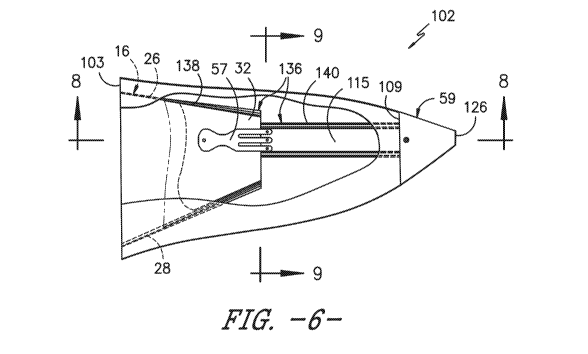
[0032] FIG. 6 illustrates a top detailed view of the single-piece tip
extension of
FIG. 5, particularly illustrating a transparent tip extension to further
illustrate the
internal components thereof;
[0033] FIG. 7 illustrates a perspective detailed view of the single-piece
tip
extension of FIG. 6;
[0034] FIG. 8 illustrates a perspective cross-sectional view of the single-
piece tip
extension of FIG. 5 along line 8-8;
[0035] FIG. 9 illustrates a cross-sectional view of the single-piece tip
extension
of FIG. 5 along line 9-9;
7
CA 03097518 2020-10-16
WO 2019/209313
PCT/US2018/029808
[0036] FIG. 10 illustrates a perspective view of one embodiment of the
conductive components configured within the tip extension of FIG. 5;
[0037] FIG. 11 illustrates a perspective view of one embodiment of a
conductive
extension configured within the tip extension of FIG. 5;
[0038] FIG. 12 illustrates a perspective view of one embodiment of a two-
piece
tip extension according to the present disclosure;
[0039] FIG. 13 illustrates a top detailed view of the two-piece tip
extension of
FIG. 12, particularly illustrating a transparent tip extension to further
illustrate the
internal components thereof;
[0040] FIG. 14 illustrates a perspective detailed view of the two-piece
tip
extension of FIG. 13;
[0041] FIG. 15 illustrates a perspective cross-sectional view of the two-
piece tip
extension of FIG. 13 along line 15-15;
[0042] FIG. 16 illustrates a side cross-sectional view of the two-piece
tip
extension of FIG. 13 along line 15-15;
[0043] FIG. 17 illustrates a partial perspective view of the tip extension
of FIG.
12, particularly illustrating the extended conductive blade tip connected to
the
conductive extension and extending from the second portion of the tip
extension;
[0044] FIG. 18 illustrates a partial perspective view of the tip extension
of FIG.
12, particularly illustrating the down-conductor member configured within a
recess of
the existing conductive blade tip with the conductive extension attached
thereto and
extending into the second portion of the tip extension;
[0045] FIG. 19 illustrates a partial perspective view of the second
portion of the
tip extension of FIG. 12, particularly illustrating an internal structural
channel
configured therein;
[0046] FIG. 20 illustrates a perspective view of the conductive components
configured within the tip extension of FIG. 12;
[0047] FIG. 21 illustrates a perspective view of another embodiment of a
two-
piece tip extension according to the present disclosure;
[0048] FIG. 22 illustrates a perspective detailed view of the two-piece
tip
extension of FIG. 21, particularly illustrating a transparent tip extension to
further
illustrate the internal components thereof;
8
CA 03097518 2020-10-16
WO 2019/209313
PCT/US2018/029808
[0049] FIG. 23 illustrates a partial perspective view of the tip extension
of FIG.
22, particularly illustrating the down-conductor member configured within a
recess of
the existing conductive blade tip with the conductive extension attached
thereto and
extending into the second portion of the tip extension;
[0050] FIG. 24 illustrates a side cross-sectional view of the single-piece
tip
extension of FIG. 22 along line 24-24;
[0051] FIG. 25 illustrates a detailed cross-sectional view of the
lightning receptor
of the tip extension of FIG. 22;
[0052] FIG. 26 illustrates a perspective view of the conductive components
configured within the tip extension of FIG. 22;
[0053] FIG. 27 illustrates a flow diagram of one embodiment of a method
for
installing a tip extension onto a tip end of a rotor blade of a wind turbine
according to
the present disclosure;
[0054] FIG. 28 illustrates a partial top view of one embodiment of a rotor
blade
of a wind turbine with a tip extension being slid onto the tip end of the
rotor blade
according to the present disclosure;
[0055] FIG. 29 illustrates is a partial top view of the embodiment of FIG.
28 after
the tip extension has been slid into position on the tip end of the rotor
blade;
[0056] FIG. 30 illustrates a partial top view of the embodiment of FIG. 29
depicting the release liners being peeled from tape strips through the
separated trailing
edge of the tip extension;
[0057] FIG. 31 illustrates a partial top view of the embodiment of FIG. 30
depicting the last release liner being peeled from tape strips through the
separated
trailing edge of the tip extension; and
[0058] FIG. 32 illustrates a flow diagram of another embodiment of a
method for
installing a tip extension onto a tip end of a rotor blade of a wind turbine
according to
the present disclosure.
DETAILED DESCRIPTION OF THE INVENTION
[0059] Reference now will be made in detail to embodiments of the
invention,
one or more examples of which are illustrated in the drawings. Each example is
provided by way of explanation of the invention, not limitation of the
invention. In
9
CA 03097518 2020-10-16
WO 2019/209313
PCT/US2018/029808
fact, it will be apparent to those skilled in the art that various
modifications and
variations can be made in the present invention without departing from the
scope or
spirit of the invention. For instance, features illustrated or described as
part of one
embodiment can be used with another embodiment to yield a still further
embodiment. Thus, it is intended that the present invention covers such
modifications
and variations as come within the scope of the appended claims and their
equivalents.
[0060] Referring now to the drawings, FIG. 1 illustrates a wind turbine 10
of
conventional construction. As shown, the wind turbine 10 includes a tower 12
with a
nacelle 14 mounted thereon. A plurality of blades 16 are mounted to a rotor
hub 18,
which is in turn connected to a main flange that turns a main rotor shaft (not
shown).
The wind turbine power generation and control components are housed within the
nacelle 14. The view of FIG. 1 is provided for illustrative purposes only to
place the
present invention in an exemplary field of use. It should be appreciated that
the
invention is not limited to any particular type of wind turbine configuration.
[0061] Referring to FIG. 2, a rotor blade assembly 100 for the wind
turbine 10 is
illustrated having a tip extension 102 attached to a surface 24 (e.g., suction
side
surface) of the rotor blade 16 according to the present disclosure. As shown,
the rotor
blade 16 has a pressure side 22 and a suction side 24 extending between a
leading
edge 26 and a trailing edge 28, and extends from a root end 34 to a tip end
32. The
rotor blade 16 further defines a pitch axis 40 relative to the rotor hub 18
(FIG. 1) that
typically extends perpendicularly to the rotor hub 18 and root end 34 through
the
center of the root end 34. A pitch angle or blade pitch of the rotor blade 16,
i.e., an
angle that determines a perspective of the rotor blade 16 with respect to the
air flow
past the wind turbine 10, may be defined by rotation of the rotor blade 16
about the
pitch axis 40. Further, the rotor blade assembly 100 defines a chord 42 and a
span 44.
For example, as shown in FIG. 2, the chord 42 may vary throughout the span 44
of the
rotor blade 16. Thus, a local chord may be defined for the blade 16 at any
point on
the blade 16 along the span 44.
[0062] Referring now to FIGS. 3 and 4, the rotor blade assembly 100 may
also
include a lightning protection system 50 configured therewith. For example, as
shown, schematic diagrams of various components of one embodiment of the
lightning protection system 50 are illustrated according to the present
disclosure.
CA 03097518 2020-10-16
WO 2019/209313
PCT/US2018/029808
More specifically, FIG. 3 illustrates a perspective view of one embodiment of
a
lightning protection system 50 configured with the wind turbine 10, whereas
FIG. 4
illustrates a cross-sectional view of one of the rotor blades 16 of the wind
turbine 10
having a portion of the lightning protection system 50 configured therein.
[0063] As shown, the lightning protection system 50 includes one or more
conductive circuits 52 configured at least partially within an internal cavity
36 of one
or more of the rotor blades 16 of the wind turbine 10. Further, as shown in
FIG 4,
each of the conductive circuits 52 may include one or more down conductors 55,
a
conductive blade tip 59, and at least one lightning receptor 54 located on
either of the
pressure or suction side surfaces 22, 24 of the rotor blade 16. For example,
as shown
in the illustrated embodiment, the down conductor(s) 55 of the lightning
protection
system 50 may include a down-conductor member 57 (e.g., a down-conductor fork
or
other suitable member), the down-conductor cable 56, or any other suitable
down
conductor. Further, as shown, the lightning receptors 54 are provided on both
of the
pressure and suction sides 22, 24. In an alternative embodiment, the lightning
receptors 54 may be provided on only one of the sides of the rotor blade 16.
It should
be understood that the lightning receptors 54 may be variously configured
within the
scope and spirit of the invention, and may include any metal or metalized
component
(i.e., a metal screen, a metal rod or tip, a metal fastener, and/or the like)
mounted on
the pressure and/or suction sides 22, 24 of the rotor blade 16 for the purpose
of
conducting lightning strikes to ground. In addition, as shown in FIG. 4, the
lightning
receptors 54 may be connected via one or more lightning conductors or
conductive
cables 56 configured within the internal cavity 36 of the rotor blade 16. As
such, the
conductive cables 56 may have a gauge suitable for defining a conductive leg
for
transmitting a lightning strike on any one of the receptors 54 to ground.
Further, the
conductive cable(s) 56 may be connected to an outer or inner surface of the
rotor
blade(s) 16. In addition, each of the rotor blades 16 may be configured in a
similar
manner.
[0064] Still referring to FIGS. 3 and 4, the respective lightning
conductive
circuits 52 for each of the rotor blades 16 may include terminal ends 58 that
extend
through the root end 34 of the rotor blades 16 and are individually connected
to a
grounding system 60 within the rotor hub 18. The grounding system 60 may be
11
CA 03097518 2020-10-16
WO 2019/209313
PCT/US2018/029808
variously configured, as is well known in the art. For example, the grounding
system
60 may include any conductive path defined by the wind turbine's machinery or
support structure, including blade bearings, machinery bed plates, tower
structure, and
the like, that defines any suitable ground conductive path 62 from the rotor
blades 16,
through the tower 12, to a ground rod 64 via a ground cable 72, or other
suitable
electrical ground path. In other embodiments, the conductive circuit 52 may be
defined by components that are embedded in the rotor blade 16, or are external
to the
rotor blade 16, for example along the outer surfaces 22, 24 of the rotor blade
16.
[0065] Referring particularly to FIG. 4, each rotor blade 16 may include a
single
conductive circuit 52, as depicted, with each of the lightning receptors 54
configured
in series within the single circuit 52. In an alternative embodiment, each of
the rotor
blades 16 may include a plurality of circuits 52, with each of the lightning
receptors
54 configured in one of the respective circuits 52. In still further
embodiments, the
receptors 54 may be connected in any suitable fashion via the conductive
cable(s) 56
and it should be understood that the embodiment of FIGS. 3 and 4 is provided
for
example purposes only and is not intended to be limiting.
[0066] Referring now to FIGS. 5-11, one embodiment of the tip extension
102 of
the present disclosure is illustrated according to the present disclosure.
More
specifically, the embodiment of FIGS. 5-11 illustrates a tip extension 102
that utilizes
the existing conductive blade tip 59 of the lightning protection system 50 at
its
outermost location. Further, as shown in FIG. 5, the tip extension 102 has a
generally
hollow body 108 having a first end 103, a second end 109, a closed leading
edge 104,
and a trailing edge 106 defined by separated pressure and suction side edges
105, 107
that are bonded together and extend chord-wise beyond the trailing edge 28 of
the
rotor blade 16 when mounted thereto. Moreover, the trailing edge 106 is
separated in
that the a suction side edge 105 and a pressure side edge 107 are not bonded
or sealed
together along at least part of the length of the trailing edge 106, which
allows the
pressure and suction sides of the tip extension 102 to be pulled apart to an
extent
necessary to slide the tip extension 102 onto the tip end 32 of the rotor
blade 16. In
certain embodiments as depicted in the figures, the trailing edge 106 is
separated
along essentially the entire length of the trailing edge, although this is not
a
requirement for all embodiments. Further, as shown in FIGS. 2 and 6-7, the
first end
12
CA 03097518 2020-10-16
WO 2019/209313
PCT/US2018/029808
103 of the tip extension 102 is configured to overlap the tip end 32 of the
rotor blade
16. As such, the rotor blade assembly 100 may also include an adhesive or one
or
more strips of a double-sided adhesive tape configured for securing the tip
extension
102 onto the tip end 32 of the rotor blade 16 when mounted thereto, which will
be
described in more detail below.
[0067] In additional embodiments, the tip extension 102 of the present
disclosure
may be formed using any suitable manufacturing processes. For example, in
certain
embodiments, the tip extension 102 described herein may be formed via three-
dimensional (3D) printing. As such, the tip extension 102 can be constructed
as a
single component or a limited number of components, such as two components
which
is described herein. 3D printing offers a number of advantages for the tip
extension
102, including but not limited to the ability to have an extension with a
solid and very
thin trailing edge at the outermost portion and a split trailing edge further
inboard to
aid in installation (which is described in more detail below). Further, 3D
printing of
the tip extension 102 provides an automated and economical manufacturing
process
that produces the desired shape that can be easily customized for various
lengths,
sizes, and internal geometry to match up to the existing blade surface for
bonding
with adhesives.
[0068] More specifically, as shown in FIGS. 6-9, the tip extension 102 can
be
easily designed with one or more internal structural components 136, including
for
example, a transition area structural support 138 and/or an internal
structural channel
140. As such, the structural component(s) 136 are configured to house and
electrically insulate the conductive components described herein. For example,
the
tip end 32 of the rotor blade 16 may be configured to fit within the
transition area
structural support 138, whereas the conductive extension 115 may be configured
to fit
within the internal structural channel 140. Further, the internal structural
components
136 of the tip extension 102 may contain internal ribs and/or additional
structure to
cradle the original tip end 32 of the rotor blade 16 for additional support.
[0069] Referring generally to FIGS. 6-11, the tip extension 102 also
includes a
conductive extension 115 configured between the first and second ends 103, 109
of
the tip extension 102. Thus, as shown in the illustrated embodiment, the
conductive
extension 115 is configured to electrically couple the down-conductor member
57 of
13
CA 03097518 2020-10-16
WO 2019/209313
PCT/US2018/029808
the lightning protection system 50 to the removable conductive blade tip 59.
More
specifically, as shown in FIG. 11, the conductive extension 115 may include a
first
end 117 and a second end 119. Further, as shown, the first end 117 of the
conductive
extension 115 may include side edges 121 that form a groove 123. Thus, as
shown in
FIG. 10, the down-conductor member 57 may be secured within the groove 123 of
the
conductive extension 115. Moreover, as shown in FIGS. 10-11, the second end
119
of the conductive extension 115 may be absent of the side edges 121 so that it
can be
secured within a recess 125 of the conductive blade tip 59. In addition, as
shown in
FIGS. 5-8, when the conductive blade tip 59 is secured to the second end 119
of the
conductive extension 115, the conductive blade tip 59 is also configured at
the second
end 109 of the tip extension 102 so as to provide an extended root end 126 of
the rotor
blade 16.
[0070] Referring now to FIGS. 12-20, another embodiment of a tip extension
102
according to the present disclosure is illustrated. More specifically, as
shown, the
embodiment of FIGS. 12-20 illustrates a tip extension 102 that maintains the
existing
conductive blade tip 59 as-is but rather attaches the conductive extension 115
and an
additional extended conductive blade tip 132 thereto to maintain the
functionality of
the lightning protection system 50. Like the embodiment illustrated in FIGS. 5-
11,
the tip extension 102 of FIGS. 12-20 has a generally hollow body 108 having a
first
end 103, a second end 109, a closed leading edge 104, and a trailing edge 106
defined
by separated pressure and suction side edges 105, 107 that are bonded together
and
extend chord-wise beyond the trailing edge 28 of the rotor blade 16 when
mounted
thereto. In contrast to the embodiment illustrated in FIGS. 5-11, however, the
tip
extension 102 has a two-piece body including a first portion 128 and a second
portion
130. Further, the down-conductor member 57 is secured within the recess 125 of
the
conductive blade tip 59 (i.e. rather than within the groove 123 of the
conductive
extension 115). Moreover, the first end 117 of the conductive extension 115 is
secured to the existing conductive blade tip 59 and the second end 119 of the
conductive extension 115 is secured to the extended conductive blade tip 132,
e.g. via
one or more fasteners 134 that may also be configured as lightning receptors.
[0071] Thus, as shown in the illustrated embodiment of FIGS. 12-20, the
conductive extension 115 is configured to electrically couple the existing
conductive
14
CA 03097518 2020-10-16
WO 2019/209313
PCT/US2018/029808
blade tip 59 to the extended conductive blade tip 132. In other words, the
existing
conductive blade tip 59 remains at the tip end 32 of the rotor blade 16 with
the tip
extension 102 mounted thereto. In such embodiments, the conductive blade tip
59
may be configured within the tip extension 102 between the first and second
ends
103, 109 thereof In addition, as shown in FIGS. 13-16, the first portion 128
may
cover the down-conductor member 57 and the conductive blade tip 59, whereas
the
second portion 130 may cover at least a portion of the conductive extension
115.
[0072] Referring specifically to FIGS. 13-16 and 18-19, as mentioned, the
tip
extension 102 may include one or more internal structural components 136. For
example, as shown, the internal structural components 136 include the
transition area
structural support 138 and the internal structural channel 140. As such, the
tip end 32
of the rotor blade 16 may be configured to fit within the transition area
structural
support 138, whereas the conductive extension 115 may be configured to fit
within
the internal structural channel 140.
[0073] In additional embodiments, the conductive components described
herein
may be formed of any suitable materials. For example, in certain embodiments,
the
conductive extension 115 and/or the conductive blade tip 59 may be constructed
of a
metal or metal alloy. More specifically, in particular embodiments, the metal
or metal
alloy may include aluminum.
[0074] Referring now to FIGS. 21-26, still another embodiment of a tip
extension
102 according to the present disclosure is illustrated. More specifically, as
shown, the
embodiment of FIGS. 21-26 illustrates a tip extension 102 that maintains the
existing
conductive blade tip 59 as-is but attaches the conductive extension 115
thereto having
at least one lightning receptor 134 to maintain the functionality of the
lightning
protection system 50. Like the embodiment illustrated in FIGS. 12-20, the tip
extension 102 has a generally hollow body 108 having a first end 103, a second
end
109, a closed leading edge 104, and a trailing edge 106 defined by separated
pressure
and suction side edges 105, 107 that are bonded together and extend chord-wise
beyond the trailing edge 28 of the rotor blade 16 when mounted thereto.
Further, like
the embodiment illustrated in FIGS. 12-20, the tip extension 102 has a two-
piece body
including a first portion 128 and a second portion 130. In addition, as shown,
the
down-conductor member 57 is secured within the recess 125 of the conductive
blade
CA 03097518 2020-10-16
WO 2019/209313
PCT/US2018/029808
tip 59. Moreover, the first end 117 of the conductive extension 115 is secured
to the
existing conductive blade tip 59. In contrast to the embodiment of FIGS. 12-
20,
however, the second end 119 of the conductive extension 115 includes at least
one
lightning receptor 134 that extends through a surface of the tip extension 102
(FIGS.
21-24) (rather than having the extended conductive blade tip 132 connected
thereto).
In such an embodiment, as shown in FIG. 25, the lightning receptor 134 may be
a
fastener that extends longer than, for example, the lightning receptors 134 of
FIGS.
13-16 and 18-20 that sit recessed within the tip extension 102.
[0075] In addition, as shown in FIGS. 21-23, the tip extension 102 may
include
one or more optional add-on components 142 configured between or with portions
of
the pressure and suction side edges 105, 107 of the separated trailing edge
106 and/or
with one or more surfaces of the tip extension 102. For example, as shown, the
add-
on component(s) 102 may include a serrated edge 144 (e.g. for noise
reduction), a
tape recess (e.g. for leading edge protection tape), an airflow modifying
element (such
as a vortex generator 146), a mounting feature (e.g. for an airflow modifying
element), a winglet, a weep hole 148, or any other suitable blade add-on
component
that may be mounted to or integral with the tip extension 102.
[0076] More specifically, if the pressure and suction side edges 105, 107
are not
offset, the add-on component 142 may be defined (e.g., by laser cutting) into
the
combination of the bonded surfaces 105, 107. In an alternate embodiment, to
reduce
the thickness of the add-on component 142, the feature may be defined in one
of the
edges 105, 107 that extend chord-wise beyond the other edge. For example, in
the
embodiment depicted in FIGS. 21-23, the suction side surface edge 105 of the
separated trailing edge 106 extends past the pressure side surface edge 107,
with the
add-on component 142 defined in the suction side surface edge 105 in the form
of a
serrated edge 144. It should be appreciated that the add-on component 142 is
depicted as a serrated profile for purposes of illustration only, and that any
design of
add-on component 142 is within the scope and spirit of the invention. In an
alternate
embodiment, the suction and pressure surface edges 105, 107 may extend equally
beyond the trailing edge 28 and the add-on component 142 may be bonded
therebetween.
[0077] Referring now to FIGS. 27-31, one embodiment of a method 200 for
16
CA 03097518 2020-10-16
WO 2019/209313
PCT/US2018/029808
installing the tip extension 102 of the present disclosure onto the tip end 32
of the
rotor blade 16 the wind turbine 10 is illustrated. As shown at 202, the method
200
includes removing the existing conductive blade tip 59 of the lightning
protection
system 50 so as to expose a down conductor 55 of the lightning protection
system 50.
For example, in certain embodiments, as mentioned, the down conductor 55
corresponds to the down-conductor member 57. In such embodiments, when the
conductive blade tip 59 is removed, the down-conductor member 57 is left
exposed.
[0078] Thus, as shown at 204, the method 200 also includes securing the
conductive extension 115 to the down conductor 55 (i.e. the down-conductor
57).
Moreover, as shown at 206, the method 200 includes sliding the first end 103
of the
tip extension 102 over the conductive extension 115 so as to overlap the rotor
blade
16 at the tip end 32 thereof For example, FIG. 28 illustrates one embodiment
of the
first end 103 of the tip extension 102 being slid over the tip end 32 of the
rotor blade
16. Further, the embodiment of FIGS. 28-31 is generally described in U.S.
Patent
Application Serial No.: 14/706,024 entitled "Attachment Method and System to
Install Components, such as Tip Extensions and Winglets, to a Wind Turbine
Blade,"
filed on May 7, 2015, which is incorporated herein by reference in its
entirety.
Although FIG. 28 depicts (by arrows) the tip extension 102 being slid linearly
in a
span-wise direction onto the rotor blade 16, it should be appreciated that
this sliding
motion may include a chord-wise direction component that is aided by the
separated
nature of the trailing edge 106. More specifically, in certain embodiments,
the step of
sliding the first end 103 of the tip extension 102 over the conductive
extension 115
may include inserting the tip end 32 of the rotor blade 16 into the transition
area
structural support 138 and inserting the conductive extension 115 into the
internal
structural channel 140.
[0079] In addition, as shown at 208, the method 200 includes securing the
conductive blade tip 59 to the conductive extension 115 at the second end 109
of the
tip extension 102. For example, in particular embodiments, the step of
securing the
conductive blade tip 59 to the conductive extension 115 at the second end 109
of the
tip extension 102 may include inserting the second end 119 of the conductive
extension 115 within the recess 125 of the conductive blade tip 59 and
securing one or
more fasteners through the conductive blade tip 59 and the second end 119 of
17
CA 03097518 2020-10-16
WO 2019/209313
PCT/US2018/029808
conductive extension 115.
[0080] Further, as shown at 210, the method 200 includes securing the tip
extension 102 to the rotor blade 16. More specifically, as shown in FIGS. 28-
31, the
step of securing the tip extension 102 to the rotor blade 16 may include
attaching an
adhesive side of one or more strips 110 of a double-sided adhesive tape onto
either or
both of pressure or suction side surfaces of the rotor blade 16 adjacent the
tip end 32
or onto interior surfaces of the tip extension 102 in any desired pattern or
configuration. It should be appreciated that a single, larger strip of tape
110 could
also be utilized in place of multiple strips. Although not depicted in the
figures, the
tape strips may also be adhered to the pressure side surface 22. The pattern
of the
tape strips 110 may be span-wise oriented and spaced-apart, as depicted in
FIG. 28. It
should be appreciated that the tape strips 110 may be applied to either or
both of the
blade surfaces 22, 24.
[0081] Further, as shown in FIGS. 28 and 29, the tape strips 110 have a
release
liner 112 on an opposite exposed side thereof and each of the tape strips 110
have an
extension tail 113 from the release liner 112 that extends beyond the first
end 103 of
the tip extension 102 when the tip extension 102 is slid onto the tip end 32
of rotor
blade 16. The length of the extension tails 113 may vary. For example, the
strips 110
furthest from the trailing edge 106 may have a longer extension tail 113 to
facilitate
pulling the extension tail 113 through the trailing edge 106, as compared to
the tape
strip 110 closest to the trailing edge 106. Alternatively, the extension tail
113 may
encompass any other material or component that is attached to the tape strip,
such as a
wire, string, ribbon, and so forth. With the illustrated embodiment, because
the
extension tails 113 are comprised of the release liner 112 and underlying
adhesive,
after removal of the release liner 112, the remaining adhesive layer of the
tape strips
adhesive 111 remains, as depicted in FIGS. 30 and 31, and may need to be
trimmed.
[0082] As such, the step of securing the tip extension 102 to the rotor
blade 16
may also include, with the tip extension 102 held in place, starting from the
tape strip
110 furthest from the separated trailing edge 106, sequentially pulling the
extension
tail 113 and release liner 112 of the respective tape strips 110 through the
separated
trailing edge 106 and away from the tip extension 102 at an angle such that
that the
release liner 112 is removed along the length of the tape strip 110 while
maintaining
18
CA 03097518 2020-10-16
WO 2019/209313
PCT/US2018/029808
position of tip extension 102 against the rotor blade 16 to attach the exposed
adhesive
110 from under the release liner 112 to either or both of the pressure or
suction side
surfaces of the rotor blade 16 or the interior surface of the tip extension
102 (FIGS.
29-31). Further, in the embodiment of FIG. 28, the tape strips 110 are
initially
adhered to the blade surface 24, wherein the tip extension 102 is subsequently
held or
otherwise maintained in the desired position on the rotor blade 16 (e.g., by
being
pressed against the tape strips 110) for subsequent removal of the release
liner 112
from between the underside of the tip extension 102 and the tape 110. It
should be
appreciated that there may be some degree of inherent "play" or movement of
the tip
extension 102 at the desired position on the rotor blade 16 as the release
liners 112 are
removed.
[0083] In an alternate embodiment, the tape strips 110 may be applied to an
interior surface of the tip extension 102 in the same pattern discussed above,
which is
then pressed against the blade surface 24, 22 for subsequent removal of the
release
liner 112 from the opposite side of the tape 110. It should be appreciated
that the
methods described herein may be implemented with a number of different
commercially available double-sided adhesive tapes. These tapes generally have
a
lower shear modulus than the tip extension 102 to allow for shear slippage
between
the tip extension 102 and the underlying blade surface. For example, the tape
strips
may be a foam-based strip member with adhesive on opposite interface sides
thereof,
such as a Very High Bond (VHBTM) or SAFT (Solar Acrylic Foam Tape) foam-based
strip material.
[0084] FIG. 28 also depicts an additional aspect that may be incorporated
into any
of the other embodiments described herein. In particular, an adhesive 116 is
depicted
as underlying the adhesive tape strips 110. In certain embodiments, it may be
desired
to coat the surface of the rotor blade 16 where the tip extension 102 will be
placed
with a liquid or paste adhesive (e.g., and epoxy) 116, for example to
compensate for
any surface irregularities or mismatch between the blade surface and the tip
extension
102 due, for example, to machining tolerances, before positioning the tape
strips 110
on the blade surface 24. The tape strips 110 and the tip extension 102 can
then be
attached before the adhesive 116 cures, which provides a degree of positioning
adjustment of the tip extension 102 due to the fact that the adhesive 116 is
still in
19
CA 03097518 2020-10-16
WO 2019/209313
PCT/US2018/029808
liquid or paste form. Alternatively, the adhesive 116 (with tape strips
attached
thereto) may be allowed to cure before placement of the tip extension 102. In
either
case, this particular embodiment also gives the advantage of a strong bond
provided
by the adhesive 116 in combination with the shear stress reduction provided by
the
tape strips 110.
[0085] In another embodiment, as mentioned, the separated trailing edge 106
may
include pressure and suction side edges 105, 107 that each extend past the
trailing
edge 28 of the rotor blade 16 to provide a chord-wise extension aspect to the
tip
extension 102. As such, the method 200 may also include bonding the pressure
and
suction side edges 105, 107 together subsequent to removal of the release
liners 112
and after attaching the tip extension 102 to the rotor blade 16. The edges
105, 107
may extend an equal chord-wise distance past the blade trailing edge 28, or
the edges
105, 107 may be offset in that one of the edges extends past the other. The
dashed
line indicating the pressure side surface edge 107 is meant to depict both of
these
configurations.
[0086] In further embodiments, as mentioned, the method 200 may include
locating one or more add-on components 142 (FIGS. 21-23) between portions of
the
pressure side and suction side edges 105, 107 of the separated trailing edge
106 and/or
to one or more surfaces of the tip extension 102.
[0087] Referring now to FIG. 32, a flow diagram of another embodiment of a
method 300 for installing the tip extension 102 onto the tip end 32 of the
rotor blade
16 of the wind turbine 10 is illustrated. More specifically, in particular
embodiments,
the method 300 of FIG. 32 can be applied to the tip extension 102 illustrated
in the
embodiment of FIGS 12-20. Thus, as shown at 302, the method 300 includes
securing the conductive extension 115 to the conductive blade tip 59. As shown
at
304, the method 300 includes sliding a first portion 128 of the tip extension
102 over
the conductive blade tip 59 so as to overlap the rotor blade 16 at the tip end
32
thereof As shown at 306, the method 300 includes sliding a second portion 130
of
the tip extension 102 over the conductive extension 115. As shown at 308, the
method 300 includes securing an extended conductive blade tip 132 to the
conductive
extension 115 such that extended conductive blade tip 132 extends beyond the
second
portion 130 of the tip extension 102. As shown at 310, the method 300 includes
CA 03097518 2020-10-16
WO 2019/209313
PCT/US2018/029808
securing the first portion 128 of the tip extension 102 to the rotor blade 16,
e.g. using
any suitable attachment methods (such as those illustrated in FIGS. 28-31). As
shown
at 312, the method 300 also includes securing the second portion 130 of the
tip
extension 102 to the first portion 128.
[0088] This written description uses examples to disclose the invention,
including the best mode, and also to enable any person skilled in the art to
practice the
invention, including making and using any devices or systems and performing
any
incorporated methods. The patentable scope of the invention is defined by the
claims,
and may include other examples that occur to those skilled in the art. Such
other
examples are intended to be within the scope of the claims if they include
structural
elements that do not differ from the literal language of the claims, or if
they include
equivalent structural elements with insubstantial differences from the literal
languages
of the claims.
21