Note: Descriptions are shown in the official language in which they were submitted.
CA 03097895 2020-10-20
WO 2019/212812 PCT/US2019/028831
DEVICES AND METHODS FOR CRIMPING PROSTHETIC IMPLANTS
FIELD
[001] The present application pertains generally to devices and related
methods for
crimping prosthetic implants, such as prosthetic heart valves.
BACKGROUND
[002] The human heart can suffer from various valvular diseases. These
valvular diseases
can result in significant malfunctioning of the heart and ultimately require
replacement of the
native valve with an artificial valve. There are a number of known artificial
valves and a
number of known methods of implanting these artificial valves in humans.
Because of the
drawbacks associated with conventional open-heart surgery, percutaneous and
minimally-
invasive surgical approaches are garnering intense attention. In one
technique, a prosthetic
heart valve is configured to be implanted in a much less invasive procedure by
way of
catheterization. For example, collapsible transcatheter prosthetic heart
valves can be
compressed or crimped and percutaneously introduced in the compressed state
with a
delivery apparatus and expanded to a functional size at the desired position.
[003] Such transcatheter prosthetic valves may be self-expandable or balloon-
expandable.
Balloon-expandable prosthetic valves are typically crimped from an initial
large diameter to a
smaller diameter prior to advancement to a treatment site in the body. Before
crimping, a
balloon expandable prosthetic valve is typically placed over an inflatable
balloon on a
catheter shaft. Once delivered to the implantation site, the balloon can be
inflated to expand
the prosthetic valve to its functional size. Self-expanding prosthetic valves
are typically also
crimped to a smaller diameter, but are then inserted into a sheath. After
placement in the
body, the sheath is retracted, and the prosthetic valve expands inside the
body.
SUMMARY
[004] Disclosed herein are exemplary embodiments of devices, systems and
related methods
for crimping a prosthetic implants onto a delivery apparatus, which can be
used to deliver the
crimped prosthetic implant to a deployment site within a body of a subject. In
some
implementations, the delivery apparatus can be used to deliver a prosthetic
implant through
the vasculature, such as to a heart of the subject.
- 1 -
CA 03097895 2020-10-20
WO 2019/212812 PCT/US2019/028831
[005] Certain embodiments of the disclosure concern an assembly including a
holder device
and a non-self-expandable prosthetic heart valve. The prosthetic heart valve
can be radially
compressed from an expanded configuration to a compressed configuration. The
holder
device can be configured to hold the prosthetic heart valve in the expanded
configuration and
to allow the prosthetic heart valve to be inserted in a crimping device so
that the prosthetic
heart valve can be crimped onto a valve mounting portion of a delivery
apparatus.
[006] In some embodiments, the holder device can include one or more retaining
members
configured to secure the prosthetic heart valve to the holder device when the
prosthetic heart
valve is in the expanded configuration and configured to release the
prosthetic heart valve
from the holder device when the prosthetic heart valve is compressed from the
expanded
configuration to the compressed configuration on the valve mounting portion of
the delivery
apparatus.
[007] In some embodiments, a distal portion of each retaining member can
extend distally
into the prosthetic heart valve when the prosthetic heart valve is in the
expanded
configuration. The distal portion of each retaining member can be disposed
proximal to the
prosthetic heart valve when the prosthetic heart valve is in the compressed
configuration.
[008] In some embodiments, each of the retaining members can have a protrusion
extending
radially outwardly at a distal end of the retaining member. Each protrusion
can be configured
to extend radially outwardly into an opening of the prosthetic heart valve
when the prosthetic
heart valve is in the expanded configuration.
[009] In some embodiments, the holder device can include a first portion and a
second
portion. The one or more retaining members can extend distally from the second
portion and
be axially moveable relative to a distal face of the first portion.
[010] In some embodiments, the prosthetic heart valve can elongate
unidirectionally when
the prosthetic heart valve is crimped from the expanded configuration to the
compressed
configuration such that the prosthetic heart valve can elongate distally while
the distal face of
the first portion prevents proximal elongation of the prosthetic heart valve.
[011] In some embodiments, the retaining members can be configured to extend
distally
relative to the distal face of the first portion for coupling to the
prosthetic heart valve in the
expanded configuration, and move proximally relative to the distal face of the
first portion
- 2 -
CA 03097895 2020-10-20
WO 2019/212812
PCT/US2019/028831
after releasing the prosthetic heart valve when the prosthetic heart valve is
radially
compressed.
[012] In some embodiments, when the prosthetic heart valve is held by the
holder device, a
proximal end portion of the prosthetic heart valve can abut the distal face of
the first portion
when the prosthetic heart valve is in the expanded configuration and is
secured to the holder
device by the retaining members.
[013] In some embodiments, the second portion of the holder device can include
one or
more sloped projections corresponding to the one or more retaining members,
and wherein
each sloped projection can interface with a sloped member on the corresponding
retaining
member such that the retaining members can slide distally into an interior
space of the
prosthetic heart valve when the prosthetic heart valve is in the expanded
configuration.
[014] In some embodiments, the holder device can include one or more biasing
members
configured to bias the second portion proximally relative to the first
portion.
[015] In some embodiments, the second portion can include one or more arms,
wherein a
distal end of each arm can extend distally relative to the distal face of the
first portion when
the retaining members are coupled to the prosthetic heart valve.
[016] In some embodiments, at least one arm can be circumferentially disposed
between a
pair of adjacent retaining members. The retaining members can extend radially
outwardly
relative to the arms when the prosthetic heart valve is in the expanded
configuration. The
retaining members can be compressed radially inwardly and radially align with
at least a
portion of the arms as the prosthetic heart valve is radially compressed.
[017] In some embodiments, the distal end of each arm can include a sloped
surface
configured to interface with a crimping jaw such that a radially inward
movement of the
crimping jaw can exert a force to the sloped surface and urge the
corresponding arm to move
proximally relative to the first portion.
[018] In some embodiments, the assembly can further include a positioning
device
configured to be releasably coupled to a shaft of the delivery apparatus and
to be releasably
coupled to the holder device.
- 3 -
CA 03097895 2020-10-20
WO 2019/212812 PCT/US2019/028831
[019] In some embodiments, the positioning device can include a body having an
interior
surface defining an axially extending passage that is sized to form an
interference fit with a
segment of the shaft.
[020] In some embodiments, the segment of the shaft can be located distally by
a predefined
distance relative to the valve mounting portion.
[021] In some embodiments, the inner surface of the body can include a row of
a plurality
of circumferentially oriented grooves extending from a proximal end of the
body to a distal
end of the body such that a sterilization gas can permeate into the passage
through the
plurality of grooves when the body is coupled to the shaft.
[022] In some embodiments, the holder device can include one or more first
coupling
members that are mateable with one or more second coupling members of the
positioning
device.
[023] In some embodiments, the assembly can further include the crimping
device. The
crimping device can be configured to radial compress the prosthetic heart
valve from the
expanded configuration to the compressed configuration. The holder device can
include one
or more third coupling members that are mateable with one or more fourth
coupling members
of the crimping device.
[024] Certain embodiments of the disclosure also concern a system for
prosthetic heart
valve implantation. The system can include a positioning and holder assembly
configured to
retain a prosthetic heart valve in an expanded configuration, be mounted on a
shaft of a
delivery apparatus, and allow insertion of the prosthetic heart valve into a
crimping device for
crimping the prosthetic heart valve from a radially expanded configuration to
a radially
compressed configuration onto a valve mounting portion of the delivery
apparatus.
[025] In some embodiments, the positioning and holder assembly can include a
positioning
portion configured to be releasably coupled to the shaft of the delivery
apparatus and a holder
portion configured to be releasably retain the prosthetic heart valve in the
radially expanded
configuration while the prosthetic heart valve is crimped onto the valve
mounting portion of
the delivery apparatus.
- 4 -
CA 03097895 2020-10-20
WO 2019/212812 PCT/US2019/028831
[026] In some embodiments, the positioning portion and the holder portion can
be separable
from each other.
[027] In some embodiments, the positioning portion and the holder portion can
be non-
separable from each other.
[028] In some embodiments, the holder portion can include one or more
retaining members
configured to secure the prosthetic heart valve to the holder portion when the
prosthetic heart
valve is in the expanded configuration and configured to release the
prosthetic heart valve
from the holder portion when the prosthetic heart valve is crimped from the
expanded
configuration to the compressed configuration on the valve mounting portion of
the delivery
apparatus.
[029] In some embodiments, a distal portion of each retaining member can
extend distally
into the prosthetic heart valve when the prosthetic heart valve is in the
expanded
configuration. The distal portion of each retaining member can be disposed
proximal to the
prosthetic heart valve when the prosthetic heart valve is in the compressed
configuration.
[030] In some embodiments, each of the retaining members can have a protrusion
extending
radially outwardly at a distal end of the retaining member. Each protrusion
can be configured
to extend radially outwardly into an opening of the prosthetic heart valve
when the prosthetic
heart valve is in the expanded configuration.
[031] In some embodiments, the holder portion can include a first portion and
a second
portion. The one or more retaining members can extend distally from the second
portion and
be axially moveable relative to a distal face of the first portion.
[032] In some embodiments, the prosthetic heart valve can elongate
unidirectionally when
the prosthetic heart valve is crimped from the expanded configuration to the
compressed
configuration such that the prosthetic heart valve can elongate distally while
the distal face of
the first portion prevents proximal elongation of the prosthetic heart valve.
[033] In some embodiments, the plurality of retaining members can be
configured to extend
distally relative to the distal face of the first portion for coupling to the
prosthetic heart valve
in the expanded configuration, and move proximally relative to the distal face
of the first
- 5 -
CA 03097895 2020-10-20
WO 2019/212812 PCT/US2019/028831
portion after releasing the prosthetic heart valve when the prosthetic heart
valve is radially
compressed.
[034] In some embodiments, when the prosthetic heart valve is held by the
holder portion, a
proximal end portion of the prosthetic heart valve can abut the distal face of
the first portion
when the prosthetic heart valve is in the expanded configuration and is
secured to the holder
portion by the plurality of retaining members.
[035] In some embodiments, the second portion can include a plurality of
sloped projections
corresponding to the plurality of retaining members. Each sloped projection
can interface
with a sloped member on the corresponding retaining member such that the
retaining
members can slide distally into an interior space of the prosthetic heart
valve when the
prosthetic heart valve is in the expanded configuration.
[036] In some embodiments, the holder portion can include one or more biasing
members
configured to bias the second portion proximally relative to the first
portion.
[037] In some embodiments, the second portion can include one or more arms. A
distal end
of each arm can extend distally relative to the distal face of the first
portion when the
retaining members are coupled to the prosthetic heart valve.
[038] In some embodiments, at least one arm can be circumferentially disposed
between a
pair of adjacent retaining members. The retaining members can extend radially
outwardly
relative to the arms when the prosthetic heart valve is in the expanded
configuration. The
retaining members can be compressed radially inwardly and radially align with
at least a
portion of the arms as the prosthetic heart valve is radially compressed.
[039] In some embodiments, the distal end of each arm can include a sloped
surface
configured to interface with a crimping jaw of the crimping device such that a
radially inward
movement of the crimping jaw can exert a force to the sloped surface and urge
the
corresponding arm to move proximally relative to the first portion.
[040] In some embodiments, the positioning portion can include a body having
an interior
surface defining an axially extending passage that is sized to form an
interference fit with a
segment of the shaft.
- 6 -
CA 03097895 2020-10-20
WO 2019/212812 PCT/US2019/028831
[041] In some embodiments, the segment of the shaft can be located distally by
a predefined
distance relative to the valve mounting portion.
[042] In some embodiments, the inner surface of the body can include a row of
a plurality
of circumferentially oriented grooves extending from a proximal end of the
body to a distal
end of the body such that a sterilization gas can permeate into the passage
through the
plurality of grooves when the body is coupled to the shaft.
[043] In some embodiments, the positioning and holder assembly can further
include one or
more coupling members that are mateable to one or more complimentary coupling
members
of the crimping device.
[044] Certain embodiments of the disclosure further concern a method of
crimping a
prosthetic heart valve onto a delivery apparatus. The method can include
coupling a
crimping device to a positioning and holder assembly mounted on a shaft of a
delivery
apparatus so that a prosthetic heart valve retained by the positioning and
holder assembly is
inserted into the crimping device, and actuating the crimping device to
radially compress the
prosthetic heart valve from an expanded configuration to a compressed
configuration and
onto a valve mounting portion of the delivery apparatus.
[045] In some embodiments, the method can further include coupling the
prosthetic heart
valve in the expanded configuration to the positioning and holder assembly.
[046] In some embodiments, the method can further include mounting the
positioning and
holder assembly to a predetermined location on the shaft of the delivery
apparatus. The
predetermined location can be spaced relative to the valve mounting portion of
the delivery
apparatus.
[047] In some embodiments, the positioning and holder assembly can include a
positioning
portion releasably coupled to the shaft of the delivery apparatus and a holder
portion
releasably retaining the prosthetic heart valve.
[048] In some embodiments, the act of mounting the positioning and holder
assembly can
include coupling the positioning portion to the predetermined location on the
shaft of the
delivery apparatus, and coupling the holder portion to the positioning device.
- 7 -
CA 03097895 2020-10-20
WO 2019/212812 PCT/US2019/028831
[049] In some embodiments, the act of actuating the crimping device can
release the
prosthetic heart valve from the positioning and holder assembly.
[050] In some embodiments, the compression of the prosthetic heart valve can
cause
unidirectional elongation of the prosthetic heart valve such that a proximal
end portion of the
prosthetic heart valve is fixedly aligned with a proximal end of the valve
mounting portion
and a distal end portion of the prosthetic heart valve extends distally during
the compression
until it aligns with a distal end of the valve mounting portion when the
prosthetic heart valve
is in the compressed configuration.
[051] In some embodiments, the method can further include decoupling the
positioning and
holder assembly from the delivery apparatus after the prosthetic heart valve
is crimped onto
the valve mounting portion.
[052] In some embodiments, the method can further include removing the
delivery
apparatus, together with the prosthetic heart valve, from the crimping device
after the
positioning and holder assembly is decoupled from the delivery apparatus.
[053] In some embodiments, the positioning and holder assembly can include one
or more
retaining members configured to releas ably couple to the prosthetic heart
valve. The
positioning and holder assembly can further include one or more arms. Each arm
can extend
distally into an interior space of the prosthetic heart valve when the
retaining members are
coupled to the prosthetic heart valve.
[054] In some embodiments, the act of actuating the crimping device can push
the one or
more retaining members radially inwardly so as to decouple the one or more
retaining
members from the prosthetic heart valve.
[055] In some embodiments, the act of actuating the crimping device can push
the one or
more arms proximally relative to and away from the prosthetic heart valve.
[056] Certain embodiments of the disclosure also concern a holder device for a
prosthetic
heart valve. The holder device can include one or more retaining members
configured to
secure a prosthetic heart valve to the holder device when the prosthetic heart
valve is in a
radially expanded configuration and configured to release the prosthetic heart
valve from the
- 8 -
CA 03097895 2020-10-20
WO 2019/212812 PCT/US2019/028831
holder device when the prosthetic heart valve is compressed with a crimping
device from the
radially expanded configuration to a radially compressed configuration.
[057] In some embodiments, each of the retaining members can have a protrusion
extending
radially outwardly at a distal end of the retaining member. Each protrusion
can be configured
to extend radially outwardly into an opening of the prosthetic heart valve
when the prosthetic
heart valve is in the expanded configuration.
[058] In some embodiments, a distal portion of each retaining member can
extend distally
into the prosthetic heart valve when the prosthetic heart valve is in the
expanded
configuration. The distal portion of each retaining member can be disposed
proximal to the
prosthetic heart valve when the prosthetic heart valve is in the compressed
configuration.
[059] In some embodiments, the holder device can further includes a valve
alignment
portion configured to secure the holder device to the crimping device. The
retaining
members can be movable relative to a distal face of the valve alignment
portion.
[060] In some embodiments, a proximal end portion of the prosthetic heart
valve can abut
the distal face of the valve alignment portion when the prosthetic heart valve
is in the
expanded configuration.
[061] In some embodiments, the holder device can further include one or more
biasing
members configured to bias the retaining members proximally relative to the
valve alignment
portion.
[062] In some embodiments, the holder device can further include one or more
arms. A
distal end of each arm can extend distally relative to the distal face of the
valve alignment
portion when the retaining members are coupled to the prosthetic heart valve.
[063] In some embodiments, at least one arm can be circumferentially disposed
between a
pair of adjacent retaining members. The retaining members can extend radially
outwardly
relative to the arms when the prosthetic heart valve is in the expanded
configuration. The
retaining members can be compressed radially inwardly and radially align with
at least a
portion of the arms as the prosthetic heart valve is radially compressed with
the crimping
device.
- 9 -
CA 03097895 2020-10-20
WO 2019/212812 PCT/US2019/028831
[064] In some embodiments, the distal end of each arm can include a sloped
surface
configured to interface with the crimping device such that, upon actuation of
the crimping
device, the crimping device can exert a force to the sloped surface and urge
the corresponding
arm proximally relative to the valve alignment portion.
[065] Further, certain embodiments of the disclosure concern a positioning
device for
positioning a prosthetic heart valve on a delivery apparatus. The positioning
device can
include a body and one or more coupling members that are mateable with one or
more
complementary coupling members of a prosthetic heart valve holder device. The
body can
include an interior surface defining an axially extending passage that is
sized to form an
interference fit with a shaft of the delivery apparatus.
[066] In some embodiments, the inner surface of the body can include a row of
a plurality
of circumferentially oriented grooves extending from a proximal end of the
body to a distal
end of the body such that a sterilization gas can permeate into the passage
through the
plurality of grooves when the body is coupled to the shaft.
[067] The various innovations of this disclosure can be used in combination or
separately.
This summary is provided to introduce a selection of concepts in a simplified
form that are
further described below in the detailed description. This summary is not
intended to identify
key features or essential features of the claimed subject matter, nor is it
intended to be used to
limit the scope of the claimed subject matter. The foregoing and other
objects, features, and
advantages of the disclosure will become more apparent from the following
detailed
description, which proceeds with reference to the accompanying figures.
BRIEF DESCRIPTION OF THE DRAWINGS
[068] FIG. 1 shows a perspective view of an exemplary prosthetic heart valve.
[069] FIG. 2 shows a perspective view of a positioning and holder device
assembly
mounted on a delivery apparatus, according to one embodiment.
[070] FIG. 3A shows a side elevation view of a delivery apparatus, according
to one
embodiment.
[071] FIG. 3B shows an enlarged view of the distal end portion of the delivery
apparatus of
FIG. 3A.
- 10 -
CA 03097895 2020-10-20
WO 2019/212812 PCT/US2019/028831
[072] FIG. 4A shows a perspective view of a crimping device, according to one
embodiment.
[073] FIG. 4B shows a prosthetic valve and the distal end portion of a
delivery apparatus
inserted into a crimping aperture of the crimping device of FIG. 4A.
[074] FIG. 5A is a perspective view showing a positioning device mounted at a
predetermined location of the delivery apparatus and a holder device with a
prosthetic valve
being placed on the delivery apparatus.
[075] FIG. 5B is a perspective view similar to FIG. 5A, after the holder
device is coupled to
the positioning device.
[076] FIG. 5C is a perspective view showing the holder device coupled to the
front face of
the crimping device.
[077] FIG. 5D is a perspective view showing the removal of the delivery
apparatus, together
with the prosthetic heart valve crimped thereon, from the holder device and
the crimping
device.
[078] FIG. 6 is a perspective view showing the positioning device being
removed from the
delivery apparatus.
[079] FIG. 7A shows a perspective view of a holder device, according to one
embodiment.
[080] FIG. 7B shows a distal perspective, exploded view of the holder device
of FIG. 7A.
[081] FIG. 7C shows a side perspective, exploded view of the holder device of
FIG. 7A.
[082] FIG. 8 shows a proximal perspective view of a holder device and a
coupled prosthetic
heart valve in the expanded configuration.
[083] FIG. 9A shows a distal end view of a holder device and a coupled
prosthetic heart
valve in the expanded configuration.
[084] FIG. 9B shows a distal end view of a holder device and a prosthetic
heart valve in a
compressed configuration.
- 11-
CA 03097895 2020-10-20
WO 2019/212812 PCT/US2019/028831
[085] FIG. 10 shows an enlarged view of a portion of the coupling interface
between a
prosthetic heart valve and a holder device, according to one embodiment.
[086] FIG. 11A shows the prosthetic heart valve coupled to a holder device,
according to
another embodiment.
[087] FIG. 11B shows a biasing mechanism in the holder device of FIG. 11A.
[088] FIGS. 12A and 12B is a cross-sectional view of a crimping device with a
prosthetic
valve and the distal end portion of a delivery apparatus inside of the
crimping device.
[089] FIG. 13 shows a perspective view of a container that includes an
assembly comprised
of a holder device and a prosthetic heart valve, according to another
embodiment.
[090] FIG. 14 shows a packaging assembly that contains a plurality of devices
that can be
used for implanting a prosthetic heart valve.
[091] FIG. 15A is a perspective view of another embodiment of a holder device
and a frame
of a prosthetic heart valve coupled to the holder device via a plurality of
valve retaining
members.
[092] FIG. 15B is a cross-sectional view of the frame and the holder device
depicted in FIG.
15A, wherein the plurality of valve retaining members are shown in valve-
engaging position.
[093] FIG. 15C is a cross-sectional view of the holder device depicted in FIG.
15A without
showing the frame, wherein the plurality of valve retaining members are shown
in valve-
releasing position.
[094] FIG. 15D is a cross-sectional view of the holder device depicted in FIG.
15A without
showing the frame, wherein the plurality of valve retaining members are shown
in stowed
position.
[095] FIG. 16A is a side perspective view of a valve retaining member,
according to another
embodiment.
[096] FIG. 16B is a front perspective view of an alternative embodiment of a
holder device
including a plurality of valve retaining members as depicted in FIG. 16A.
- 12-
CA 03097895 2020-10-20
WO 2019/212812 PCT/US2019/028831
[097] FIG. 16C is a front perspective view of a frame of a prosthetic heart
valve coupled to
the holder device depicted in FIG. 16B, according to one embodiment.
[098] FIG. 16D is a rear perspective view of the holder device and the frame
as depicted in
FIG. 16B, wherein the frame is decoupled from the holder device.
DETAILED DESCRIPTION
[099] For purposes of this description, certain aspects, advantages, and novel
features of the
embodiments of this disclosure are described herein. The disclosed methods,
apparatus, and
systems should not be construed as being limiting in any way. Instead, the
present disclosure
is directed toward all novel and nonobvious features and aspects of the
various disclosed
embodiments, alone and in various combinations and sub-combinations with one
another.
The methods, apparatus, and systems are not limited to any specific aspect or
feature or
combination thereof, nor do the disclosed embodiments require that any one or
more specific
advantages be present or problems be solved.
[0100] It should be noted at the outset that although prosthetic heart valves
are used as
exemplary collapsible prosthetic devices, the disclosed technology can be used
with various
other types of collapsible prosthetic devices such as stents and/or valve
repair devices.
[0101] For various reasons, a prosthetic heart valve can be stored and shipped
in its expanded
state. When a prosthetic heart valve for a transvascular implantation
procedure, the
prosthetic heart valve can be crimped onto a designated landing zone (also
referred to as a
"crimping area" or "valve mounting portion") of the delivery apparatus. In
many instances,
high precision and accuracy are required during crimping.
[0102] Precise and accurate alignment of the crimped prosthetic heart valve
with the
designated landing zone can be challenging, for example, because a prosthetic
heart valve
may elongate longitudinally during the crimping procedure. Moreover, the
crimping area can
be obscured from the user's view by the crimping jaws of the crimping device,
thus making it
difficult to see location of the prosthetic heart valve during the crimping
procedure.
[0103] Although occasionally a prosthetic heart valve may be crimped in a sub-
optimal
position, adjustment may be made by sliding it into place after it is crimped.
Such adjustment
- 13 -
CA 03097895 2020-10-20
WO 2019/212812 PCT/US2019/028831
is not recommended, due to possible damage to the leaflets of the prosthetic
heart valve. This
can even necessitate discarding the entire delivery system and the prosthetic
heart valve,
which is both expensive and wasteful.
[0104] In addition, particular care must be taken to ensure the prosthetic
heart valve is
oriented correctly on the delivery apparatus. For example, for a transfemoral
delivery
approach, the prosthetic valve is mounted on the delivery apparatus in a first
orientation (the
inlet of the prosthetic valve is mounted distally relative to the outlet for
implanting at the
aortic position), whereas for a transventricular approach, the prosthetic
heart valve is
mounted on the delivery apparatus in a second orientation (the outlet of the
prosthetic valve is
mounted distally relative to the inlet for implanting at the aortic position).
[0105] As a result, the crimping procedure usually needs to be performed by a
highly trained
clinical specialist and is time consuming. Thus, there is a need for improved
devices and
methods for faster, easier, and more accurate crimping of prosthetic heart
valves.
[0106] Disclosed herein are various devices and methods that can, for example,
make
crimping a prosthetic heart valve more accurate, easier, quicker, and/or more
repeatable. The
disclosed devices and methods can, among other things, reduce the level of
skill and/or
training required for personnel to perform the crimping procedure. This in
turn can reduce
costs associated with such procedures.
Prosthetic Heart Valve
[0107] FIG. 1 shows an exemplary prosthetic heart valve 10. The valve 10 can
have several
main components: a stent or frame 12, a valvular structure 14, and a skirt
assembly 16.
[0108] The frame 12 can have an annular shape and defines an inlet end 24 and
an outlet end
26 of the prosthetic heart valve. The valvular structure 14 can be configured
to permit blood
to flow through the prosthetic heart valve 10 in a direction from the inlet
end 24 to the outlet
end 26 of the prosthetic heart valve and to block the flow of blood through
the prosthetic
heart valve in a direction from the outlet end 26 to the inlet end 24. The
frame 12 can include
a plurality of struts 28 that collectively define a plurality of open cells 30
of the frame 12.
The valvular structure 14 can comprise one or more leaflets 18 (three in the
illustrated
embodiment), which can be made from natural tissue (e.g., pericardial tissue)
and/or any of
various synthetic materials.
- 14 -
CA 03097895 2020-10-20
WO 2019/212812 PCT/US2019/028831
[0109] The frame 12 can be made of any of various suitable plastically-
expandable materials
(e.g., stainless steel, cobalt-chromium alloys, etc.) or self-expanding
materials (e.g., Nitinol)
as known in the art. When constructed of a plastically-expandable material,
the frame 12
(and thus the valve 10) can be crimped to a radially compressed configuration
on a delivery
apparatus and then expanded inside a patient by an inflatable balloon or
another suitable
expansion mechanism. When constructed of a self-expandable material, the frame
12 (and
thus the valve 10) can be crimped to a radially compressed configuration and
restrained in the
compressed configuration by insertion into a sheath or equivalent mechanism of
a delivery
apparatus. Once inside the body, the valve can be advanced from the delivery
sheath, which
allows the valve to expand to its functional size.
[0110] The prosthetic heart valve 10 can be adapted to be implanted in the
native aortic
annulus and/or other native annuluses of the heart. Additional details
regarding prosthetic
heart valves can be found, for example, in U.S. Patent Nos. 9,393,110,
8,449,599, 7,999,394,
7,510,575, U.S. Patent Application Publication No. 2016/0317301, and U.S.
Patent
Application No. 15/664,430 (filed July 31, 2017), all of which are
incorporated by reference
herein.
Mounting Assembly
[0111] As shown in FIG. 2, the prosthetic heart valve 10 can be easily and
accurately
mounted to a delivery apparatus 50 using an exemplary mounting assembly 100.
The
mounting assembly 100 can comprise a positioning device 180 (also referred to
as an
alignment clip) that can be releasably mounted on or coupled to the delivery
apparatus 50.
The mounting assembly 100 can further comprise a holder device 110 that can be
releasably
coupled to the positioning device 180. In addition, the prosthetic heart valve
10 can be
releasably coupled to the holder device 110, which holds the prosthetic heart
valve at a
predetermined position and in a predetermined orientation relative to the
delivery apparatus
for crimping the prosthetic valve onto the delivery apparatus 50 when the
holder device is
coupled to the positioning device 180, as further described below.
[0112] As described more fully below, the mounting assembly 100 can further
comprise a
crimping device, such as the crimping device 160 (FIG. 4A). The holder device
110 can be
releasably coupled to the crimping device 160, and actuation of the crimping
device can
crimp the prosthetic heart valve 10 onto the delivery apparatus 50.
- 15 -
CA 03097895 2020-10-20
WO 2019/212812 PCT/US2019/028831
[0113] Referring to FIGS. 2 and 5A, the outflow end 26 of the prosthetic heart
valve 10 can
be coupled to or supported by the holder device 110. In other embodiments, the
inflow end
24 of the prosthetic heart valve 10 can be coupled to or supported by the
holder device 110.
It should be understood that the orientation of the prosthetic heart valve 10
will depend on the
delivery technique used to implant the prosthetic heart valve. FIG. 2 shows
the holder device
110 holding the outflow end 26 of the prosthetic valve positioned proximally
relative to the
inflow end 24 for delivering the prosthetic valve to the native aortic valve
in a transfemoral
delivery approach. Alternatively, the holder device 110 can hold the inflow
end 24 of the
prosthetic valve proximally relative to the outflow end 26 for delivering the
prosthetic valve
to the native aortic valve in a transventricular delivery approach.
[0114] Coupling the prosthetic heart valve 10 to the holder device 110 can,
for example,
occur as part of the manufacturing and/or packaging processes. Also as part of
the
manufacturing and/or packaging processes, the pre-coupled/pre-assembled
prosthetic heart
valve 10 and holder device 110 can be packaged with a delivery apparatus that
corresponds to
the orientation in which the prosthetic heart valve 10 is coupled to the
holder device 110
(e.g., a transfemoral delivery apparatus is packaged with the prosthetic valve
when prosthetic
heart valve is coupled to the holder device in the transfemoral orientation
shown in FIG. 2).
Hence, matching the orientation of prosthetic heart valve and the delivery
apparatus can, for
example, reduce or eliminate the potential procedural error of mounting the
prosthetic heart
valve 10 in the reverse, and thus incorrect, orientation relative to the
delivery apparatus (e.g.,
mounting a transfemorally oriented prosthetic heart valve on a
transventricular delivery
apparatus, or vice versa).
[0115] In particular embodiments, the positioning device 180 can be pre-
mounted on the
delivery apparatus at a predetermined location such that when holder device
110 is coupled to
the positioning device 180 (with the prosthetic heart valve 10 pre-coupled to
the holder
device 110) by the end user, the prosthetic heart valve 10 is precisely
aligned with respect to
a valve mounting portion of the delivery apparatus for subsequent crimping.
Thus, in this
manner, the assembly comprised of the holder device 110 and the prosthetic
heart valve 10
can be separately stored from the delivery apparatus (such as when the
prosthetic heart valve
is stored in a preservative solution), yet the end user can easily connect the
holder device 110
to the positioning device 110 in the operating theater, which automatically
positions the
prosthetic heart valve at the desired location relative to the delivery
apparatus for subsequent
- 16-
CA 03097895 2020-10-20
WO 2019/212812 PCT/US2019/028831
crimping just prior to implantation, thereby reducing procedure time and the
potential for
procedural error.
[0116] In particular embodiments, the pre-coupled/pre-assembled prosthetic
heart valve 10
and holder device 110 can be pre-coupled to the positioning device 180, which
in turn is pre-
mounted on a delivery apparatus in the final orientation and packaged together
in a sterile
package for shipment to the end user. In this manner, there is no need for the
end user (e.g., a
physician) to couple the holder device 110 to the positing device 180 or to
mount the
positioning device 180 on the delivery apparatus, thus further reducing
procedure time. Such
embodiments can be advantageous where the prosthetic heart valve need not be
stored
separately from the delivery apparatus in a preservative solution. For
example, a prosthetic
heart valve having so-called dry tissue leaflets are treated during the
manufacturing process
such that the prosthetic heart valve can be stored in a dry state (not
immersed in a
preservative solution).
[0117] In some embodiments, the holder device 110 and the positioning device
180 are not
separable components and instead comprise a single holder and positioning
device that is
configured to be mounted to a delivery apparatus and releasably hold a
prosthetic heart valve
10. Such embodiments can be used, for example, where the prosthetic heart
valve can be
stored in a dry state. The holder and positioning device can be pre-mounted on
the delivery
apparatus and the prosthetic heart valve can be pre-coupled to the holder and
positioning
device and all three components can be contained in the same sterile package
for shipping
and storage. The holder and positioning device can include a holder portion
configured to
hold a prosthetic valve and a positioning portion configured to be mounted on
the delivery
apparatus.
[0118] As used herein, the terms "pre-coupled" or "pre-assembled" or "pre-
mounted" means
that two components are coupled or assembled together or one component is
mounted on the
other by the manufacturer prior to being placed in packaging and shipped from
the
manufacturer to a distributor or end user (e.g., a hospital).
[0119] To further aid in accurately pairing the prosthetic heart valve and the
delivery
apparatus, one or more of the components can be color coded with colored
indicia or other
types of visual indicia representative of the delivery technique to be used
for implanting the
prosthetic valve. For example, a holder device 110 can be a first color (e.g.,
red) when a
- 17 -
CA 03097895 2020-10-20
WO 2019/212812 PCT/US2019/028831
prosthetic heart valve is coupled thereto for transfemoral delivery, and a
delivery apparatus
and/or a positioning device configured for transfemoral delivery can also be
the same first
color. As another example, a holder device 110 can be a second color (e.g.,
green) when a
prosthetic heart valve is coupled thereto for transventricular delivery, and
the delivery
apparatus and/or the positioning device configured for transventricular
delivery can also be
the same second color. In this manner, the color coding can help an assembler
and/or a user
select and/or ensure that the prosthetic heart valve and delivery apparatus
are accurately
paired.
Delivery Apparatus
[0120] FIGS. 3A and 3B shows the delivery apparatus 50, according to one
embodiment.
The delivery apparatus 50 can comprise a handle 52 and an outer shaft 58
extending distally
therefrom. The delivery apparatus 50 can also comprise an inner shaft 60
extending distally
from the handle 52 and coaxially through the outer shaft 58. The inner shaft
60 can be
referred to as an implant catheter because a prosthetic heart valve can be
mounted onto the
inner shaft for delivery into a patient's body. In some embodiments, the inner
shaft 60 can be
movable relative to the outer shaft 58 (i.e., the inner shaft can be rotated
and/or moved axially
relative to the outer shaft, or vice versa).
[0121] The delivery apparatus 50 can further have a nose cone 64 coupled to
the distal end
portion of the inner shaft 60. The inner shaft 60 can have a valve mounting
portion (or
designated landing zone) 62 that is located adjacent and proximal to the nose
cone 64. The
valve mounting portion 62 can have a proximal end 68 and a distal end 66. The
axial length
L of the valve mounting portion 62 measured between the proximal end 68 and
the distal end
66 can be approximately equal to the axial length of the prosthetic heart
valve 10 when it is
fully crimped onto the implant catheter 60. The delivery apparatus 50 can also
have proximal
and distal stops 74 and 76, respectively, mounted on the inner shaft 60, with
the space
between the proximal and distal stops defining the valve mounting portion. The
proximal
stop 74 can be mounted to the distal end portion 59 of the outer shaft and/or
to the outer
surface of the inner shaft 60. The distal stop 76 can be formed as the
proximal end portion of
the nose cone 64, although in other embodiments it may be separately formed
and affixed to
the nose cone and/or the outer surface of the inner shaft 60.
- 18 -
CA 03097895 2020-10-20
WO 2019/212812 PCT/US2019/028831
[0122] Although not shown, a guide wire can extend through a central lumen of
the inner
shaft 60 and an inner lumen of the nose cone 64, so that the delivery
apparatus 50 can be
advanced over the guide wire which is inserted into a patient's vasculature.
[0123] The handle 52 can be configured to position and/or manipulate the outer
shaft 58.
For example, the handle 52 can include an actuation mechanism (e.g., a
rotatable knob) that
is configured to cause the outer shaft 58 to rotate about and/or slide along
its longitudinal axis
relative to the inner shaft 60.
[0124] The distal part of the delivery apparatus 50 can include a steerable
section 56 having
sufficient flexibility so that it can pass through tortuous anatomy without
sacrificing rigidness
of the outer shaft 58. In addition, the delivery apparatus 50 can include one
or more pull
wires (not shown) configured to cause the steerable section 56 to curve in a
given direction,
or to straighten.
[0125] For example, a pull wire can extend through a lumen in the outer shaft
58. A distal
end of the pull wire can be fixedly secured to the distal end portion 59 of
the outer shaft 58.
A proximal end of the pull wire can be operatively connected to a steering
mechanism (e.g.,
such as the illustrated rotatable knob 78, a button, etc.) located on the
handle 52. Actuating
the steering mechanism can increase or decrease tension on the pull wire,
which in turn can
cause the steerable section 56 to bend or straighten.
[0126] In some embodiments, the terminal distal end 80 of the outer shaft 58
can be
positioned to be proximal and immediately adjacent the proximal stop 74 so as
to minimize
the overall length of the relatively stiffer distal straight section of the
delivery apparatus
(which includes the valve mounting portion 62, the proximal and distal stops
74, 76, and the
nose cone 64), thereby improving the tracking performance of the delivery
apparatus 50. In
some embodiments, the distal end of the pull wire can be secured to the outer
shaft 58 at or
slightly proximal of the terminal distal end 80 of the outer shaft to maximize
the overall
length of the steerable section 56.
[0127] The embodiment shown in FIGS. 3A and 3B has an inflatable balloon 54
mounted on
the inner shaft 60, overlying the valve mounting portion 62. The proximal end
portion 54p of
the balloon 54 can extend over the proximal stop 74 and can be secured to the
outer surface
- 19-
CA 03097895 2020-10-20
WO 2019/212812 PCT/US2019/028831
of the distal end portion 59 of the outer shaft 58. The distal end portion 54d
of the balloon 54
can extend over the distal stop 76 and can be secured to the outer surface of
the nose cone 64.
[0128] As depicted, the balloon 54 can have a proximal shoulder 67, a distal
shoulder 65,
and an intermediate portion 69 disposed between the shoulders 65, 67. The
proximal
shoulder 67 can be approximately aligned with the proximal end 68 of the valve
mounting
portion 62, and the distal shoulder 65 can be approximately aligned with the
distal end 66 of
the valve mounting portion 62. Both the proximal shoulder 67 and the distal
shoulder 65 of
the balloon 54 can taper radially outwardly from respective ends of the
intermediate portion
69 to the proximal and distal stops 74, 76, respectively, so as to define a
generally dog bone-
shaped balloon 54. In this manner, the proximal and distal shoulders define
ramped surfaces
of the balloon.
[0129] The balloon 54 can be fluidly coupled to an inflation fluid conduit
(not shown) of the
outer shaft 58 which extends to a port 53 located on the handle 52 so that,
when an inflation
fluid (e.g., saline) is supplied to the balloon 54 via the port 53 and the
inflation fluid conduit,
the balloon 54 can be inflated from a collapsed configuration to an expanded
configuration.
[0130] In some embodiments, a prosthetic heart valve 10 can be crimped on the
balloon 54
which overlies the valve mounting portion 62. Thus, at the implantation site,
the balloon 54
can be inflated to expand the prosthetic heart valve 10 to its fully
functional size. The
ramped shoulders 67 and 65 can, for example, facilitate smooth expansion of
the prosthetic
heart valve 10 and maintain the positioning of the prosthetic heart valve
relative to the
balloon 54 during expansion. The ramped shoulders can also facilitate easier
retrieval of the
balloon 54 after the implantation.
[0131] In other embodiments (not shown), a self-expanding prosthetic heart
valve can be
crimped and inserted into a sheath of a delivery apparatus. After placement in
the body, the
sheath can be withdrawn and the prosthetic heart valve can expand inside the
body.
[0132] Additional details regarding delivery apparatuses can be found, for
example, in U.S.
Patent No. 9,339,384 and U.S. Patent Application Publication No. 2017/0065415,
both of
which are incorporated by reference herein.
- 20 -
CA 03097895 2020-10-20
WO 2019/212812 PCT/US2019/028831
Crimping Device
[0133] FIG. 4A shows a crimping device 160, according to an exemplary
embodiment. The
crimping device 160 can have a window or opening 172 exposing a plurality of
jaws 170,
which are arranged around a central axis 171 of the jaws 170. The jaws 170 can
define a
variable-sized crimping aperture 174 between their inner ends. The jaws 170
can be located
within a rotating portion comprising a housing 176 and operatively connected
to an actuator
in the form of a lever or handle 177 connected to and extending from the
housing 176.
[0134] The crimping device 160 can further include a frame 178 which can act
as a stand or
base. The crimping device 160 can include a coupling mechanism that is
configured to
releasably couple to the holder device 110. For example, in the embodiment
depicted in FIG.
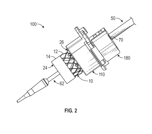
4A, a proximal or front surface 166 of the frame 178 can have one or more
catches 168 (e.g.,
three in the illustrated embodiment) which are configured to matingly engage
with one or
more corresponding tabs of the holder device 110, as described more fully
below. As shown,
the catches 168 can protrude radially outwardly relative to the window 172.
The catches 168
can also be circumferentially distributed around the window 172.
[0135] FIG. 4A shows the crimping aperture 174 in an "open" position, with the
jaws 170
moved to their radially outward positions such that the aperture 174 has a
relatively large
diameter. In the "open" position, an expanded annular implant (e.g., the
prosthetic heart
valve 10) can be inserted into the crimping aperture 174.
[0136] FIG. 4B shows the prosthetic heart valve 10 and the valve mounting
portion 62 of the
delivery apparatus 50 inserted into the crimping aperture 174. Actuating the
crimping device
160, e.g., by pressing the lever 177 downwardly, moves the crimping aperture
174 from the
"open" to a "closed" or constricted position. When moved to the closed
position by the lever
177, the jaws 170 move radially inwardly toward each other so as to decrease
the size of the
crimping aperture 174 and compress the prosthetic heart valve onto the valve
mounting
portion 62 of the delivery apparatus 50.
[0137] Exemplary embodiments of crimping devices and the associated crimping
methods
are further described in U.S. Patent Application Publication Nos.
2015/0336150,
2015/0190225, 2013/0030418, and U.S. Patent No. 7,993,394, the disclosures of
which are
incorporated by reference herein.
- 21 -
CA 03097895 2020-10-20
WO 2019/212812 PCT/US2019/028831
Mounting Process
[0138] FIG. 5A-5D illustrate a method of crimping the prosthetic heart valve
10 on the
delivery apparatus 50, according to one exemplary embodiment. The prosthetic
heart valve
is shown in an expanded configuration in FIGS 5A-B, and in a compressed
configuration
in FIG. 5D. Generally, the prosthetic heart valve 10 in the compressed
configuration has a
longer axial dimension and a smaller radial cross-sectional dimension than in
the expanded
configuration.
[0139] As shown in FIG. 5A, the prosthetic heart valve 10 can be coupled to
the holder
device 110 to form a valve and holder device assembly. The positioning device
180 can be
coupled to the outer shaft 58 of the delivery apparatus 50 at a predetermined
location. For
example, a proximal end of the positioning device 180 can be aligned with a
marker 70 (FIG.
5B) on the outer shaft 58 and secured to the outer shaft 58 against
inadvertent movement
(rotational and axial movement) relative to the outer shaft. The marker 70 can
be spaced
relative to the valve mounting portion 62 of the implant catheter 60. The
axial distance D
between the marker 70 and the proximal end 68 of the valve mounting portion 62
can be
predetermined to align the prosthetic heart valve with the valve mounting
portion 62, as
further detailed below.
[0140] As shown in FIG. 5B, the valve and holder device assembly can be
positioned over
the delivery apparatus 50 and coupled to the positioning device 180. The
positioning of the
positioning device 180 relative to the delivery catheter 50 can be configured
so as to align the
prosthetic heart valve 10 relative to the delivery apparatus 50. For example,
the proximal end
portion of the holder device 110 can be releasably coupled to a distal end of
the positioning
device 180. Because the location of the positioning device 180 on the delivery
apparatus 50
is predetermined, the location of the prosthetic heart valve 10 (which is
coupled to the holder
device 110) on the delivery apparatus 50 can also be predetermined.
Specifically, when the
holder device 110 is coupled to the positioning device 180, the proximal end
of the prosthetic
heart valve 10 can be aligned with the proximal end 68 of the valve mounting
portion 62.
[0141] With the positioning device, the holder device and the prosthetic valve
mounted on
the delivery apparatus as shown in FIG. 5B, the prosthetic heart valve 10 and
the delivery
apparatus 50 can then be inserted into the crimping device 160, as shown in
FIG. 5C. The
holder device 110 (together with the positioning device 180) can be coupled to
the crimping
- 22 -
CA 03097895 2020-10-20
WO 2019/212812 PCT/US2019/028831
device 160, so as to align the prosthetic heart valve 10 relative to the
crimping jaws 170 of
the crimping device 160.
[0142] When so coupled to the crimping device, the engagement of the holder
device 110
with the catches 168 on the crimping device is effective to place the
prosthetic valve 10 at a
desired location within the crimping aperture 174 and retain the prosthetic
heart valve and the
delivery apparatus against movement relative to the crimping device. As noted
above, the
positioning device 180 retains the holding device 110 and the prosthetic valve
110 at a fixed
location relative to the delivery apparatus. Thus, when the holding device is
coupled to the
crimping device as shown in FIG. 5C, the prosthetic valve 10 is held at a
desired location
along the delivery apparatus within the crimping device for subsequent
crimping of the
prosthetic valve at the valve mounting portion 62. Advantageously, the user
need not have to
manually position the prosthetic valve relative to the crimping jaws and the
valve mounting
portion 62 and hold those positions while operating the crimping device.
[0143] The crimping device 160 can then be used to crimp the prosthetic heart
valve 10 onto
the delivery apparatus 50, as shown in FIG. 5D. As described more fully below,
actuating the
crimping device 160 can release the prosthetic heart valve 10 from the holder
device 110. In
addition, actuating the crimping device 160 can radially compress the
prosthetic heart valve
from the expanded configuration to the compressed configuration. Because the
crimped
prosthetic heart valve 10 has a reduced radial cross-sectional dimension and
is decoupled
from the holder device 110, the delivery apparatus 50, together with the
prosthetic heart valve
10 crimped thereon, can then be removed from the mounting assembly 100.
[0144] Additional details of these components and various methods for using
the components
are further described below.
Positioning Device
[0145] FIG. 6 shows one exemplary embodiment of the positioning device 180. As
shown,
the positioning device 180 in the illustrated embodiment can include a body
181 having a
clam-shell configuration comprising a first portion 182 and a second portion
184 that are
hingedly connected to each other by a hinge member 186. The first and second
portions 182,
184 can be pivoted relative to each other between an open position (shown in
FIG. 6) and a
closed position (FIG. 5C). The positioning device 180 can also include a
fastening or
-23 -
CA 03097895 2020-10-20
WO 2019/212812 PCT/US2019/028831
latching mechanism, shown generally at 183, configured to retain the body 181
in the closed
position while mounted on the delivery apparatus 50.
[0146] The body 181 can have an interior surface 185 defining a central
passage or lumen
188 that receives the outer shaft of the the delivery apparatus 50. The
central passage 188
can be sized to form an interference or frictional fit with a segment 72 of
the outer shaft 58
that is adjacent and distal to the marker 70. In particular embodiments, when
the body 181 is
in a closed position around the segment 72, the interference fit with the
segment 72 is
sufficient to hold the positioning device stationary against rotational and
axial movement
relative to the shaft during normal use and handling.
[0147] It should be noted that the marker 70 can be an annular shoulder or
ridge or can be a
line or another type of visual indicia formed or printed on the shaft 58. In
the illustrated
embodiment, the segment 72 can have a reduced outer diameter compared to the
portion of
the shaft 58 proximal to the segment 72 so as to define an annular shoulder 70
that can abut
an adjacent surface of the positioning device 180 and prevent axial movement
of the
positioning device in the proximal direction along the outer shaft 58.
[0148] In the closed configuration (e.g., FIGS. 2 and 5A-C), the first and
second portions 182
and 184 are held in the closed position by the fastening mechanism 183 such
that the segment
72 of the outer shaft 58 is completely surrounded by the body 181.
[0149] In the depicted embodiment, the fastening mechanism 183 includes an
outwardly
extending protrusion 183b (FIG. 5D) located on the inner surface of the first
portion 182
opposite the hinge member 186, and an inwardly extending protrusion 183a (FIG.
5D)
located on the inner surface of the second portion 184 opposite the hinge
member 186. The
protrusions 183a, 183b can be complementarily shaped and sized to form a snap-
fit
connection with each other. Thus, the first and second portions 182, 184 can
be placed in the
closed configuration by urging the protrusion 183a against the protrusion 183b
until the
protrusion 183a slides over the protrusion 183b and engages an adjacent
surface thereof, as
shown in FIG. 5C. When closing the positing device, the second portion 184 can
deflect or
deform slightly to allow the protrusion 183a to pass over the protrusion 183b,
and then
reverts back to its original shape to hold the second portion 184 in the
closed position relative
to the first portion 182. To open the positioning device 180, the second
portion 184 can be
pried away from the first portion 182 to allow the protrusion 183a to pass
back over the
- 24 -
CA 03097895 2020-10-20
WO 2019/212812 PCT/US2019/028831
protrusion 183b as the second portion 184 is pivoted toward the open position.
In alternative
embodiments, various other types of fastening mechanisms can also be used to
retain the first
and second portions 182, 184 in the closed position, such as clips, hooks,
locks, keys, claps,
snaps, buttons, buckles, zippers, hook-and-loop fasteners, magnets, etc.
[0150] As further shown in FIG. 5D, the inner surface 185 of the body 181 can
include one
or more grooved paths 191 extending from a proximal end 190 of the body 181 to
a distal end
192 of the body 181. Each grooved path 191 can have a plurality of axially
spaced,
circumferentially oriented grooves 194 formed on the interior surface 185.
Although two
grooved paths 191 are shown in FIGS. 5D and 6 (one on the inner surface of the
first portion
182 and one on the inner surface of the second portion 184), it should be
understood that the
body 181 can have any number of grooved paths 191 that are circumferentially
disposed on
the inner surface 185. When the positioning device is closed, grooves on the
first portion 182
can align with respective grooves on the second portion 184 such that each
groove on the first
portion 182 is paired with a respective groove on the second portion 184 to
define a full
groove that extends through 360 degrees along the inner surface 185 of the
body 181.
[0151] Because the grooved paths 191 create a void space on the inner surface
185 and they
extend through the body 181, a sterilization gas can permeate or flow into the
central passage
188 through the grooved paths 191 even as the body 181 is coupled to the outer
shaft 58 and
in the closed position. Thus, both the inner surface 185 of the positioning
device 180 and the
outer surface of the outer shaft 58 extending therethrough can be sterilized
by the sterilization
gas when the positioning device 180 is coupled to the delivery apparatus 50.
For example,
after the prosthetic valve and the components of the mounting assembly are
removed from
their packaging by the end user and assembled on the delivery apparatus as
shown in FIG. 5B
(if any components are not already pre-assembled or pre-mounted), the
prosthetic valve, the
delivery apparatus 50, and the mounting assembly can be exposed to an ethylene
oxide
sterilization process (or another sterilization gas) if re-sterilization of
any of these
components is deemed necessary prior to implantation.
[0152] In alternative embodiments, one or more of the grooves 194 can be
replaced by one or
more slots that extend through the body 181 from the outer surface to the
inner surface 185.
In the closed configuration, the slots allow the sterilization gas to permeate
or flow into the
central passage 188 for sterilization.
- 25 -
CA 03097895 2020-10-20
WO 2019/212812 PCT/US2019/028831
[0153] In addition, the positioning device 180 can have a flange 196 connected
to the first
portion 182 adjacent the distal end 192 of the body 181. The flange 196 can
have a larger
radial diameter than the body 181. In certain embodiments, one or more tabs
198 can project
radially outwardly from the outer edge of the flange 196. The flange 196
and/or tabs 198 can
be used, for example, to couple the positioning device 180 to the holder
device 110, as further
discussed below.
Coupling Mechanisms
[0154] FIGS. 5A-5D further illustrate the manner in which the holder device
110 is coupled
to the positioning device 180 and the holder device 110 is coupled to the
crimping device
160.
[0155] For example, as shown in FIG. 5A, the proximal end of the holder device
110 can
have a flange 116, which can be configured to be releasably coupled to the
flange 196 of the
positioning device 180. The flange 116 of the holder device 110 can be
configured to be
releasably coupled to the crimping device 160.
[0156] In certain embodiments, the flange 116 of the holder device 110 can
have one or more
catches 118 protruding axially outwardly from the proximal face of the flange
116. The
catches 118 of the holder device can have interior recesses that are
complementary to the one
or more tabs 198 located on the flange 196 of the positioning device 180. In
other words, the
catches 118 of the holder device 110 can be are so sized, shaped, and
positioned as to be
capable of matingly engaging with the corresponding tabs 196 of the
positioning device 180.
[0157] As best shown in FIG. 5C, each catch 118 can span an arc
circumferentially, and have
an open end 114 and a closed end 115 opposite the open end 114. The catches
118 can be
sequentially arranged such that the open ends 114 and the close ends 115 of
the catches 118
are juxtaposed circumferentially. Thus, coupling or uncoupling between the
holder device
110 and the positioning device 180 can be accomplished by placing the flange
116 of the
holder device 110 against the flange 196 of the positioning device 180 with
the tabs 198 of
the positioning device adjacent the open ends 114 of the catches 118 of the
holding device,
and then coaxially rotating the holder device 110 relative to the positioning
device 180 to
position the tabs 198 within respective catches 118.
- 26 -
CA 03097895 2020-10-20
WO 2019/212812 PCT/US2019/028831
[0158] For example, the holder device 110 can be coupled to the positioning
device 180 by
rotating the holder device 110 in one direction (e.g., clockwise) so that the
tabs 198 can be
inserted through the open ends 114 and into the interior recesses of the
catches 118, while the
insertion can be limited by the close ends 115 of the catches 118. Conversely,
uncoupling
between the holder device 110 and the positioning device 180 can be achieved
by rotating the
holder device 110 in the opposite direction (e.g., counter-clockwise) so that
the tabs 198 can
exit through the open ends 114.
[0159] In particular embodiments, the catches 118 can be sized and shaped to
form an
interference or frictional fit with the tabs 198 that is sufficient to hold
the positioning device
and the holding device together and prevent relative movement between the two
components
during normal use and handling. In some embodiments, the catches 118 and/or
the tabs 198
can include additional features to help retain the positioning device and the
holding device
together, such as protrusions formed on one component and corresponding
detents formed on
another component that receive the protrusions.
[0160] In certain embodiments, the flange 116 of the holder device 110 can
further include
one or more tabs 119 protruding radially outwardly from the outer edge of the
flange 116. As
noted above, the front surface 166 of the crimping device 160 can have one or
more catches
168 protruding axially outwardly from the proximal face of the crimping device
160. The
catches 168 of the crimping device can have interior recesses that are
complementary to the
one or more tabs 119 located on the flange 116 of the holder device 110. In
other words, the
catches 168 of the crimping device 160 can be are so sized, shaped, and
positioned as to be
capable of matingly engaging with the corresponding tabs 119 of the holder
device 110.
[0161] In some embodiments, each tab 119 can be a generally flat protrusion or
extension of
the flange 116 (e.g., FIGS. 5A-5D). In other embodiments, each tab 119 can
comprise a
cantilevered arm extending outwardly from the flange 116 (e.g., FIGS. 7A-7C).
In addition,
the tabs 119 and/or the catches 168 can include additional features to help
retain the holder
device 110 and the crimping device 160 together. For example, as illustrated
in FIGS. 7A-
7C, each tab 119 can comprise a small hump or protrusion 117 protruding
outwardly from the
cantilevered arm. The hump 117 can be configured to engage with a
complimentary arranged
detent (not shown) formed on the corresponding catch 168 of the crimping
device to help
retain the holder device 110 on the crimping device 160.
- 27 -
CA 03097895 2020-10-20
WO 2019/212812 PCT/US2019/028831
[0162] As best shown in FIGS. 5C and 5D, each catch 168 can span an arc
circumferentially,
and have an open end 164 and a closed end 165 opposite the open end 164. The
catches 168
can be sequentially arranged such that the open ends 164 and the close ends
165 of the
catches 168 are juxtaposed circumferentially. Thus, coupling or uncoupling
between the
crimping device 160 and the holder device 110 can be accomplished by placing
the flange
166 of the holder device 110 against the front face 166 of the crimping device
160 with the
tabs 119 adjacent the open ends 164 of the catches, and then coaxially
rotating the holder
device 110 relative to the crimping device 160.
[0163] For example, coupling between the holder device 110 and the crimping
device 160
can be achieved by rotating the holder device 110 in one direction (e.g.,
clockwise) so that
the tabs 119 can be inserted through the open ends 164 and into the interior
recesses of the
catches 168, while the insertion can be limited by the closed ends 165 of the
catches 168.
Conversely, uncoupling between the holder device 110 and the crimping device
160 can be
achieved by rotating the holder device 110 in the opposite direction (e.g.,
counter-clockwise)
so that the tabs 119 can exit through the open ends 164.
[0164] In particular embodiments, the catches 168 can be sized and shaped to
form an
interference or frictional fit with the tabs 119 that is sufficient to hold
the holder device 110
on the crimping device 160 and prevent relative movement between the two
components
during normal use and handling. In some embodiments, the catches 168 and/or
the tabs 119
can include additional features to help retain the holding device on the
crimping device 160,
such as protrusions (e.g., protrusions 117) formed on one component and
corresponding
detents formed on another component that receive the protrusions.
[0165] In alternative embodiments, the holder device 110 may not have
independent sets of
catches 118 and tabs 119. For example, the holder device 110 can have one or
more
integrated coupling members (not shown), each of which can be configured to
function both
as a catch for a corresponding tab 198 on the positioning device 180 and as a
tab for a
corresponding catch 168 on the crimping device 160. In other words, the
integrated coupling
members on the holder device 110 can be configured to matingly engage the tabs
198 on the
positioning device 180, as well as the catches 168 on the crimping device 160.
[0166] In alternative embodiments (not shown), the relative positions of the
corresponding
catches and tabs can be switched. For example, the positioning device 180 can
have one or
- 28 -
CA 03097895 2020-10-20
WO 2019/212812 PCT/US2019/028831
more catches that are capable to matingly engage with one or more tabs located
on the holder
device 110. Likewise, the crimping device 160 can have one more tabs that are
capable to
matingly engage with one or more catches located on the holder device 110.
[0167] Further, although FIGS. 5A-5D show that the complementarily configured
tabs and
catches are used to implement the coupling mechanisms between the holder
device 110 and
the positioning device 180, and between the crimping device 160 and the holder
device 110,
it should be understood that the depicted embodiments are merely for
illustration purpose and
not limiting. Other coupling mechanisms, such as clips, hooks, locks, keys,
claps, snaps,
buttons, buckles, zippers, hook and loop fasteners, magnets, etc., can also be
employed,
independently or in combination, to achieve coupling between the holder device
110 and the
positioning device 180, and between the crimping device 160 and the holder
device 110.
Holder Device
[0168] The holder device 110 is configured to hold the prosthetic heart valve
10 in the
expanded configuration and to allow the prosthetic heart valve 10 to be
inserted in the
crimping device 160 so that the prosthetic heart valve 10 can be crimped onto
the valve
mounting portion 62 of the delivery apparatus 50.
[0169] In some embodiments, the holder device 110 can include one or more
retaining
members configured to secure the prosthetic heart valve 10 to the holder
device 110 when the
prosthetic heart valve 10 is in the expanded configuration and configured to
release the
prosthetic heart valve 10 from the holder device 110 when the prosthetic heart
valve 10 is
compressed with the crimping device from the expanded configuration to the
compressed
configuration.
[0170] Although embodiments of the holder device 110 described below include a
valve
alignment portion a valve retaining portion that are arranged in a specific
structural
configuration, it should be understood that other structural configurations
are also possible to
achieve the same function, and they are also within the scope of this
disclosure. For example,
in some embodiments, the valve alignment portion can be placed inside the
valve retaining
portion. In some embodiments, the valve alignment portion and the valve
retaining portion
can be an integrated piece and need not be separable from each other. In some
embodiments,
the retaining members can be located on any part of the holder device 110. In
some
- 29 -
CA 03097895 2020-10-20
WO 2019/212812 PCT/US2019/028831
embodiments, each of the retaining members can comprise an axially extending,
telescoping
beam that can be extending and retracted in an axial direction in a
telescoping manner.
[0171] Referring now to FIGS. 7A-7C, the holder device 110 can include a first
portion (also
referred to as a "valve alignment portion") 120 and a second portion (also
referred to as a
"valve retaining portion") 140. As described below, the valve retaining
portion 140 can be
coaxially inserted into the valve alignment portion 120. Further, the valve
retaining portion
140 can move proximally or distally relative to the valve alignment portion
120 along a
central axis 112.
[0172] As shown in FIG. 7B, the valve retaining portion 140 can comprise a
proximal plate
150 which can have a generally cylindrical shape, except for having a cavity
152 extending
from an outer periphery 154 of the plate through the central axis 112. The
cavity 152 can
have a width that is narrower near the central axis 112 (e.g., inner width W2)
and wider near
the periphery (e.g., outer width W2').
[0173] The valve retaining portion 140 can further comprise a plurality of
valve retaining
members 142a, 142b, 142c, collectively referred to as retaining members 142
(three are
shown). The valve retaining portion 140 can also include a plurality of
extension arms 146a,
146b, 146c, 146d, collectively referred to as arms 146 (e.g., four are shown),
which extend
axially from the distal surface of the plate 150. As shown in FIG. 7A, each
retaining member
142 can comprise a cantilevered beam 145 which extends axially from the distal
surface of
the plate 150 and a protrusion 144 which extends radially outwardly from a
distal end portion
of the beam 145. The retaining members 142 are configured to releasably hold
the prosthetic
valve 10 on the holder device 110, as further described below. The arms 146
are configured
to engage the crimping jaws 170 of the crimping device 160, which produces
movement of
the valve retaining portion 140 relative to the valve alignment portion 120
during the
crimping process, allowing the retaining members 142 to disengage from the
prosthetic heart
valve 10, as further described below.
[0174] The plurality of retaining members 142 can be circumferentially
positioned relative to
each other in a generally uniform pattern. For example, FIGS. 7A-7C shows
three retaining
members 142 spaced circumferentially apart from each other by about 120
degrees. Two of
the retaining members 142a, 142c can be symmetrically located on opposite
sides of the
-30-
CA 03097895 2020-10-20
WO 2019/212812 PCT/US2019/028831
cavity 152, and the third retaining member 142b can be located diametrically
opposite the
cavity 152.
[0175] The plurality of arms 146 can be circumferentially positioned relative
to each other in
a generally uniform pattern. For example, FIGS. 7A-C shows four arms 146
spaced
circumferentially apart from each other by about 90 degrees. The four arms 146
can be
located generally symmetric about the cavity 152 (i.e., two arms 146a, 146b
are located on
one side, and two arms 146c, 146d are located on opposite side of the cavity
152).
[0176] In some embodiments, at least one arm 146 is circumferentially disposed
between a
pair of adjacent retaining members 142. For example, in the depicted
embodiments, two
arms 146a, 146d near the upper edge of the cavity 152 are located between two
retaining
members 142a, 142c, one arm 146b is located between the retaining members 142a
and 142b,
and one arm 146c is located between the retaining members 142b and 142c.
[0177] As shown in FIG. 7C, the valve alignment portion 120 can comprise a
body 130 and a
flange 116 connected to the proximal end of the body 130. The body 130 can
have a
generally cylindrical shape, except for having a cavity 132 extending from an
outer periphery
134 of the body 130 through the central axis 112. Referring to FIG. 7B, the
cavity 132 can
have a width that is narrower near the central axis 112 (e.g., inner width W1)
and wider near
the periphery (e.g., outer width W1').
[0178] Generally, referring to FIG. 7B, the diameter D1 of the body 130 of the
valve
alignment portion 120 can be larger than the diameter D2 of the proximal plate
150 of the
valve retaining portion 140. On the other hand, the width of the cavity 132 of
the valve
alignment portion 120 can be smaller than the width of the cavity 152 on the
valve retaining
portion 140 (e.g., W1 <W2 and W1' <W2') so that the valve retaining portion
140 can be
inserted into the valve alignment portion 120 as shown in FIG.8.
[0179] Referring again to FIGS. 7C and 8, the body 130 of the valve alignment
portion 120
can define a hollow interior space 136 opening to the proximal face of the
body. The interior
space 136 can be sized and shaped to accommodate the valve retaining portion
140, including
the retaining members 142, the arms 146, and the proximal plate 150. As
illustrated in FIG.
8, with a proper alignment between the cavity 152 of the valve retaining
portion 140 and the
cavity 132 of the valve alignment portion 120, the valve retaining portion 140
can be
-31 -
CA 03097895 2020-10-20
WO 2019/212812 PCT/US2019/028831
configured to slide into and/or out of the hollow interior space 136 through a
proximal
opening in the front face of the body 130.
[0180] The body 130 can further have a distal face 122 defining a wall of the
hollow interior
space 136. As shown, the distal face 122 can include a plurality of apertures
124 (e.g., four
apertures 124a, 124b, 124c, and 124d are shown) that are respectively sized,
shaped and
positioned to receive the distal end portions of the plurality of arms 146 of
the valve retaining
portion 140. In addition, the body 130 can further include a plurality of
auxiliary apertures
126 (e.g., three auxiliary apertures 126a, 126b, and 126c are shown) that are
respectively
sized, shaped and positioned to receive the distal end portions of the
plurality of retaining
members 142 of the valve retaining portion 140.
[0181] The auxiliary apertures 126 can be adjacent to and proximally recessed
relative to the
distal face 122. The auxiliary apertures 126 can be radially longer than the
plurality of
apertures 124. Each of the auxiliary apertures 126 can extend from the outer
periphery 134
into the cavity 132 of the body 130.
[0182] The circumferential position of the apertures 124 and the auxiliary
apertures 126 are
configured to generally match the circumferential position of the
corresponding arms 146 and
the retaining members 142, respectively.
[0183] For example, the plurality of apertures 124 can be circumferentially
positioned
relative to each other in a generally uniform pattern. As shown in FIG. 7B,
four apertures
124 can be circumferentially spaced apart from each other by about 90 degrees,
and the four
apertures 124 can be located generally symmetrically about the cavity 132
(i.e., two apertures
124a, 124b are located on one side and two apertures 124c, 124d are located on
opposite side
of the cavity 132).
[0184] Similarly, the plurality of auxiliary apertures126 can be
circumferentially positioned
relative to each other in a generally uniform pattern. As shown, three
auxiliary apertures 126
can be circumferentially spaced apart from each by about 120 degrees. Two of
the auxiliary
apertures 126a, 126c can be symmetrically located on opposite sides of the
cavity 132, and
the third auxiliary aperture 126b can be located diametrically opposite the
cavity 132.
[0185] In certain embodiments, the distal face 122 can further include a
plurality of recesses
128, each of which can extend from the outer periphery 134 into the cavity 132
of the body
-32-
CA 03097895 2020-10-20
WO 2019/212812 PCT/US2019/028831
130. As depicted in FIG. 7B, for example, two recesses 128 can be
symmetrically located on
opposite sides of the third auxiliary aperture 126b, each forming an angle of
about 60 degrees
with the third auxiliary aperture 126b.
[0186] With a proper alignment, the valve retaining portion 140 can be
inserted into the valve
alignment portion 120 such that the plurality of arms 146 can extend through
the
corresponding apertures 124 and the plurality of retaining members 142 can
extend through
the corresponding auxiliary apertures 126, as shown in FIG. 7A. Thus, distal
movement of
the valve retaining portion 140 relative to the valve alignment portion 120
can push the distal
end portions of the arms 146 and the distal end portions of the retaining
members 142 distally
relative to the distal face 122 of the valve alignment portion 120.
Conversely, proximal
movement of the valve retaining portion 140 relative to the valve alignment
portion 120 can
withdraw the distal end portions of the arms 146 and the distal end portions
of the retaining
members 142 proximally relative to the distal face 122 of the valve alignment
portion 120.
[0187] Although the embodiments depicted in FIGS. 7A-C show four arms 146 (and
four
corresponding apertures) as well as three retaining members 142 (and three
corresponding
auxiliary apertures 126), it should be understood that any number of arms (and
the
corresponding apertures) and any number of retaining members (and the
corresponding
auxiliary apertures) can be used. Further, the arms (and the corresponding
apertures) and the
retaining members (and the corresponding auxiliary apertures) need not be
equally
circumferentially spaced from each other.
Valve-Holder Interface
[0188] As noted above, a radially expandable and compressible prosthetic
implant can be
releasably coupled to the holder device 110. Specifically, a prosthetic
implant, such as the
prosthetic heart valve 10, can be releasably coupled to the valve retaining
portion 140 and
positioned distally relative to the valve alignment portion 120 of the holder
device 110.
[0189] For example, FIGS. 8 and 9A show different views of the holder device
110 holding
the prosthetic heart valve 10 in an expanded configuration. FIG. 9B shows the
holder device
110 after the prosthetic heart valve 10 is removed from the holder device 110
and crimped
onto the balloon 54 of the delivery apparatus 50.
- 33 -
CA 03097895 2020-10-20
WO 2019/212812 PCT/US2019/028831
[0190] When the prosthetic heart valve 10 is in the expanded configuration,
the diameter DE
of the prosthetic heart valve 10 can be generally larger than the inner width
W1 of the cavity
132 (see, e.g., FIG. 9A). Thus, the holder device 110 can prevent the proximal
movement of
the prosthetic heart valve 10 when it is in the expanded configuration.
However, when the
prosthetic heart valve 10 is in the compressed configuration, the diameter Dc
of the prosthetic
heart valve 10 can be smaller than the inner width W1 of the cavity 132 (see,
e.g., FIG. 9B).
Thus, after crimping, the delivery apparatus 50, together with the prosthetic
heart valve 10
crimped thereon, can be withdrawn proximally out of the holder device 110
through the
cavity 132.
[0191] In some embodiments, the holder device 110 can comprise a biasing
mechanism that
biases the valve retaining portion 140 proximally relative to the valve
alignment portion 120.
In one example, FIG. 8 shows two biasing members 138 located on the valve
retaining
portion 140 interfacing with respective adjacent surfaces located on the valve
alignment
portion 120, which can be in the form of piston members 148.
[0192] When the retaining members 142 are coupled to the prosthetic heart
valve 10, the
biasing members 138, such as spring plates or bias springs, can be preloaded
and exert a
biasing force against the contacting piston members 148. When the retaining
members 142
are pushed inwardly by the crimping jaws 170 relative to the prosthetic heart
valve 10, the
biasing force from the biasing members 138 moves the valve retaining portion
proximally
relative to the valve alignment portion so as to move the retaining arms
proximally out of the
prosthetic valve. The biasing mechanism can be implemented by means of any
mechanical
and/or non-mechanical means, such as the electro-magnetic repelling force
generated
between two magnets with like poles (not shown). In addition, any number of
biasing
members can be employed in the holder device. The biasing members can also be
separate
components from the valve alignment portion 120 and the valve retaining
portion 140.
[0193] FIG. 10 shows an enlarged view of a portion of the coupling interface
between the
prosthetic heart valve 10 and the holder device 110, according to one
embodiment. The
prosthetic heart valve 10 is shown in the expanded configuration defining an
interior space
35.
[0194] As described above, each retaining member 142 can comprise a protrusion
144 which
extends radially outwardly from the distal end portion of the beam 145. Each
of the
- 34-
CA 03097895 2020-10-20
WO 2019/212812 PCT/US2019/028831
cantilevered beams 145 can be preloaded or biased to the outward direction.
Thus, each of
the protrusions 144 can extend from the interior space 35 of the prosthetic
heart valve 10,
through a portion of the prosthetic heart valve, to a location outside of the
prosthetic heart
valve 10 when the prosthetic heart valve 10 is in the expanded configuration.
In this manner,
the retaining members 142 can hook the prosthetic heart valve 10 onto the
holder device 110.
[0195] In some embodiments, each protrusion 144 can comprise a base portion
144b which
joins the distal end portion of the beam 145 and a head portion 144h that
projects radially
outwardly relative to the base portion 144b. In some embodiments, the base
portion 144b can
have a proximal surface 144v that extends radially outwardly and generally
perpendicular to
the beam 145. In some embodiments, the head portion 144h can have a proximal
sloped
surface 144s which tilts or curves toward a tip portion 144t. The proximal
sloped surface
144s can extend from the proximal vertical surface 144v to the tip portion
144t.
[0196] In some embodiments, the base portion 144b can have a larger
longitudinal
dimension WD than the tip portion 144t. In some embodiments, the protrusion
144 can have
a generally tapered shape such that its longitudinal dimension WD
progressively decreases
from the base portion 144b to the tip portion 144t.
[0197] As shown in FIG. 10, the proximal end portion of the prosthetic heart
valve 10 can be
defined by a plurality of proximal nodes or apices 38 of the frame 12, each of
which can be
formed at the intersection of two circumferentially adjacent angled struts 28
of the frame. As
shown, each protrusion 144 can extend radially outwardly through an adjacent
open cell 30.
In addition, the beams 145 can be preloaded such that they are biased radially
outward
against the inner surface of the frame 12. Thus, the retaining members 142 in
the illustrated
embodiment can securely hold the frame 12 (and thus the prosthetic valve) on
the holding
device via the outward biasing force of the retaining members as well as by
the protrusions
144 hooking onto the struts of the frame at selected apices 38.
[0198] As described above, one or more biasing members can be incorporated
into the
holder device 110 so as to bias the valve retaining portion 140 proximally
relative to the
valve alignment portion 120. Also, the proximal surface 144v of the base
portion 144b can
engage an adjacent proximal node 38 and two angled struts 28 intersecting at
that node 38.
As such, the biasing members urge the retaining members 142 proximally, which
in turn urge
the frame 12 against the distal face 122 of the valve alignment portion 120.
- 35 -
CA 03097895 2020-10-20
WO 2019/212812 PCT/US2019/028831
[0199] As shown in FIG. 10, at least some of the proximal nodes 38 (e.g., 38a)
are in direct
contact with the distal face 122 of the valve alignment portion 120 of the
holder device 110.
Thus, despite the force (in the proximal direction) applied to the frame 12 by
the protrusion
144, the distal face 122 can block proximal movement of the frame 12 so long
as the
prosthetic heart valve 10 is not in the compressed configuration (note: in the
compressed
configuration, all proximal nodes 38 are located within the cavity 132 because
the diameter
of the prosthetic heart valve 10 is smaller than the inner width of the cavity
132, as noted
above.) Nonetheless, the force applied by the retaining members 142 can keep
those
proximal nodes 38a in contact with the distal face 122.
[0200] In some embodiments, some of the proximal nodes 38 (e.g., 38b) may be
aligned
with the cavity 132, the auxiliary apertures 126, or the recesses 128, such
that they do not
directly contact the distal face 122. Nonetheless, all proximal nodes 38a, 38b
can be
generally coplanar with the distal face 122.
[0201] As shown in FIG. 10, each arm 146 of the holder device 110 can comprise
a sloped
surface 147 along the distal end portion of the arm 146. The sloped surface
147 can be
oriented to face partially outwardly in the radial direction and partially
distally in the axial
direction. When the prosthetic heart valve 10 is in the expanded
configuration, at least an
inner portion 147i of the sloped surface 147 can extend into the interior
space 35 of the
prosthetic heart valve 10. In addition, an outer portion 147o of the sloped
surface 147 can be
located radially outward relative to the frame 12, as well distal relative to
the distal face 122
of the valve alignment portion 120.
[0202] In some embodiments, the retaining members 142 can extend radially
outwardly
relative to the arms 146 when the prosthetic heart valve 10 is in the expanded
configuration.
For example, the tip portion 144t of the protrusion 144 can extend radially
outwardly relative
to the sloped surface 147 (including the outer portion 147o) of the arm 146
when the
prosthetic heart valve 10 is in the expanded configuration.
[0203] When the prosthetic heart valve 10 is crimped from the expanded
configuration to the
compressed configuration with the crimping device 160, the jaws 170 of the
crimping device
160 press the retaining members 142 of the holder device 110 radially inwardly
into the
interior space 35 of the prosthetic heart valve 10. The jaws 170 also move the
arms 146 and
thus the valve retaining portion 140 axially proximally relative to the
prosthetic heart valve
- 36 -
CA 03097895 2020-10-20
WO 2019/212812 PCT/US2019/028831
until the retaining members 142 are withdrawn from the prosthetic valve.
Continued
movement of the jaws 170 crimps the prosthetic valve onto the delivery
apparatus. In this
manner, the prosthetic heart valve is released from the valve holder 110 as
the crimping
device 160 is actuated. This process is further described below.
[0204] FIG. 11A shows the prosthetic heart valve 10 coupled to another
embodiment of a
holder device 210, which has a similar structure and valve-interface as the
holder device 110.
For example, the holder device 210 can also comprise the valve alignment
portion 120 and
the valve retaining portion 140 as shown in FIGS. 7A-7C, except for some
additional features
as described below.
[0205] As shown in FIG. 11A, the holder device 210 can include a ramped
interface for each
of the retaining members 142. Specifically, the valve alignment portion 120 of
the holder
device 210 can include a plurality of inwardly extending sloped projections
260. Each sloped
projection 260 can be positioned radially outward relative to a corresponding
retaining
member 142. Each sloped projection 260 can have a sloped inner surface 262
which is
oriented to face partially radially inwardly and partially axially proximally.
[0206] Correspondingly, each retaining member 142 can have a sloped protrusion
264
adjacent a corresponding projection 260. Each sloped protrusion 264 can have a
sloped outer
surface 266 which is oriented to face partially radially outwardly and
partially axially distally.
The sloped outer surface 266 can be complementarily positioned, sized, and
shaped relative
to the corresponding sloped inner surface 262 of an adjacent projection 260.
Thus, the sloped
projection 260 can be configured to interface with the corresponding sloped
protrusion 264
by a sliding engagement between the sloped inner surface 262 and the sloped
outer surface
266.
[0207] The holder device 210 can also include a biasing mechanism that biases
the valve
retaining portion 140 proximally relative to the valve alignment portion 120.
FIG. 11B
shows an alternative embodiment of the biasing mechanism, where a biasing
member 238
located on the valve alignment portion 120 of the holder device 210 interfaces
with a
corresponding piston member 248 located on the valve retaining portion 140 of
the holder
device 210. When the retaining members 142 are coupled to the prosthetic heart
valve 10,
the biasing member 238 is pushed distally to a loaded position by the piston
member 248.
When the retaining members 142 are released from the prosthetic heart valve
10, the biasing
- 37 -
CA 03097895 2020-10-20
WO 2019/212812 PCT/US2019/028831
member 238 returns to its unloaded position and pushes the piston member 148
in the
proximal direction.
[0208] To mount the prosthetic heart valve 10 to the holder device 210, the
valve retaining
portion 140 can be moved distally relative to the valve alignment portion 120.
Due to the
ramped interfaces between the retaining members 142 and the corresponding
sloped
projections 260, the distal end portions of the retaining members 142
(including the
protrusions 144) move radially inwardly so that they can be easily inserted
into the interior
space 35 of the prosthetic heart valve 10 when the prosthetic heart valve 10
is in the
expanded configuration. Then, as the cantilevered beams 145 tilt outwardly and
return
toward their preloaded positions, the protrusions 144 can "grab" the
prosthetic heart valve 10
by extending from the interior space 35 of the prosthetic heart valve 10,
through an opening
of the frame 12, to a location outside of the prosthetic heart valve 10.
[0209] Conversely, when the retaining members 142 are released from the
prosthetic heart
valve 10, e.g., during the crimping process as describe more fully below, the
valve retaining
portion 140 can be urged to move in the proximal direction relative to the
valve alignment
portion 120, such as under the force of the biasing member 238 and/or through
contact
between the crimping jaws 170 and ramped arms 146 (the ramped arms 146 are
optional in
the embodiment of FIGS. 11A-11B). As the valve retaining portion 140 is moved
proximally, the distal end portions of the retaining members 142 move radially
inwardly
relative to the prosthetic valve to release from the cells 30 of the frame due
to the ramped
surfaces. Continued movement of the valve retaining portion 140 withdraws the
distal end
portions of the retaining members 142 out of the interior space 35 of the
prosthetic heart
valve 10.
Crimping Process
[0210] FIGS. 12A-B illustrate a method of crimping the prosthetic heart valve
10 onto the
delivery apparatus 50. In the depicted embodiment, when the holder device 110
is coupled to
the crimping device 160, the proximal edge of the jaws 170 of the crimping
device 160 are
aligned with the distal face 122 of the valve alignment portion 120.
[0211] As illustrated in FIG. 12A, during actuation of the crimping device
160, the closing
jaws 170 of the crimping device 160 can first contact the tip portion 144t of
each protrusion
- 38 -
CA 03097895 2020-10-20
WO 2019/212812 PCT/US2019/028831
144 (which are outside of the prosthetic heart valve). As the jaws 170 further
close to reduce
the size of the crimping aperture 174, the jaws push the protrusions 144
radially inwardly
relative to the frame 12. After the proximal surface 144v of the base portion
144b is pushed
into the interior space 35 of the prosthetic heart valve 10, the gripping
force applied to the
frame 12 by the protrusions 144 decreases because the frame 12 now interfaces
with the
proximal sloped surface 144s of the head portion 144h. Because the biasing
members in the
holder device 110 can urge the retaining members 142 in the proximal
direction, the
protrusions 144 can slide off and release their grip of the frame 12 as they
move proximally
under the force of the biasing members.
[0212] As the jaws 170 continue to close radially inwardly, the jaws 170 can
interface with
and slide on the sloped surfaces 147 of the arms 146. For example, the closing
jaws 170 can
contact the outer portions 147o of the sloped surfaces 147 and slide radially
inwardly on the
sloped surfaces 147. As a result, the closing jaws 170 can exert a force to
the sloped surfaces
147 and move the arms 146 and thus the retaining members 142 in the proximal
direction
relative to the valve alignment portion 120. As the distal end portions of the
arms 146
withdraw proximally from the interior space 35 of the prosthetic heart valve
10, the closing
jaws 170 can contact the frame 12 and apply radially inward pressure to the
frame 12. As a
result, the prosthetic heart valve 10 can be radially compressed. When the
arms 146 (and the
retaining members 142) are completed ejected out of the interior space 34, the
prosthetic
heart valve 10 can be fully crimped to the compressed configuration on the
delivery
apparatus.
[0213] Crimping the prosthetic heart valve 10 can cause axial elongation of
the frame 12.
However, the frame 12 can only elongate in the distal direction (i.e., the
direction indicated
by arrow A in FIG. 12B) because the proximal end portion of the prosthetic
heart valve 10
can remain contact with the distal face 122 of the valve alignment portion 120
as the
prosthetic heart valve 10 is radially compressed from the expanded
configuration with the
crimping device 160. As noted above, at least some of the proximal nodes 38a
of the frame
12 abut the distal face 122 of the valve alignment portion 120 so long as the
prosthetic heart
valve 10 is not in the compressed configuration. Thus, the distal face 122 can
serve as barrier
that prevents the frame 12 from elongating in the proximal direction during
the crimping
process.
- 39 -
CA 03097895 2020-10-20
WO 2019/212812 PCT/US2019/028831
[0214] As shown in FIGS. 12A-12B, the holder device 110 can be so configured
that the
distal face 122 of the valve alignment portion 120 is aligned with the
proximal end 68 of the
valve mounting portion 62 when the holder device 110 is coupled to the
positioning device
180 mounted on the delivery apparatus 50. Thus, the proximal end of the
prosthetic heart
valve 10 can be precisely aligned with the proximal end 68 of the valve
mounting portion 62
during the crimping process. As noted above, the axial length L of the valve
mounting
portion 62 can be approximately equal to the axial length of the prosthetic
heart valve 10
when it is in the compressed configuration. Because the prosthetic valve is
prevented from
elongating in the proximal direction, when the prosthetic heart valve 10 is
fully compressed,
the distal end of the prosthetic heart valve 10 can become precisely aligned
with the distal
end 66 of the valve mounting portion 62. Therefore, the disclosed assembly of
devices and
methods can, for example, support fast, easy, and accurate crimping of the
prosthetic heart
valve 10 on the balloon 54 of the delivery apparatus 50.
Alternative Embodiments
[0215] FIGS. 15A-15B show the frame 12 of a prosthetic heart valve coupled to
another
embodiment of a holder device 310, which has a different valve retaining and
releasing
mechanism. The holder device 310 includes a valve alignment portion 320 and
one or more
valve retaining members 340. In the depicted embodiments, three valve
retaining members
340 are shown, although it should be understood that one, two, or more than
three valve
retaining members 340 can be included. Each valve retaining member 340 can
include a
head portion 342, a body portion 344, and a tail portion 346.
[0216] The valve alignment portion 320 can have a body portion 330 and a
flange 316
connected to the proximal end of the body portion 330. The flange 316 can be
configured to
releasably couple to a positioning device 180 and/or a crimping device 160, as
described
above. The body portion 330 can have a generally cylindrical shape, except for
having a
cavity 332 extending from an outer periphery 334 of the body portion 330
through its central
axis.
[0217] The body portion 330 has a distal face 322 which can include a
plurality of apertures
324. For example, in the embodiment depicted in FIG. 15A, three apertures 324
are spaced
circumferentially apart from each other by about 120 degrees. Two of the
apertures 324 can
- 40 -
CA 03097895 2020-10-20
WO 2019/212812 PCT/US2019/028831
be symmetrically located on opposite sides of the cavity 332, and the third
aperture 324 can
be located diametrically opposite the cavity 332.
[0218] The body portion 330 can have a plurality of inner panels 326 that are
located
between the distal face 322 and the flange 316, and extend radially inwardly
from the outer
periphery 334. As shown in in FIG. 15A, each inner panel 326 can be positioned
and
oriented so that it is proximal to and opposite to a corresponding aperture
324.
[0219] As described below, the valve retaining members 340 can be transitioned
from a
valve-engaging position as shown in FIGS. 15A-15B, through a valve-releasing
position as
shown in FIG. 15C, to a stowed position as shown in FIG. 15D.
[0220] In the valve-engaging position (see e.g., FIGS. 15A-15B), each valve
retaining
member 340 can extend axially from a corresponding inner panel 326 and through
a
corresponding aperture 324 on the distal face 322. The head portion 342
projects radially
outwardly relative to the body portion 344 and the tail portion 346, and the
tail portions 346
are coupled to the corresponding inner panels 326. Specifically, each head
portion 342 can
extend radially outwardly through an open frame cell of the prosthetic heart
valve. As such,
the head portion 342 can grip a strut segment of the the frame 12 and retain
the prosthetic
heart valve in the radially expanded configuration.
[0221] In the depicted embodiment, each inner panel 326 includes a ledge
member 336, and
the tail portion 346 of the valve retaining member 340 is configured to be
releasably secured
to the ledge member 336. For example, the proximal end portion of the tail
portion 346 can
be received in a groove 338 located in the middle of the ledge member 336, and
the ridges
339 surrounding the groove 338 can prevent the tail portion 346 from escaping
from the
groove 338 when there is no or insufficient force being applied to the tail
portion 346.
[0222] In some embodiments, the body portion 344 of the valve retaining member
340 is
hingedly connected to the body portion 330 of the valve alignment portion 320.
For example,
in the embodiment depicted in FIGS. 15A-15B, the body portion 344 of the valve
retaining
member 340 includes a hinge 345 which extends across the adjacent aperture 324
and is
coupled to the distal face 322. As such, when the tail portion 346 of the
valve alignment
portion 320 is detached from the ledge member 336 (e.g., escape from the
groove 338), the
valve alignment portion 320 can pivot about the hinge 345.
- 41 -
CA 03097895 2020-10-20
WO 2019/212812 PCT/US2019/028831
[0223] Crimping of the prosthetic valve can be achieved by actuation of the
crimping device
160 as described above. The closing jaws 170 of the crimping device 160 can
press the head
portion 342 of the valve retaining member 340 radially inwardly relative to
the frame 12.
After the head portion 342 loses grip of the frame 12, the valve retaining
member 340 is
transitioned to the valve-releasing position (see e.g., FIG. 15C), and the
prosthetic valve can
be crimped to the radially compressed configuration.
[0224] When the closing jaws 170 apply enough force to the head portion 342,
the force can
be transmitted to the tail portion 346, causing the tail portion 346 to
overcome the resistance
of ridges 339 and detach from the ledge member 336. In some embodiments, the
tail portion
346 can comprise an elastic material so that the tail portion 346 can deflect
slightly in
response to the applied force, thus facilitating the tail portion 346 to
detach from the ledge
member 336.
[0225] As the jaws 170 continue to close during the crimping process, the jaws
170 can
keep pushing the head portion 342 radially inwardly, causing the corresponding
valve
retaining member 340 to rotate around the hinge 345 until the head portion 342
is located
proximal to the distal face 322, and the valve retaining member 340 is
transitioned to the
stowed position (see e.g., FIG. 15D).
[0226] In some embodiments, the valve retaining member 340 can include a bias
member
(not shown) which is so configured that the valve retaining member 340 is
biased when it is
in the valve-engaging position and unbiased when it is in the stowed position.
As such, after
the tail portion 346 is detached from the ledge member 336, the biasing force
can cause or
facilitate the valve retaining member 340 to move to the stowed position. When
all the valve
retaining members 340 are in the stowed position, the prosthetic heart valve
can be fully
crimped to the compressed configuration on the delivery apparatus.
[0227] FIGS. 16A-16D show an alternative embodiment of a holder device 410 for
retaining
and releasing the frame 12 of a prosthetic valve. The holder device 410
includes a valve
alignment portion 420 and one or more valve retaining members 440. In the
depicted
embodiments, three valve retaining members 440 are shown, although it should
be
understood that one, two, or more than three valve retaining members 440 can
be included.
- 42 -
CA 03097895 2020-10-20
WO 2019/212812 PCT/US2019/028831
[0228] As shown in FIG. 16B, the valve alignment portion 420 can have a body
portion 430
and a flange 416 connected to the proximal end of the body portion 430. The
flange 416 can
be configured to releasably couple to a positioning device 180 and/or a
crimping device 160,
as described above. The body portion 430 can have a generally cylindrical
shape, except for
having a cavity 432 extending from an outer periphery 434 of the body portion
430 through
its central axis. The body portion 430 has a distal face 422 which can include
a plurality of
apertures 424. For example, FIG. 16B shows seven apertures 424 on the distal
face 422.
[0229] As shown in FIG. 16A, each valve retaining member 440 can include a
base portion
442, a first leg 444, and a second leg 446. The first and second legs 444, 446
extend from the
base portion 442 and form two cantilevers. The distal end portion of each leg
444, 446 can
be deflected upon applying a force perpendicular to the leg. The base portion
442 is
positioned proximal to the flange 416, and the first and second legs 444, 446
can extend
through the valve alignment portion 420, and further extend distally of the
distal face 422
through two adjacent apertures 424.
[0230] The first leg 444 is generally perpendicular to the base portion 442. A
distal end
portion 447 of the first leg 444 can include a ledge 448. The distance between
the ledge 448
and the base portion 442 is about the same or slightly longer than the axial
length of the valve
alignment portion 420 such that when the base portion 442 abuts or is adjacent
to the
proximal end of the flange 416, the distal end portion 447 of the first leg
444 is distal to the
distal face 422 and the ledge 448 can lean against the distal face 422 at a
location adjacent the
aperture through which the first leg 444 extends. When the ledge 448 leans
against the distal
face 422, the valve retaining member 440 is releasably coupled to the valve
alignment portion
420, and is restricted from axial movement relative to the valve alignment
portion 420.
[0231] The second leg 446 includes a proximal portion 450 that is generally
parallel to the
first leg 444 and a distal portion 452 that is angled relative to and tilts
away from the first leg
444. A tip portion 454 of the distal portion 452 can extend radially outwardly
so as to form a
notch or hook 456 that can engage a portion of the frame 12. When the first
and second legs
444, 446 extend through two adjacent apertures 424, the tip portion of the
second leg 446 is
configured to extend radially outwardly through an open frame cell of the
prosthetic heart
valve. As such, the notch 456 on the second leg 446 can grip a strut segment
of the frame 12
and retain the prosthetic heart valve in the radially expanded configuration.
(see e.g., Fla
16B).
-43 -
CA 03097895 2020-10-20
WO 2019/212812 PCT/US2019/028831
[0232] In some embodiments, the frame 12 can be held away from the holder
device 410.
For example, when the frame 12 is retained by the valve retaining members 440
in the
radially expanded configuration (FIG. 16C) or during the crimping process
(FIG. 161)). the
proximal end of the frame 12 can be spaced apart from the distal face 422 by a
predetermined
distance.
[0233] The valve retaining member 440 can further include a bias member 458,
such as a
coil spring as shown in FIG. 16D, configured to urge the first and second legs
444, 446 in a
proximal direction. In some embodiments, the bias member 458 can be coupled to
the
proximal portion 450 of the second leg 446. In other embodiments, the bias
member 458 can
be coupled to the first leg 444. In yet another embodiment, the bias member
458 can be
coupled to both the first and second legs 444, 446. In the illustrated
embodiment, the spring
is disposed around the first and second legs 444, 446 and one end of the
spring abuts an
adjacent surface of the base portion 442 and the opposite end of the spring
abuts an adjacent
surface of the proximal face of the body portion 430 (the proximal face being
opposite of the
distal face 422). In this manner, the spring exerts a biasing force against
the base portion 430
in the proximal direction. When the bias member 458 is in the biased position
(e.g., when the
spring is fully compressed) and the second leg 446 is engaged with the frame
12, the ledge
448 on the first leg 444 can lean against and engage the distal face 422 to
keep the second leg
446 engaged with the frame 12 and prevent proximal movement of the legs 444,
446 against
the biasing force of the bias member 458.
[0234] Crimping of the prosthetic valve can be achieved by actuation of the
crimping device
160 as described above. In some embodiments, the closing jaws 170 of the
crimping device
160 can press against about simultaneously both the tip portion 454 of the
second leg 446 and
the distal end portion 447 of the first leg 444 radially inwardly. Pressing
against the tip
portion 454 of the second leg 446 can cause the notch 456 to lose grip of the
frame 12 and
pressing against the distal end portion 447 of the first leg 444 can cause the
ledge 448 to be
released from the distal face 422.
[0235] When the ledge 448 is released from the distal face 422, the bias
member 458 is also
released and can thus return to its unbiased position. The bias member 458 can
push against
the base portion 442 in the proximal direction, thus causing the legs 444, 446
of the valve
retaining member 44() to move proximally relative to the valve alignment
portion 420 to a
location proximal of the frame 12. When all the valve retaining members 440
are moved out
- 44 -
CA 03097895 2020-10-20
WO 2019/212812 PCT/US2019/028831
of the interior space of the frame 12, the prosthetic heart valve can be fully
crimped to the
compressed configuration on the delivery apparatus.
[0236] In other embodiments, the closing jaws 170 of the crimping device 160
can press
against only the tip portion 454 of the second leg 446 radially inwardly (and
causing the
notch 456 to lose grip of the frame 12) without pressing against the distal
end portion 447 of
the first leg 444. For example, when the closing jaws 170 apply enough force
to the tip
portion 454 of the second leg 446, the first leg 444 can also be radially
deflected such that the
ledge 448 can be released from the distal face 422. In some embodiments,
radial deflection
of the first leg 444 can be caused by the transmission of the force applied to
the tip portion
454 of the second leg 446 through the base portion 442. In another embodiment,
when the
second leg 446 is sufficiently deflected by the crimping force, the deflected
second leg 446
can press against the first leg 444, causing the first leg 444 to deflect.
Assembly Packaging
[0237] In the following, the holder device 110 is used as an example to
describe the assembly
packaging, although it should be understood that other holder devices (e.g.,
210, 310, and
410) described above can also be used following the same principles.
[0238] In some embodiments, the prosthetic heart valve 10 in the expanded
configuration can
be pre-coupled to the holder device 110 by the manufacturer. The assembly
comprised of the
holder device 110 and the prosthetic heart valve 10 pre-coupled to the holder
device can be
placed inside a container for shipment to a distributor or end user.
[0239] FIG. 13 shows one embodiment of a container 104. In some embodiments,
the
container 104 can be connected to a flange 105. As depicted, the container 104
can have an
upper opening 106 which can be closed by a hinged cap 107 with a pull tab 108.
Alternatively, the container can have a threaded opening which can be closed
by a threaded
cap (not shown). The container 104 can include an anchoring mechanism 109
(e.g., an
interior scaffold or frame structure) that is configured to releasably secure
the holder device
110 inside the container 104 such that the holder device 110, once it is
coupled to the
anchoring mechanism, cannot move relative to the container 102. Thus, the
container 104
can be used for safe storage and transportation of the assembly of the holder
device 110 and
the prosthetic heart valve 10.
- 45 -
CA 03097895 2020-10-20
WO 2019/212812 PCT/US2019/028831
[0240] The container 104 (including the cap 107) can be configured to be leak
proof and/or
air tight. In an exemplary embodiment, the container 104 can be filled with a
preservative/hydrating solution, such that the holder device 110 and the
prosthetic heart valve
retained therein can be submerged in the preservative/hydrating solution. In
particular, in
certain embodiments, it is desirable to keep the leaflets 18 of the prosthetic
valve submerged
in the preservative solutions during shipping and storage. After the
manufacturing process
and before implantation, the prosthetic heart valve 10 can be preconditioned
as the valvular
structure (leaflets) requires, together with the holder device 110.
[0241] FIG. 14 shows an exemplary packaging assembly 40 (which can also be
referred to as
a "toolkit") that can include one or more components. As depicted, the
packaging assembly
40 can include a tray 42 having a plurality of recesses 43 that are configured
to retain,
without limitation, one or more of the following devices: a delivery apparatus
50, a crimping
device 160, a positioning device 180, a loader 44, a syringe 46 for injecting
an inflation fluid
into the port 53 for inflating the balloon 54, a timer 48, etc.
[0242] As shown, the positioning device 180 can be pre-mounted onto the shaft
of the
delivery apparatus 50. In addition, the tray 42 can contain one or more
recesses or wells 45
configured to hold contrast saline solution and/or the heparinized saline
solution as needed.
The tray 42 along with the various components held within the tray and can be
sterilized and
contained within an enclosure (such as a sealed plastic enclosure) that
maintains a sterile
environment inside the enclosure during shipping and storage. In other
embodiments, the
packaging assembly 40 can also include the container 104 which retains the
prosthetic heart
valve 10 and the holder device 110.
[0243] In some embodiments, the prosthetic valve and the holder device
assembly can be
pre-coupled to the positioning device 180, which can be pre-mounted to the
delivery
apparatus as shown in FIG. 14. The prosthetic valve, the holder device, and
the positioning
device and the distal end portion of the delivery apparatus can be contained
within a wet
storage compartment that contains a hydrating fluid for the leaflets of the
prosthetic valve,
with the wet storage compartment being contained within a larger dry storage
compartment
containing the other components shown in FIG. 14.
[0244] As noted above, the leaflets 8 of the prosthetic valve (typically
rriade from bovine
pericardium tissue or other natural or synthetic tissues) can be "dry
leaflets" that are treated
- 46 -
CA 03097895 2020-10-20
WO 2019/212812 PCT/US2019/028831
during the manufacturing process so that they are completely or substantially
dehydrated and
can be stored without a hydrating fluid. As used herein, "dry" or
"substantially dry" means
that all or almost all of the interstitial water has been removed from the
tissue. Methods for
treating tissue leaflets for dry storage are disclosed in U.S. Pat. No.
8,007,992 and U.S. Patent
Publication No. 2009/0164005, filed Dec. 18, 2008, both of which documents are
incorporated herein by reference.
[0245] When the prosthetic valve includes dry tissue leaflets, the prosthetic
valve can be pre-
coupled to the holder device 110, which in turn can be pre-coupled to the
positioning device
180, which in turn can be pre-mounted on the delivery apparatus 50. All of
these components
can be packaged together in the same sterile, dry enclosure.
[0246] Also, as discussed previously, in embodiments where the prosthetic
valve, the holder
device, and the posit1onir3g device are all mounted on the delivery apparatus
for shipping and
storage, the holder device and the positioning device can be two, non-
separable portions of a
larger holder and positioning device.
[0247] In addition to the embodiments described above, the following list of
numbered
examples are also within the scope of this disclosure.
[02481 List of examples:
[02491 I. An assembly, comprising: a holder device; and a non-self-expandable
prosthetic
heart valve being radially compressible from an expanded configuration to a
compressed
configuration; wherein the holder device is configured to hold the prosthetic
heart valve in
the expanded configuration and to allow the prosthetic heart valve to be
inserted in a
crimping device so that the prosthetic heart valve can be crimped onto a.
valve mounting
portion of a delivery apparatus.
[0250] 2. The assembly of example 1, wherein the holder device comprises one
or more
retaining members configured to secure the prosthetic heart valve to the
holder device when
the prosthetic heart valve is in the expanded configuration and configured to
release the
prosthetic heart valve from the holder device when the prosthetic heart valve
is compressed
from the expanded configuration to the compressed configuration on the valve
mounting
portion of the delivery apparatus.
- 47 -
CA 03097895 2020-10-20
WO 2019/212812 PCT/US2019/028831
[0251] 3. The assembly of example 2, wherein a distal portion of each
retaining member
extends distally into the prosthetic heart valve when the prosthetic heart
valve is in the
expanded configuration, and wherein the distal portion of each retaining
member is disposed
proximal to the prosthetic heart valve when the prosthetic heart valve is in
the compressed
configuration.
[0252] 4. The assembly of any of the examples 2-3, wherein each of the
retaining members
has a protrusion extending radially outwardly at a distal end of the retaining
member, and
wherein each protrusion is configured to extend radially outwardly into an
opening of the.
prosthetic heart valve when the prosthetic heart valve is in the expanded
configuration.
l0253J 5. The assembly of any of the examples 2-4, wherein the holder device
comprises a
first portion and a second portion, and wherein the one or more retaining
members extend.
distally from the second portion and are axially moveable relative to a distal
face of the first
portion.
[0254] 6. The assembly of example 5, wherein the prosthetic heart valve
elongates
unidirectionally when the prosthetic heart valve is crimped from the expanded
configuration
to the compressed configuration such that the prosthetic heart valve can
elongate distally
while the distal face of the first portion prevents proximal elongation of the
prosthetic heart
valve.
[0255] 7. The assembly of any of the examples 5-6, wherein the retaining
members are
configured to extend distally relative to the distal face of the first portion
for coupling to the
prosthetic heart valve in the expanded configuration, and move proximally
relative to the
distal face of the first portion after releasing the prosthetic heart valve
when the prosthetic
heart valve is radially compressed.
[0256] 8. The assembly of example 7, wherein when the prosthetic heart valve
is held by the
holder device, a proximal end portion of the prosthetic heart valve abuts the
distal face of the
first portion when the prosthetic heart valve is in the expanded configuration
and is secured to
the holder device by the retaining members.
[02571 9. The assembly of any of the examples 5-8, wherein the second portion
of the holder
device comprises one or more sloped projections corresponding to the one or
more retaining
members, and wherein each sloped projection interfaces with a sloped member on
the
- 48 -
CA 03097895 2020-10-20
WO 2019/212812 PCT/US2019/028831
corresponding retaining member such that the retaining members can slide
distally into an
interior space of the prosthetic heart valve when the prosthetic heart valve
is in the expanded
configuration.
[02581 10. The assembly of any of the examples 5-9, wherein the holder device
comprises
one or more biasing members configured to bias the second portion
proximall:,,,, relative to the
first portion.
[0259] 11. The assembly of any of the examples 5-10, wherein the second
portion comprises
one or more arms, wherein a distal end of each arm extends distally relative
to the distal face
of the first portion when the retaining members are coupled to the prosthetic
heart valve.
[0260] 12. The assembly of example 11, wherein at least one arm is
circumferentially
disposed between a pair of adjacent retaining members, wherein the retaining
members
extend radially outwardly relative to the arms when the prosthetic heart valve
is in the
expanded configuration, and. wherein the retaining members are compressed
radially
inwardly and radially align with at least a portion of the arms as the
prosthetic heart valve is
radially compressed.
[0261] 13. The assembly of any of the examples 11-12, wherein the distal end
of each arm
comprises a sloped surface configured to interface with a crimping jaw such
that a radially
inward movement of the crimping jaw exerts a force to the sloped surface and
urges the
corresponding arm to move proximally relative to the first portion.
[0262] 1.4. The assembly of any of the examples 1-13 further comprising a
positionir3g device
configured to be releasably coupled to a shaft of the delivery apparatus and
to be releasably
coupled to the holder device.
[0263] 15. The assembly of example 14, wherein the positioning device
comprises a body
comprising an interior surface defining an axially extending passage that. is
sized to form an
interference fit with a segment of the shaft.
[0264] 16. The assembly of example 15, wherein the segment of the shaft is
located distally
by a predefined distance relative to the valve mounting portion.
[0265] 17. The assembly of any of the examples 15-16, wherein the inner
surface of the body
comprises a row of a plurality of circumferentially oriented grooves extending
from a
- 49 -
CA 03097895 2020-10-20
WO 2019/212812 PCT/US2019/028831
proximal end of the body to a distal end of the body such that a sterilization
gas can permeate
into the passage through the plurality of grooves when the body is coupled to
the shaft.
[0266] 18. The assembly of any of the examples 14-17, wherein the holder
device comprises
one or more first couplin2 members that are mateable with one or more second
coupling
members of the positioning device.
[0267] 19. The assembly of any of the examples 1-18 further comprising the
crimping
device, which is configured to radial compress the prosthetic heart valve from
the expanded
configuration to the compressed configuration, wherein the holder device
comprises one or
more third coupling members that are mateable with one or more fourth coupling
members of
the crimping device.
[0268] 20. A system for prosthetic heart valve implantation, the system
comprising: a
positioning and holder assembly configured to retain a prosthetic heart valve
in an expanded
configuration, be mounted on a shaft of a delivery apparatus, and allow
insertion of the
prosthetic heart valve into a crimping device for crimping the prosthetic
heart valve from a
radially expanded configuration to a radially compressed configuration onto a
valve
mounting portion of the delivery apparatus.
[0269] 21. The system of example 20, wherein the positioning and holder
assembly
comprises a positioning portion configured to be releasably coupled to the
shaft of the
delivery apparatus and a holder portion configured to be releasably retain the
prosthetic heart
valve in the radially expanded configuration while the prosthetic heart valve
is crimped onto
the valve mounting portion of the delivery apparatus.
102701 22. The system. of example 21, wherein the positioning portion and the
holder portion
are separable from each other.
102711 23. The system of example 21, wherein the positioning portion and the
holder portion
are non-separable from each other.
[0272] 24. The system of example 21, wherein the holder portion comprises one
or more
retaining members configured to secure the prosthetic heart valve to the
holder portion when
the prosthetic heart valve is in the expanded configuration and configured to
release the
prosthetic heart valve from the holder portion when the prosthetic heart valve
is crimped from
- 50 -
CA 03097895 2020-10-20
WO 2019/212812 PCT/US2019/028831
the expanded configuration to the compressed configuration on the valve
mounting portion of
the delivery apparatus.
[0273] 25. The system of example 24, wherein a distal portion of each
retaining member
extends distally into the prosthetic heart valve when the prosthetic heart
valve is in the
expanded configuration, and wherein the distal portion of each retaining
member is disposed
proximal to the prosthetic heart valve when the prosthetic heart valve is in
the compressed
configuration.
[0274] 26. The system of any of the examples 24-25, wherein each of the
retaining members
has a protrusion extending radially outwardly at a distal end of the retaining
member, and
wherein each protrusion is configured to extend radially outwardly into an
opening of the
prosthetic heart valve when the prosthetic heart valve is in the expanded
configuration.
[0275] 27. The system of any of the examples 24-26, wherein the holder portion
comprises a
first portion and a second portion, and wherein the one or more retaining
members extend
distally from the second portion and are axially moveable relative to a distal
face of the first
portion.
[0276] 28. The system of example 27, wherein the prosthetic heart valve
elongates
unidirectionally when the prosthetic heart valve is crimped from the expanded
configuration
to the compressed configuration such that the prosthetic heart valve can
elongate distally
while the distal face of the first portion prevents proximal elongation of the
prosthetic heart
valve.
[0277] 29. The system of any of the examples 27-28, wherein the plurality of
retaining
members are configured to extend distally relative to the distal face of the
first portion for
coupling to the prosthetic heart valve in the expanded configuration, and move
proximally
relative to the distal face of the first portion after releasing the
prosthetic heart valve when the
prosthetic heart valve is radially compressed.
[0278] 30. The system of example 29, wherein, when the prosthetic heart valve
i.s held by the
holder portion, a proximal end portion of the prosthetic heart valve abuts the
distal face of the
first portion when the prosthetic heart valve is in the expanded configuration
and is secured to
the holder portion by the plurality of retaining members.
- 51 -
CA 03097895 2020-10-20
WO 2019/212812 PCT/US2019/028831
[0279] 31. The system of any of the examples 27-30, wherein the second portion
comprises a
plurality of sloped projections corresponding to the plurality of retaining
members, and.
wherein each sloped projection interfaces with a sloped member on the
corresponding
retaining member such that the retaining members can slide distally into an
interior space of
the prosthetic heart valve when the prosthetic heart valve is in the expanded
configuration.
[0280] 32. The system of any of the examples 27-31, wherein the holder portion
comprises
one or more biasing members configured to bias the second portion proximally
relative to the
first portion.
[0281] 33. The system of any of the examples 27-32, wherein the second portion
comprises
one or more arms, wherein a distal end of each arm extends distally relative
to the distal face
of the first portion when the retaining members are coupled to the prosthetic
heart valve.
[0282] 34. The system of example 33, wherein at least one arm is
circumferentially disposed
between a pair of adjacent retaining members, wherein the retaining members
extend radially
outwardly relative to the arms when the prosthetic heart valve is in the
expanded
configuration, and wherein the retaining members are compressed radially
inwardly and
radially align with at least a portion of the arms as the prosthetic heart
valve is radially
compressed.
[0283] 35. The system of any of the examples 33-34, wherein the distal end of
each arm
comprises a sloped surface configured to interface with a crimping jaw of the
crimping
device such that a radially inward movement of the crimping jaw exerts a force
to the sloped
surface and urges the corresponding arm to move proximally relative to the
first portion.
[0284] 36. The system. of example 21, wherein the positioning portion
comprises a body
comprising an interior surface defining an axially extending passage that is
sized to form an
interference fit with a segment of the shaft.
[0285] 37. The system of example 36, wherein the segment of the shaft is
located distally by
a predefined distance relative to the valve mounting portion.
[0286] 38. The system of any of the examples 36-37, wherein the inner surface
of the body
comprises a row of a plurality of circumferentially, oriented grooves
extending from a
- 52 -
CA 03097895 2020-10-20
WO 2019/212812 PCT/US2019/028831
proximal end of the body to a distal end of the body such that a sterilization
gas can permeate
into the passage through the plurality of grooves when the body is coupled to
the shaft.
[0287] 39. The system of any of the examples 20-38, wherein the positioning
and holder
assembly further comprises one or more couplir3g members that are mateable to
one or more
complimentary coupling members of the crimping device.
[0288] 40. A method of crimping a prosthetic heart valve onto a delivery
apparatus, the
method comprising: coupling a crimping device to a positioning and holder
assembly
mounted on a shaft of a delivery apparatus so that a prosthetic heart valve
retained by the
positioning and holder assembly is inserted into the crimping device; and
actuating the
crimping device to radially compress the prosthetic heart valve from an
expanded
configuration to a compressed configuration and onto a valve mounting portion
of the
delivery apparatus.
[0289] 41. The method of example 40 further comprising coupling the prosthetic
heart valve
in the expanded configuration to the positioning and holder assembly.
[0290] 42. The method of any of the examples 40-41 further comprising mounting
the
positioning and holder assembly to a predetermined location on the shaft of
the delivery
apparatus, wherein the predetermined location is spaced relative to the valve
mounting
portion of the delivery apparatus.
[0291] 43. The method of example 42, wherein the positioning and holder
assembly
comprises a posit1onir3g portion releasably coupled to the shaft of the
delivery apparatus and a
holder portion releasably retaining the prosthetic heart valve.
[0292] 44. The method of example 43 wherein the act of mounting the
positioning and holder
assembly comprises coupling the positioning portion to the predetermined
location on the
shaft of the delivery apparatus, and coupling the holder portion to the
positioning device.
[0293] 45. The method of any of the examples 40-44 wherein the act of
actuating the
crimping device releases the prosthetic heart valve from the positioning and
holder assembly.
[0294] 46. The method of any of the examples 40-45, wherein the compression of
the
prosthetic heart valve causes unidirectional elongation of the prosthetic
heart valve such that
a proximal end portion of the prosthetic heart valve is fixedly aligned with a
proximal end of
- 53 -
CA 03097895 2020-10-20
WO 2019/212812 PCT/US2019/028831
the valve mounting portion and a distal end portion of the prosthetic heart
valve extends
distally during the compression until it aligns with a distal end of the valve
mounting portion
when the prosthetic heart valve is in the compressed configuration.
[0295] 47. The method of any of the examples 40-46, further comprising
decoupling the
positioning and holder assembly from the delivery apparatus after the
prosthetic heart valve is
crimped onto the valve mounting portion.
[0296] 48. The method of example 47, further comprising removing the delivery
apparatus,
together with the prosthetic heart valve, from the crimping device after the
positioning and
holder assembly is decoupled from the delivery apparatus.
[0297] 49. The method of any of the examples 40-48, wherein the positioning
and holder
assembly comprises one or more retaining members configured to releasably
couple to the
prosthetic heart valve, and wherein the positioning and holder assembly
further comprises
one or more arms, wherein each arm extends distally into an interior space of
the prosthetic
heart valve when the retaining members are coupled to the prosthetic heart
valve.
[0298] 50. The method of example 49, wherein the act of actuating the crimping
device
pushes the one or more retaining members radially inwardly so as to decouple
the one or
more retaining members from the prosthetic heart valve.
[02991 51. The method of any of the examples 49-50, wherein the act of
actuating the
crimping device pushes the one or more arms proximally relative to and away
from the
prosthetic heart valve.
[0300] 52. A holder device for a prosthetic heart valve, comprising: one or
more retaining
members configured to secure a prosthetic heart valve to the holder device
when the
prosthetic heart valve is in a radially expanded configuration and configured
to release the
prosthetic heart valve from the holder device when the prosthetic heart valve
is compressed
with a crimping device from the radially expanded configuration to a radially
compressed
configuration.
[0301] 53. The holder device of example 52, wherein each of the retaining
members has a
protrusion extending radially outwardly at a distal end of the retaining
member, and wherein
- 54 -
CA 03097895 2020-10-20
WO 2019/212812 PCT/US2019/028831
each protrusion is configured to extend radially outwardly into an opening of
the prosthetic
heart valve when the prosthetic heart valve is in the expanded configuration.
[0302] 54. The holder device of any of the examples 52-53, wherein a distal
portion of each
retaining member extends distally into the prosthetic heart valve when the
prosthetic heart
valve is in the expanded configuration, and wherein the distal portion of each
retaining
member is disposed proximal to the prosthetic heart valve when the prosthetic
heart valve is
in the compressed configuration.
[0303] 55. The holder device of any of the examples 52-54 further comprising a
valve
alignment portion configured to secure the holder device to the crimping
device, and wherein
the retaining members are movable relative to a distal face of the valve
alignment portion.
[03041 56. The holder device of example 55, wherein a proximal end portion of
the prosthetic
heart valve abuts the distal face of the valve alignment portion when the
prosthetic heart
valve is in the expanded configuration.
[0305] 57. The holder device of any of the examples 55-56 further comprising
one or more
biasing members configured to bias the retaining members proximally relative
to the valve
alignment portion.
[0306] 58. The holder device of any of the examples 55-57 further comprising
one or more
arms, wherein a distal end of each arm extends distally relative to the distal
face of the valve
alignment portion when the retaining members are coupled to the prosthetic
heart valve.
[0307] 59. The holder device of example 58, wherein at least one arm is
circumferentially
disposed between a pair of adjacent retaining members, wherein the retaining
members
extend radially outwardly relative to the arms when the prosthetic heart valve
is in the
expanded configuration, and wherein the retaining members are compressed
radially
inwardly and radially align with at least a portion of the arms as the
prosthetic heart valve is
radially compressed with the crimping device.
[0308] 60. The holder device of any of the examples 58-59, wherein the distal
end of each
arm comprises a sloped surface configured to interface with the crimping
device such that,
upon actuation of the crimping device, the crimping device exerts a force to
the sloped
surface and urges the corresponding arm proximally relative to the valve
alignment portion.
- 55 -
CA 03097895 2020-10-20
WO 2019/212812 PCT/US2019/028831
[0309] 61. A positioning device for positioning a prosthetic heart valve on a
delivery
apparatus, comprising: a body; one or more coupling members that are mateable
with one or
more complementary coupling members of a prosthetic heart valve holder device;
wherein
the body comprises an interior surface defining an axially extending passage
that is sized to
form an interference fit with a shaft of the delivery apparatus.
[0310] 62. The positioning device of example 61, wherein the inner surface of
the body
comprises a row of a plurality of circumferentially oriented grooves extending
from a
proximal end of the body to a distal end of the body such that a sterilization
gas can permeate
into the passage through the plurality of grooves when the body is coupled to
the shaft.
[03111 63. A holder device for a prosthetic heart valve, comprising: a body
portion and one
or more retaining members, wherein each retaining member comprises a head
portion
configured to retain the prosthetic heart valve in a radially expanded
configuration and a tail
portion coupled to a ledge member of the body portion when the prosthetic head
portion
retains the heart valve in the radially expanded configuration, and wherein
the tail portion is
configured to decouple from the ledge member when the head portion is
compressed radially
inwardly so that the prosthetic heart valve is detached from the head portion
and can be
crimped to a radially compressed configuration.
[0312] 64. A holder device for a prosthetic heart valve, comprising: a body
portion and one
or more retaining members, wherein each retaining member comprises a first
leg, a second
leg and a bias member, wherein the second leg is configured to retain the
prosthetic heart
valve in a radially expanded configuration when the first leg engages with the
body portion to
retain the bias member in a biased configuration, and wherein, when the second
leg is
compressed radially inwardly to release the prosthetic heart valve from the
second leg, the
first leg is configured to disengage the body portion to release the bias
member, which returns
to its unbiased configuration that causes the retaining member to move away
from the body
portion.
General Considerations
[0313] Although the operations of some of the disclosed embodiments are
described in a
particular, sequential order for convenient presentation, it should be
understood that this
manner of description encompasses rearrangement, unless a particular ordering
is required by
- 56 -
CA 03097895 2020-10-20
WO 2019/212812 PCT/US2019/028831
specific language set forth herein. For example, operations described
sequentially may in
some cases be rearranged or performed concurrently. Moreover, for the sake of
simplicity,
the attached figures may not show the various ways in which the disclosed
methods can be
used in conjunction with other methods. Additionally, the description
sometimes uses terms
like "provide" or "achieve" to describe the disclosed methods. These terms are
high-level
abstractions of the actual operations that are performed. The actual
operations that
correspond to these terms may vary depending on the particular implementation
and are
readily discernible by one of ordinary skill in the art when viewed in light
of this disclosure.
[0314] It should be understood that the disclosed embodiments can be adapted
to deliver and
implant prosthetic devices in any of the native annuluses of the heart (e.g.,
the pulmonary,
mitral, and tricuspid annuluses), and can be used with any of various delivery
approaches
(e.g., retrograde, antegrade, transseptal, transventricular, transatrial,
etc.).
[0315] As used herein, the term "proximal" refers to a position, direction, or
portion of a
device that is closer to the user and further away from the implantation site.
As used herein,
the term "distal" refers to a position, direction, or portion of a device that
is further away
from the user and closer to the implantation site. Thus, for example, proximal
motion of a
device is motion of the device away from the implantation site and toward the
user (e.g., out
of the patient's body), while distal motion of the device is motion of the
device away from
the user and toward the implantation site (e.g., into the patient's body). The
terms
"longitudinal" and "axial" refer to an axis extending in the proximal and
distal directions,
unless otherwise expressly defined. Also, with reference to the holder device
110, the
positioning device 180, the crimping device 160, the delivery apparatus 50,
and the prosthetic
valve 10 (when mounted to the holder device or the delivery apparatus),
"proximal" refers to
a position, direction, or portion of a device that is closer to the handle of
the delivery
apparatus and the user, while "distal" refers to a position, direction, or
portion of a device that
is further away from the handle of the delivery apparatus and the user.
[0316] As used herein, the term "approximately" and "about" means the listed
value and any
value that is within 10% of the listed value. For example, "about 90 degrees"
means any
value between 81-99 degrees, inclusive.
[0317] As used in this application and in the claims, the singular forms "a,"
"an," and "the"
include the plural forms unless the context clearly dictates otherwise.
Additionally, the term
"includes" means "comprises." Further, the terms "coupled" and "connected"
generally
- 57 -
CA 03097895 2020-10-20
WO 2019/212812 PCT/US2019/028831
mean physically, mechanically, chemically, magnetically, and/or electrically
linked and do
not exclude the presence of intermediate elements between the coupled or
connected items
absent specific contrary language.
[0318] Directions and other relative references (e.g., inner, outer, etc.) may
be used to
facilitate discussion of the drawings and principles herein, but are not
intended to be limiting.
For example, certain terms may be used such as "inside," "outside,",
"interior," "exterior,"
and the like. Such terms are used, where applicable, to provide some clarity
of description
when dealing with relative relationships, particularly with respect to the
illustrated
embodiments. Such terms are not, however, intended to imply absolute
relationships,
positions, and/or orientations. As used herein, "and/or" means "and" or "or",
as well as
"and" and "or".
[0319] In view of the many possible embodiments to which the principles of the
disclosure
may be applied, it should be recognized that the illustrated embodiments are
only examples
and should not be taken as limiting the scope of the claimed subject matter.
Rather, the scope
of the claimed subject matter is defined by the following claims and their
equivalents.
- 58 -