Note: Descriptions are shown in the official language in which they were submitted.
1
1 WARNING LIGHT
2 BACKGROUND OF THE INVENTION
3 1. Field of the Invention
4 The present invention relates to a warning light, and more particularly
to a warning light that can generate a thermal air flow in the warning light
and
6 has even and fast defogging performance.
7 2. Description of Related Art
8 A conventional warning light has a base, a light-emitting device, and a
9 cover. The light-emitting device is mounted on the base. The cover is
mounted
on the base and covers the light-emitting device for protecting the light-
11 emitting device. Light emitted by the light-emitting device passes
through a
12 texture formed on a surface of the cover to achieve the desired optical
13 performance in warning.
14 In a snowy environment, snow is easily attached to the cover of the
conventional warning light to obstruct the light passing through the cover,
such
16 that the original warning optical performance of the conventional
warning light
17 is decreased by the snow attached to the cover. For mitigating snow
attachment,
18 the conventional warning light further has multiple heating wires. The
heating
19 wires are embedded in an inner surface of the cover at spaced intervals
and are
connected to a power supply to generate electrical heat. The cover is directly
21 heated by the heating wires to melt the snow attached to the cover for
removing
22 the snow from the cover.
23 However, the heating wires are mounted in the inner surface of the
24 cover at spaced intervals. The heating wires are not ftilly arranged on
the inner
Date Recue/Date Received 2020-11-05
2
1 surface of the cover. In a heating state of the heating wires, heat
energy is
2 concentrated in a near section of the cover adjacent to the heating
wires, and a
3 far section of the cover far away from the heating wires slowly receives
the
4 heat energy. The cover is heated unevenly, therefore hindering the snow
removal performance and the luminous performance. Moreover, the heating
6 wires are directly embedded in the inner surface of the cover. The cover
of the
7 conventional warning light is not made of high heat resistance materials.
The
8 heat energy generated by the heating wires is excessively concentrated
and is
9 directly conducted to the cover. Some sections of the cover are
overheated,
accelerating the aging of the material of the cover and hindering the light-
11 transmitting performance. The snow removal performance of the heating
wires
12 in the conventional warning light is not good.
13 To overcome the shortcomings, the present invention provides a
14 warning light to mitigate or obviate the aforementioned problems.
SUMMARY OF THE INVENTION
16 The objective of the invention is to provide a warning light to improve
17 the snow removal performance.
18 The warning light has a shell, a light-emitting device, a heating
device,
19 and an assisted diversion member. The shell has a chamber formed in the
shell.
The light-emitting device and the heating device are mounted in the shell and
21 are located in the chamber of the shell. Air in the chamber absorbs heat
energy
22 generated by the heating device. The assisted diversion member is
mounted
23 into the chamber of the shell and is located beside the heating device.
The
24 assisted diversion member assists the air absorbing the heating energy
in the
Date Recue/Date Received 2020-11-05
3
1 chamber to flow in the chamber of the shell.
2 The warning light has the following advantages:
3 1. Improving the snow removal performance: in a snowy environment,
4 the heating device can provide the heat energy to the air in the shell,
and the
assisted diversion member can guide the heated air to flow to form a hot air
6 flow. The hot air flow flows in the shell. The heat energy absorbed by
the hot
7 air flow can be quickly transmitted to every part of the shell to
effectively and
8 completely melt and remove the snow accumulated on the shell for
maintaining
9 the luminous performance of the warning light.
2. Effectively and uniformly dispersing the heat energy to avoid
11 excessive concentration of the heat energy: the heating device mounted
in the
12 shell can co-work with the assisted diversion member. The air in the
shell can
13 be heated by the heating device and flowed by the assisted diversion
member to
14 form the hot air flow. The hot air flow flows in the shell, and the
heated energy
of the hot air flow can be evenly transmitted to the shell. Heating
temperature
16 of the heating device can be controlled to prevent the heat energy
transmitted to
17 the shell from concentrating excessively, and mitigate the aging problem
of the
18 material of the cover in the conventional warning light.
19 Furthermore, the heating device has at least one heating element. Each
one of the at least one heating element has a heat sink module. The assisted
21 diversion member has at least one fan mounted beside the heat sink
module.
22 The heating energy generated by the heating element can be dispersed by
the
23 heat sink module. The fan actively drives the hot air flow to flow for
improving
24 a convection performance of the hot air flow.
Date Recue/Date Received 2020-11-05
4
1 Other objectives, advantages and novel features of the invention will
2 become more apparent from the following detailed description when taken
in
3 conjunction with the accompanying drawings.
4 BRIEF DESCRIPTION OF THE DRAWINGS
Fig. 1 is a perspective view of a warning light in accordance with the
6 present invention;
7 Fig. 2 is an exploded perspective view of the warning light in Fig. 1;
8 Fig. 3 is another exploded perspective view of the warning light in Fig.
9 1;
Fig. 4 is a side view of the warning light in Fig. 1;
11 Fig. 5 is a cross sectional side view of the warning light along line 5-
5
12 in Fig. 4; and
13 Fig. 6 is an operational side view of the warning light in Fig. 5.
14 DETAILED DESCRIPTION OF THE PREFERRED EMBODIMENT
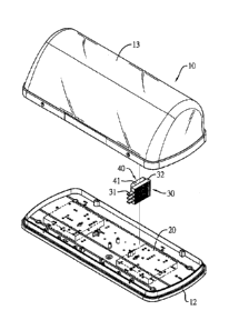
With reference to Figs. 1 to 3, a warning light in accordance with the
16 present invention comprises a shell 10, a light-emitting device 20, a
heating
17 device 30, and an assisted diversion member 40.
18 With reference to Figs. 4 and 5, the shell 10 has a chamber 11 formed
19 in the shell 10. The shell 10 has a seat 12 and a cover 13. The cover 13
is
mounted on the seat 12. The chamber 11 is formed between the seat 12 and the
21 cover 13.
22 With reference to Fig. 5, the light-emitting device 20 is mounted in the
23 shell 10 and is located in the chamber 11 of the shell 10. The light-
emitting
24 device 20 is mounted on an inner surface of the seat 12 of the shell 10.
A light
Date Recue/Date Received 2020-11-05
5
1 exit end of the light-emitting device 20 faces the cover 13. Light
emitted by the
2 light-emitting device 20 can pass through the light exit end of the light-
emitting
3 device 20 and the cover 13.
4 With reference to Fig. 5, the heating device 30 is mounted in the shell
10 and is located in the chamber 11 of the shell 10. The heating device 30 can
6 generate heat energy to air in the chamber 11 of the shell 10. The
heating
7 device 30 has at least one heating element 31. Each one of the at least
one
8 heating element 31 has a heat sink module 32. The heat sink module 32 is
9 mounted on the seat 12.
With reference to Fig. 5, the assisted diversion member 40 is mounted
11 into the chamber 11 of the shell 10 and is located beside the heating
device 30
12 to assist the air in the chamber 11 of the shell 10 to flow. The
assisted diversion
13 member 40 has at least one fan 41 mounted beside the heat sink module
32.
14 According to demands, a number of the at least one heating element 31
and a number of the at least one fan 41 can be adjusted. An installation
position
16 of each one of the at least one heating element 31 and an installation
position of
17 each one of the at least one fan 41 can be adjusted according to a
position of the
18 light-emitting device 20.
19 With reference to Fig. 6, in a snowy environment, the at least one
heating element 31 of the heating device 30 works to supply the heat energy.
21 The heat energy is transmitted to the said heat sink module 32. The
heating
22 device 30 can co-work with the assisted diversion member 40. The air in
the
23 chamber 11 of the shell 10 is driven by the assisted diversion member 40
and
24 flows through the said heat sink module 32. The flowing air absorbs the
heat
Date Recue/Date Received 2020-11-05
6
1 energy transmitted to the said heat sink module 32 to form the hot air
flow. The
2 hot air flow flows quickly and completely, and contacts the cover 13 of
the
3 shell 10 evenly. The heat energy can be transmitted to the cover 13 of
the shell
4 10 evenly.
In the warning light, the heating device 30 co-works with the assisted
6 diversion member 40 to form the hot air flow flowing in the chamber 11 of
the
7 shell 10. The heat energy is evenly transmitted to the cover 13 of the
shell 10
8 by the flowing hot airflow. Snow falls on the cover 13, absorbs the heat
energy
9 transmitted to the cover 13, and then is melted and is removed from the
cover
13 for preventing the snow from obstructing the light passing through the
cover
11 13. The light emitted by the light-emitting device 20 can pass through
the
12 cover 13 smoothly without being affected by snow. Luminous performance
of
13 the warning light is improved.
14
Date Recue/Date Received 2020-11-05