Note: Descriptions are shown in the official language in which they were submitted.
CA 03098284 2020-10-23
WO 2019/209157 PCT/SE2019/050349
1
Plow steel for a snow plow, and methods for manufacturing and using such a
plow steel
The present invention relates to a plow steel for a snow plow. In particular,
the present
invention relates to a detachable and replaceable plow steel of the said type
comprising a
wear part. The present invention also relates to a method for manufacturing
such a plow
steel, and to the use of such a plow steel.
Motor-driven snow plows are conventionally used for clearing paved streets and
other hard
surfaces from snow and ice. By scraping a plow blade across the surface, snow
and ice is
w removed from the surface and can be pushed to the side of a road;
collected for evacuation;
or handled in any other desired way.
A plow blade is used as the point of contact with the hard surface across
which it is scraped
and is therefore subjected to extensive wear during use. The hard surface may
be made
from asphalt, concrete, gravel and so forth, and may have sand or other
granular abrasive
and/or friction-increasing material already on it at the time of snow plowing.
Many times, a layer of ice and/or compacted snow is present on the hard
surface, which
the plow blade needs to be able to penetrate and remove. Often, it is desired
to plow a
surface, such as a road, at relatively high velocities, while still being able
to remove snow
and ice sufficiently so as not having to pass several times.
To sum up, in order to perform adequately, the plow blade needs to be able to
withstand
heavy wear for prolonged periods of time. Plow blades need replacement after
certain use,
which is not only expensive in terms of replacement blades, but also poses
logistic and plan-
ning challenges.
In order to handle uneven surfaces, it has been proposed to construct plow
blades with
rubber wear surfaces, offering a certain flexibility in the contact with the
hard surface. The
present invention, in contrast thereto, relates to plow blades featuring at
least partly a
CA 03098284 2020-10-23
WO 2019/209157 PCT/SE2019/050349
2
metal wear surface. Such plow blades are herein denoted "plow steels". Such a
plow steel
may also be used as a detachable and replaceable wear part on a larger plow
blade.
For such plow steels, it is known to use a toothed metal contact surface,
arranged to contact
the hard surface. The teeth maximize the contact pressure while snow plowing.
It is also known to use tungsten carbide inserts in a plow steel to increase
its abrasive re-
sistance and prolong its useful life. For instance, 5E9804018-1 discloses the
use of soldered-
in cemented carbide inserts in a steel blade.
In 5E0500764-5, a plow blade is disclosed featuring a corrugated surface.
There are a number of problems with conventional steel blades, in addition to
the ones
pointed out above.
Firstly, it is desirable to scrape off as much snow and ice as possible, not
leaving substantial
amounts of snow or ice on the road as snowbanks or snowdrifts. For instance,
snow or ice
may be left behind if the plow blade has substantial space between hard
surface contacting
points.
Secondly, it is desired to leave a certain amount of friction-increasing sand,
or other granu-
lar mineral material, which may be already present on the surface or be
applied during snow
plowing, on the hard surface even after the plow steel has passed a particular
part of the
snow plowed surface.
This should be achieved in an uncomplicated and easily reproducible way, with
a plow steel
with good durability and which is not more expensive than necessary.
The present invention solves the above described problems.
CA 03098284 2020-10-23
WO 2019/209157 PCT/SE2019/050349
3
Hence, the invention relates to a plow steel for a snow plow, comprising: a
fastening means
for fastening the plow steel to a snow plow; a main steel support plate, with
a main plane
extending across a width and a height dimension; and a surface contacting
edge, running in
the width dimension along said steel support plate, which surface contacting
edge com-
prises a set of indentations formed in the height dimension in the metal
support plate,
hence forming a set of surface contacting teeth along the surface contacting
edge and ar-
ranged between said indentations along the width dimension, which plow steel
is charac-
terised in that each of said teeth comprises an insert made of a wear-
resistant material with
better abrasive resistance than the steel material of said steel support
plate, which inserts
ho do not cover said indentations in a depth dimension perpendicular to
said main plane, and
in that the steel support plate comprises an elongated steel flange covering
said indenta-
tions in the depth dimension.
Moreover, the invention relates to a method for manufacturing a plow steel of
the said
type, which manufacturing method is characterised in that it comprises the
following steps:
a) providing a main steel support plate, with a main plane extending across a
width and a
height dimension, and comprising a surface contacting edge running in the
width dimension
along said steel support plate, which surface contacting edge comprises a set
of indenta-
tions formed in the height dimension in the metal support plate hence forming
a set of
surface contacting teeth between said indentations along the width dimension,
as well as
an elongated steel flange covering said indentations in the depth dimension;
b) providing a
set of inserts made of a wear-resistant material with better abrasive
resistance than the
steel material of said steel support plate; and c) permanently fastening a
respective of said
inserts at each of said teeth, in a way so that the fastened inserts do not
cover said inden-
tations in the depth dimension.
Furthermore, the invention relates to a method for using a plow steel of the
said type, for
snow plowing a hard surface, which use method is characterised in that it
comprises the
following steps: a) mounting a plow steel of said type to a motorized snow
plow, using fas-
tening means of said plow steel; b) snow plowing said hard surface until the
steel material
of the steel flange has worn down partly into said indentations from the
surface contacting
CA 03098284 2020-10-23
WO 2019/209157 PCT/SE2019/050349
4
edge in the height dimension; c) continuing to snow plow said hard surface,
allowing the
inserts to wear down; d) replacing the plow steel for a new plow steel of the
said type; and
e) reiterating from step b.
In the following, the invention will be described in detail, with reference to
exemplifying
embodiments of the invention and to the enclosed drawings, wherein:
Figure 1 is a perspective view of a prior art plow steel;
Figure 2 is a perspective view of a plow steel according to the present
invention;
w Figure 3 is a cross-sectional perspective view of the plow steel
illustrated in Figure 1;
Figure 4 is a first plan view of a plow steel according to the present
invention;
Figure 5 is a second plan view of the plow steel shown in Figure 4;
Figure 6 is a detail view of Figure 5, according to marking "B" in Figure 5;
Figure 7 is a flow chart illustrating a method according to the present
invention for manu-
is .. facturing a plow steel; and
Figure 8 is a flow chart illustrating a method according to the invention for
using a plow
steel.
The Figures share the same reference numerals for the same or corresponding
parts.
Figure 1 illustrates a prior art plow steel 1, comprising three fastening
means 10 for fas-
tening the plow steel 1 to a snow plow (not shown). The plow steel 1 also
comprises a main
steel support plate 20, extending in a main plane across a width W and a
height H dimen-
sion. A depth dimension D extends perpendicularly to said support plane 20.
The support
plane 20 in essence is constructed as a relatively thick piece of sheet steel
metal.
The plow steel 1 further comprises a surface contacting edge 30, in fact
forming a lower
edge of the support plate 20 in an orientation of the plow steel 1 used during
snow plowing
operation. Thus, the surface contacting edge 30 is arranged to contact a
ground surface
during such snow plowing use.
CA 03098284 2020-10-23
WO 2019/209157 PCT/SE2019/050349
As illustrated in Figure 1, the surface contacting edge 30 is split up into
two elongated edges
or flanges, having an elongated recess 60 therebetween. In and along the
recess 60, an in-
sert 40 made from cemented carbide is arranged.
5 During use, the insert 40 will prevent the plow steel 1 from being worn
down too quickly.
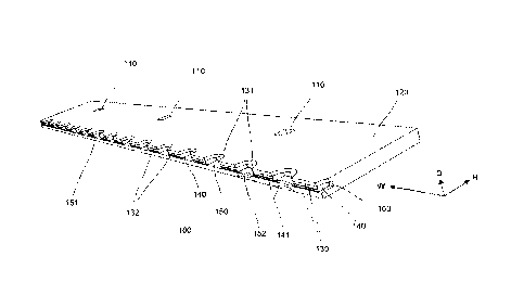
In contrast to the plow steel illustrated in Figure 1, Figures 2-6 illustrate
a plow steel 100
according to the present invention. As is the case for the plow steel 1, the
inventive plow
steel 100 also comprises a fastening means 110 for fastening the plow steel
100 to a snow
w plow (not shown). The fastening means 110 may be in the form of a series
of through holes,
as is illustrated in the Figures, but may also have other suitable geometric
configurations.
Similarly, to the plow steel 1 illustrated in Figure 1, the plow steel 100
comprises a main
steel support plate 120, with a main plane extending across a width W and a
height H di-
is mension. A depth D dimension extends perpendicularly to the said main
plane.
Furthermore, the plow steel 100 comprises a surface contacting edge 130,
running in the
width W dimension along said steel support plate 120. The surface contacting
edge 130
comprises a set of indentations 131, formed in the height H dimension in the
metal support
20 plate 120, hence forming a set of surface contacting teeth 132 along the
surface contacting
edge 130 and arranged between said indentations 131 along the width W
dimension of the
support plate 120.
Hence, the surface contacting edge 130 is an at least partly toothed edge,
such that the
25 teeth 132 contact the surface during snow plowing operation of the plow
steel 100.
According to the present invention, each of said teeth 132 comprises an insert
140, prefer-
ably individual inserts 140 as will be described below, made of a wear-
resistant material
with better abrasive resistance than the steel material of said steel support
plate 120. As is
30 illustrated in Figure 1, these inserts 140 do not cover said
indentations 131 in the depth D
dimension.
CA 03098284 2020-10-23
WO 2019/209157 PCT/SE2019/050349
6
Further according to the invention, the steel support plate 120 comprises an
elongated steel
flange 150 covering said indentations 132 in the depth D dimension.
As is realized, the plow steel is used, for snow plowing, with the surface
contacting edge
130 facing downwards and the main plane perpendicularly or substantially
perpendicularly
oriented. In this use snow plowing operation orientation, when the plow steel
100 is at-
tached to a snow plow in the form of a tractor, a truck, a car or similar, the
plow steel 100
scrapes along the plowed surface, bringing with it snow, ice, granular
material and so forth.
Such a plow steel 100 offers excellent ground surface contact during such use,
due to the
toothed surface contacting edge. It also provides good abrasive wear
resistance, due to the
inserts 140, and as a result a long useful life.
Finally, the relatively soft material of the flange 150 between the inserts
140 will wear down
considerably faster than the inserts 140, leaving a worn-down, indented part
152 (illus-
trated for two pairs of inserts 140 in phantom lines in Figure 2) of the
flange 150 between
each pair of inserts 140. The such formed indented part 152 hence forms a
secondary
toothed pattern extending across the surface contacting edge 130, further
improving sur-
face contact and providing improved snow plowing action.
Namely, since the indentations 152 hence formed automatically align with the
indentations
131, the surface contact edge 130 as a whole is provided with a toothed
overall shape during
use. This wear-down of the flange 150 forming the indentations 152 can be
achieved rela-
tively quickly, such as after only a few tens of kilometres of snow plowing
action on a normal
tarmac road, for instance.
It has also turned out that, for surfaces comprising both snow or ice material
and granular
mineral material, such as sand, mixed in the snow or ice on the surface, the
toothed overall
shape mentioned above will be sufficiently varying (in the height H dimension)
so as to allow
certain granular material to stay on the surface even after plowing. At the
same time, the
CA 03098284 2020-10-23
WO 2019/209157 PCT/SE2019/050349
7
wear of the metal material will in general not be too large so as to create
large formations
of granular material on the plowed surface. Rather, such granular material
will in general
be present in the valleys produced by the teeth 132 (with the inserts 140),
from where it is
not easily dispersed by the wind created by vehicles travelling along the
surface.
Figure 3 illustrates the plow steel 100 in a cross-sectional view, in which
part of the plow
steel 100 arranged on one side of a certain cross-sectional plane, extending
in the width W
and height H directions, has been removed. Figure 3 illustrates this cross-
sectional plane.
As is illustrated in Figure 3, and according to a preferred embodiment of the
present inven-
w tion, the individual inserts 140 are separated from each other at each
indentation 131, along
the width W dimension.
Regarding the steel flange 150, it is preferred that this covers not only the
indentations 131
(as described above), but also that it covers the teeth 132, as seen in the
depth D dimension.
This is preferably true for at least most, preferably substantially all, most
preferably all of
said teeth 132.
Furthermore, it is preferred that the steel flange 150 comprises an elongated
edge 151 run-
ning along the said contacting edge 130, such as in parallel to the contacting
edge 130 along
the whole length, or at least substantially the whole length, of the
contacting edge 130.
Preferably, the edge 151 forms part of the surface contacting edge 130.
As is illustrated in Figures 2-6, at least half of the individual ones of said
inserts 140, prefer-
ably substantially all of said individual inserts 140, preferably all of the
individual inserts
140, are arranged, in the dept D dimension, between the tooth 132
corresponding to (ar-
ranged adjacent to in the depth D dimension) the insert 140 in question and
the steel flange
150. Preferably, in each case the insert 140 in question has a shape, in the
main plane, which
roughly corresponds to the shape of the corresponding tooth 132. Preferably,
in the main
plane, the insert 140 in question may cover at least 75% of the surface
covered by the tooth
132 in question. In some embodiments, the insert 140 does not extend outside
of the cor-
responding tooth 132 in the main plane.
CA 03098284 2020-10-23
WO 2019/209157 PCT/SE2019/050349
8
According to one exemplifying embodiment, all of said inserts 140, or at least
substantially
all of said inserts 140, are soldered to the metal support plate 120.
As is illustrated in Figures 2-6, the support plate 120, the teeth 132 and the
steel flange 150
may together form one single, connected body of steel. Suitable steel
materials include
5355J2+N and hardened steels.
In particular, the said body of steel may comprise the elongated recess 160
extending from
ho the surface contacting edge 130 and inwards, in the height H dimension,
which elongated
recession 160 accommodates the inserts 140. As is illustrated in Figures 2-6,
each insert 140
arranged in the recess 160 may, this way, be enclosed on either side by the
flange 150 and
the tooth 132, respectively.
In particular, the elongated recess 160 may have a thickness, in the depth D
dimension,
which is substantially equal along the surface contacting edge 130.
The wear-resistant material of the inserts 140 may be tungsten carbide. It may
also be other
materials that are considerably harder than the steel type used in the steel
plate 120, such
as chrome carbide. Preferably, the abrasive resistance of the material of the
inserts 140 is
at least 3, preferably at least 5 times larger, as measured in HBW, than that
of the metal
steel plate 120 material.
Regarding the inserts 140 in general, at least some of the inserts 140,
preferably substan-
tially all inserts 140, more preferably all of the inserts 140, may comprise a
cutting edge 141
facing, along the height H dimension, in the same direction as the surface
contacting edge
130, preferably forming part of the surface contacting edge 130.
As is further illustrated in Figures 2-6, the teeth 132, the steel flange 150
and the inserts
140 may all extend substantially equally far in the height H dimension towards
the surface
contacting edge 130, and hence together forming the surface contacting edge
130. In other
CA 03098284 2020-10-23
WO 2019/209157 PCT/SE2019/050349
9
words, during snow plowing use, the teeth 132, the steel flange 150 and the
inserts 140 in
this case all constitute part of the surface contacting edge 130 and contact
the surface di-
rectly during snow plowing use.
Preferably, most, preferably substantially all, more preferably all, of said
indentations 131
are at least 2 cm wide, preferably at least 3 cm wide, in the width W
dimension. Correspond-
ingly, most, preferably substantially all, preferably all, of said
indentations 131 may be at
the most 10 cm wide, preferably at the most 5 cm wide, in the width W
dimension.
ho Preferably, most, preferably substantially all, more preferably all, of
said indentations 131
are at least 1 cm high in the height H dimension, as measured from the surface
contacting
edge 130. Correspondingly, most, preferably substantially all, preferably all,
of said inden-
tations 131 may be at the most 3 cm high, preferably at the most 2 cm high, in
the height H
dimension, as measured from the surface contacting edge 130.
The corresponding measurements apply to the inserts 140, even if it is
realized that the size
in the main plane of the inserts 140 is not directly related to the size of
the adjacently ar-
ranged indentations 131. Hence, each individual tooth 132 and each individual
insert 140
may preferably be between 2 and 10 cm wide in the width W dimension and
between 1 and
3 cm in the height H dimension. The elongated recess 160 may have the same
height H
dimension extension as the inserts 140, so that the inserts 140 are arranged
to abut the
bottom of the recess 160 in the height H dimension.
The metal plate 120 is preferably between 0,5 and 10 cm thick, preferably
between 0.8 and
.. 5 cm thick in the depth D dimension. The inserts 140 are each preferably
between 25-60%
of the total metal plate 120 thickness in the depth D dimension. Preferably,
the whole plow
steel 100 may form a plate structure which has a substantially or completely
uniform thick-
ness (in the depth D dimension) across its entire main plane extension.
The plow steel 100 is preferably at least 50 cm wide in the width W dimension,
preferably
at least 60 cm wide. It is furthermore preferably at the most 200 cm wide,
preferably at the
CA 03098284 2020-10-23
WO 2019/209157 PCT/SE2019/050349
most 180 cm wide. It is furthermore preferably at least 10 cm high in the
height H dimension
and is preferably at the most 50 cm high. It is preferably of substantially
planar constitution.
Figure 7 illustrates a method according to the invention, for manufacturing a
plow steel 100
5 of the type described above and herein.
In a first step, the method starts.
In a subsequent step, a main steel support plate 120 is provided of the type
described
ho above, with said main plane extending across the width W and height H
dimensions and
comprising the said surface contacting edge 130 running in the width W
dimension along
the steel support plate 120 in question. As described above, the surface
contacting edge
130 comprises a set of indentations 131 formed in the height H dimension in
the metal
support plate 120, hence forming said set of surface contacting teeth 132
between said
indentations 131 along the width W dimension, as well as an elongated steel
flange 150
covering the indentations 131 in the depth D dimension.
The steel support plate 120 can in turn be manufactured using a more detailed
manufac-
turing protocol, comprising machining steps providing said recess 160 and so
forth.
In a subsequent step, a set of inserts 140 are provided, made of a wear-
resistant material
of the above described type, having better abrasive resistance than the steel
material of
said steel support plate 120.
In a subsequent step, a respective one of said inserts 140 is permanently
fastened to each
of said teeth 132, respectively, in a way so that the fastened inserts 140 do
not cover said
indentations 131 in the depth D dimension. For instance, the inserts 140 may
be soldered
to the steel material as described above.
Then, the method ends.
CA 03098284 2020-10-23
WO 2019/209157 PCT/SE2019/050349
11
Figure 8 illustrates a method according to the present invention for using a
plow steel 100
of the type described above and herein, for snow plowing a hard surface. The
hard surface
may preferably be a paved surface, such as a tarmac surface. It may
alternatively be a con-
crete or gravel surface. Preferably, the surface is a road surface, an airport
surface or a
parking surface. Herein, the term "snow plowing" is intended to cover the
mechanical re-
moval of snow, ice and any unwanted granular material from such a surface,
using a scrap-
ing action using the said plow steel 100 mounted on a motorized snow plow.
In a first step, the method starts.
In a subsequent step, a plow steel 100 of said type is mounted to a motorized
snow plow,
using the fastening means 110 of the plow steel 100.
In a subsequent step, the said hard surface is snow plowed until the steel
material of the
elongated edge 151 of the steel flange 150 has worn (inwards) down partly into
said inden-
tations 131 from the surface contacting edge 130 in the height H dimension.
Preferably, this
step lasts until the elongated edge 151 has worn down at least 0.5 cm from the
surface
contacting edge 130 and may be performed at a different intensity or velocity
than the sub-
sequent snow plowing step. In most cases, from a few kilometres up to a few
tens of kilo-
metres is enough to achieve such wear of the elongated edge 151.
After this step, which may be seen as a first snow plowing phase using the
plow steel 100,
the whole surface contacting edge 130 displays a toothed or wave-shaped
contour, as has
been described above.
In a subsequent step, which may be seen as a second snow plowing phase using
the plow
steel 100, snow plowing of the said hard surface is continued, allowing the
inserts 140 to
wear down to such an extend so that snow plowing becomes so inefficient so
that replace-
ment of the plow steel 100 is called for. During this step, as the inserts 140
wear down
inwards in the height H dimension, it is realized that the now generally wave-
shaped elon-
gated edge 151 also continues to wear inwards, maintaining the wave-shaped
overall
CA 03098284 2020-10-23
WO 2019/209157 PCT/SE2019/050349
12
contour of the surface contacting edge 130 throughout the whole useful life of
the plow
steel 100. During this second phase, a wave pattern is typically produced in
the snow or ice
material present on the plowed surface and yielding the above discussed result
with any
intermixed granular material present in the valleys created.
In a subsequent step, the plow steel 100 is replaced for a new plow steel 100
of the same
type. Hence, the used plow steel 100 is demounted from the snow plow, and the
replace-
ment plow steel 100 is mounted to the snow plow.
ho In a subsequent step, the method reiterates from the step in which the
elongated edge 151
was initially worn down to create said wave-shaped contour of the surface
contacting edge
130.
In a subsequent step, the method ends.
The present invention, in addition to the advantages described above, offers a
plow steel
100 which combines the durability resulting from the use of the high abrasive
resistance
material (of the inserts 140) along the surface contacting edge 130, without
requiring a very
thick steel material. This provides a durable yet affordable plow steel.
In the above described first phase, before the steel flange 150 has been worn
down to form
said waved contour shape, the plow steel 100 will still allow efficient
plowing of snowy
roads, in particular of roads with plenty of packed snow but without any
larger amounts of
abrasive sand intermixed with the packed snow. Hence, for such roads the plow
steel 100
can be used efficiently even before the plow steel 100 has been used on more
abrasive
surfaces so that the steel flange 150 forms said waved contour shape. It is
even the case
that this abrasive wear of the steel flange 150 does not occur at all, or only
occurs to a
limited extent, in the absence of abrasive granular material on the plowed
surface. Hence,
the plow steel 100 may be used for efficient snow plowing during extended time
periods in
the first phase on such surfaces. This is particularly the case under
conditions with large
amounts of snow, and in particular freshly fallen snow. The same snow plow 100
may then
CA 03098284 2020-10-23
WO 2019/209157 PCT/SE2019/050349
13
be converted for second phase operation by simply starting using under more
abrasive con-
ditions, allowing the steel flange 150 to wear down as described above.
This further adds to the flexibility of use of the present plow steel 100.
It is furthermore so that the first phase operation provides specifically
efficient snow plow-
ing under non-abrasive conditions; while the second phase operation provides
specifically
efficient snow plowing under more abrasive conditions. The latter is
particularly true for
sanded roads with ice buildup, for removing such ice while not removing all
sand but instead
giving rise to a wave pattern in the ice that actually achieves sand
retaining.
Hence, the present invention offers a plow steel 100 which can be used under
diverse op-
erating conditions, while still offering long useful life to a reasonable
cost.
Above, preferred embodiments have been described. However, it is apparent to
the skilled
person that many modifications can be made to the disclosed embodiments
without de-
parting from the basic idea of the invention.
For instance, it is realized that the plow steel 100 and the methods described
above may
have additional features, as long as the principles described herein are
observed.
In particular, the teeth 132 and the inserts 140 may be differently shaped
than what is illus-
trated in the Figures, and the metal steel plate 120 may have additional
features and shapes.
In general, all which has been said regarding the plow steel 100 is equally
applicable to the
manufacturing method. The corresponding is true also between the plow steel 10
the use
method; as well as between the manufacturing method and the use method.
Hence, the invention is not limited to the described embodiments, but can be
varied within
the scope of the enclosed claims.