Note: Descriptions are shown in the official language in which they were submitted.
CA 03098658 2020-10-28
WO 2019/212940
PCT/US2019/029588
OPHTHALMIC SURGICAL INSTRUMENTS AND METHODS OF USE THEREOF
BACKGROUND
Technical Field
[0001] The
present disclosure relates to ophthalmic surgical instruments, and more
particularly, to ophthalmic surgical instruments and methods that facilitate
the fragmentation
and removal of a lens from a lens capsule.
Background of Related Art
[0002]
Cataract surgery and other surgical procedures that treat lenticular tissue,
such
as, for example, the intraocular lens, are performed by making a small
incision in the edge of
the cornea, which provides access to the anterior chamber and to the anterior
surface of the lens
capsule. Afterward, a generally circular incision called a capsulorhexis is
made through the
anterior surface of the lens capsule to provide surgical access to the lens.
An ophthalmic
surgical instrument may be inserted through the capsulorhexis and used to
fragment the
cataractous lens to facilitate its removal from the lens capsule. However,
during segmentation
by the surgical instrument, the distal portion of the lens may be caused to
shift undesirably in
an upward (i.e., anterior) direction. Such movement may cause trauma to
delicate adjacent eye
structures such as the lens zonule, lens capsule or, corneal endothelium.
[0003]
Accordingly, a continuing need exists in the surgical arts for improved tools
and
methods for safely fragmenting and removing a cataractous lens.
SUMMARY
[0004] In
accordance with an aspect of the present disclosure, an ophthalmic surgical
instrument is provided and includes a housing and a snare operably coupled to
the housing.
1
CA 03098658 2020-10-28
WO 2019/212940
PCT/US2019/029588
The housing has a handle body and a hollow shaft extending distally of the
handle body. The
snare includes a looped segment configured to move between a contracted
configuration and a
dilated configuration. In the dilated configuration, the looped segment
assumes a diameter and
shape approximating a diameter and shape of a cataractous lens. The looped
segment is
configured to sever the cataractous lens upon moving toward the contracted
configuration. A
majority of the looped segment overlaps with a lateral side of the hollow
shaft when the looped
segment is in the dilated configuration.
[0005] In
aspects, a majority of the looped segment may be disposed proximally of a
distal end of the hollow shaft.
[0006] In
aspects, the hollow shaft may define a lateral opening in the lateral side
thereof. The looped segment may protrude from the lateral opening.
[0007] In
aspects, the looped segment may include a proximal section disposed
proximally of the lateral opening, and a distal section disposed distally of
the lateral opening.
[0008] In
aspects, both the proximal and distal sections of the looped segment may be
disposed proximally of a distal end of the hollow shaft when the looped
segment is in the
contracted configuration.
[0009] In
aspects, a majority of the distal section of the looped segment may be
disposed proximally of a distal end of the hollow shaft when the looped
segment is in the
contracted configuration.
[0010] In
aspects, the majority of the looped segment may overlap with the lateral side
of the hollow shaft throughout the transition of the looped segment between
the contracted and
dilated configurations.
2
CA 03098658 2020-10-28
WO 2019/212940
PCT/US2019/029588
[00111 In
aspects, the looped segment may define a length that is parallel with a
central
longitudinal axis defined by the hollow shaft. A majority of the length of the
looped segment
may be in side-by-side relation with the lateral side of the hollow shaft.
[0012] In
aspects, the snare may be a wire having a first end portion configured to be
coupled to a lever of the housing, and a second end portion fixed relative to
the housing. The
looped segment may be formed between the first and second end portions of the
wire.
[0013] In
another aspect of the present disclosure, an ophthalmic surgical instrument
for severing a cataractous lens is provided and includes a
housing, a snare operably
coupled to the housing, and a pair of opposing arms operably coupled to the
housing. The
snare includes a looped segment configured to move between a contracted
configuration and a
dilated configuration, in which the looped segment assumes a diameter
approximating a
diameter of a cataractous lens. The looped segment is configured to sever the
cataractous lens
upon moving toward the contracted configuration. The pair of arms are disposed
on opposite
sides of the looped segment of the snare. The pair of arms are configured to
move between a
collapsed configuration and an expanded configuration, in which the pair of
arms extend
outwardly relative to the looped segment of the snare.
[0014] In
aspects, the looped segment of the snare may define a first plane, and the
pair
of arms together may define a second plane that is perpendicular to the first
plane.
[0015] In
aspects, the pair of arms may be disposed in the second plane in both the
collapsed and expanded configurations.
[0016] In
aspects, the pair of arms may define an acute angle therebetween when in the
expanded configuration.
3
CA 03098658 2020-10-28
WO 2019/212940
PCT/US2019/029588
[0017] In
aspects, the pair of arms may be configured to pivot outwardly away from
one another and a longitudinal axis defined by the snare when moving toward
the expanded
configuration.
[0018] In
aspects, the pair of arms may be axially movable relative to the housing
between a proximal position, in which the pair of arms are disposed within the
housing, and a
distal position, in which the pair of arms are disposed outside of the
housing.
[0019] In
aspects, the pair of arms may be configured to automatically move toward
the expanded configuration upon advancing toward the distal position.
[0020] In
aspects, each of the pair of arms may have a posterior surface that defines an
arcuate recess dimensioned to conform to an anterior surface of a human lens.
[0021] In
aspects, the pair of arms may be resiliently biased toward the expanded
configuration.
[0022] In
aspects, the housing may include a first lever operably coupled to the snare,
and a second lever operably coupled to the pair of arms. Movement of the first
lever may move
the looped segment between the contracted and dilated configurations, whereas
movement of
the second lever may move the pair of arms between the collapsed and expanded
configurations.
[0023] In
aspects, the snare may be a wire having a first end portion coupled to the
first
lever, and a second end portion fixed relative to the housing.
[0024]
Further details and aspects of exemplary embodiments of the present disclosure
are described in more detail below with reference to the appended figures.
4
CA 03098658 2020-10-28
WO 2019/212940
PCT/US2019/029588
[0025] As
used herein, the terms parallel and perpendicular are understood to include
relative configurations that are substantially parallel and substantially
perpendicular up to about
+ or ¨ 10 degrees from true parallel and true perpendicular.
BRIEF DESCRIPTION OF THE DRAWINGS
[0026]
Embodiments of the present disclosure are described herein with reference to
the accompanying drawings, wherein:
[0027] FIG.
1A is a top view of an ophthalmic surgical instrument in accordance with
an embodiment of the present disclosure, illustrating a snare thereof in a
contracted
configuration;
[0028] FIG.
1B is a top view of the ophthalmic surgical instrument of FIG. 1A,
illustrating the snare in a dilated configuration and a pair of stabilization
elements in an open
configuration;
[0029] FIG.
2A is a side cross-sectional view of the ophthalmic surgical instrument of
FIG. 1A, illustrating the snare in the contracted configuration and the
stabilization elements in
the closed configuration;
[0030] FIG.
2B is a side cross-sectional view of the ophthalmic surgical instrument of
FIG. 1A, illustrating the snare in the dilated configuration and the
stabilization elements in the
open configuration;
[0031] FIG.
3A is a top cross-sectional view of the ophthalmic surgical instrument of
FIG. 1A, illustrating the snare in the contracted configuration and the
stabilization elements in
the closed configuration;
CA 03098658 2020-10-28
WO 2019/212940
PCT/US2019/029588
[0032] FIG.
3B is a top cross-sectional view of the ophthalmic surgical instrument of
FIG. 1A, illustrating the snare in the dilated configuration and the
stabilization elements in the
open configuration;
[0033] FIG.
4A is a side view of another embodiment of an ophthalmic surgical
instrument, illustrating a snare thereof in a contracted configuration;
[0034] FIG.
4B is a side view of the ophthalmic surgical instrument of FIG. 4A,
illustrating the snare in a dilated configuration;
[0035] FIG.
5A is a side view of yet another embodiment of an ophthalmic surgical
instrument, illustrating a snare thereof in a contracted configuration; and
[0036] FIG.
5B is a side view of the ophthalmic surgical instrument of FIG. 5A,
illustrating the snare in a dilated configuration.
DETAILED DESCRIPTION
[0037]
Embodiments of the presently disclosed ophthalmic surgical instruments are
described in detail with reference to the drawings, in which like reference
numerals designate
identical or corresponding elements in each of the several views. As used
herein and as is
traditional, the term "distal" will refer to that portion of the ophthalmic
surgical instrument
which is further from the user (i.e., closer to the eye) while the term
"proximal" will refer to
that portion of the ophthalmic surgical instrument which is closer to the user
(i.e., further from
the eye).
[0038] The
present disclosure provides embodiments of an ophthalmic surgical
instrument used to fragment cataractous lenticular tissue prior to its removal
from a lens
capsule. The ophthalmic surgical instrument includes a handle portion, a snare
for enclosing
6
CA 03098658 2020-10-28
WO 2019/212940
PCT/US2019/029588
and severing the lenticular tissue, and a pair of stabilization elements that
are selectively
extendable outwardly relative to the snare during actuation of the snare. The
stabilization
elements may be any suitable structure that extends outwardly from the distal
end or from
opposite sides of the snare to overlay opposing sides of the lenticular tissue
during its division
by the snare. As the snare is contracted about the lenticular tissue, the
stabilization elements
resist anterior shifting (i.e., upward shifting) of the lenticular tissue,
which may otherwise occur
due to the proximally-oriented force exerted on the lenticular tissue during
contraction of the
snare. In some embodiments, the ophthalmic surgical instrument is constructed
so that a
distally-extending cannula thereof acts as the stabilization element. These
and other features
and advantages of the various embodiments of the disclosed ophthalmic surgical
instruments
will be described below.
[0039] With
reference to FIGS. 1A-3C, an exemplary embodiment of an ophthalmic
surgical instrument is illustrated and is generally designated 100. The
ophthalmic surgical
instrument 100 generally includes a housing 110, a snare 112 for severing
lenticular tissue, and
a pair of stabilization elements, such as, for example, elongated arms 120,
122 that selectively
expand from a closed or collapsed configuration (FIGS. 1A, 2A, 3A) to an open
or expanded
configuration (FIGS. 1B, 2B, 3B).
[0040] The
housing 110 of the ophthalmic surgical instrument 100 has a handle body
114 and first and second levers 116a, 116b slidably coupled to the handle body
114. The handle
body 114 may be ergonomic and have an elongated configuration. In embodiments,
the handle
body 114 may assume any suitable shape, such as, for example, rounded, planar,
rectangular,
or the like. The handle body 114 has a tapered distal end portion 118
dimensioned to assist in
positioning the ophthalmic surgical instrument 100 adjacent eye structure. The
levers 116a,
116b may be configured as sliders, buttons, triggers, or the like. In
embodiments, the housing
7
CA 03098658 2020-10-28
WO 2019/212940
PCT/US2019/029588
110 may include a cannulated member, such as, for example, a hollow shaft (not
shown),
extending distally from the distal end portion 118 of the handle body 114 to
facilitate entry of
the ophthalmic surgical instrument 100 through a standard corneal incision.
[0041] The
snare 112 of the ophthalmic surgical instrument 100 is operably coupled to
the first lever 116a of the housing 110 and includes a first end portion 112a
and a second
end portion 112b (FIGS. 2A and 2B). The first end portion 112a of the snare
112 is movable
relative to the housing 110, while the second end portion 112b of the snare
112 is fixed relative
to the housing 110. In particular, the first end portion 112a of the snare 112
is coupled to the
first lever 116a of the housing via a first actuator rod 124, such that
movement of the first lever
116a moves the first end portion 112a of the snare 112, and the second end
portion 112b of the
snare 112 is fixed to an inner tubular structure 126 (FIGS. 3A and 3B) formed
in the distal end
portion 118 of the handle body 114. It is contemplated that the second end
portion 112b of the
snare 112 may be fixed to the inner tubular structure 126 of the handle body
114 by crimping,
welding, adhesives, mechanical interlocks, or any other suitable structure or
method.
[0042] With
reference to FIGS. 2A and 2B, the snare 112 has a looped segment 128
disposed at least partially outside of the housing 110. The looped segment 128
of the snare
112 is transitionable, via an actuation of the first lever 116a, between an
insertion or contracted
configuration, as shown in FIGS, 1A, 2A, and 3A, and a deployed or dilated
configuration, as
shown in FIGS. 1B, 2B, and 3B. For example, a proximal retraction of the first
lever 116a
moves the first end portion 112a of the snare 112 proximally away from the
second end portion
112b of the snare 112, thereby reducing the diameter of the looped segment
128. In contrast,
a distal advancement of the first lever 116a moves the first end portion 112a
of the snare 112
distally toward the second end portion 112b of the snare 112, thereby
increasing the diameter
of the looped segment 128 of the snare 112. The looped segment 128 has a
predefined shape
8
dimensioned to closely encircle a lens when the looped segment 128 is in the
dilated
configuration.
[0043] In embodiments, at least the looped segment 128 of the snare 112
may be a
metal or polymer wire, tether, strap, belt, or the like, with any suitable
cross-section
configuration configured to sever lenticular tissue during contraction of the
looped segment
128 about the lenticular tissue.
[0044] For an exemplary description of further features of the snare
112 and the
mechanism of its operation, reference may be made to U.S. Patent No.
9,775,743, filed on
September 17, 2014.
[0045] With continued reference to FIGS. 1B and 2A-3B, the
stabilization elements or
arms 120, 122 of the ophthalmic surgical instrument 100 are disposed on
opposite sides of a
longitudinal axis "X" defined by the snare 112. The aims 120, 122 are
configured to move
from the closed configuration (FIGS. 1A, 2A, 3A) to the open configuration
(FIGS. 1B, 2B,
3B) to maintain lenticular tissue in its current location, typically but not
always within its lens
capsule, as will be described. In embodiments, the aims 120, 122 may be
configured to move
independently of one another. The arms 120, 122 are illustrated as being
linear, but it is
contemplated that the arms 120, 122 may assume any suitable shape, such as,
for example,
wing-shaped, disc-shaped, plate-like, or polygonal.
[0046] The arms 120, 122 may be resiliently-biased toward the open
configuration by
a biasing member, such as, for example, a coil spring 130, disposed
therebetween. As such,
upon moving the arms 120, 122 distally out of the handle body 114 or the
hollow shaft (not
shown) of the housing 110, the arms 120, 122 automatically expand outwardly
relative to one
another. The arms 120, 122 each have a proximal end portion 120a, 122a
pivotably coupled to
9
Date Regue/Date Received 2022-09-02
CA 03098658 2020-10-28
WO 2019/212940
PCT/US2019/029588
a hub 132, and a distal end portion 120b, 122b. In other embodiments, instead
of being
pivotable, the arms 120, 122 may be configured to shift laterally outward from
the collapsed
configuration to the expanded configuration.
[0047] The
hub 132 couples the arms 120, 122 to the second lever 116b of the housing
110. In particular, the housing 110 has a second actuator rod 134
interconnecting the hub 132
and the second lever 116b. Upon sliding the second lever 116b relative to the
handle body 114,
the second actuator rod 134 transfers the sliding motion to the hub 132 to
axially move the
arms 120, 122 along the longitudinal axis "X" of the snare 112 relative to the
handle body 114
between a proximal position and a distal position. In the proximal position,
the arms 120, 122
are concealed within the inner tubular structure 126 of the handle body 110 or
the hollow shaft
when the hollow shaft is used. With the aims 120, 122 disposed within the
housing 110, the
inner tubular structure 126 of the handle body 119 (or the hollow shaft when
used) maintains
the arms 120, 122 in the collapsed configuration, in which the arms 120, 122
are parallel with
one another and the longitudinal axis "X" of the snare 112, therefore assuming
a reduced
profile. Upon moving the arms 120, 122 toward the distal position, the arms
120, 122 move
distally out of the housing 110 (the handle body 114 and/or the hollow shaft
when used)
allowing the outwardly-oriented bias of the biasing member 130 to transition
the arms 120, 122
toward the expanded configuration. In embodiments, rather than automatically
moving toward
the expanded configuration upon exiting the housing 110, the arms 120, 122 may
be expanded
manually via a drive mechanism (not shown).
[0048] As
shown in FIGS. 1B and 3B, in the expanded configuration, the arms 120,
122 flare outwardly from opposite sides of the snare 112 to define an angle a
between the arms
120, 122. In embodiments, the angle a may be between about 0.1 degrees and
about 180
degrees. In embodiments, the angle a may be between about 10 degrees and about
90 degrees.
CA 03098658 2020-10-28
WO 2019/212940
PCT/US2019/029588
[0049] The
anus 120, 122 together define and reside in a horizontal plane, and the
expanded looped segment 128 of the snare 112 defines and resides in a vertical
plane that is
aligned with the longitudinal axis "X" of the snare 112. The arms 120, 122
remain the
horizontal plane throughout their movement between the collapsed and expanded
configurations. The arms 120, 122 are parallel with the longitudinal axis "X"
of the snare 112
while the horizontal plane of the arms 120, 122 is perpendicular relative to
the vertical plane
of the looped segment 128 of the snare 112.
[0050] In
embodiments, the arms 120, 122 may be axially movable in a direction
perpendicular to the horizontal plane of the looped segment 128 to adjust a
vertical position of
the arms 120, 122 relative to the housing 110 as well as lenticular tissue.
For example, the
housing 110 may further include a third lever (not shown) coupled to the hub
132 for moving
the arms 120, 122 vertically relative to the housing 110.
100511 As
best shown in FIGS. 2A and 2B, each of the arms 120, 122 has a posterior
tissue-contacting surface 136. The posterior tissue-contacting surface 136 of
the arms 120, 122
may define an arcuate recess 138 therein dimensioned to conform to an anterior
surface of a
lens of an eye. As such, upon deploying the arms 120, 122 over a lens, the
posterior tissue-
contacting surface 136 of each of the arms 120, 122 cups the anterior surface
of the lens,
thereby providing increased surface contact between the arms 120, 122 and the
lens. It is
contemplated that the posterior tissue-contacting surface 136 may have a
coating or liner of
pliable material, such as an elastomer to help protect vulnerable structures
in the eye.
[0052] In
operation, a small incision in the edge of a cornea is made to provide access
to an anterior chamber and an anterior surface of a cataractous lens of a
patient's eye "E" (FIG.
3B). A capsulorhexis is made through the anterior surface of a lens capsule of
the patient's eye
11
CA 03098658 2020-10-28
WO 2019/212940
PCT/US2019/029588
"E," thereby providing surgical access to the cataractous lens "L." With the
arms 120, 122 of
the ophthalmic surgical instrument 100 disposed in the proximal position
within the housing
110, and the snare 112 in the insertion configuration, as shown in FIGS. 2A
and 3A, the hollow
shaft of the housing 110 is inserted through the corneal incision and the
capsulorhexis to
position the looped segment 128 of the snare 112 adjacent the anterior surface
of the lens "L."
Once in position, the first lever 116a is advanced to move the first end
portion 112a of the snare
112 distally, thereby transitioning the looped segment 128 from the insertion
configuration to
the deployed configuration, as shown in FIG. 2B. With the looped segment 128
in the deployed
configuration, the snare 112 is rotated about its longitudinal axis "X" (e.g.,
via rotation of the
entire ophthalmic surgical instrument 100 or via a rotation mechanism (not
shown) coupled to
the snare 112) to rotate the looped segment 128 circumferentially about the
lens to encircle the
lens and position the looped segment 128 so that the vertical plane defined by
the looped
segment 128 bisects the lens.
100531 With
the looped segment 128 of the snare 112 in the selected position noted
above, the second lever 116b of the housing 110 may be advanced to move the
arms 120, 122
from the proximal position to the distal position. As noted above, as the arms
120, 122 move
to the distal position, the arms 120, 122 automatically transition from the
closed configuration
to the open configuration, as shown in FIGS. 1B and 3B. More specifically, the
arms 120, 122
move distally along the anterior surface of the lens "L" while also expanding
relative to one
another and the longitudinal axis "X" of the snare 112 to position the
posterior tissue-contacting
surface 136 (FIG. 2B) of each of the arms 120, 122 over lateral side portions
of the anterior
surface of the lens "L."
[0054] With
the arms 120, 122 overlaying and in contact with the anterior surface of
the lens "L," the first lever 116a may then be retracted to transition the
looped segment 128
12
CA 03098658 2020-10-28
WO 2019/212940
PCT/US2019/029588
from the dilated configuration to the contracted configuration, dividing the
lens "L" into two
hemispherical sections. During constriction of the looped segment 128 about
the lens "L," the
looped segment 128 may exert a proximally-oriented and/or anteriorly oriented
force on a distal
pole "P" of the lens "L." However, since the arms 120, 122 are in position
over the lens "L,"
the arms 120, 122 resist and/or prevent the distal pole "P" of the lens "L"
from shifting
proximally out of the lens capsule notwithstanding the proximally-oriented
force exerted
thereon by the snare 112.
[0055] After
one or more fragmentations of the lens "L" by the ophthalmic surgical
instrument 100, the fragmented sections of the cataractous lens "L" may then
be removed from
the eye "E" using any suitable mechanism, such as, for example, an ultrasonic
aspirator.
[0056] In
some embodiments, the snare 112 and/or the arms 120, 122 may be
mechanically powered through an electric motor, a pneumatic power source, a
hydraulic power
source, magnets, or the like. It is also contemplated that the ophthalmic
surgical instrument
100 may be incorporated into a robotic surgical system.
100011 With
reference to FIGS. 4A and 4B, another embodiment of an ophthalmic
surgical instrument 200 is illustrated, similar to the ophthalmic surgical
instrument 100
described above. Due to the similarities between the ophthalmic surgical
instrument 200 of
the present embodiment and the ophthalmic surgical instrument 100 described
above, only
those elements of the ophthalmic surgical instrument 200 deemed necessary to
elucidate the
differences from ophthalmic surgical instrument 100 described above will be
described in
detail.
100571 The
ophthalmic surgical instrument 200 generally includes a housing 210 and a
snare 212 for severing lenticular tissue. The housing 210 of the ophthalmic
surgical instrument
13
CA 03098658 2020-10-28
WO 2019/212940
PCT/US2019/029588
200 has a handle body 214 and a cannulated body, such as, for example, a
hollow shaft 226
extending distally from the handle body 214. The hollow shaft 226 is
dimensioned for passage
through a corneal incision and has a proximal end 226a integrally formed with
or attached to
the handle body 214.
[0058] The
snare 212 of the ophthalmic surgical instrument 200 includes a first end
portion 212a and a second end portion 212b. The first end portion 212a of the
snare 212 is
movable relative to and within the hollow shaft 226 of the housing 210 via an
actuation
mechanism (not shown), while the second end portion 2126 of the snare 212 is
fixed relative
to the housing 210. It is contemplated that the first end portion 212a of the
snare 212 may be
axially movable within the hollow shaft 226 via any suitable actuation
mechanism, such as, for
example, manual actuation or any suitable motorized actuation mechanism. The
second end
portion 212b of the snare 212 may be fixed to an inner surface of the hollow
shaft 226 by
crimping, welding, adhesives, mechanical interlocks, or any other suitable
structure or method.
[0059] The
snare 212 has a looped segment 228 disposed protruding out of a distal end
226b of the hollow shaft 226. The looped segment 228 of the snare 212 is
transitionable, via
axial movement of the first end portion 212a of the snare 212, between an
insertion or
contracted configuration, as shown in FIG. 4A, and a deployed or dilated
configuration, as
shown in FIG. 4B. For example, a proximal retraction of a lever (not shown) of
the housing
210 moves the first end portion 212a of the snare 212 proximally away from the
second end
portion 212b of the snare 212, thereby reducing the diameter of the looped
segment 228. In
contrast, a distal advancement of the lever moves the first end portion 212a
of the snare 212
distally toward the second end portion 212b of the snare 212, thereby
increasing the diameter
of the looped segment 228 of the snare 212. The looped segment 228 has a
predefined shape
14
CA 03098658 2020-10-28
WO 2019/212940
PCT/US2019/029588
dimensioned to closely encircle a lens when the looped segment 228 is in the
dilated
configuration.
[0060] The
looped segment 228 of the snare 212 differs from the looped segment 128
of the snare 112 of the ophthalmic surgical instrument 100 of FIGS. 1A-3B in
that a majority
of the looped segment 228 overlaps with the housing 210 (e.g., the hollow
shaft 226) rather
than a majority of the looped segment 228 being disposed distally of the
housing 210. The
looped segment 228 has a proximal section 228a having a predefined curvature,
and a distal
section 228b having a predefined curvature. The distal section 228b of the
looped segment 228
is disposed distally of the distal end 226 of the hollow shaft 226, and the
proximal section 228a
of the looped segment 228 is disposed below the hollow shaft 226 and
proximally of the distal
end 226b of the hollow shaft 226.
[0061] The
looped segment 228 further includes a pre-bent section 228c extending
from the second end portion 212b of the snare 212. The pre-bent section 228c
is disposed
distally and outside of the housing 210 and has a smaller radius of curvature
relative to the
proximal and distal sections 228a, 228b of the looped segment 228 to position
the proximal
section 228a of the looped segment 228 proximally of and underneath the distal
end 226 of the
hollow shaft 226 of the housing 210. The proximal section 228a, the distal
section 228b, and
the pre-bent section 228c of the looped segment 228 may be fabricated from the
same material
or different materials. For example, the pre-bent section 228c may be
fabricated from a less
flexible material than the proximal and distal sections 228a, 228b of the
looped segment 228
to ensure that a majority of the looped segment 228 overlaps with the hollow
shaft 226
throughout the transition of the looped segment 228 between the contracted and
dilated
configurations.
CA 03098658 2020-10-28
WO 2019/212940
PCT/US2019/029588
[0062] The
looped segment 228 defines a length "L" parallel with a central longitudinal
axis "A" defined by the hollow shaft 226. The proximal section 228a of the
looped segment
228 has a length "Li," which is approximately 1/2 or more of the overall
length "L" of the
looped segment 228, and the distal section 228b of the looped segment 228 has
a length "L2,"
which is less than 1/2 of the overall length of the looped segment 228. In
embodiments, the
length "LI" of the proximal section 228a of the looped segment 228 is
approximately 3/4 of the
overall length "L" of the looped segment 228, and the distal section 228b of
the looped segment
228 has a length "L2," which is approximately 1/4 of the overall length "L" of
the looped
segment 228. In this way, during use of the ophthalmic surgical instrument
200, a majority of
the looped segment 228 overlaps with the housing 210 (e.g., the hollow shaft
226), such that
the housing 210 is configured to rest on lenticular tissue during its
fragmentation to prevent
upward movement thereof during constriction of the looped segment 228.
[0063] The
looped segment 228 is fabricated from shape memory materials, such as,
for example, a nickel-titanium alloy to allow the looped segment 228 to move
to its predefined,
dilated configuration. Other shape memory materials, such as shape memory
plastics are also
contemplated In other embodiments, the looped segment 228 may be fabricated
from any
suitable biocompatible material including, but not limited to, stainless
steel, titanium, silicone,
polyimide, polyether block amide, nylon, polycarbonate, or combinations
thereof.
[0064] In
operation, a small incision in the edge of a cornea is made to provide access
to an anterior chamber and an anterior surface of a cataractous lens of a
patient's eye. A
capsulorhexis is made through the anterior surface of a lens capsule of the
patient's eye
providing surgical access to the cataractous lens. With the snare 212 of the
ophthalmic surgical
instrument 200 in the insertion configuration, as shown in FIG. 4A, the hollow
shaft 226 of the
housing 210 is inserted through the corneal incision and the capsulorhexis to
position a distal
16
CA 03098658 2020-10-28
WO 2019/212940
PCT/US2019/029588
end portion of the hollow shaft 226 in an overlapping arrangement with the
anterior surface of
the lens, and position the looped segment 228 of the snare 212 adjacent the
anterior surface of
the lens.
[0065] Once
the looped segment 228 is in the appropriate position, the first end portion
212a of the snare 212 is advanced distally, thereby transitioning the looped
segment 228 from
the insertion configuration to the deployed configuration, as shown in FIG.
4B. With the
looped segment 228 in the deployed configuration, the snare 212 is rotated
about its
longitudinal axis "A" (e.g., via rotation of the entire ophthalmic surgical
instrument 200 or via
a rotation mechanism (not shown)) to rotate the looped segment 228
circumferentially about
the lens to encircle the lens and position the looped segment 228 relative to
the lens so that the
plane defined by the looped segment 228 bisects the lens. Upon rotating the
snare 212 to the
selected position, the distal end portion of the hollow shaft 226 overlaps
with the anterior
surface of the lens and a majority of the looped segment 228 of the snare 212.
[0066] With
the looped segment 228 of the snare 212 disposed about the lens, and the
distal end portion of the hollow shaft 226 overlaying and in contact with the
anterior surface
of the lens, the looped segment 228 is transitioned from the dilated
configuration to the
contracted configuration, dividing the lens into two hemispherical sections,
During
constriction of the looped segment 228 about the lens, the looped segment 228
may exert a
proximally-oriented and/or anteriorly-oriented force on a distal pole of the
lens. However,
since the distal end portion of the hollow shaft 226 is in position over the
lens, the hollow shaft
226 resists and/or prevents elevation and/or tilting of the distal pole of the
lens notwithstanding
the proximally-oriented force exerted thereon by the closing snare 212.
17
CA 03098658 2020-10-28
WO 2019/212940
PCT/US2019/029588
[0067] After
one or more fragmentations of the lens by the ophthalmic surgical
instrument 200, the fragmented sections of the cataractous lens may then be
removed from the
eye using any suitable mechanism, such as, for example, an ultrasonic
aspirator.
[0002] With
reference to FIGS. 5A and 5B, another embodiment of an ophthalmic
surgical instrument 300 is illustrated, similar to the ophthalmic surgical
instrument 200
described above. Due to the similarities between the ophthalmic surgical
instrument 300 of
the present embodiment and the ophthalmic surgical instrument 200 described
above, only
those elements of the ophthalmic surgical instrument 300 deemed necessary to
elucidate the
differences from ophthalmic surgical instrument 200 described above will be
described in
detail.
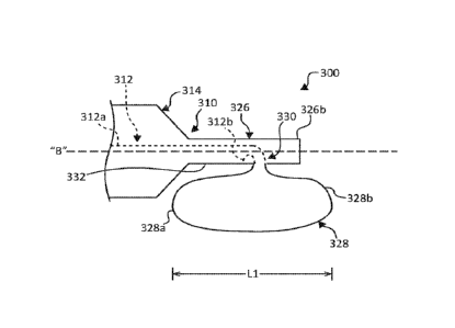
[0068] The
ophthalmic surgical instrument 300 generally includes a housing 310 and a
snare 312 operably coupled to the housing 310 for severing lenticular tissue.
The housing 310
of the ophthalmic surgical instrument 300 has a handle body 314 and a
cannulated body, such
as, for example, a hollow shaft 326 extending distally from the handle body
314. The hollow
shaft 326 is dimensioned for passage through a corneal incision and has a
proximal end 326a
integrally formed with or attached to the handle body 314, and a closed distal
end 326b. In
embodiments, the distal end 326b of the hollow shaft 326 may be open. The
hollow shaft 326
defines a central longitudinal axis "B" and defines a lateral opening 330 in a
lateral side surface
332 thereof. The lateral opening 330 is laterally offset from the central
longitudinal axis "B"
and defines an axis "C" therethrough that is perpendicular to the central
longitudinal axis "A"
of the hollow shaft 326. The lateral opening 330 may be any suitable shape,
such as, for
example, circular, elongated, square, or the like.
18
CA 03098658 2020-10-28
WO 2019/212940
PCT/US2019/029588
[0069] The
snare 312 of the ophthalmic surgical instrument 300 includes a first end
portion 312a and a second end portion 312b. The first end portion 312a of the
snare 312 is
movable relative to and within the hollow shaft 326 of the housing 310 via an
actuation
mechanism (not shown), similar to the actuation mechanism described above,
while the second
end portion 312b of the snare 312 is fixed relative to the housing 310. The
second end portion
312b of the snare 312 may be fixed to an inner surface of the hollow shaft 226
by crimping,
welding, adhesives, mechanical interlocks, or any other suitable structure or
method. In other
embodiments, both the first and second end portions 312a, 312b may be axially
movable.
[0070] The
snare 312 has a looped segment 328 protruding out of the lateral opening
330 in the lateral side 332 of the hollow shaft 226. The looped segment 328 of
the snare 312
is transitionable, via axial movement of the first end portion 312a of the
snare 312, between an
insertion or contracted configuration, as shown in FIG. 5A, and a deployed or
dilated
configuration, as shown in FIG. 5B. For example, a proximal retraction of a
lever (not shown)
of the housing 310 moves the first end portion 312a of the snare 312
proximally away from the
second end portion 312b of the snare 312, thereby reducing the diameter of the
looped segment
328. In contrast, a distal advancement of the lever moves the first end
portion 312a of the snare
312 distally toward the second end portion 312b of the snare 312, thereby
increasing the
diameter of the looped segment 328 of the snare 312. The looped segment 328
has a predefined
shape dimensioned to closely encircle a lens when the looped segment 328 is in
the dilated
configuration. In embodiments, both the first and second end portions 312a,
312b of the snare
312 may be movable to contract or dilate the looped segment 328.
100711 The
looped segment 228 defines a length "L" parallel with a central longitudinal
axis "B" defined by the hollow shaft 226. A majority of the length "L" of the
looped segment
328 is in side-by-side, parallel relation with the lateral side 332 of the
hollow shaft 326.
19
CA 03098658 2020-10-28
WO 2019/212940
PCT/US2019/029588
Further, a majority of the looped segment 328 (i.e., at least half) is
disposed proximally of the
distal end 326b of the hollow shaft 326. In this way, during use of the
ophthalmic surgical
instrument 300, the hollow shaft 326 hangs over a majority of the looped
segment 328, such
that the hollow shaft 326 sits on a lens during lens fragmentation to prevent
upward movement
of the lens as the looped segment 328 is constricted thereabout.
[0072] The
looped segment 328 includes a proximal section 328a disposed proximally
of the lateral opening 330, and a distal section 328b disposed distally of the
lateral opening
330. Both the proximal and distal sections 328a, 328b of the looped segment
328 are disposed
proximally of the distal end 326b of the hollow shaft 326 when the looped
segment 328 is in
the contracted configuration, as shown in FIG. 5A. When the looped segment 328
is in the
dilated configuration, the proximal section 328a of the looped segment 328 is
disposed
proximally of the distal end 326b of the hollow shaft 326, whereas a majority,
e.g., at least
about half, of the distal segment 328b is disposed proximally of the distal
end 326b of the
hollow shaft 326. As such, a majority of the looped segment 328 is disposed
alongside the
lateral side 332 of the hollow shaft 326 throughout the transition of the
looped segment 328
between the contracted and dilated configurations.
[0073] The
looped segment 228 is fabricated from shape memory materials, such as,
for example, a nickel-titanium alloy to allow the looped segment 228 to move
to its predefined,
dilated configuration. Other shape memory materials, such as shape memory
plastics are also
contemplated. in other embodiments, the looped segment 228 may be fabricated
from any
suitable biocompatible material including, but not limited to, stainless
steel, titanium, silicone,
polyimide, polyether block amide, nylon, polycarbonate, or combinations
thereof.
CA 03098658 2020-10-28
WO 2019/212940
PCT/US2019/029588
[0074] In
operation, a small incision in the edge of a cornea is made to provide access
to an anterior chamber and an anterior surface of a cataractous lens of a
patient's eye. A
capsulorhexis is made through the anterior surface of a lens capsule of the
patient's eye
providing surgical access to the cataractous lens. With the snare 312 of the
ophthalmic surgical
instrument 300 in the contracted configuration, as shown in FIG 5A, the hollow
shaft 326 of
the housing 310 is inserted through the corneal incision and the capsulorhexis
to position a
distal end portion of the hollow shaft 326 in an overlapping arrangement with
the anterior
surface of the lens, and position the looped segment 328 of the snare 312
adjacent the anterior
surface of the lens.
[0075] Once
the looped segment 328 is in the appropriate position, the first end portion
312a of the snare 312 is advanced distally, thereby transitioning the looped
segment 328 from
the contracted configuration to the dilated configuration, as shown in FIG.
5B. With the looped
segment 328 in the deployed configuration, the snare 312 is rotated about its
longitudinal axis
"B" (e.g., via rotation of the entire ophthalmic surgical instrument 300 or
via a rotation
mechanism (not shown)) to rotate the looped segment 328 circumferentially
about the lens to
encircle the lens and position the looped segment 328 relative to the lens so
that the plane
defined by the looped segment 328 bisects the lens. Upon rotating the snare
312 to the selected
position, the axis "C" defined through the lateral opening 330 in the hollow
shaft 326 extends
perpendicularly through a center of the eye, whereby the hollow shaft 326
overlaps with the
anterior surface of the lens and a majority of the looped segment 328 of the
snare 312.
100761 With
the looped segment 328 of the snare 312 disposed about the lens, and the
hollow shaft 326 overlaying and in contact with the anterior surface of the
lens, the looped
segment 328 is transitioned from the dilated configuration to the contracted
configuration,
dividing the lens into two hemispherical sections. During contraction of the
looped segment
21
CA 03098658 2020-10-28
WO 2019/212940
PCT/US2019/029588
328 about the lens, the looped segment 328 may exert a proximally-oriented
force on a distal
pole of the lens. However, since the hollow shaft 326 is in position over the
lens, the hollow
shaft 326 resists and/or prevents elevation and/or tilting of the distal pole
of the lens
notwithstanding the proximally-oriented force exerted thereon by the closing
snare 312.
[0077] After
one or more fragmentations of the lens by the ophthalmic surgical
instrument 300, the fragmented sections of the cataractous lens may then be
removed from the
eye using any suitable mechanism, such as, for example, an ultrasonic
aspirator.
[0078] It
will be understood that various modifications may be made to the
embodiments disclosed herein. Therefore, the above description should not be
construed as
limiting, but merely as exemplifications of various embodiments. Those skilled
in the art will
envision other modifications within the scope and spirit of the claims
appended thereto.
22