Note: Descriptions are shown in the official language in which they were submitted.
CA 03098715 2020-10-28
WO 2019/210330
PCT/US2019/029755
FLEXIBLE WIND TURBINE BLADE WITH ACTIVELY VARIABLE TWIST
DISTRIBUTION
Cross-Reference to Related Applications
[0001] This application claims priority to U.S. Provisional
Application No. 62/644,138,
filed on April 28, 2018, the disclosure of which is incorporated herein by
reference.
Field of the Disclosure
[0002] The present disclosure generally relates to a flexible wind
turbine blade which
actively twists during operation to maximize efficiency.
Background of the Disclosure
[0003] Wind power is the largest source of new renewable energy. In a two
year period
that spanned from 2015 to 2016, the global capacity of wind energy grew from
370 to 487 GW.
Recent concerns about climate change and the volatile cost of fossil fuels
have likely revived
interest in renewable energy, and wind energy continues to attract attention
as its costs decrease.
The reduced costs can be attributed to new technology. It has enabled a class
of wind turbines
that produce energy more effectively and at a lower cost. Examples of research
innovation
include variable rotor speed ("VRS") enabled by power conversion equipment and
novel gearbox
designs that increase wind capture. VRS increases the amount of wind converted
to electrical
power during partial load operation. VRS can be achieved by controlling the
generator torque
through the power conditioning equipment. It can also be realized through a
variable ratio
gearbox or continuously variable transmission ("CVT").
[0004] To maximize the benefits of VRS capability, it is beneficial
to control the rotor
speed in relation to the wind speed. Some researchers have worked on a
universal maximum
power point tracking ("MPPT") controller for small wind turbines. The MPPT
controller can
track the optimum point without using wind turbine characteristics. These
researchers used an
adaptive filter with a fuzzy logic based MPPT controller. Other researchers
controlled a doubly-
fed induction generator ("DFIG") using references given by an MPPT. These
researchers used a
second-order sliding mode to track the DFIG torque to reach the maximum power.
This work
suggests that this method is more accurate than tracking control currents.
Still others achieved
maximum performance by controlling power converters on both the grid and
generator side. This
1
CA 03098715 2020-10-28
WO 2019/210330
PCT/US2019/029755
works through the generator to control rotor speed for maximum power
production. On the grid
side, the active and reactive power are controlled by the current in the
direct and quadrature axes.
Some researchers used the MPPT in a turbine with a permanent magnet
synchronous generator
("PMSG") to extract the maximum power. Their system senses only DC link power
for this goal.
Other researchers proposed a control strategy to improve the MPPT efficiency.
The method is
based on the Radial Basis Function ("RBF") neural network and adjusts the
torque output with
changes in wind speed. Still others combined MPPT control with blade pitch
control to
maximize the extracted wind power. In this arrangement, only one controller
was used to reduce
system complexity and cost.
[0005] Aerodynamic efficiency has also been improved through the pitch
control and
blade deformation. Aerodynamic performance is dependent upon the selected
airfoil, tapering,
and twist distribution of the blade.
[0006] The application of control to the blade pitch angle and
generator torque has also
increased wind turbine performance. Another way to improve aerodynamic
efficiency is through
.. blade design, including the introduction of smart blades that deform during
operation. The
importance of wind turbine blade design was recognized by the International
Energy Agency
("TEA") as part of its midterm plan. The IEA pointed to a need for novel rotor
architecture that
will improve efficiency and facilitate on-site production.
[0007] Most current turbine blades have a fixed geometry. These
blades are not optimal
across the range of operational wind speed. Recently, a new generation of
morphing blades has
been the focus of research. These morphing blades passively change shape in
response to applied
forces. By changing shape, the blades can increase efficiency and reduce
vibration in comparison
to existing rigid blades. This type of blade is also less vulnerable to stall
and improves lift to drag
ratio. Morphing blades can also capture wind at lower wind speeds, and also
reduce force acting
on the rotor in extreme winds. Other research has focused on a wind turbine
blade with a flexible
flap assembly. This concept was found to significantly increase lift force,
and also helped in drag
reduction and power regulation. In another study, pitch control was combined
with control of the
trailing edge flap to reduce aerodynamic loads.
[0008] There has been a limited amount of work on blades with
provisions to change the
angle of twist during operation. One study offered a morphing segmented
concept. In this work,
blade segments are connected by screw sockets and a tension cable. The
equivalent force
2
CA 03098715 2020-10-28
WO 2019/210330
PCT/US2019/029755
between the cable tension and the centrifugal loads determines the effective
angle of attack.
Blade twist variation has also been the focus of research and development
related to helicopter
and tiltrotor blades. The latter features a versatile rotor design that allows
an aircraft to operate as
either a helicopter or an airplane. Each mode is associated with a unique
twist angle distribution
for maximum efficiency. Others have worked on the active control of the twist
angle for a
tiltrotor blade. After analyzing various approaches, they found the torque
tube actuation concept
to be the most practical, and tested it under loaded and unloaded conditions.
Even others have
studied a composite matrix with shape memory alloy wires that adjust the
proprotor twist
distribution. Still others have offered and tested a warp-twist concept for
helicopter and tiltrotor
blade. The design has a tubular spar with rotating ribs attached to the blade
skin. By warping the
skin, different twist angles could be obtained. Other researchers have focused
on a mechanism
that shifts the shear center of the profile to vary the twist distribution.
These researchers used a
clutch-like device to adjust thin internal walls to change the bending and
torsional shear stresses
distribution.
[0009] Additionally, the size of wind turbines has continued to increase in
recent years
with some systems having blades up to 75 m long. Blade size will continue to
grow as large wind
turbines produce energy at the lowest cost per watt. However, the large size
presents challenges
in manufacturing and transportation. The expense to move large blades from the
manufacturing
facility to the installation site can cost up to 5% of the total cost of an
installed turbine. There are
also several constraints on the trailers on public roadways in the United
States, including overall
dimensions and weight of the vehicle and load. Currently, the maximum blade
length that can be
transported on highways is 62 m. These constraints have driven designers to
look for other
design concepts and manufacturing techniques. Potential solutions include the
modularization of
blades and efforts to manufacture blades at the installation site. A first
company uses a space
frame design to make a modular blade. This blade includes three spars
connected by ribs and
non-structural skin. This company claims its new design results in a 7%
increase in average
annual energy, a 75% decrease in transportation costs, and a 50% increase in
service life,
compared to the current blades. A second company is also working on a 78 m
modular blade
with four sections. This blade has carbon spar boxes. Although this blade is
three meters longer
than Siemens B75, it has 10% lower mass. Despite the high price of carbon, the
design results in
a 3-5% reduction in the cost of energy.
3
CA 03098715 2020-10-28
WO 2019/210330
PCT/US2019/029755
[0010] Accordingly, there is a critical, long-felt need for a
flexible, modular, wind
turbine blade with actively variable twist distribution.
Brief Summary of the Disclosure
[0011] In an aspect of the present disclosure, a blade for a wind
turbine is presented. The
blade includes a spar and a blade arranged around the spar. The blade may
include a root, a tip,
and one or more sections, each section having a length, a stiffness ratio, and
one or more ribs.
Each rib may be configured to engage an actuator. Each section may further
include one or more
flexible segments, each flexible segment having a stiffness. The sections may
be carbon-
reinforced nylon. The spar may be rigid.
[0012] The blade may further include a plurality of boundary actuators,
each boundary
actuator positioned at a boundary formed by a pair of adjacent sections,
wherein each boundary
actuator is configured to engage the one or more ribs of the sections, and is
further configured to
twist the pair of adjacent sections forming the boundary.
[0013] The blade may further include a flexible skin arranged on the
blade.
[0014] The blade may further include a pitch actuator configured to rotate
the blade.
[0015] The blade may further include a root actuator configured to
twist the section
positioned at the root of the blade. The blade may further include a tip
actuator configured to
twist the section positioned at the tip of the blade.
[0016] The length and stiffness ratio of each section may be
optimized for maximum
efficiency during Region 2 operation. The boundary actuators may be configured
to twist the
blade into an optimized free shape. The free shape of the blade is the
geometry of the blade when
actuation is not applied during operation.
Description of the Drawings
[0017] For a fuller understanding of the nature and objects of the
disclosure, reference
should be made to the following detailed description taken in conjunction with
the
accompanying drawings, in which:
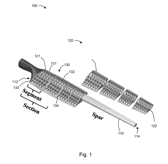
Figure 1 shows an embodiment of the presently disclosed wind turbine blade;
4
CA 03098715 2020-10-28
WO 2019/210330
PCT/US2019/029755
Figure 2 illustrates turbine blade properties on a model blade;
Figure 3 illustrates additional turbine blade properties on a model blade;
Figure 4 is a flow chart of a method for designing a blade;
Figure 5 is a flow chart of iterative calculations for Blade Element/Momentum
optimization;
Figure 6 is a flow chart of an iterative process for twist optimization of a
blade cross-section;
Figure 7 is a graph showing the search boundary for the optimal twist angle
configuration
design algorithm;
Figure 8 shows another embodiment of the presently disclosed blade;
Figure 9 is a graph showing an optimized blade assembly twist angle as a
function of
distance from the blade root relative to stiffness ratio;
Figure 10 is a flow chart of the iterative process to minimize the area
between ideal and
mechanical Twist Angle Distribution curves;
Figure 11 is a graph showing the difference between ideal and mechanically
possible Twist
Angle Distribution curves;
Figure 12 is a graph showing blade twist angle as a function of section
stiffness ratio, section
length, and actuator location;
Figure 13 is a flow chart illustrating an algorithm to determine an
advantageous shape of a
blade;
Figure 14 is a graph showing original and optimized TAD values for different
wind speeds;
and
Figure 15 is a graph showing the search range created by the original blade
TAD.
Figure 16: Range of transformation with respect to free position.
Figure 17: Power curve based on variable twist distribution blade.
Figure 18: Framework for active blade twist angle distribution.
Figure 19: Actuation energy required to reach from position "a" to position
"b".
Figure 20: Finding the optimum free shape to minimize the required actuation
energy for a
specific installation site.
Figure 21: Model showing drivetrain with blade control.
Figure 22: Actuators position assuming that optimal twist distribution for 5
m/s is free-shape
twist.
Figure 23: Structure for blade control.
Figure 24: Comparison of produced power during 24 hours by original and
modified twist
distributions.
5
CA 03098715 2020-10-28
WO 2019/210330
PCT/US2019/029755
Figure 25: Actuators position in a blade with 9 m/s twist for free shape.
Figure 26: Adaptively compliant wind turbine blade with out-of-plane twisting
capability.
Figure 27: Development environment for an aerodynamic adaptive structure.
Figure 28: Definition of the absolute twist angle, Wa , at distance, r, from
blade root.
Figure 29: A modular blade with flexible sections composed of two stiffness
regions.
Figure 30: Two blade segments with torsional stiffness k1 and k2 connected in
series. An
actuator provides a torque, T, to twist the segments.
Figure 31: Variation of twist within blade section. By varying the stiffness
ratio, R, the actual
twist angle (dotted line) can be optimized to approach the ideal twist angle
(solid curve).
Figure 32: Flowchart for optimization of actuator locations, P, and stiffness
ratios, R.
Figure 33: Ideal twist angle distributions, measured with respect to the
rotator plane.
Figure 34: Ideal and actual twist angle distributions using different
weighting schemes.
Optimal actuator locations are specified by markers.
Figure 35: Squared twist angle error, summed over all wind speeds, as a
function of distance
from the blade root.
Figure 36: Percent improvement in Cp as a function of wind speed, for all
weighting
schemes.
Figure 37: Wind turbine blades featuring (a) monolithic skin monocoque, (b)
single-shear
web, (c) double-shear web (box spar), and (d) rib and bulkhead design.
Figure 38: (a) small scale 3D printed blade for testing and (b) The modular
blade concept
using additively manufactured shells.
Figure 39: 3D model of the segment.
Figure 40: Computational framework for design and analysis.
Figure 41: Definition of twist angle, tp, at distance, d.
Figure 42: The classical BEM iterative calculations flowchart.
Figure 43: The design space exploration algorithm.
Figure 44: Schematic for a one way F SI simulation.
Figure 45: Air volume surrounding the blade segment.
Figure 46: Pressure distribution over the blade segment.
Figure 47: Plots showing the minimum, maximum and free positions of the
flexible blade.
Figure 48: The free-shape cross-section (-.-) compared to the twisted section
(X), (a) as it
occurs, (b) with the chord lines aligned.
Figure 49:
6
CA 03098715 2020-10-28
WO 2019/210330
PCT/US2019/029755
Figure 50:
Detailed Description of the Disclosure
[0018] Although claimed subject matter will be described in terms of
certain
embodiments, other embodiments, including embodiments that do not provide all
of the benefits
and features set forth herein, are also within the scope of this disclosure.
Various structural,
logical, process step, and electronic changes may be made without departing
from the scope of
the disclosure.
[0019] In an aspect of the present disclosure, a blade 100 for a wind
turbine is presented.
The blade 100 includes a spar 110. The spar 110 has a blade axis along a
longitudinal length
from a root end 112 (a proximal end¨at or near the hub of a turbine) to a tip
end 114 (e.g., a
distal end¨at or near an outer circumference of the turbine). The spar 110 may
be rigid. The
rigidity of the spar 110 may be dependent upon the mass and scale of the blade
100, or the mass
and scale of any combination of the components of the blade 100. The spar 110
provides the
required strength to prevent structural failure of the blade 100. The spar 110
may be formed from
fiber-reinforced composites having, for example, s-glass and h-glass fibers
and thermoset
matrices (such as, for example, epoxies, polyesters, and vinyl esthers). Other
suitable materials
can be used and will be apparent to one having skill in the art in light of
the present disclosure. In
some embodiments, the spar 110 may be tapered along its length. For example, a
spar 110 may
have a cross-sectional area which becomes smaller towards an outer (tip) end
114 of the
spar 110.
[0020] The blade 100 includes a blade body 120 arranged around the
spar 110. The blade
body 120 may form an airfoil shape of the blade 100¨i.e., the blade body 120
may have a cross-
sectional shape (viewed at a point along the blade axis) so as to act as an
airfoil. The blade
body 120 has a body section 130 spanning a length along the blade axis between
two boundary
ends 133,134. Each boundary end 133,134 is configured to engage with a
corresponding
boundary actuator. For example, two boundary actuators may be provided, each
boundary
actuator attached to a corresponding one of the boundary ends 133,134 of a
body section 130. In
some embodiments, one or more of the boundary ends 133,134 may include a rib
135 and the
rib(s) 135 may be configured to attach to a corresponding boundary actuator.
7
CA 03098715 2020-10-28
WO 2019/210330
PCT/US2019/029755
[0021] The body section 130 may have a first segment 131 extending
along a first
portion of the length, the first segment 131 having a first stiffness. The
body section 130 may
further include a second segment 132 attached to the first segment 131 and
extending along a
second portion of the length of the spar 110. The second segment 132 has a
second stiffness. The
second stiffness may be the same or different from the first stiffness. In
this way, the body
section 130 may be said to have a stiffness ratio relating the first stiffness
and the second
stiffness. Each body section 130 may further include one or more segments
131,132. Each
segment 131 has a stiffness which may be the same or different from other
segments 131. In this
way, for example, the stiffness ratio of a body section 130 having two
segments 131,132 may be
defined as the stiffness of the second segment 132 divided by the stiffness of
the first
segment 131. The stiffness of each segment 131,132 may vary between 10 to 100
N/m based
upon the segment 131 location and scale. However, the stiffness may be more
than or less than
this range. The area between two segments 131,132 within a single body section
130 may be
further defined as a transition plane 150. In some embodiments, a rib 135 is
bonded to each
segment 131 at the transition plane 150. Such a rib at the transition plane
may not be connected
to an actuator (e.g., the rib may be free to rotate about the spar 110).
[0022] Some embodiments of a blade body 120 may include includes two
or more body
sections 130. Each body section 130 has a section length along the primary
axis. Adjacent
boundary ends of adjacent body sections may engage with a common boundary
actuator. In this
way, a single boundary actuator may twist two adjacent body sections 130 at
the adjacent
boundary ends 133,134. Each body section 130 has a stiffness which may be
constant over the
section length or may vary over the section length. Where the stiffness varies
over the section
length, the overall stiffness of the body section 130 may be represented as a
stiffness ratio. For
example, the stiffness ratio of a body section 130 may be defined as a
stiffness at a distal
boundary end 134 of the body section divided by a stiffness at a proximal
boundary end 133 of
the section. The body sections 130 may be made from plastics, for example,
thermoplastics such
as, for example, carbon-reinforced nylon. Other materials, either alone or in
combination, may
be suitable for the body section(s) and will be apparent to one having skill
in the art in light of
the present disclosure. The stiffness of the body section 130 may be defined
by the material of
the body section 130, the overall shape of the body section 130, and/or the
internal structure of
the body section 130, etc. For example, the body section 130 may be solid or
may have an
internal structure including voids (internal volumes of air or other material
different from the
8
CA 03098715 2020-10-28
WO 2019/210330
PCT/US2019/029755
section material), and/or a regular or irregular framework of the section
material. For example,
the embodiment of Figure 1 includes a box-like or "waffle" framework. The body
sections 130
may be made from fiber-reinforced composites comprising carbon or Kevlar
fibers and
thermoset matrices. The body sections 130 may be produced using Additive
Manufacturing
("AM") techniques or otherwise.
[0023] In some embodiments, a rib 135 may be bonded to each end of a
body
section 130. In some embodiments, the ribs 135 have a shape which matches the
cross-sectional
shape of the body section(s) 130 to which each rib 123 is bonded. In this way,
the overall shape
of the bladebody 120 may continue over its length without disruption at the
rib(s) 135. Where a
rib 135 is located between two body sections 130, the rib 135 may be bonded to
each body
section 130. The rib(s) 135 may be rigid. The ribs 135 may be made of the same
materials as the
spar 110 or a different material. Each rib 135 may be movable, for example,
rotatable. In
particular, each rib 135 may be configured to be rotatable about the spar 110.
With reference to
Figure 8, a blade 200 may include one or more boundary actuators 140. Each
boundary
actuator 140 may be positioned at a boundary end 160. As stated above, in some
embodiments, a
boundary actuator 140 may engage adjacent boundary ends 160 such as the
boundary ends 160
formed by a pair of adjacent sections 170. In some embodiments, a boundary
actuator 140 may
be configured to engage a rib 165 at a boundary end 160. In some embodiments,
a boundary
actuator 140 may be configured to engage a rib between adjacent boundary ends
160. In this
way, each rib 165 may be moved (e.g., rotated about the spar). Such movement
may cause the
corresponding body sections 170 to move. For example, where a rib 165 bonded
to a distal end
of a body section 170 is rotated more than a rib 165 bonded to a proximal end
of the body
section 170, the body section 170 is caused to twist. The twist of the body
section 170 may be
uniform (for example, where the cross-sectional area and stiffness are
constant over the section
length) or non-uniform (for example, where the cross-sectional area and/or
stiffness vary over
the section length, for example, at different segments of a body section). In
some embodiments,
one or more ribs 165 of the blade 100 will be engaged with a boundary actuator
140, while one
or more other ribs 165 will not be engaged with a boundary actuator 140.
[0024] The blade 100 may further include a deformable skin 180
arranged on the
blade 120. The deformable skin 180 may be nonstructural (i.e., does not
contribute significantly
to the strength of the blade). The deformable skin 180 may be made from any
suitable material,
such as, for example, neoprene, graphene, or polyurethane.
9
CA 03098715 2020-10-28
WO 2019/210330
PCT/US2019/029755
[0025] The blade 100 may further include a pitch actuator configured
to rotate the
blade 100. The pitch actuator may be located at the root end 121 and connected
to a hub. For
example, the spar 110 may be connected to the pitch actuator such that the
pitch actuator may
rotate the spar around its primary longitudinal axis, thereby rotating the
blade 100.
[0026] The blade may further include a root actuator configured to twist
the section
positioned at the root of the blade. The blade may further include a tip
actuator configured to
twist the section positioned at the tip of the blade. In some embodiments, the
root actuator and/or
the tip actuator may be boundary actuators.
[0027] The length and stiffness ratio of each body section 130 may be
enhanced for
improved efficiency during Region 2 operation (the operation mode below the
rated speed of the
turbine, where it is desirable to maximize the power extracted from the wind).
The boundary
actuators 140 may be configured to actively twist the blade body 120 during
Region 2 operation
to optimize the Twist Angle Distribution ("TAD") of the blade 120. The TAD
describes the twist
angle of the blade 120 as a function of blade length. The TAD may be defined
for discrete points
along the length of the blade 120. The TAD may vary as a function of wind
speed. Techniques
for designing and controlling a blade with advantageous TAD and other blade
parameters are
provided below and in the attachments.
EXAMPLE 1
[0028] This non-limiting example provides a description of the
function, composition,
and methods of design and manufacture of an exemplary flexible blade with
actively variable
twist distribution according to an embodiment of the present disclosure.
[0029] The exemplary blade uses an additive manufacturing ("AM")
process to make the
blade segments that will be incorporated into the modular design. The
exemplary design has
multiple benefits that support the International Energy Agency ("TEA") vision.
It can facilitate
the production of blades needed for a new generation of large wind turbines.
Implementation of
this free-form process will eliminate the need for large molds and the
associated blade
production facility. As further described below in Section F, in some
embodiments, blades may
be manufactured at the installation site. AM also provides new capabilities in
blade design. It can
create complex geometries and components with directional properties. In some
embodiments,
the present disclosure provides structures with a low torsion-to-flexural
stiffness ratio. This gives
CA 03098715 2020-10-28
WO 2019/210330
PCT/US2019/029755
rise to the implementation of a flexible blade with an actively variable TAD.
The TAD describes
the twist angle of the blade as a function of blade length. It can be set
through the placement of
the actuators and the design of AM blade sections/segments with a desired
stiffness. This
capability can mitigate system vibration, facilitate the removal of blade ice,
and increase
aerodynamic efficiency. The development of this technology is the major focus
of this
disclosure. However, the work in this disclosure also provides a design
methodology for an
active variable TAD that increases Region 2 efficiency. It includes (1) an
aerodynamic analysis
that establishes the TAD of the blade, (2) a mechanical design technique that
defines the
placement of blade actuators and the relative stiffness of the blade sections,
and (3) a method of
establishing the free-shape of the blade¨the shape when no actuation is
applied.
Flexible Blade Concept
[0030] A modular blade has been devised as shown in Fig. 1. In some
embodiments, the
primary components include a spar, surrounding segments, and a non-structural
skin. The spar is
rigid, while the body segments and skin are flexible. These segments may work
together in pairs
to form sections, which are mounted onto the spar in series. Actuators are
used to twist the blade
into the desired TAD. A pitch actuator performs gross adjustment by rotating
the spar. The
remaining actuators are mounted at the section boundaries to provide fine
adjustment to the TAD
along the length of the blade. The placement of actuators, length of the
sections, and compliance
of the segments are crucial in obtaining the required TAD. The proposed
framework selects the
optimal values for these parameters to maximize energy production.
Twist Angle Distribution
[0031] The spar is connected to the hub through a pitch motor that
grossly adjusts the
blade angle. The angle of rotation for the spar, (Pp, is the same as the
conventional pitch angle as
shown in Fig. 3. It has an axis at the hub connection and is measured relative
to the rotor plane of
motion. Along the length, r, of the blade the local twist angle, cob, is
measured relative to the
blade root axis. Since the blade root moves with pitch actuation, the absolute
local twist angle is
measured using,
(1)(r) = p b (r) (1)
11
CA 03098715 2020-10-28
WO 2019/210330
PCT/US2019/029755
where co represents the angle of twist measured relative to the rotor plane of
motion at length, r,
from the hub center.
Methodology
[0032] In some embodiments, the framework utilizes three main blocks
shown in
Figure 4. The process commences using a given blade design of known geometry
and
aerodynamic performance. The aerodynamic design establishes the TAD for
discrete points of
wind data that span Region 2. Each selection represents the TAD that provides
maximum
aerodynamic efficiency at the given wind speed. The mechanical design locates
the actuators and
establishes the stiffness ratio between the blade segments in each section.
These parameters
determine the shape of the blade as it is deformed. An optimization procedure
identifies values
that create the TADs found in the aerodynamic design. The last step of the
procedure determines
the free shape of the blade. This is the geometry of the blade when it is not
deformed.
Computational tools are employed in the framework to conduct the procedure.
These include the
National Renewable Energy Laboratory (NREL) Aerodyn software, a genetic
algorithm, and a
parallel computing network. The steps of the framework are described in detail
in subsequent
paragraphs.
Case Study
[0033] A case study has been conducted to demonstrate the proposed
optimization
method. It is based on a 20 kW wind turbine that was used in the National
Renewable Energy
Lab (NREL) Unsteady Aerodynamics Experiment Phase VI experiment. This is a
fixed-speed
horizontal axis system with two blades. Each blade has a length of 4.6 m with
a maximum chord
length of 0.714 m. It has a rotor speed of 72 RPM that achieves a torque of
2650 Nm at a rated
speed of 13.5 m/s. This simple system was a good starting point for studying
of the blade twist
angle. The performance data for this blade has also been certified by NREL. It
is used to
characterize the aerodynamic performance of the blade with respect to the TAD.
An analysis is
also conducted on the original (rigid) blade to establish a baseline for the
performance.
Aerodynamic Design
[0034] The aerodynamic design procedure determines the appropriate
TAD of the blade
as it varies in relation to wind speed. The objective is to maximize the
efficiency of the wind
12
CA 03098715 2020-10-28
WO 2019/210330
PCT/US2019/029755
turbine blade in Region 2. This is measured in terms of the power coefficient,
cp. The efficiency
is maximized as a function of the pitch angle, twist angle configuration, and
wind speed, v, such
that:
c = f(cp,v) (2)
[0035] In the aerodynamic design the twist angle, (p is analyzed at
discrete points along
the blade. The variable (pa represents the angle of twist with respect to the
rotor plane at these
points:
Pa(i) = koa(1), coa(2), coa(Na)1
(3)
[0036] The aerodynamic portion of the framework includes a solver
tool and
aerodynamic model. This arrangement is used to evaluate the performance of
various twist angle
configurations.
Aerodynamic Model
[0037] AeroDyn was used to study the aerodynamic performance of the
blade. It is a
time-domain module that can compute the aerodynamic response of wind turbine
blades. It
requires an iterative nonlinear solution. In our model, it simulates the
steady loads on the blades.
These loads can be used to determine the amount of torque that is produced by
the rotor. The
approach is based on the quasi-steady Blade-Element/Momentum ("BEM") theory.
The BEM
method is known for efficiency and the ability to provide reliable blade load
results. It equates
the terms for thrust force and torque from momentum theory and blade element
theory. It then
solves the equations for the axial and angular induction factors:
a =
___________________________________________________________________________
(4)
4Qcos20 +1
o-1 (Cisin 0+C dcos 0)
a' = _________________________________ 4Qs
(5)
in 0 cos 0 +1
o-1 (Cicos 0¨C dsin 0)
[0038] These equations are used for each blade element in the
iterative process, which is
illustrated in Fig. 5. The BEM technique analyzes the the blade as individual
elements. The
iterative process is used on each element to calculate the aerodynamic loads.
Ultimately, the
results are combined to provide the aerodynamic loads on the blade and rotor.
In the case study,
the blade cross-section was evaluated at 19 points along the length.
13
CA 03098715 2020-10-28
WO 2019/210330
PCT/US2019/029755
Search Algorithm
[0039] In Region 2, the optimal twist angle configuration may be
found by maximizing
the power coefficient. The BEM model is coupled with an optimization tool to
search for a twist
angle configuration. The MATLAB environment is used to create this computing
structure in the
case study. It is used to find the optimal TAD for a discrete range of wind
speed, v, in Region 2,
such that,
v(j) = [v(1), v(2), . , v (N v)]
(6)
where the first and last points in the set correspond to the cut-in and rated
speed, respectively.
[0040] The iterative search algorithm finds the twist angle that
maximizes the power
coefficient at each cross-section. The blade calculations are nonlinear and
discontinuous, and the
search procedure is computationally expensive. A Genetic Algorithm ("GA")
solver is used as
the search tool to identify optimal twist configurations. The calculation
steps for finding the twist
angle of a cross-section at a given wind speed are described by the flowchart
shown in Fig. 6.
[0041] The GA has capabilities in solving problems with
discontinuous, non-
differentiable or highly nonlinear objective functions. Still, the process
indicated that there were
local minima. This makes it difficult for the GA solver to find the global
minimum. However,
the preliminary work demonstrated that the global minimum always existed
within a band of
values that surround the original twist angle. Hence, a range of values can be
used to constrain
the search as illustrated in Fig. 7. For each cross-section the procedure
begins searching near the
original design twist distribution. After that, the resulting solution for the
twist angle may be
used to form the search domain of next step. The constraint narrows the search
domain and
allows the GA to find the global solution more efficiently. This procedure is
repeated until the
power coefficient no longer increases. This corresponds to the optimum blade
twist for the given
wind speed.
Mechanical Design
[0042] The previous section determined an ideal TAD to maximize the
aerodynamic
efficiency. This section presents a technique to obtain the selected TADs
through mechanical
design. The aim is to achieve a TAD in the actual application that matches
that found in the
aerodynamic design. During operation, the TAD will be actively controlled in
relation to wind
14
CA 03098715 2020-10-28
WO 2019/210330
PCT/US2019/029755
speed. The blade is coerced into the desired shape by internal actuators. The
blade segments
could be additively manufactured from a flexible material such as carbon-
reinforced nylon. A
design technique in which the component stiffness is defined by the AM process
and internal
geometry is currently being investigated. For this analysis, the stiffness is
considered in relative
terms, or as a ratio between consecutive segments. The mechanical design
establishes the
stiffness ratios for each blade section and location for the intermediate
actuators. The
calculations concern blade deformation and, therefore, is conducted with
respect to the blade
axis. Optimization principles are implemented into this process to leverage
the capability of the
mechanical design.
Blade Model
[0043] The exemplary blade configuration for the design process is
shown in Fig. 8. The
blade is constructed through a series of flexible blade segments that are
spliced together and
mounted on the spar. Two consecutive segments form a section. The segments,
Sc,), in each
section have different torsional stiffness values. Each segment has a
stiffness of k, where is
the section number, and 77 is the segment number. The latter subscript is
either 1 or 2, for the first
and second segments of each section, moving from root towards the tip. The
boundary between
these two segments in each section is denoted by the transition plane. This
point is referred to as
a transition plane since the stiffness value changes across this point. An
actuator is located at the
boundaries of each section which are identified by the actuator planes. A
single actuator acts at
each of these points to twist the respective ends of the sections into shape.
[0044] There are two types of design input variables for the
optimization problem. One is
the stiffness ratios, Rk , for each section, which is defined as:
k<,2
Rk = - (7)
k<.1
where ko_ and k2 refer to the stiffness values for segments 1 and 2,
respectively, in section (.
The other design input defines the length of each section (, and hence, the
locations, rp, of the
intermediate actuators at P = {3,5,...,2N cl}. The first and the last
actuators at P = {1, 2Ak+1},
are fixed near the root and at the tip of the blade and are not part of the
analysis. The section
lengths and the relative stiffness between the segments are crucial in
determining the TAD. The
relationship between the design inputs and the TAD for a single section is
illustrated in Fig. 9.
CA 03098715 2020-10-28
WO 2019/210330
PCT/US2019/029755
An ideal TAD is described by the solid curve, while the possible mechanical
design scenarios are
indicated by the dotted lines. Twist angle of the corresponding transition
plane can move along
the dashed line depending on the stiffness ratio. Decreasing the stiffness
shifts the mechanically
achievable TAD curve upwards. Increasing the ratio has the opposite effect.
The mechanical
design can also be shifted to the left and right along the ideal curve by
adjusting the segment
length, and thus, actuator locations.
Optimization Problem
[0045] The goal of the optimization process is to identify a
mechanical design that
closely matches the results found in the aerodynamic design. It works by
minimizing the area
between the respective TAD curves. Figure 10 illustrates how the objective
function is applied to
this problem.
[0046] The optimization process minimizes the total area for all of
the sections across the
range of wind speed in Region 2: This is stated through the objective
function, f,
f=
Nv
Z= A U)
j=i v (8)
where, Av is the area between the TAD curves of the theoretical and mechanical
design as
computed at wind speed, v(j). The total area, Av is computed for a given wind
speed using,
AU) = fr ((N)19)
v r (Pb,a(rj) dr (9)
where (pb,a and cob3n represent the ideal and mechanical design TAD,
respectively, in the blade
coordinate system, at distance, r, for wind speed j. Figure 11 illustrates an
example of the area
that is found between the two TAD curves. Ultimately, the area is measured
over the active
portion of the blade. This portion extends from the start of the first
section, at r(p1) through the
end of the last section at a distance of r(p=2+1).
[0047] The twist values at the actuation planes are obtained from the
theoretical TAD.
The following relationship is used to compute the twist angle at the
transition planes, where P =
{2, 4,...,2(1
Tb,m(r(p-i),/)+Rkx(pb,m(r(p+i),i)
(Pb,m(r(P), j) = i+Rk (10)
16
CA 03098715 2020-10-28
WO 2019/210330 PCT/US2019/029755
[0048] Preliminary work demonstrates that the stiffness ratio, Rk,
can always be found
within a given range. Hence, a constraint was imposed to reduce the range of
design inputs:
Rk,min Rk Rk,max (11)
[0049] Constraining the lengths of segments in each section reduces
the computational
expense and also provides reasonable results for the analysis.
= /2 (12)
where / represents the lengths of segments in section (.
[0050] The efficiency of the search algorithm can be further improved
by establishing a
search domain for the actuator location. The midpoints of the search domains
are located at
evenly spaced points along the active portion of the blade. These points are
established by
dividing the active portion of the blade into Ak section. The range for the
individual domains is
extended a distance of b to both sides of the respective starting point. The
constraint placed upon
the search domain is as following:
Bp b rp Bp + b, for P = (13)
where,
P-1 r(p=g+i)-r(P=i)
Bp = 2 X ro, =1) (14)
[0051] Once the constraints are applied, the value of the objective
function is calculated
for all possible combinations of design input parameters. It considers all of
the discrete wind
speed values, v, in Region 2. The values of Rk , and the lengths of the
sections (as defined by the
locations of intermediate actuators planes) are selected through this process.
These inputs
correspond to the design solution that minimizes the objective function.
[0052] In the case study, four sections were sufficient for creating
the TAD. The stiffness
ratio, Rk, was constrained between 0.5 and 2 with a step size of 0.1. The
search domain, b,
spanned 5% of the active length of the blade with a step size of 1% of the
length. Five actuators
.. are implemented to create the TAD. This arrangement created 87.3 million m(
sNs-1) design
scenarios to consider. Figure 12 shows how the parameters for a typical
combination are
17
CA 03098715 2020-10-28
WO 2019/210330
PCT/US2019/029755
implemented to acquire the TAD. The objective problem was analyzed through a
parallel
computing cluster, having 132 cores that took roughly 50 hours to process.
Free Shape Selection
[0053] The final step in the design process is to select a TAD
scenario for the free
position. This will correspond to the geometry of the TAD when it is not
deformed by the
actuators, or when no load is applied. In this approach, the selected free
position is the TAD that
minimizes the maximum required twist change per length unit. Using this
criterion reduces the
required amount of travel and load applied by the actuator.
[0054] The process for finding the free shape TAD is illustrated in
Fig. 13. Here the TAD
at wind speed, v(i), is compared to each wind speed, v(j). The goal is to find
the TAD at v(i),
which requires the least amount of deflection with respect to the other wind
speed TADs.
Accordingly, the first step of the algorithm considers the TAD at v(i) as the
free position,
(pb,n,i(r(p), 1:). Then, the amount of twist deformation, (pb,m(r(p),j), to
reach the TAD at all other
wind speeds, v(j), is determined. This is calculated in terms of the two ends
of each individual
blade segment .5"71, ô1 (s) and ô1 (s + 1), (s = 2(( ¨ 1) + ri). The
difference between required
twist change for two ends of each segment is divided by the length of that
segment, r (p=s+i) ¨
r(p=s). The result is the required twist change per length unit for that
segment, (5'71:
:( +1)-so(s)
dii (s) = (15)
r(P=s+1)¨r(P=s)
where,
(s) = (Pb,m(r(P), i) (Pb,m(r(P),/) i,j E [1,2, ...., Nv], j #j
(16)
[0055] The difference, (5'71 is computed for all wind speeds. The
segment with the
maximum absolute value of 6' is picked as the most critical one for this
assumption. This process
is repeated until i spans the whole discrete range of wind speed, v, in Region
2. It results in a list
of assumed free shapes (assigned to each wind speed) and a corresponding
maximum absolute
values of ô'. Finally the assumed free shape with the smallest maximum
absolute values of 6' is
selected as the optimum free shape.
18
CA 03098715 2020-10-28
WO 2019/210330
PCT/US2019/029755
Results
[0056] The design methodology for the flexible blade was demonstrated
through a case
study. Blade performance data was obtained from the NREL Unsteady Aerodynamics
Experiment Phase VI experiment. The aerodynamic analysis combined the NREL
Aerodyn
software with a genetic algorithm to establish the TAD. This was done for a
discrete set of wind
speed that ranged from cut-in to rated speed (Region 2). At each point a
genetic algorithm
identified the TAD that maximized the power coefficient. Constrained
optimization was
subsequently used in the mechanical design. It established the actuator
locations and stiffness
ratios of the segments in each section. The design objective was to match the
TAD curve found
in the aerodynamic design. The performance of the TAD created by the
mechanical design was
compared to that of the aerodynamic design. The difference in efficiency was
approximately
0.08%. The small amount of loss suggests that the mechanical design strategy
was effective.
Table 1: Optimal locations for actuators
Actuator points, P P1 P3 PS P7 P9
Location, r [m] 1.23 2.24 2.94 4.10
5.02
Table 2: Optimal stiffness ratios
Section, 1 2 3 4
Stiffness ratio, Rk[-N/m1 1.1 2 1.5 0.7
N/m
[0057] The actuators locations and relative stiffness values are
given in Tables 1 and 2,
respectively. The ratios that are closest to unity will have a twist
distribution that is more linear
between the respective actuators. Conversely, the ratios away from unity
represent sections
where the change in the twist angle is less linear. The mechanical design
results for the TAD
were used to find the best free shape for the blade. The selection procedure
found that the free
shape should be the same as the TAD that is used when the wind speed is near 9
m/s. For this
TAD the maximum change in twist occurs in segment S21. It only necessitates a
range of 1.96
degrees about the free-shape TAD. Recall that the pitch actuator is used for
corse positioning of
the blade. Therefore, the blade deformation that tweaks the TAD only occurs
with respect to the
blade axis. This technique reduces the required amount of rotational
deflection.
19
CA 03098715 2020-10-28
WO 2019/210330
PCT/US2019/029755
[0058] Figure 14 shows the selected TAD for various points of wind
speed in Region 2.
The values correspond to the TAD as measured with respect to the hub axis.
Each TAD in the
plot achieves the maximum aerodynamic efficiency for the given wind speed. In
the plot it is
observable that the greatest amount of required variation occurs nearest the
blade root. The
amount of difference emphasizes the significance of the actively variable
capability.
Table 3: Maximum power coefficients for the original and modified TADs
v,,,, [m/s] 5 6 7 8 9 10 11 12
13
cpo [-] 0.447 0.484 0.435 0.370 0.314 0.268
0.231 0.200 0.174
cp, [-] 0.464 0.489 0.440 0.377 0.315 0.270
0.233 0.204 0.180
Increase [%] 3.83 1.05 1.13 1.76 0.13 0.63 1.08
1.90 3.27
[0059] The performance of the original blade wuõ411õclaATAgkc,c1. In
this case the
power coefficient was maximized by adjusting the pitch angle. The results for
the original blade
are used to establish a baseline for the performance of the NREL blade. Table
3 compares the
efficiency, cpt, of the proposed blade design to that of the original, cpo.
The flexible blade with
an active variable twist angle provides the greatest benefits near cut-in and
rated speed, where
the power coefficient increased by 3.83 and 3.27%, respectively. The amount of
increase
becomes less pronounced around the wind speed of 9 m/s. This is likely near
the design speed of
the original blade. It is reasonable to expect the TAD to already be optimal
at this point. The
AeroDyn computations also revealed that the flexible blade also has a lower
cut-in and rated
speed than that of the original blade. By actuating the blade it is possible
to reduce the cut-in
speed from 13.5 to 13.2 m/s, while the rated speed drops from 5 to 4.9 m/s.
Conclusion
[0060] A methodology was presented for designing a flexible blade with an
actively
variable twist angle. It enables the blade twist angle to be adjusted, which
maximizes the
aerodynamic efficiency in Region 2. The exemplary design concept is based on
the use of
flexible blade sections which are deformed by actuators on each end. The
exemplary design
procedure finds the optimum TAD through a genetic algorithm that evaluates
performance data
obtained from the NREL Aerodyne software. Design optimization is then employed
to set the
actuator locations and material stiffness ratios. It establishes the
mechanical means that is
necessary to create the TAD in the application. A case study was performed
using Aerodyne
with data acquired from the NREL Unsteady Aerodynamics Experiment Phase VI
experimental
CA 03098715 2020-10-28
WO 2019/210330
PCT/US2019/029755
wind turbine. The performance of the presently-disclosed blade design was
compared to that of a
conventional blade with pitch adjustment. The results indicate that the
flexible blade and
associated design technique boosts the aerodynamic efficiency. The increase is
most noticeable
at the cut-in and rated speeds, where the power coefficient increased by 3.8%
and 3.3%,
respectively. Embodiments of the presently-disclosed design also enable a
slight reduction in the
wind speeds at which cut-in and full-power occur.
Nomenclature
A, total area between TAD curves
Cd drag coefficient
lift coefficient
total number in the set
segment endpoint locations
correction factor
Rk stiffness ratio
segment number
a axial induction factor
a' angular induction factor
twist range in one direction
power coefficient
wind speed index (free-shape selection)
wind speed index
stiffness constant
1 segment length
TAD iterative index
radial distance
wind speed
6 cross-section twist variation
Twist change gradient
0 relative flow angle
twist angle
local solidity
a aerodynamic analysis, subscript
blade coordinate system, subscript
min minimum, subscript
max maximum, subscript
pitch, subscript
71 segment number, subscript
section number, subscript
[0061] Further discussion including various embodiments and examples
of the present
disclosure are provided below in Sections A¨F. The discussions, embodiments,
and examples are
intended to be illustrative and non-limiting.
21
CA 03098715 2020-10-28
WO 2019/210330
PCT/US2019/029755
A. MODELING AND DESIGN METHOD
[0062] An exemplary modeling framework to analyze a wind turbine
blade subjected to
an out-of-plane transformation is presented in this section. One having skill
in the art will
recognize that the framework is non-limiting, and other frameworks may be
devised. The present
.. framework combines aerodynamic and mechanical models to support an
automated design
process. The former combines the NREL AeroDyn software with a genetic
algorithm solver. It
defines the theoretical twist angle distribution (TAD) as a function of wind
speed. The procedure
is repeated for a series of points that form a discrete range of wind speed.
This step establishes
the full range of blade transformation. The associated theoretical TAD
geometry is subsequently
passed to the mechanical model. It creates the TAD geometry in the context of
an embodiment of
the disclosed wind turbine blade concept. In some embodiments, the blade
sections are assumed
to be made by additive manufacturing, which enables tunable stiffness. An
optimization problem
minimizes the difference between the practical and theoretical TAD over the
full range of
transformations. It does so by selecting the actuator locations and the
torsional stiffness ratios of
.. consecutive segments. In the final step, the blade free shape (undeformed
position) is found. The
model and design support out-of-plane twisting, which can increase energy
production and
mitigate fatigue loads. The presently-disclosed framework is demonstrated
through a case study
based on energy production. It employs data acquired from the NREL Unsteady
Aerodynamics
Experiment. A set of blade transformations required to improve the efficiency
of a fixed-speed
system is examined. The results show up to 3.7% and 2.9% increases in the
efficiency at cut-in
and rated speed, respectively.
A.1. Introduction
[0063] Wind energy continues to be the largest source of new energy
added to the energy
production portfolio. In a two year period that spanned from 2015 to 2016, the
global capacity of
.. wind energy grew from 370 to 487 GW. The growth has occurred for a variety
of reasons. There
are concerns due to climate change and the volatility of fuel cost. The cost
of wind energy has
also decreased and now rivals that of energy produced by coal-burning power
plants. The
reduced cost can be attributed to new technology. It has enabled a class of
wind turbines that
produce energy more effectively and at a lower cost. Examples of research
innovation include
.. variable rotor speed enabled by power conversion equipment and novel
gearbox designs that
22
CA 03098715 2020-10-28
WO 2019/210330
PCT/US2019/029755
increase wind capture. Aerodynamic efficiency has also been improved through
the pitch control
and blade deformation.
[0064] Aerodynamic performance is dependent upon the selected
airfoil, tapering, and
twist distribution of the blade. The design configuration depends upon system
size, type of
operation (i.e., fixed versus variable speed), and the wind conditions at the
installation site. There
has also been an interest in blades that are designed to transform shape
during operation. Some
researchers used a computational model to study the performance of flexible
blades that deform.
The blades achieved a higher lift-to-drag ratio and delayed stall. Other
researchers equipped a
turbine blade with a flexible flap assembly rather than changing the entire
cross section. This
capability has also provided an increase in the lift-to-drag ratio. The work
of still other
researchers made similar findings for a flexible flap. Moreover, the
researchers demonstrated
how the flap could control stall phenomena. The researchers also discovered
that morphing
blades have the ability to "self-start" whereas traditional blades require a
higher initial moment.
This dynamic can reduce thrust forces at extreme winds and when the system is
parked. By
affecting the load dynamics, the blades are also able to mitigate vibration.
Other researchers
coordinated the control of the trailing edge flap with that of the blade pitch
angle. The study
suggests the technique can reduce the rotor thrust load.
[0065] Out-of-plane blade twisting can also improve wind turbine
performance.
Researchers have studied small wind turbine blades with a variable twist
angle. The authors used
cables to actuate three ribs to adjust the twist angle distribution. An
electric motor in the rotor
hub moves the cables. Other researchers offered a segmented morphing concept.
In this
approach, blade segments are connected by screw sockets and a tension cable.
The equivalent
force between the cable tension and the centrifugal loads determines the
effective angle of attack.
Other researchers used a linear twist distribution along the span to create a
simplified morphing
blade. They developed a code based on the BEM. The study demonstrated how
twist
deformation increases the efficiency of fixed-speed systems. Out of plane
twisting has already
been studied in aircraft. A rotor with this versatility could improve
efficiency for tiltrotors that
change operation between helicopter or airplane modes. The research also
suggests that wind
turbine blades with an adaptive TAD have numerous benefits. Bend-twist coupled
blades can
reduce fatigue damage in wind turbines by as much as 70%. The twist
distribution can also be
varied to maximize efficiency at start-up and to maintain rotor speed at
higher wind speeds. The
capability could also be combined with variable speed systems to mitigate
losses to power
23
CA 03098715 2020-10-28
WO 2019/210330
PCT/US2019/029755
conversion. In previous years, morphing blades presented manufacturing and
material
challenges. Developments in composite materials and manufacturing technologies
are now
removing these barriers.
[0066] Some embodiments of the present disclosure provides a wind
turbine blade,
which may be constructed with modular segments that are additively
manufactured.
Embodiments of the disclosed blade support the TEA goals for rotor technology.
Modularity
facilitates the transportation, production, and installation of increasingly
large blades. Additive
manufacturing may facilitate the production of components at the point of use.
It also enables
custom designs that can be topologically optimized to the wind conditions at a
given installation
site. The AM process can create anisotropic behavior in mechanical components.
The process
also enables structures to be made with tunable properties, such as stiffness.
Through this ability,
it is possible to achieve a non-linear twist distribution. The TAD defines the
twist angle of the
blade as a function of blade length. The TAD is dependent upon the selected
compliance of the
blade segments and the actuator placement. These parameters can be established
in the design
process. This capability may mitigate system loads, facilitate the removal of
blade ice, and
increase efficiency.
[0067] This section of the disclosure provides (1) an exemplary model
to analyze out-of-
plane twisting of a wind turbine blade and (2) an exemplary methodology
through which blade
transformation can be created in practice. A case study is presented wherein
the adaptive TAD is
used to improve the efficiency of a fixed-speed wind turbine. This scenario
provides a significant
range of transformation and thus, demonstrates the strength of the presently-
disclosed design
method. The design technique is assessed by comparing the performance of the
practical TAD to
that found in the aerodynamic model. The practical TAD geometry is found
through the
mechanical design procedure.
A.2. Flexible Blade Concept
[0068] An exemplary modular blade is shown in Fig. 1. The blade may
be additively
manufactured. The primary components include a spar, surrounding blade
segments, and a non-
structural skin. The spar is rigid, while the segments and skin are flexible.
These segments work
together in pairs to form sections, which are mounted onto the spar in series.
Actuators are used
to twist the blade into the desired TAD. A pitch actuator performs gross
adjustment by rotating
the spar. Other actuators are mounted at the section boundaries to provide
fine adjustment to the
24
CA 03098715 2020-10-28
WO 2019/210330
PCT/US2019/029755
TAD along the length of the blade. The placement of actuators and compliance
of the segments
provide the required TAD. The disclosed framework provides a way to select
advantageous
values for these parameters to maximize energy production.
[0069] The angle of rotation of the spar, cprp, is the same as the
conventional pitch angle
as shown in Figs 2 and 3. It has an axis at the hub connection and is measured
relative to the
rotor plane of motion. Along the length, r, of the blade the local twist
angle, cob , is measured
relative to the blade root axis. Since the blade root moves with pitch
actuation, the absolute local
twist angle is measured using Eqn. Al,
(P(r) = corp + cob(r)
(Al)
where cp represents the angle of twist measured relative to the rotor plane of
motion at length, r,
from the hub center.
A.3. Methodology
[0070] The framework utilizes three main blocks shown in Fig. 4. The
process
commences using a given blade design of known geometry and aerodynamic
performance. The
aerodynamic design establishes the TAD for discrete points of wind data. The
mechanical design
locates the actuators and establishes the stiffness ratio between the blade
segments in each
section. These parameters determine the shape of the blade as it is deformed.
An optimization
procedure identifies values that create the TADs found in the aerodynamic
design. The last step
of the procedure determines the free shape of the blade. This is the geometry
of the blade when it
is not deformed. Computational tools are employed in the framework to conduct
the procedure.
These include the NREL Aerodyn software, a genetic algorithm, and a parallel
computing
network. The steps of the framework are described in detail in Sections
A.3.2., A.3.3, and A.3.4.
A.3.1 Case Study
[0071] The presently-disclosed design method is demonstrated through
a case study. It is
based on a 20 kW wind turbine that was used in the NREL Unsteady Aerodynamics
Experiment
Phase VI. This system operates at a rotor speed of 72 RPM and reaches rated
power at 13.5 m/s.
It has two blades, each of which has a length of 4.6 m with a maximum chord
length of 0.714 m.
The performance data for this blade has also been certified by NREL. This
model has also been
used for other studies involving aerodynamic efficiency. For the present
study, it provides
CA 03098715 2020-10-28
WO 2019/210330
PCT/US2019/029755
reliable results and a good range of blade twist transformation. It
characterizes the aerodynamic
performance of the blade with respect to the TAD. An analysis is also
conducted on the original
(rigid) blade to establish the baseline performance for pitch control. This
will be compared to the
TAD performance. The comparison will elucidate the capability of the blade
transformation and
the mechanical design.
A.3.2 Aerodynamic Design
[0072] The aerodynamic design procedure determines the blade TAD as
it varies in
relation to wind speed. The transformation data will be passed to the
mechanical design in the
next step. The objective of the aerodynamic design is to maximize the
efficiency of the wind
turbine blade in Region 2. This is measured in terms of the power coefficient,
cp. The efficiency
in Eqn. A.2 is maximized as a function of the pitch angle, twist angle
configuration, and wind
speed, v, such that
cp = f (cp, v) (A.2)
[0073] In the aerodynamic design the twist angle, cp, is analyzed at
discrete points along
the blade. The variable (pc, in Eqn. A.3, represents the angle of twist with
respect to the rotor
plane at these points:
Pa(i) = [(Pa(1), (Pa(2), (Pa(Na)] (A.3)
[0074] The aerodynamic portion of the framework includes a solver
tool and
aerodynamic model. This arrangement is used to evaluate the performance of
various twist angle
configurations.
A.3.2.1. Aerodynamic Model
[0075] In the exemplary study, AeroDyn is used to study the aerodynamic
performance
of the blade. It is a time-domain module that can compute the aerodynamic
response of wind
turbine blades. It has been written based on the quasi-steady Blade-
Element/Momentum (BEM)
theory and requires an iterative nonlinear solution. The BEM is the most
common method to
evaluate the aerodynamic performance of wind turbines. It is known for
efficiency and the ability
to provide reliable blade load results. The BEM analyzes the blade as
individual elements.
Ultimately, the elements results are combined to provide the aerodynamic loads
on the blade and
26
CA 03098715 2020-10-28
WO 2019/210330
PCT/US2019/029755
rotor. In the present exemplary model, AeroDyn simulates the steady loads on
the blades. In the
case study, the loads were evaluated at 19 points along the length. These
loads can be used to
determine the amount of torque that is produced by the rotor.
A.3.2.2. Search Algorithm
[0076] In Region 2, the optimal twist angle configuration is found by
maximizing the
power coefficient. The BEM model is coupled with an optimization tool to
search for a twist
angle configuration. The MATLAB environment is used to create this computing
structure in the
case study. It is used in Eqn. A.4 to find the optimal TAD for a discrete
range of wind speed, v,
in Region 2, such that,
v(j) = [v(1), v (2) , , v (N v)]
(A.4)
where the first and last points in the set are representative of the cut-in
and rated speeds,
respectively.
[0077] The iterative search algorithm finds the TAD that maximizes
the power
coefficient. The blade calculations are nonlinear and discontinuous, and the
search procedure is
computationally expensive. A Genetic Algorithm (GA) solver may be used as the
search tool to
identify optimal twist configurations. The GA has capabilities in solving
problems with
discontinuous, non-differentiable or highly nonlinear objective functions.
Still, the process
indicated that there were local minima. This makes it difficult for the GA
solver to find the
global minimum. However, the present work demonstrated that the global minimum
always
existed within a band of values that surround the original twist angle. Hence,
a range of values
can be used to constrain the search as illustrated in Fig. 15. For each cross-
section, the procedure
begins searching near the original design twist distribution. After that, the
resulting solution for
the twist angle is used to form the search domain of next step. The constraint
narrows the search
domain and allows the GA to look for the global solution more efficiently.
This procedure is
repeated until the power coefficient no longer increases. This corresponds to
the optimum blade
twist for the given wind speed.
A.3.3 Mechanical Design
[0078] The previous section determined an advantageous TAD as a
function of wind
speed. This section presents a technique to obtain the selected TADs through
mechanical design.
27
CA 03098715 2020-10-28
WO 2019/210330
PCT/US2019/029755
An aim is to achieve a TAD in the actual application matching that found in
the aerodynamic
design. During operation, the TAD will be actively controlled in relation to
wind speed. The
blade is coerced into the desired shape by internal actuators. The blade
segments could be
additively manufactured from a flexible material such as, for example, carbon-
reinforced nylon.
The component stiffness may be defined by the AM process and internal
geometry. For the
present non-limiting analysis, the stiffness was considered in relative terms,
or as a ratio between
consecutive segments. The mechanical design establishes the stiffness ratios
for each blade
section and location for the intermediate actuators. The calculations concern
blade deformation
and, therefore, were conducted with respect to the blade axis. Optimization
principles are
implemented into this exemplary process to leverage the capability of the
mechanical design.
A.3.3.1 Blade Model
[0079] The blade configuration for the exemplary design process is
shown in Fig. 8. The
blade is constructed through a series of flexible blade segments that are
spliced together and
mounted on the spar. Two consecutive segments form a section. The segments,
Sc,), in each
section have different torsional stiffness values. Each segment has a
stiffness of k , where is
the section number, and 77 is the segment number. The latter subscript is
either 1 or 2, for the first
and second segments of each section, moving from root towards the tip. The
boundary between
these two segments in each section is denoted by the transition plane. This
point is referred to as
a transition plane since the stiffness value changes across this point. An
actuator is located at the
boundaries of each section which are identified by the actuator planes. A
single actuator acts at
each of these points to twist the respective ends of the sections into shape.
[0080] There are two types of design input variables for the
optimization problem. One is
the stiffness ratios, Rk, for each section, which is defined in Eqn. A.5 as:
1(2
Rk =
(A.5)
11
where ko_ and refer to the stiffness values for segments 1 and 2,
respectively, in section (.
The other design input defines the length of each section (, and hence, the
locations, rp, of the
intermediate actuators at P = [3,5, ¨ 1]. The first and last actuators at P
= [1,2Ak + 1],
are fixed near the root and at the tip of the blade and are not part of the
analysis. The section
lengths and the relative stiffness between the segments are crucial in
determining the TAD. The
28
CA 03098715 2020-10-28
WO 2019/210330
PCT/US2019/029755
relationship between the design inputs and the TAD for a single section is
illustrated in Fig. 9.
The ideal TAD is described by the solid curve, while the possible mechanical
design scenarios
are indicated by the dotted lines. The twist angle of the corresponding
transition plane may be
moved along the dashed line depending on the stiffness ratio. Decreasing the
stiffness shifts the
mechanically-achievable TAD curve upwards. Increasing the ratio has the
opposite effect. The
mechanical design can also be shifted to the left and right along the ideal
curve by adjusting the
segment length, and thus, actuator locations.
A.3.3.2 Optimization Problem
[0081] The goal of the optimization process is to identify a
mechanical design that
closely matches the results found in the aerodynamic design. It works by
minimizing the area
between the respective TAD curves. Figure 10 illustrates how the objective
function is applied to
this problem.
[0082] The area is evaluated across a range of wind speed points in
Region 2. This is
stated in the objective function f in Eqn. A.6,
Nv
f A_v(j)
(A.6)
j=1
where, Av is the area between the TAD curves of the theoretical and mechanical
design as
computed at wind speed, v(j). The total area, Av is computed for a given wind
speed using
Eqn. A.7,
fr(Np)
Apu) = 1(1) b,a(r ¨
(1) b ,m(r In' dr (A.7)
r(1)
where Cpb,a and cpb,,, represent the ideal and mechanical design TAD,
respectively, in the blade
coordinate system, at distance, r, for wind speed j. Figure 11 illustrates an
example of the area
that is found between the two TAD curves. The area is measured over the active
portion of the
blade. This portion extends from the start of the first section, at r(p1)
through the end of the last
section at a distance of r(P=2+1).
29
CA 03098715 2020-10-28
WO 2019/210330
PCT/US2019/029755
[0083] The twist values at the actuation planes are obtained from the
theoretical TAD.
The relationship in Eqn. A.8 is used to compute the twist angle at the
transition planes, where
P = [2,4, ...,2(]
(Pb,rn(r(P-1),j) Rk X (Pb,m(r(P+1),j)
(Pb,m(r(P), ) =
(A.8)
1 + Rk
[0084] Preliminary work demonstrates that the stiffness ratio, Rk,
can always be found
within a given range. Hence, a constraint was imposed to reduce the range of
design inputs:
Rkjnin Rk Rk,max
(A.9)
[0085] Constraining the lengths of segments in each section reduces
the computational
expense and also provides reasonable results for the analysis,
10_ = 12
(A.10)
where / represents the lengths of segments in section (.
[0086] The efficiency of the exemplary search algorithm can be
further improved by
establishing a search domain for the actuator location. The midpoints of the
search domains are
located at evenly spaced points along the active portion of the blade. These
points are established
by dividing the active portion of the blade into 1 \ sections. The range for
the individual domains
is extended a distance of b to both sides of the respective starting point.
The constraint placed
upon the search domain is in Eqn. A.11,
Bp ¨ b rp Bp + b for P = [3,5, ¨i1,
(A.11)
and Eqn. A.12 where,
P ¨ 1 rr,i=2+1) ¨ r(p=1)
2 ¨ 1 ______ R(p=1)
[0087] Once the constraints are applied, the value of the objective
function is calculated
for all possible combinations of design input parameters. It considers all of
the discrete wind
speed values, v, in Region 2. The values of Rk, and the lengths of the
sections (as defined by the
CA 03098715 2020-10-28
WO 2019/210330
PCT/US2019/029755
locations of intermediate actuator planes) are selected through this process.
These inputs
correspond to the design solution that minimizes the objective function.
[0088] Compliant AM sections may be used for the outer blade shells.
In some
embodiments, four sections may be sufficient to create the TAD geometry. In
practice, each
section may be designed and manufactured with a specific stiffness. The ratio
of stiffness
between the segments determines the TAD geometry in a given section. In this
approach, the
optimization problem establishes that ratio. The stiffness ratio, Rk, was
constrained between 0.5
and 2 with a step size of 0.1. The search domain spanned 10% of the active
length of the blade
with a step size of 1% of the length. In an example, five actuators are needed
to transform the
.. blade sections into the required TAD. This arrangement created 87.3 million
m( sNs-1) design
scenarios to consider. Figure 12 shows how the parameters for a typical
combination are
implemented to acquire the TAD. The objective problem was analyzed through a
parallel
computing cluster, having 132 cores and required roughly 50 hours to process.
A.3.4 Free Shape Selection
[0089] The final step in the exemplary design process was to select a TAD
scenario for
the free position. This will correspond to the geometry of the TAD when it is
not deformed by
the actuators, or when no load is applied. In this approach, the selected free
position is the TAD
that minimizes the maximum required twist change per length unit. Using this
criterion reduces
the required amount of travel and load applied by the actuator.
[0090] The process for finding the free shape TAD is illustrated in Fig.
13. Here the TAD
at wind speed, v(i), is compared to each wind speed, v(j). The goal is to find
the TAD at v(i),
which requires the least amount of deflection with respect to the other wind
speed TADs.
Accordingly, the first step of the algorithm considers the TAD at v(i) as the
free position,
cpb,,,(r (p), i). The amount of twist deformation to reach the TAD at all
other wind speeds,
cpb,,,(r(p),j), is then determined. This is calculated in terms of the two
ends of each individual
blade segment .5"71, ô1 (P) and Oi j(P + 1), where P = 2(( ¨ 1) + i. The
difference between
required twist change for two ends of each segment is divided by the length of
that segment,
r(p+i) ¨ r(p). The result in Eqn. A.13 is the required twist change per length
unit for that
segment, (571:
31
CA 03098715 2020-10-28
WO 2019/210330
PCT/US2019/029755
on (Sc,i) = di'i(P + 1) ¨ ô, (P)
(A.13)
r(p+i) r(p)
where,
Oti(P) = (Pb,m(r(p),) ¨ (Pb,m(r(p),.0 i,j E [1,2, ...,Nv], i *1
(A.14)
[0091] The difference, O is computed for all wind speeds. The segment
with the
maximum absolute value of 6' is selected as the most critical one for this
assumption. This
process is repeated until i spans the whole discrete range of wind speed, v,
in Region 2. It results
in a list of assumed free shapes (assigned to each wind speed) and a
corresponding maximum
absolute values of ô'. Finally, the assumed free shape with the smallest
maximum absolute
values of 6' is selected as the optimum free shape.
A.4. Results
[0092] The present exemplary design procedure is demonstrated through
a case study. It
uses blade performance data acquired from the NREL Unsteady Aerodynamics
Experiment. The
maximum efficiency for the adaptive TAD was obtained for Region 2. This was
determined for a
discrete set of wind speed that ranged from cut-in to rated speed. At each
point, a genetic
algorithm identified the theoretical TAD that maximized the power coefficient,
cp, . The
mechanical design algorithm was subsequently executed to find the practical
design that most
closely matched the prescribed range of transformations. The practical TAD
geometry was then
simulated to determine the power coefficient, cpp. The maximum efficiency,
cpp, obtained by the
conventional method of adjusting the pitch angle was also determined. Given
this data, the gain
obtained by the adaptive TAD can be evaluated. As shown in Table A.1, the
practical design
provides a 3.72% increase in efficiency at cut-in speed. The gain decreases in
moving towards
the speed of 9 m/s. TAD modification could not alter the efficiency by a
noticeable amount at
this speed. This event suggests that the original blade design is optimal
around this speed. Above
9 m/s, the gain increases until 13 m/s, where there is a 2.93% gain in the
efficiency. Table A.1
also shows the amount of reduction, Red, that occurs when going from the
theoretical to
practical TAD. The performance of the practical TAD matches the theoretical
TAD closest near
cut-in. The losses near the rated speed are most appreciable. In the future,
it may be useful to add
a provision to the optimization problem. It would consider the level of
production at each wind
32
CA 03098715 2020-10-28
WO 2019/210330
PCT/US2019/029755
speed in addition to minimizing the area between the theoretical and practical
TAD. The
AeroDyn computations also revealed that the turbine with variable twist blade
has a lower cut-in
and rated speed than that of the conventional system. Actuating the blade TAD
reduces the rated
speed from 13.5 to 13.2 m/s, while the cut-in speed drops from 5 to 4.9 m/s.
Table A.1: Maximum power coefficient obtained by the original and modified TAD
vu, [m/s] 5 6 7 8 9 10 11 12
13
c [-]
Po
0.447 0.484 0.435 0.370 0.314 0.268 0.231 0.200 0.174
c [-]
Pt
0.464 0.489 0.440 0.377 0.315 0.270 0.233 0.204 0.180
Inc t roj 3.83 1.05 1.13 1.76 0.13 0_63 1.08
1.90 3.27
C H
Pp
0.463 0A88 0.438 0.376 0.314 0.269 0.233 0.203 0.179
rol 3.72 0.81 0.87 1.43 -0.03 0.49 0.87
1.55 2.93
Redtp IN 0.11 0.75 0.27 0.32 0.16 0.15 0.21
0.34 0.33
[0093] The twist angle, cp, that maximizes the power coefficient
through the active TAD
is presented in Table A.2. The reported values are measured with respect to
the rotor plane.
Overall, the twist angle at each point, r, increases with wind speed. The
results also show that
.. the blade twist, Acpb, generally increases as the wind speed increases.
This amount is shown in
the bottom row of the table. It is the difference between the maximum and
minimum twist angles
which occur near the root and tip, respectively. Near cut-in speed, there are
10.84 degrees
between the ends. It increases to a maximum of 22.88 degrees at 12 m/s. The
amount of local
twist, Acpr, is shown in the right-hand column. It represents the range of
travel that occurs at that
.. point, r. The twist angle reaches a maximum of 30.94 degrees at a distance
of 1.51 m. The travel
decreases along the length of the blade, towards the tip. At the tip the
travel is only 11.49
degrees.
[0094] Figure 16 describes the range of twist motion with respect to
the free position.
The points in the lower and upper limit occur near the cut-in and rated speed,
respectively. This
trend lines show that the highest amount of transformation occurs closest to
the root. The lower
limit drops off considerably through a distance just below 3 m. The amount of
transformation for
the upper limit drops off as well, albeit more gradually. The range of twist
for the outer portion
of the blade, beyond 3 m, is nearly consistent. The selection of the free
position is intended to
minimize the required amount of blade deformation. The observed non-linearity
is likely due to
the non-linear nature of the aerodynamic calculations. The conventional
blade's chord length
distribution might have affected this behavior.
33
CA 03098715 2020-10-28
WO 2019/210330 PCT/US2019/029755
Table A.2: Optimum values for twist angle and its difference from free shape,
as a function of
radius and wind speed.
Wind speed, võ, [111.1s]
r[m] 5 6 7 8 9 10 11 12 13
slog,
1.23 11.02 13.15 17.63 22.71 22.29 25.44
28.93 32.52 33.61 22.59
1.51 9.04 8.99 13.84 17.91 21.42 23.72
26.03 28,43 30.94 30.94
1.71 7.54 7.44 11.97 16.37 17.54 20.64
23.42 26.16 27.91 27.91
1.93 6.77 6.68 8.82 12.29 15.73 18.45
21.34 24.03 24.731 24.73
2.15 5.83 6.60 8.12 10.22 13.52 16.2 18.66
21.07 23.07 73.07
2.35 5.06 6.10 7.00 8.00 11.55 13.97
16.64 19.21 21.29 71.29
2.55 4.85 5.04 6.13 7.11 10.13 12,22
14.91 17.00 19.46 19.46
2.77 4.21 4.03 6.00 6.89 8.69 10.67 12,97
15.44 17.37 17.37
2.98 3.78 3.19 5.99 5.84 7.85 9.24 11.46
13.49 15.71 15.71
3.19 3.51 2.72 5.39 5.72 6.80 8.74 10.80
12.34 14.32 14.32
339 3.14 2.15 4.74 5.59 6.73 8.63 10.71
11.76 13.5 13.50
3.6 2.86 1,77 3.90 5.55 6.32 8.63 10.52
11.53 13.46 13.46
3.82 2.56 1.30 3,42 5.50 6.29 8.62 10.47
11.51 13.42 13.42
4.02 2.28 0.83 3.00 4,96 6.26 8.62 10.42
11.5 13.4 13.40
4.22 1.98 0.57 2.50 4.38 6.07 8.06 9.76
11.44 13.37 13.37
44 L65 0.14 2.33 4.20 5.83 7.74 9.34
11.08 12.61 12.61
4.58 L34 0.1 2.26 4.19 5.81 7.63 9.29
10.95 12.54 12.54
4.78 1.08 -0.15 1.95 3.77 5.45 7.15 8.69
10.22 11,77 u.92
5.02 0.88 -0.38 1.64 3.26 5.05 6.67 8.21
9.64 11.11 11.49
AcPb 10.14 13.53 15.99 19.45 17.24 18.77
20.72 22.88 22.50
[0095]
Constrained optimization was subsequently used in the mechanical design. It
established the actuator locations and stiffness ratios of the segments in
each section. The design
objective was to match the TAD curve found in the aerodynamic design. The
actuators locations
and relative stiffness values are given in Tables A.3 and A.4, respectively.
The ratios that are
closest to unity will have a twist distribution that is more linear between
the respective actuators.
Conversely, the ratios farthest from unity represent sections where the change
in the twist angle
is less linear. The mechanical design results for the TAD were used to find
the best free shape for
the blade. The selection procedure found that the free shape should be the
same as the TAD that
is used when the wind speed is near 9 m/s. For this TAD the maximum change in
twist-per-
length occurs in segment S2 1 . It has 0.35 m length and necessitates a travel
range of 1.96
degrees about the free-shape TAD. Given the optimum free shape, we can
determine the relative
angle of each cross section with respect to the undeformed shape. Recall that
the pitch actuator is
used for coarse positioning of the blade. The individual actuators along the
blade length provide
fine-tuning of the TAD. The technique of pitching the blade in combination
with individual
actuation reduces the amount of deflection.
34
CA 03098715 2020-10-28
WO 2019/210330
PCT/US2019/029755
Table A.3: Optimal locations for actuators
Actuator points, P P1 P3 PS P7 P9
Location, r [m] 1.23 2.24 2.94 4.10
5.02
Table A.4: Optimal stiffness ratios
Section, 1 2 3 4
N/m
Stiffness ratio, Rk[¨N/m1 1.1 2 1.5 0.7
A.5. Conclusion
[0096] In this section, an exemplary methodology was presented for
designing a flexible
blade with an actively variable twist angle. The approach is based on the use
of flexible blade
sections which are transformed by actuators on each end. The aerodynamic
design procedure
finds the optimum TAD through a genetic algorithm that evaluates performance
data obtained
through the NREL AeroDyn software. An exemplary design optimization was then
employed to
set the actuator locations and stiffness ratios. It established the mechanics
that create the TAD in
the application. A case study was performed using AeroDyn with data acquired
from the NREL
Unsteady Aerodynamics Experiment Phase VI experimental wind turbine. The study
described
the range of transformation required for the adaptive blade. The aerodynamic
design increased
the power coefficient by 3.8% and 3.3%, respectively, at the cut-in and rated
speeds. The
mechanical design was able to increase the efficiency by 3.72 and 2.93%.
Although there is
some reduction from the aerodynamic result, the amount of increase is still
considerable.
[0097] In addition to the above-mentioned nomenclature, the following
are used in this
section: p: practical TAD subscript; rp: rotor plane subscript; and t:
theoretical TAD subscript.
B. INTEGRATIVE CONTROL AND DESIGN FRAMEWORK
[0098] A methodology for the design and real-time control of a
variable twist wind
turbine blade is presented. The blade is, modular, flexible, and additively
manufactured (AM).
The AM capabilities have the potential to create a flexible blade with a low
torsional-to-
longitudinal-stiffness ratio. This enables new design and control capabilities
that could be
applied to the twist angle distribution. The variable twist distribution can
increase the
aerodynamic efficiency during Region 2 operation. The suggested blade design
includes a rigid
spar and flexible AM segments that form the surrounding shells. The stiffness
of each individual
CA 03098715 2020-10-28
WO 2019/210330
PCT/US2019/029755
segment and the actuator placement define the twist distribution. These values
are used to find
the optimum free shape for the blade. Given the optimum twist distributions,
actuators
placement, and free shape, the required amount of actuation could be
determined. The proposed
design process first determines the twist distribution that maximizes the
aerodynamic efficiency
in Region 2. A mechanical design algorithm subsequently locates a series of
actuators and
defines the stiffness ratio between the blade segments. The free shape twist
distribution is
selected in the next step. It is chosen to minimize the amount of actuation
energy required to
shape the twist distribution as it changes with Region 2 wind speed. Wind
profiles of 20 different
sites, gathered over a three-year period, are used to get the free shape. A
control framework is
then developed to set the twist distribution in relation to wind speed. A case
study is performed
to demonstrate the suggested procedure. The aerodynamic results show up to
3.8% and 3.3%
increase in the efficiency at cut-in and rated speeds, respectively. The
cumulative produced
energy within three years, improved by up to 1.7%. The mechanical design
suggests that the
required twist distribution could be achieved by five actuators. Finally, the
optimum free shape is
selected based on the simulations for the studied sites.
B.0 Nomenclature
[0099] In addition to the above-mentioned nomenclature, the following
are used in this
section:
generated power
T section-end torque
blade element index in aerodynamic analysis
= control variable
disturbance variable
measured variable
z output variable
twist angle
= controlled output subscript
o original blade output subscript
B.1 Introduction
[0100] Coal is the largest source of electrical power production globally;
however,
predictions show that renewable energy will close the difference to 17%,
halving the gap from
2017. Carbon dioxide emissions from conventional fuels contribute to climate
change. Reducing
the use of conventional fuels will lead to the reduction in the supply of CO2
emissions. This
36
CA 03098715 2020-10-28
WO 2019/210330
PCT/US2019/029755
impact has motivated a shift of interest in society. Society has a lot to gain
from wind power.
The maturity of wind turbine technology is important in unlocking the
potential of the abundant
resource. Wind power in the United States saw growth of 8.203 GW in 2016, an
11% increase to
bring the capacity to be 82.143 GW. The potential of unlocking wind power in
the United States
could create more than 600,000 jobs in the next 30 years. Wind is also less
sensitive to price
fluctuations compared to the natural gas and coal fuel prices because of fixed
pricing
agreements.
[0101] The size and height of wind turbines continue to grow as wind
turbine technology
advances. In the United States, wind turbine capacity has grown to 20 times
the size of the
1980s. The bigger turbines more economical to generate electricity. The cost
to produce
electricity by wind energy has gone from 55 cents per kWh to 2.35 cents per
kWh today. It is
stated that wind turbines will reach hub heights of 400 m. Sandia National
Laboratories is
currently working on an extreme scale rotor that has blades longer than 200 m.
This is while the
maximum length of the blade that is allowed to be transported on United States
highways is
62 m. Moreover, the current design and manufacturing methods and conventional
infrastructure
do not facilitate the implementation of larger wind turbines. Accordingly, to
keep wind energy
development on track, there is a vital need for new design, control, and
manufacturing
techniques. Hence, the International Energy Agency (IEA) asks for advanced
rotor architecture
in its long-term plan.
[0102] Both innovative design and control are necessary to achieve improved
efficiency
in the energy harvesting process. This section focuses on these areas in the
context of blade
development to improve aerodynamic efficiency. The prominent method for blade
level control
is pitch regulation. This method involves pitch control mechanisms located at
the base of the
blade. Researchers have studied a passive control system, which uses a disk
pulley mechanism
designed to adjust the blade pitch on a small-scale system according to the
rotation speed. That
study proved that the pitch-regulated blade enabled the turbine to operate
safely at higher speeds
that would otherwise overheat the generator. Other researchers have researched
a method of
active pitch control, which divides the blade to two segments. It involves a
folding mechanism to
join the two segments. The power coefficient can be reduced up to 82.8% in
increasing wind
speeds. Stall regulated blades have no pitching mechanism as they are a
passive control
mechanism. Others have researched a site-specific design of stall-regulated
blades for energy
optimization. The Blade Element Momentum (BEM) theory results show an
improvement of
37
CA 03098715 2020-10-28
WO 2019/210330
PCT/US2019/029755
23%. Other researchers designed and analyzed stall-regulated blades on HAWTs
utilizing BEM
theory. They concluded that a rated speed for the turbine should depend on the
mean wind speed
of the location of the turbine. Other researchers designed a control system
using passive stall
regulation and Maximum Power Point Tracking (MPPT). Another blade level
control is the
morphing blade technology since a fixed blade geometry does not fit into all
wind scenarios.
Other researchers introduced a simplified morphing blade in which the blade
geometry is altered
by modifying the twist at the base and the tip of the blade. Their analysis
showed 20% to 70%
increase in annual energy production compared to the other two control
schemes, pitch and stall
regulated methods. Their analysis was performed at wind speeds ranging from 5
m/s to 15 m/s.
Other researchers compared a flexible blade with a rigid blade. They showed
that the flexible
blade experienced 26% more torque, 42.8% increase in cp and had 67% broader
operating range
of wind speed. Other researchers an optimal blade design using linear radial
profile of chord and
twist angle. The results showed 2.93% to 5.86% higher Annual Energy Production
(AEP)
compared to preliminary blade design for wind speeds ranging from 5.0 to 7.0
m/s. Other
researchers optimized the chord and twist angle distribution of small wind
turbines to raise its
AEP. Their design AEP was 8.51% compared to the conventional design used in
their study. The
morphing blades have also the potential to reduce the blade loads. This could
be beneficiary in
stress reduction of the huge blades. Hence, it would be possible to utilize a
larger rotor on a
turbine tower and drivetrain. It could increase the produced energy while
keeping the fatigue
damage loads at the original loads. Sandia National Laboratories and FlexSys
Inc. found that in a
1.5 MW wind turbine, with the new rotor size, the energy capture increases by
11% at a mean
wind speed of 6.5 m/s. These facts demonstrate the capabilities of the
morphing blade as an
effective method of control.
[0103] An optimum twist angle would ensure that the blade cross
section holds the
optimal angle of attack along the rotor radius. Introducing torsional
deflection provides new
capabilities in adjusting the blade twist angle distribution as the wind speed
changes. The present
disclosure provides a variable twist modular blade which may use Additive
Manufacturing (AM)
technology. The blade includes segments that mount on a spar to form the
external geometry.
The modularity of this design addresses the logistical needs of large wind
turbines. Infrastructure
will not impede the wind vision when blades are modular. AM facilitates
intricate pattern and
directional features of blade design. This is especially beneficiary for the
embodiments of the
present blade design to provide low torsional-to-flexural stiffness ratio.
Moreover, the
38
CA 03098715 2020-10-28
WO 2019/210330
PCT/US2019/029755
conventional and taxing molding processes can be eliminated. AM might also
enable blade
manufacturing on the site of construction. The presently-disclosed blade also
enables the
implementation of actively variable twist. This section provides an exemplary
integrative design
and control framework for the actively variable twist blade to increase Region
2 efficiency. The
methodology includes (1) an aerodynamic and mechanical design procedure to
establish optimal
twist, (2) optimum free shape selection when there is no actuation to minimize
the actuation
energy, and, (3) control of the active blade operation.
B.2 Flexible Blade Concept
[0104] An embodiment of the present modular blade is shown in Fig. 1.
The primary
components include a spar, surrounding blade segments, and a non-structural
skin. The spar is
rigid, while the segments and skin are flexible. These segments work together
in pairs to form
sections, which are mounted onto the spar in series. Actuators twist the blade
into the desired
twist distribution. A pitch actuator performs gross adjustment by rotating the
spar. Other
actuators are mounted at the section boundaries to provide fine adjustments to
the twist
distribution along the length of the blade. The placement of actuators, the
length of the sections,
and compliance of the segments are crucial in obtaining the required twist
distribution. The
proposed framework selects the optimal values for these parameters to maximize
energy
production.
[0105] The spar is connected to the hub through a pitch motor that
grossly adjusts the
blade angle. The angle of rotation for the spar, (Pp, is the same as the
conventional pitch angle as
shown in Figs. 2 and 3. It has an axis at the hub connection and is measured
relative to the rotor
plane of motion. Along the length, r, of the blade the local twist angle, cpb,
is measured relative
to the blade root axis. Since the blade root moves with pitch actuation, the
absolute local twist
angle is measured using Eqn. B.1,
co(r) = (Prp (Pb(r)
(B.1)
where cp represents the angle of twist measured relative to the rotor plane of
motion at length, r,
from the hub center.
39
CA 03098715 2020-10-28
WO 2019/210330
PCT/US2019/029755
B.3 Methodology
[0106] The power curve of a wind turbine may be considered to have
three regions. At
low wind speed, the turbine is in a parked condition which is labeled as
Region 1. Region 2
begins at the cut-in speed where the turbine starts to operate and spans the
wind speed range in
which the turbine operates at partial power. The turbine-produced power
increases until it
reaches the rated value at rated wind speed. That is where Region 3 begins
during which the
turbine operates at full power. A typical power curve is seen in Fig. 17. The
figure shows how
the variable twist distribution is seeking to improve overall efficiency by
increasing the produced
power in Region 2 and also reducing both the cut-in and rated speeds. To reach
this goal, an
exemplary framework including three main blocks was designed as it is shown in
Fig. 18. The
process commences using a given blade design of known geometry and aerodynamic
performance. The aerodynamic design establishes the twist distribution for
discrete points of
wind data that span Region 2. Each selection represents the twist distribution
that provides
maximum aerodynamic efficiency at the given wind speed. The mechanical design
locates the
actuators and establishes the stiffness ratio between the blade segments in
each section. These
parameters determine the shape of the blade as it is deformed. An optimization
procedure
identifies values that create the twist distributions found in the aerodynamic
design. The
procedure continues with selecting the free shape of the blade. This is the
geometry of the blade
when it is not deformed. Given the mechanical design information and real-time
wind speed
measurement, the control block determines the operating mode and locates the
actuators.
Computational tools are employed in the framework to conduct the procedure.
These include the
NREL AeroDyn software, a genetic algorithm, and a parallel computing network.
The main
contribution of this work is focused on the free shape selection and control
of the variable twist
blade. Moreover, the increase in power production using three years wind data
is investigated.
The aerodynamic and structural optimization are presented summarily in this
section.
B.3.1 Case Study
[0107] A case study has been conducted to demonstrate the proposed
design and control
method. It is based on a 20 kW wind turbine that was used in the NREL Unsteady
Aerodynamics
Experiment Phase VI experiment. This is a fixed-speed horizontal axis system
with two blades.
Each blade has a length of 4.6 m with a maximum chord length of 0.714 m. It
has a rotor speed
of 72 RPM that achieves a torque of 2650 N. m at a rated speed of 13.5 m/s.
This simple system
CA 03098715 2020-10-28
WO 2019/210330
PCT/US2019/029755
is a good starting point for our study of the blade twist angle. The
performance data for this blade
has also been certified by NREL. It is used in our study to characterize the
aerodynamic
performance of the blade with respect to the twist distribution. An analysis
is also conducted on
the original (rigid) blade to establish a baseline for the performance.
B.3.2 Aerodynamic Design
B.3.2.1 Optimal Twist Angle Selection
[0108] Current wind turbine blades have a fixed twist distribution
which is optimum for
one wind speed. However, our goal is to adapt it with the optimal one for each
wind speed. The
aerodynamic design procedure determines the appropriate twist distribution of
the blade as it
varies in relation to wind speed. In this work, the objective is to maximize
the efficiency of wind
turbine blade in Region 2. This is measured in terms of the power coefficient,
cp. The efficiency
in Eqn. B.2 is maximized as a function of the pitch angle, twist angle
configuration, and wind
speed, v, such that
cp = f (cp, v)
(A.2)
[0109] In the aerodynamic design the twist angle, cp is analyzed at
discrete points along
the blade. The variable (pa in Eqn. B.3, represents the angle of twist with
respect to the rotor
plane at these points:
Pa(i) = [(Pa(1), (Pa(2), (Pa(Na)]
(B.3)
[0110] The aerodynamic portion of the framework links NREL AeroDyn
with MATLAB
Genetic Algorithm (GA) to identify optimal twist configurations. The AeroDyn
has been
developed based on the Blade-Element/Momentum (BEM) theory. The aerodynamic
optimization procedure finds the optimal twist distribution for a discrete
range of wind speed, v,
in Region 2, such that,
v(j) = [v(1), v(2), , v (Nv)]
(B.4)
where the first and last points in the set correspond to the cut-in and rated
speeds, respectively.
The maximum achievable power coefficient by conventional pitch control is also
found to get a
comparison baseline for any gain obtained through variable twist.
41
CA 03098715 2020-10-28
WO 2019/210330
PCT/US2019/029755
B.3.2.2 Increase In Energy Production
[0111] The aerodynamic optimization gave the increase in the
efficiency at each discrete
wind speed. However, it couldn't provide the most realistic representation of
the efficiency
change. Hence, we use the obtained aerodynamic optimization results for the
Region 2 to
estimate the total produced power during three years of wind turbine
operation. For this aim, the
real-world wind data acquired from NREL are used. Using this data, the
cumulative produced
power by the variable twist distribution was obtained. The same parameter was
calculated for the
original system with active pitch control blades. It could be then used as a
baseline to compare
the improved produced power using variable twist distribution. In this step,
not only was the
increase in the cp for the whole Region 2 considered, but also the modified
cut-in and rated
speeds were used in the calculations.
[0112] These calculations provide a general insight that shows how
much an exemplary
system may contribute to energy production at each installation site. Hence,
it could help the
decision maker in the initial steps of design, considering the trade-offs
between installation costs
and improvements in produced power for a specific site. This is while the
conventional turbine
blades are not site specific. Rather, they are designed for three different
classes of wind speed
and three different classes of turbulence.
B.3.3 Mechanical Design
[0113] The aim of this section is to achieve a twist distribution in
the actual application
matching that found in the aerodynamic design. During operation, the twist
distribution may be
actively controlled in relation to wind speed. An exemplary blade
configuration for the design
process is shown in Fig. 8. The blade is constructed through a series of
flexible blade segments
that are spliced together and mounted on the spar. Two consecutive segments
form a section. The
segments, S'71, in each section have different torsional stiffness values.
Each segment has a
stiffness of k, where is the section number, and 77 is the segment number. The
latter subscript
is either 1 or 2, for the first and second segments of each section, moving
from root towards the
tip. An actuator is located at the boundaries of each section which are
identified by the actuator
planes. A single actuator may act at each of these points to twist the
respective ends of the
sections into shape.
42
CA 03098715 2020-10-28
WO 2019/210330
PCT/US2019/029755
[0114]
There are two types of design input variables for the mechanical design. One
is
the stiffness ratios, Rk , for each section, which is defined in Eqn. B.5 as:
1-(2
Rk =
(B.5)
11
where ko_ and k2 refer to the stiffness values for segments 1 and 2,
respectively, in section (.
The other design input defines the length of each section (, and hence, the
locations, rp , of the
intermediate actuators at P = [3,5, ¨ 1]. The first and last actuators at P
= [1,2Ak +
are fixed near the root and at the tip of the blade and are not part of the
analysis. The section
lengths and the relative stiffness between the segments are crucial in
determining the twist
distribution. Optimization principles are implemented into this process to
leverage the capability
of the mechanical design.
B.3.4 Free Shape Selection
[0115]
The final step in the design process is to select the twist distribution for
the free
position. This will correspond to the geometry of the twist distribution when
the blade is not
deformed by the actuators, or when no load is applied. In this study, the
objective is to find a
free-shape that minimizes the required actuation energy. We apply wind data
gathered at the
installation site to approach the optimal design. The blade is assumed to have
a known structural
design. That means the mechanical properties of the blade structure such as
its torsional stiffness
are known. This stiffness has been determined through an analysis, which is
being reported on
separately. We use it here to demonstrate the free-shape selection process.
Moreover, we assume
that the actuation mechanism applies actuation force during the twist change,
while it is locked
and as a result, uses no more energy until the next twist change happens.
Also, it is assumed that
the deformation rate is low enough to be considered as a semi-static process.
Hence we wouldn't
have to enter the dynamic equations into our design process. To make this
assumption realistic,
we can apply a constraint on actuation time between consecutive changes in the
twist
distribution. We are not also going to use the inertia in the system.
[0116] In this way, the actuation energy required to reach from one twist
configuration
into another would be equal to increase in the absolute value of potential
energy. Hence we
neglect the work in the distance that the blade element can be self-driven. It
means as long as the
blade element can twist from a position to another one without external force,
we consider no
43
CA 03098715 2020-10-28
WO 2019/210330
PCT/US2019/029755
work for actuation. We use the torsional spring formula to get the potential
energy of blade
sections in deformed shape.
[0117] Given the free-shape twist distribution, we can determine the
mode (direction of
twist with respect to the free shape) of the system in both the initial and
final positions. If they
are in the same mode, we calculate the potential energy change and consider it
if it is positive.
Otherwise, the actuator needs to spend no energy since the system itself
reaches the final
position. However, if the initial and final configurations are in different
modes, the change in
distribution is considered in two steps. We assume that the system first comes
back to free shape
by itself. Then, the actuator would need to bring the element shape from free
shape into final
position. Figure 19 shows the algorithm to calculate the actuation energy.
[0118] Figure 19 shows how to find the actuation energy to reach from
each position into
another for any assumed free-shape. Given this data, we find the required
total actuation energy
for different distribution choices. Here, we restrict our choices to optimal
twist distributions
found for discrete wind speeds at Region 2. It means we have nine different
choices for free
shape corresponding to wind speeds from 5 to 13 m/s. Finally, we pick the
twist distribution that
requires minimum energy as optimum free shape. Figure 20 shows the related
flowchart for this
step. We use the wind data for 20 different sites to get the total actuation
energy. Although the
same exact wind profile will not be repeated, this method provides a
representation of the wind
conditions at the installation sites.
[0119] Repeating the calculation shown in Fig. 20 would be time consuming
for three
years of data. To reduce the computational time, first, we find the required
actuation energy to
move from any wind speed twist distribution to another. This is done for any
possible free-shape
choice. The results maintained in a matrix for each assumed free shape. Matrix
dimensions
correspond to the initial and final position of the blade. Matrix elements are
required actuation
energy to reach from the corresponding initial into final positions. Since the
calculations would
be repeated for nine different free-shape choices, there would be nine
different matrices at the
end. The last step would be using the actual wind data obtained from NREL to
evaluate the
actuation energy. In this step, at each wind speed change, the required
actuation energy is culled
from the matrix corresponding to the assumed free shape. The total actuation
energy would be
the sum of energies used at each wind speed change. The twist distribution
that requires
minimum actuation energy is selected as optimum free shape.
44
CA 03098715 2020-10-28
WO 2019/210330
PCT/US2019/029755
B.3.5 Active Blade Operation
[0120] Supervisory control is the top level of management that
determines system-level
tasks. To do so, it first sets the operating mode to one of the four
conditions shown in Table B.1.
This work focuses on the operation of the active blade in Region 2. Control is
applied to the
blade model. It maintains the optimal twist distribution to maximize
efficiency and power
production. During normal operation, the objective is to maximize aerodynamic
efficiency. The
mechanical design established the twist distribution geometry that is required
to do this. The
controller uses this information during partial-load operation. It adjusts the
twist distribution as
the wind speed changes.
Table B.1: Operating modes for variable twist distribution blade.
The system is off when the wind speed is
outside of the operating range, bounded by
Off cut-in and cut-off speeds. During this time,
the blade locked in a configuration that
minimizes the thrust load.
This mode occurs between cut-in and rated
R 2 speeds. During this mode, the blade twist
egion
distribution is varied with wind speed to
maximize the efficiency.
Between rated and cut-out speeds, the blade
R 3 twist distribution varies to minimize the
thrust
egion
load. This is while the rotor extracted power
is maintained at the constant rated value.
This mode occurs when the wind speed shifts
outside of the operating speed, and it is
Shut Down necessary to shut down the turbine. The twist
distribution changes to help blades act as an
aerodynamic brake.
[0121] The performance of the actively-controlled twist distribution
is studied using a
simulation model described in Fig. 21. In this arrangement, the blade model is
integrated into a
kW drivetrain model. A set of wind data is used as the input. The controller
sets the twist
15 distribution in response to the input. A BEM model computes the
aerodynamic loads. These
loads determine the torque that is applied to the low-speed shaft in the
drivetrain. At this stage a
gearbox increases and decreases, respectively, the speed and torque. The
torque is applied to the
shaft of the generator model. The output from the drivetrain is the electrical
power, Pg and power
coefficient, cp.
CA 03098715 2020-10-28
WO 2019/210330
PCT/US2019/029755
B.3.5.1 Wind Model
[0122] A ramp input provides wind speed data to the model during
simulation. It ranges
from cut-in speed to rated speed. A power spectral density function is used to
obtain an input
similar to that occurring in nature. Within the model, the wind speed is based
on a five-second
average.
B.3.5.2 Blade Model
[0123] The flexible wind turbine blade is a dynamic system. It can be
analyzed in terms
of its individual blade sections. Each section has two independent variables,
cpo_ and w2. The
variables described the angular position, speed, and acceleration at the ends
of each blade
.. section.
T . ko_ ko_cpo_ +
CPO_ =0. b (PO_ (Po_ k __ k
(B.6)
J J .41 +
b2 k2 (koo ic v + 2w2
(.1)2 = (1)2 (P2)
(B.7)
J2 J2 J k¶ +
[0124] The stiffness, ko_ and ic2, are due to the flexible blade
material. Each segment
works like a spring when deformed. There is also some loss associated with the
materials
deformation. This is represented by bo_ and b2 for the two segments in the
section. Both
segments also have an inertial moment given by Jo_ and .k2.
B.3.5.3 Twist Angle Distribution Control
[0125] Supervisory control establishes that the system is operating
in Region 2. The
controller then defines the twist distribution for each blade section through
a lookup table. The
position is held by a PD controller that works at the actuator level.
Actuators position as a
function of wind speed has been shown in Fig. 22. This figure was obtained for
the case study
assuming that the optimal twist distribution for 5 m/s is selected as blade
free shape.
[0126] The flexible section is a nonlinear system that is controlled
by a set of parameters
shown in Fig. 23.
[0127] The dynamics of the system have state equations of the form,
46
CA 03098715 2020-10-28
WO 2019/210330
PCT/US2019/029755
= f(x, u, w) (B.8)
[0128] The state variables, x, are taken from the dynamic blade
model,
x = [(Po., (Po., 00.,(1)2, (.1)2,02]
(B.9)
[0129] Control is applied to the parameter, u, and responds to the
disturbance, w, which
represents the wind speed.
u = 7'2]
(B.10)
w vw
(B.11)
[0130] The system output includes sensed measurements, y, and
performance metrics, z,
Y = [(Po., (1)2] (B.12)
z = c, Pg
(B.13)
p
[0131] The state variables are also measured in this control framework.
This ensures that
the twist distribution position will be held during operation.
B.4 Results
[0132] The suggested procedure is shown through a case study based on
the NREL
Unsteady Aerodynamics Experiment Phase VI. The maximum achievable efficiency
by
controlling the twist distribution was obtained for Region 2. This was done
for a discrete set of
wind speeds that ranged from cut-in to rated speed. At each point, a genetic
algorithm identified
the twist distribution that maximized the power coefficient. Also, the maximum
possible
efficiency by modifying the pitch angle was obtained to have a comparison
reference. Given this
data, the gain obtained by modifying the twist distribution was evaluated
quantitatively.
Table B.2 presents this quantitative comparison. The general trend begins with
a good gain at
cut-in speed with 3.8% increase. This improvement reduces as we move towards
the 9 m/s in
which there is not a significant gain. As we pass this wind speed, it begins
again to increase until
13 m/s in which we observe 3.3% gain in the efficiency. This trend
demonstrates that the original
blade design has been optimized for a wind speed of 9 m/s since modifying the
twist distribution
could not alter the efficiency by a noticeable amount. It was also revealed
that the flexible blade
47
CA 03098715 2020-10-28
WO 2019/210330
PCT/US2019/029755
had a lower cut-in and rated speed than that of the original blade. By
actuating the blade, it is
possible to reduce the cut-in speed from 13.5 to 13.2 m/s, while the rated
speed drops from 5 to
4.9 m/s. Table B.3 includes the absolute and relative increase in the 3 years
period produced
power by twist distribution modification for 20 different sites. The twist
distribution
modification for the case study blade increases the produced power by up to
1.7%. Figure 24
shows the wind profile and produced power by regular and variable twist
distribution system in a
24 hours period.
Table B.2: Maximum power coefficient obtained by the original and variable
twist
0:.:.:.:Z 1. .L
.................... ci,õ -1:: .................1 0.447 0.484 0.435
0.370 0.314 0.268 0.231 0200. 0.174
====================== e j -1"''''''''''1 0.464 0489 0.440 0.377
0.315 0,270 0.233 0204. 0, HO
3.83 1.05 1.13 1.76 0.13 0.63 1.08 1.90 3.77
Table B.3: Cumulative generated power increase using a variable twist
distribution compared to
original blade with pitch control _
31.11.1ialiiiiiti....W..,Miii=WiiihmommEm
0..
P itch -.1µwist
. Absolute Relativ(.. Absolute
.$itc control control. .
increase . Increase increase
1..... po wer p ' c r . 1õ
OM) ..:. .1%) (kW11)
(G.T.) (.(3.J)
. 1 353.2 358.9 5.7 1.67 1593.2
.- 442.5 449.8 7.3 1.64 2016.0
1 436.9 444.2 7.3 1.68 2041.4
.
..µ.
" 4 404.1 410.5 6,5 1.60 1795.7
= 616.7 626 9,3 1.51
2580,9
,
6 591.5 600.6 9.1 1.54 2530.0
0
7 577,2 586,5 9.2 1.60 2567,4
8 647.2 656.8 9.6 1.49 2673.4
:
, 588.1 597.5 9.4 1.59
2604.9
. (13 439.7 446.4 6.7 1.53 1865.1
t
11 500.9 509.1 8.2 1.64 7784.9
12 664 674.5 10.5 1.58 2906.6
,
13 493.7 502.1 8.4 1.70 2329.9
0.
. 14 520.7 529.1 8.4 1.62 2341.4
e.
. 15 6403 650.1 9.8 1.54 2733.6
tµ.
16 610.9 620.6 9.7 1.59 2691.4
i.µ.
17 407.2 414.1 6.8 L68 1899.3
18 570.6 580.2. 9.6 L67 2653.8
,i
19 388.8 395.3 6.5 L67 1801.4
,
L 2.0 442.5 449.8 7 ',
I .: 1.64 2016.0
..-,... _..
48
CA 03098715 2020-10-28
WO 2019/210330
PCT/US2019/029755
[0133]
Constrained optimization was subsequently used in the mechanical design. It
established the actuator locations and stiffness ratios of the segments in
each section. The design
objective was to match the twist distribution curve found in the aerodynamic
design. The
performance of the twist distribution created by the mechanical design was
compared to that of
the aerodynamic design. The difference in efficiency was approximately 0.08%.
The small
amount of loss suggests that the mechanical design strategy was effective. The
actuators
locations and relative stiffness values are given in Tables B.4 and B.5,
respectively. The required
travel in actuation planes could be found by interpolation from the
aerodynamic results. The
absolute twist angle in these locations corresponds to the maximum power
coefficient. It is the
sum of the blade pitch angle and the twist angle measured with respect to the
blade coordinate
system. Hence both the pitch and twist distribution actuators should work to
reach it. This
parameter is seen in Table B.6 as a function of wind speed. The table also
shows the travel range
for all these planes. The highest amount of motion is required near the root,
and it generally
decreases as we move towards the tip.
Table B.4. Optimal locations for actuators
:Act
points, r :=:=:=:=i::.:.:::'
:=:=:=:=i:i..:i:' :=:=:=:=i:i...::
tti on
:.:.:... :.:.:.:. 1.23 2.24 2.94 4.10 ..
5.02
Table B.5. Optimal stiffness ratios
... .2. .:.:
i; 11 1.5 0.7
Table 11.6. Twist values and travel range in actuation planes
5 11.02 5.42 3.84 2 A 8 0.88
:: = : , - - -
i:TA6c L 6 : 6.4 6 0.74 -0.38
, - 7 7 7
an pi e 1.4.),-..t , 6.04 2.81
1.64
22,71 9.21 5.99 4.71 3.76
cacil 9 22.29 12.56 8.03 6.21 5.05
inJ10 25.44 15.16 9.45 8.45 6.67
i:si)e=ed= VII 28.93 17.67
11.68 10.22 8.21
37.52 20.19 IS 11.51 9.64
13 33.61 22.31 15.99 13.46
11.11
_
2258 16.89 12.68 12.72 11.49
49
CA 03098715 2020-10-28
WO 2019/210330
PCT/US2019/029755
[0134] The mechanical design results for the active twisting blade
were used to find the
best free shape for the blade. The final blade might not necessarily have the
exact material used
in our research group; however, we assume that it will possess the
proportional stiffness. Hence
we used normalized stiffness by dividing the stiffness of all sections by the
stiffness of section 2
which has the highest value. Table B.7 shows the normalized stiffness used in
our calculations.
We found the free-shape for different installation sites. It is the free shape
that needs minimum
actuation energy to reach all the other required twist distributions based on
the recorded wind
profile at the corresponding installation site. The optimal free shape twist
distribution was
selected from the twist distributions obtained for Region 2 wind speeds. As
table B.8 shows, out
of twenty different sites, the optimum twist distribution for 7 m/s wind speed
was selected in
four sites, while for the rest of them the 9 m/s twist distribution is the
optimum free shape twist
distribution. The free shape of the blade is used to determine the position of
the actuator as a
function of wind speed. This is useful in the actuator level control. Figure
25 shows all five twist
actuators position. For the case shown, the free shape matches the optimum
twist for 9 m/s. The
selected twist distribution could be realized by looking at the figure since
the actuators need no
motion at the free shape. This explains why the curves in Fig. 25, have an
actuator position of
0 degrees at 9 m/s.
Table 7. Normalized e nivalent stiffness
...S'octi on,1 2 S
zed ocitus..4.M
0.0'47 1 0000 023384 0.1856
¨
Table S. Free shape optimization to minimize actuation energy..... ..
.Teed ¨
iiiiLEN*MMN UINIZ AWA'.
i:9i: i9:::
[0135] For a more realistic conclusion, it is required to consider the
negative role of
actuation energy in the total produced power increase. This needs to have
realistic values for the
stiffness and also the damping coefficient of the blade segments. The authors
are currently
performing mechanical tests to get the mechanical properties of the fiber
reinforced additively
manufactured samples. Since the blade is supposed to be 3D printed by fiber
reinforced
composites, the results of these tests would be used in deformation simulation
and also
evaluation of actuation energy.
CA 03098715 2020-10-28
WO 2019/210330
PCT/US2019/029755
B.5 Conclusion
[0136] A methodology was presented for design and control of a
flexible blade with an
actively variable twist angle. It enables the blade twist angle to be
adjusted, which maximizes the
aerodynamic efficiency in Region 2. The design concept is based on the use of
flexible blade
sections which are deformed by actuators on each end. The design procedure
finds the optimum
twist distribution through a genetic algorithm that evaluates performance data
obtained from the
NREL Aerodyne software. The produced energy during three years period is then
computed.
Design optimization is then employed to set the actuator locations and
stiffness ratios. It
establishes the mechanical means that is necessary to create the twist
distribution in the
.. application. The free shape that minimizes the required actuation energy is
finally found. Given
the free shape, the position of the actuator at each wind speed is determined
which is needed for
active twist control. A case study was performed using data acquired from the
NREL Unsteady
Aerodynamics Experiment Phase VI experimental wind turbine. The performance of
the
proposed blade design was compared to that of a conventional blade with pitch
adjustment. The
results indicate that the flexible blade and associated design technique
boosts the aerodynamic
efficiency. The increase is most noticeable at the cut-in and rated speeds,
where the power
coefficient increased by 3.8% and 3.3%, respectively. The new design also
enables a slight
reduction in the wind speeds at which cut-in and full-power occur. The
cumulative produced
energy was calculated for 20 different installation sites. It showed an
increase by up to 1.7%. The
free shape was then found for these sites. The optimal twist distribution
corresponds to 7 m/s
wind speed was picked as the free shape for four installation sites, while for
the other sites the
9 m/s twist distribution was selected. This study is part of the authors' work
towards a new class
of modular wind turbine blades that utilizes AM technology. Other studies are
investigating
design techniques to minimize the torsional-to-flexural stiffness of the
associated materials.
C. A WEIGHTED LEAST SQUARES APPROACH FOR THE DESIGN OF ADAPTIVE
AERODYNAMIC STRUCTURES SUBJECTED TO AN OUT-OF-PLANE TRANSFORMATION
[0137] An optimal design framework for adaptive wind turbine blades
is presented. A
mathematical framework establishes the topology of actuators and material
compliance. These
parameters are selected to adapt the blade twist distribution into a range of
prescribed blade
configurations. Our previous work established the ideal twist distribution
configurations. The
distributions improve the aerodynamic efficiency for a range of wind speeds in
which the system
51
CA 03098715 2020-10-28
WO 2019/210330
PCT/US2019/029755
operates at partial production. Within this range the nonlinear blade twist
distribution changes in
relation to the speed. The possibility of producing adaptively compliant
structures is becoming
increasingly possible with innovative materials and additive manufacturing
(AM) processes. Our
overarching goal is to create a comprehensive design infrastructure that
integrates manufacturing
and materials innovation with the complex needs of adaptive structures. This
work proposes a
method through which the ideal twist distribution can be actualized in
structural implementation.
The implementation involves a modular blade composed of flexible sections
whose twist is
modulated by actuators along the blade. Each flexible blade section is
composed of two
contiguous segments, each with a different torsional stiffness defined by a
stiffness ratio. The
stiffness variation within each section allows the blade to assume a nonlinear
twist distribution
when actuated. Errors relative to an ideal twist distribution are minimized by
optimizing the
stiffness ratios and twist actuator locations. The optimization is completed
using a weighted least
squares approach that allows the blade designer to bias blade performance
toward different
operating conditions. A quadratic weighting scheme that penalizes twist errors
toward the blade
tip is found to result in a higher power coefficient than other weighting
schemes.
C.0 Nomenclature
H1 coefficient vector in the proximal segment
H2 coefficient vector in the distal segment
cost function value
L distance from the root actuator to the blade tip
Ns number of blade sections
Nv number of wind speed points
= number of discrete points by section
actuator position vector
P actuator position
stiffness ratio vector
R* optimal stiffness ratio
= stiffness ratio
= torque
W weight matrix about one section
cp power coefficient
= error of twist angle vector
= error of twist angle
least squares regress and vector
j wind speed index
kl torsional stiffness coefficient of the proximal segment
k2 torsional stiffness coefficient of the distal segment
1 segment length
rl discretization points vector in the first stiffness region
52
CA 03098715 2020-10-28
WO 2019/210330
PCT/US2019/029755
r2 discretization points vector in the second stiffness region
local radial variable vector
rO radial distance from blade root to section beginning
radial distance from blade rootv a series of speeds
twist angle vector
cp* ideal twist angle vector
(P* ideal twist angle
local twist angle
4)0 pre-twist angle
cp1 local twist angle, in first stiffness region in one section
4)2 local twist angle, in second stiffness region in one section
cop pitch angle
(pap blade tip twist angle
least squares zero order coefficient vector
a subscript, absolute
subscript, incremental section number
new subscript, new actuator location
min subscript, minimum value
C.1 Introduction
[0138] Morphing structures can adjust to a range of operating environments.
This
capability is particularly useful in aerodynamic applications where operating
conditions vary.
Adaptability can provide benefits to expand the aircraft flight envelope and
replace conventional
control surfaces. For example, morphing aircraft wings can achieve a higher
lift coefficient with
a negligible increase in the drag coefficient. When compared to the
conventional wing with flap
control, a morphing wing with variable tip twist control has higher lift. The
adaptive structure
used in aircraft wings motivates the same structure implementation in wind
turbine blades. In
this case, morphing blades can reduce aerodynamic drag, system vibration, and
component
fatigue. This type of blade can also increase the power coefficient, and thus
wind capture. The
significance of adaptive blade design is recognized by the International
Energy Agency (WA). In
a 2013 report, the WA categorically pointed to a need for novel rotor design
with active blade
elements.
[0139] Weisshaar describes `morphing' as any activity in which an
aircraft feature is
made to adapt. Similarly, some features can be implemented in the wind turbine
blade to
facilitate adaptability. Castaignet et al. added a mechanical flap to the
trailing edge on each 13 m
blade of small wind turbine. Active control of the flaps reduced the blade-
root stress by 13.8%.
Morphing may also occur through compliant structures. Pechlivanoglou et al.
offered a wind
turbine blade with flexible flaps. Positive and negative flap deflection was
able to increase and
53
CA 03098715 2020-10-28
WO 2019/210330
PCT/US2019/029755
reduce, respectively, the lift. These provisions can be used to improve
efficiency or decelerate
the rotor. Wang et al. proposed a shape-shifting balloon-type airfoil for a
Darrieus rotor wind
turbine. A simulation study showed the power coefficient increased by as much
as 14.56% in
comparison to the conventional blade design. Capuzzi et al. studied a twist-
bend coupled blade
that passively deforms in response to aerodynamic loads. The authors suggested
that this design
could increase wind capture and reduce loads below and above the rated speed,
respectively.
[0140] Twisting of an aircraft wing along its length is categorized
as out-of-plane
morphing. Barbarino explored active blade twist for the tiltrotor (also known
as the proprotor)
aircraft. The tiltrotor operates interchangeably as a helicopter or airplane
by repositioning the
blades to operate as a rotor or propeller, respectively. Park et al. proposed
shape memory alloy
hybrid composites to construct an actively variable twist blade. The study
demonstrated how the
tiltrotor blade twisted to adapt to the two different operation modes. Daynes
et al. connected the
aircraft twist technology to wind turbine blades. The authors suggested that
this capability could
improve efficiency and reduce loads. Wang et al. proposed a wind turbine blade
with actuators
placed at the root and tip. This arrangement enabled a linear twist
distribution that could be
varied. Simulation results indicated that this type of actuation produced
higher power than that
produced with pitch control. Gili and Frulla have created a physical
embodiment of the variable
twist blade. An actuator in the hub rotates three ribs located within the
blade. Rotation of the ribs
sets the twist distribution. The structure is surrounded by a deformable skin
that interfaces with
the airflow. It is suitable for wind turbines with a rotor diameter between 2
and 4 meters.
[0141] Silvestro et al. suggest there is a design challenge in
acquiring a rigid structure
that stands up to aerodynamic loads while being flexible to change shape. Wagg
et al. describe
the task as surmountable so long as the proper design requirements are
addressed. The
requirements pertain to the deformability, stiffness, strength, actuation,
weight, and energy
consumption. Kudikala et al. located piezoelectric actuators for static shape
control of a plate.
The problem was formulated to minimize actuation energy and the deviation
between the desired
and practical shapes. The problem was further constrained by material stress,
allowable
deviation, and the number of actuators. Trease et al. offered a design
framework to establish
sensor locations, actuator configurations, and structural compliance. The
optimal selections
maximized adaptive performance, minimized energy consumption, and were
constrained by
weight. The authors simulated the use of this design to adapt the cross-
sectional shape of an
aircraft wing to changes in air pressure.
54
CA 03098715 2020-10-28
WO 2019/210330
PCT/US2019/029755
[0142] The production of compliant adaptive structures has been a
challenge. However,
advancements in composite materials and AM are removing the barriers. These
technologies
provide integrated features, directional properties, tunable stiffness, and
facilitate structural
adaptability. Namasivayam and Seepersad used a selective laser sintering
process to create
deployable structures. An internal lattice structure surrounded by a flexible
material enables the
structure to collapse into a compact space that facilitates storage. The
authors optimized the
lattice skin topology to minimize deviation from the desired deployed shape.
The AM process is
also amenable to the performance needs of wind energy design. Liu devised a
method to
fabricate lattice-truss core structures with a continuous-fiber-reinforced
thermoplastic. This
composite is characterized by durability and low density and can be recycled,
thus supporting the
goals of IEA design needs.
C.2 ADAPTIVE WIND TURBINE BLADE
[0143] Research of adaptive aerodynamic structures has focused
largely on aircraft
wings. Recently the interest has grown for adaptive wind turbine blades. The
active twist
adaptability (Fig. 26) has also begun to appear in the literature. The
researchers suggest that a
blade with an active twist angle could improve aerodynamic efficiency,
mitigate system loads,
and improve the dynamic system stability of wind turbines. Still, there has
been little, if any,
focus on optimal design methods for this type of blade. Accordingly, our work
aims to create a
framework for optimal design.
[0144] There have been significant advancements in design techniques,
material
innovation, and manufacturing processes. These advancements are poised to
actualize new
classes of compliant, morphing structures. The technologies can be fused
together through a
framework as illustrated in Fig. 27. This framework is employed in our work to
design a wind
turbine blade with an active twist angle. The framework includes models that
characterize
aerodynamic performance and structural representation of the adaptive
structure. The materials
and manufacturing process used to create the structure are also considered. In
practice, the
adaptive structure is impacted by all four of these areas. These areas also
impose constraints on
one another. For example, the materials and manufacturing processes will
influence the
structural performance. Similarly, the structural performance affects the
ability to match the
aerodynamic performance. These relationships must be recognized in our design
process. In the
CA 03098715 2020-10-28
WO 2019/210330
PCT/US2019/029755
current work, we look at the relationship between the aerodynamic requirements
and structural
topology. The materials and manufacturing requirements will be factored in
with future work.
[0145] For this case, the aerodynamic requirements are prescribed by
two modes of
system operation. When the wind speed is less than the rated speed (the
minimum speed required
to drive the generator at rated capacity), the system operates at partial
capacity. For this mode of
operation, the adaptive structure is actuated to maximize efficiency. When the
wind speed is at,
or above, the rated speed, there is sufficient wind power for full load
production. In this case, the
blade is adapted to dissipate the excess energy (that would otherwise overheat
the generator).
These performance requirements define the shape, which is considered in the
structural design.
The structural design focuses on the physical criteria established by Wagg et
al..
[0146] The work in this paper focuses on an optimal design method for
aerodynamic
structures with an adaptive twist angle. Specifically, the method defines the
actuator placement
and structural compliance topology. Optimal selections minimize errors between
the required
shape-shifting geometry and that which is achieved in the physical design.
Errors are considered
across (1) a set of reference points along a continuous surface and (2) a
range of motion for
multiple nonlinear twist configurations, which are required for various
operating scenarios. A
weight function is also implemented to bias the error with respect to various
reference points. A
case study is used to demonstrate the use of the design framework. In the case
study, we consider
the range of operation that is below the rated speed.
C.2.1 Aerodynamic Requirements
[0147] The aerodynamic design determines the ideal twist angle
distribution under
different wind speed. The final objective is to maximize the power coefficient
of the wind
turbine, cp, when operating at capacity operation. In general, the power
coefficient is represented
as
Power captured at rotor
c = _____________________________________________________________________
(Cl)
P Power available in the wind
[0148] The power coefficient is a function of the absolute twist angle and
the wind speed,
cp = f (cpa, v)
(C.2)
56
CA 03098715 2020-10-28
WO 2019/210330
PCT/US2019/029755
where the absolute twist angle, cpa, is a distribution of angles along the
blade and the wind speed,
v, is a series of speeds below the rated speed.
C.2.2 Blade Adaptability
[0149] The required angle of attack varies along the length of the
wind turbine blade. In
light of this variation, blades are constructed with a lengthwise twist. The
absolute twist angle,
cpa(r), is measured between the rotor plane and chord line at a distance, r,
as measured along the
length of the blade.
C.2.2.1 Adaptability via Pitch Control
[0150] Active blades enhance the power capture ability of the turbine
by adapting to
different wind conditions. The basic implementation of adaptability is
accomplished in
conventional, rigid blades, using pitch control. In this arrangement,
actuators located inside the
hub set the pitch angle of each blade. The blade twist distribution is
described by,
(Pa(r) = o(r) + (Pp
(C.3)
where Po (r) is the pre-twist angle at a distance r, with respect to the local
blade coordinate
system, and cop represents the adjustment provided by the pitch actuator. For
this type of system
the blade twist distribution is fixed. Pitch control can be used to enhance
power capture.
However, current applications mainly focus on operational loading reduction
and fatigue damage
minimization.
C.2.2.2 Adaptability via Compliant Structures
[0151] Wang et al. introduced a morphing blade that improves pitch
control. Active
adjustment occurs through the use of actuators that are located at the root
and tip of the blade.
Instead of twist angles being adjusted by a uniform offset, the adjustment
follows a linear
distribution, yielding
(Ptip - (Pp
(Pa(r) = (Pp + = r
(C.4)
where (pup is the actuator-prescribed twist angle at the blade tip, and L is
the distance from the
root actuator to the blade tip.
57
CA 03098715 2020-10-28
WO 2019/210330
PCT/US2019/029755
[0152] The addition of a tip actuator and incorporation of blade
flexibility allows for the
twist distribution to more closely match an ideal profile at different wind
speeds. It is
conceivable then that the addition of more actuators, or the incorporation of
spatially varying
torsional stiffness, affords even greater control of the twist distribution.
Our previous work
.. proposed a morphing blade with intermediate actuators, in addition to the
root and tip actuators.
The root actuator rotates the spar to provide pitch control, while the
intermediate actuators fine-
tune the blade twist. Each blade section is divided at a transition plane into
two segments with
different torsional stiffness coefficients, creating a piecewise linear twist
distribution over each
blade section. This allows the blade section to passively assume a nonlinear
shape. The proposed
design leverages the capabilities of AM, which accommodates the construction
of segments with
tuned stiffness properties, and potentially complex geometries. Using three
intermediate
actuators, in addition to the root and tip actuators, the authors report 3.8
and 3.3% efficiency
improvement at cut-in and rated speeds compared to the National Renewable
Energy Laboratory
(NREL) Unsteady Aerodynamics Experiment Phase VI experiment.
.. C.3 METHODOLOGY
C.3.1 Mathematical Model of Segmented Blade
[0153] The modular blade is constructed by mounting independent,
flexible sections to a
structural spar. Internal actuators are located between the spar and ends of
the section as shown
in Fig. 29. The actuators prescribe specific twist angles based on the
operating requirement. The
final actuator is located at the tip of the blade. The twist angle
distribution between the actuators
depends on the torsional stiffness of the two segments comprising the blade
section.
[0154] Each blade section is modeled as two segments connected in
series, with torsional
stiffness coefficients kli and k2.. The radial distance from the base of each
section to a cross-
sectional element is given by the local variable ri c [0,2/i]. The local twist
angle for the blade
segment is given by p(r) E [0, q(21)]. The local twist p(r) is measured
relative to the
initial twist of a blade section, as shown in Fig. 30.
[0155] An actuator at the distal end of the blade section applies a
torque Ti to produce a
steady-state twist angle cp (A). The ith actuator location relative to the
blade root is Pi = roi +
21i = roiõ. Assuming that the twist angle varies linearly according to the
torsional stiffness of
each segment, the twist angle at the end of the first section is given by
58
CA 03098715 2020-10-28
WO 2019/210330
PCT/US2019/029755
=
(C.5)
kii
and
(Pi.(21) ¨ (MID = ¨k
(C.6)
2i
where kli and k21 are the torsional stiffness coefficients of the proximal and
distal regions,
respectively. Eliminating Ti from Eqns. C.5 and C.6, the relationship between
the twist angle at
the end of the first segment and the twist angle at the end of the second
segment is given by
k2.
cpi(1) = k 1
k1*(21i) = Ri = cpi(21) (C.7)
li + 2i
[0156] Using Eqn. C.7, we define the "stiffness ratio" of the blade section
to be Ri =
k2=
E [0,1]. The stiffness ratio, Ri , is a critical parameter that dictates the
distribution of
twist within each blade section. For example, if Ri =-== 0, the first segment
of the section will
deform little relative to the second segment. For Ri =-== 1, the first segment
will deform
significantly relative to the second segment. When Ri =-== the deformation
will be distributed
evenly between the segments. By adjusting Ri , the twist angle within a blade
section can be
tuned to approximate a desired profile, as depicted in Fig. 31.
[0157] In terms of the stiffness ratio, the twist angle within the
first stiffness region of a
section is given by,
pi(21j)
(C.8)
(Pi(rOrie[o,ii] (Pli(ri) = R t
and the twist angle within the second stiffness region is,
1
cp2i(r3 = cot(21t) = Ri = ri + T = (1 - R3 = cpi(213(ri ¨ 13
(C.9)
where, cpi(213 is the twist angle imposed by the actuator.
C.3.2 Weighted Least Squares Optimization
59
CA 03098715 2020-10-28
WO 2019/210330
PCT/US2019/029755
[0158]
The mathematical development in Section C.3.1 illustrates a technique through
which a designer can establish the twist angle distribution within a given
section. The role of the
twist actuators is to refine the blade twist at the boundaries of blade
sections. Therefore, the
number of actuators is equal to the number of blade sections, Ns . The
actuators are located at
positions P = [P1 P2 === PNs], measured from the blade root. The tuned
stiffness ratios, R =
[R1 R2
RNs], determine the twist angle distribution within each section. Therefore,
by
properly assigning the actuator locations and stiffness ratios, the blade
twist can be optimized to
maximize power capture over a range of wind conditions.
[0159] A collection of ideal twist angle distributions at Nv
different wind speeds is given
by [(pal* (r), j = 1, , Nvl, where the 'a' subscript indicates 'absolute'
twist angle relative to the
rotor plane. The error between the actual and ideal absolute twist angles for
the jth wind speed is
given by
el(r) = (Pal 0") ¨
(C.10)
[0160] By transforming the absolute twist angles into local twist
angles, like those
utilized in Section C.2.1, the local twist angle error for the ith blade
section is defined by
i*
e1 (r) = (Pi (ri) ¨
(C.11)
[0161] If the radial domain within each blade section is discretized into
Ni points, the
error at each of these points can be expressed in vector form as
eii = (pit ¨
(C.12)
where (pi* is the vector of ideal blade twist angles specified at Ni locations
within the ith blade
section, and p is the vector of actual twist angles within the ith blade
section. A cost function
that minimizes discrepancies between the actual blade twist angles and the
ideal twist angles
over all Nv wind speeds, and over all Ns blade sections, is given by
Nv Ns Nv Ns Nv Ns
T = = 1 õ .
min/ = = ¨ =II-2@p; ¨ .* T
(cp;_q*) (C.13)
R,P 2
j=1 i=1 j=1 i=1 j=1 i=1
CA 03098715 2020-10-28
WO 2019/210330
PCT/US2019/029755
[0162] The actual twist angles, p, are a function of the optimization
variables. These
variables include (1) the actuator locations, stored in the vector P, and (2)
the stiffness ratios for
each blade section, stored in the vector R. The weight matrix,
serves to bias the optimization
toward matching the ideal twist angle at specific regions of the blade, or at
specific wind speeds.
[0163] The dependency of the twist angles, (pi, on the actuator locations,
P, and the
stiffness ratios, R, is nonlinear, requiring nonlinear optimization
techniques. Unfortunately,
using a nonlinear optimizer to solve for P and R simultaneously is
computationally expensive;
Khakpour et.al report a computational time of approximately 50 hours to
complete a similar
optimization. However, if P is fixed, the twist angles, p, depend linearly on
R. In this case, a
linear batch least squares technique can be used to determine the optimal
stiffness ratios.
Therefore, the nonlinear optimizer only needs to solve for P, while the
stiffness ratios are easily
calculated to minimize the error (pit - p i in a least-squares sense. Using
this approach, the
optimization time is reduced to approximately 15 minutes on a single computer.
[0164] The computational cost reduction is owed to relieving the
nonlinear optimizer of
solving for the stiffness ratio parameters and passing this load to an
efficient least-squares
process. The optimization of the cost function in Eqn. C.13 progresses
iteratively with a genetic
algorithm (GA) that generates a population of actuator locations, P, as
illustrated in Fig. 32.
Once the actuator positions are specified, the optimal stiffness ratios, R,
are calculated in one
step using a weighted linear least-squares formulation. The cost function is
then evaluated using
P and R, to evaluate if convergence is achieved. If not, the GA uses standard
recombination and
mutation operations to generate new candidate actuator locations, Pnew. The
optimization
convergence criterion is satisfied once 25 generations of the GA have
progressed with a less than
1% cost improvement of the population member with the best fitness.
C.3.2.1 Least-Squares Solution for Stiffness Ratios, Single Wind Speed
[0165] To elucidate the details of the least-squares step in this
optimization, first, its
application to an optimization considering a single wind speed is
demonstrated. Once the
actuator locations are specified by the GA, the radial boundaries of each
blade section are fixed.
The twist angles at the section boundaries are also fixed. We assume the
actuators prescribe the
twist at r = 2/ to match the ideal twist at that location, ç* (2l)= Then, the
stiffness ratio
61
CA 03098715 2020-10-28
WO 2019/210330
PCT/US2019/029755
optimization for each blade section can be carried out independently.
Therefore, for this
development, the analysis is focused on one blade section for simplicity and
without loss of
generality. Because the following developments consistently refer to a single
blade section, the i
subscripts are omitted. The ideal twist angles, co* (r), for a given blade
section are specified at N
r
points throughout the section, where the local radial variable is r = ['1 E
KNxl. The partition
r 2
r1 contains the discretization points within the first segment (i.e., the
first stiffness region) of the
blade section. Similarly, r2 contains the discretization points within the
second segment. Using
the mechanical model defined earlier, the actual twist angles vary as a
function of the actuator-
prescribed terminal twist angle ç* (2l) and the stiffness ratio R,
*(2l)
(Pi = ________________________________ r1R = H1R
(C.14)
111
and
1 1
cp2 = cp* (21) = (2 = - T = r2) = R + cp* (21) = (7 = r2 - 1) = 112R +
(C.15)
14'2
[0166]
For one wind speed, given a set of actuator locations, P, the contribution
of one
blade section to the cost function given in Eqn. C.13 reduces to,
minJ 1 1 / rcpli õ m
= (40 40*)T(40 V*) = Um r,n* T ([1-11
R -r 2
(C.16)
= 71 (1-1
[11211 R [ 1) (11/11 R _ [ 1)
q¨ p) \ 11121
ali
[0167] This quadratic function is minimized when ¨ad R=R*. By
differentiating the cost
function and solving for the stiffness ratio at which the derivative is zero,
the optimal stiffness
ratio for the section is
R* = (1-17; + I172' H2)-1(117; cp,* + I172' (q2* ¨I.?))
(C.17)
C.3.2.2 Weighted Cost Function for a Single Wind Speed
62
CA 03098715 2020-10-28
WO 2019/210330
PCT/US2019/029755
[0168] Next, a position-weighted optimization is examined, where
twist errors at a blade
section are weighted differently based on the distance of the section from the
blade root. For
example, sections toward the tip of the blade contribute greater torque than
sections toward the
root. Thus, it may be more critical to match the ideal twist angle toward the
tip than at other
points on the blade. These radius-dependent penalties can be implemented by
incorporating a
weight matrix into the least-squares formulation. By modifying Eqn. C.16, a
weighted cost
function for a given blade section is given by
1 1 Ircpli rw õ T Fly
min/ J. =2(40 TOTW(40 V*) = Utod 1_õ). [-n1 2([02(P11
L., 2* ¨
(C.18)
= ([H11 R [ 1)T [W1 0 (11111 R [
2H21 q- fl) I- W2-1 U/121
where W1 and 1/172 are the weight matrices for the first and second segments
of a blade section,
respectively. This yields optimal section stiffness ratio,
R* = + 1172W2H2)-1(HIWIVI 1172W2(402* -
(C.19)
[0169] Different weighting schemes are proposed in Table Cl. In Table Cl,!
is the
identity matrix, and diag(x) is the diagonal matrix created from the elements
of a vector x. The
variable 7-0 is the distance from the blade root to the proximal end of the
blade section of interest.
rabklõ IVeight Aiatrix Definitions for Penalizing Radial Distance of Blade
Section 1'1'0111 Root
Weighting T4 efintio iV2 definition
Scheme
Unwei.ghteci = I =
Square Root = (Hag( ,Src r1) w, = dias( vi + r-2)
Linear = diag (ro r ) t117 = 7'2)
Qua = diak T-1)7 ri)) = c=Rc-T((ro r 2)T
(ra. r2
C.3.2.3 Weighted Cost Function for N, Wind Speeds
[0170] At different wind speeds, different twist angle distributions are
required to
maximize power capture. Therefore, it is necessary to find a stiffness ratio
for each blade section
which accommodates the changes in twist required to maintain power capture,
regardless of
wind speed. However, while considering many wind speeds, it may be more
critical that the
blade matches the ideal twist distribution over a subset of these wind speeds.
For example, wind
speeds encountered more frequently could be assigned a higher weight in the
cost function than
63
CA 03098715 2020-10-28
WO 2019/210330
PCT/US2019/029755
wind speeds rarely experienced. Thus, a wind-speed based weighting scheme
could be assigned
according to a wind-speed frequency probability distribution. It is possible
to incorporate such
penalties by modifying Eqn. C.18, as shown below,
T
- 111 (Pf
i71 1*
¨ 131 W2
1 1 1112-
H2 2*
W12 H2
1 (P1
min Ji = ¨ 11 R¨ (pi ¨ "722 11 R
R 2 =..
HNiv Nv* Inr v HNv
(P1 "1 1
HNv _N2v* pN v in Nv
- 2 - "2 - -"IV
2
.(P
(C.20)
i*
\
401* /31
(Pi*
VZ* /32 = 1/2(HTR ¨ f)T-w(HTR _
Nv*
(Pi
(pN2v* _ pNv
where (pi; is the actual twist distribution for a blade section at thejth
specified wind speed, and
yr is the ideal blade twist distribution at the jth wind speed. The subscript
i = 1,2 corresponds
to the first or second stiffness region within the blade section. The vectors
HI, , and fl j are
the same expressions that appear in Eqns. C.14 and C.15, but for the jth wind
speed. The overall
weight matrix, 1/17, is composed of partitions, The superscript j = 1,2,
... , Nv corresponds to
the specified wind speeds. In this way, weights can be assigned to penalize
the distance of a
blade section from the root (as in Table Cl), as well penalize each wind speed
differently. The
optimal stiffness ratio is calculated as
R* = f
(C.21)
C.4 Results
[0171] A case study is conducted to demonstrate the impact of
weighted optimization on
design selections. The study employs data from the NREL Unsteady Aerodynamics
Experiment.
64
CA 03098715 2020-10-28
WO 2019/210330
PCT/US2019/029755
The performance data has also been certified as part of the experiment.
Moreover, the
experimental data has been used to conduct other studies related to
aerodynamic efficiency. The
subject of this experiment is a small wind turbine that has a rated power of
20 kW at a speed
13.5 m/s. The rotor moves at 72 RPM and has two blades. Each blade has a chord
and overall
length of 0.714 and 4.6 m, respectively. We have developed a model that
describes the
aerodynamic loading as a function of the blade twist distribution. These
results are generated
using the NREL Aerodyn Software. The ideal values for the twist distribution
have been
computed in our previous work. These are specified over the region of wind
speed (5-13 m/s)
that corresponds to partial capacity operation.
[0172] The proposed optimization approach was applied to the design of a
modular blade
composed of four flexible blade sections and four section actuators (in
addition to the pitch
actuator). The stiffness ratios, R = [R1 R2 R3 R4], and the actuator
locations, P =
[P1 P2 P3], were optimized according to the methodology depicted in Fig.
32. The final
section actuator, P4, is located at the blade tip, and is not included in the
optimization. The goal
.. of the optimization is to allow the blade to adapt its shape to match the
range of ideal twist angle
distributions depicted in Fig. 33.
[0173] The optimized stiffness ratios and actuator locations are
given in Tables C.2
and C.3 using the different weight schemes given in Table Cl. Figure 34
compares the
achievable to ideal twist angles for each design at cut in (5 m/s), mid-range
(9 m/s), and rated
speed (13 m/s).
[0174] For the unweighted, square-root, and linear weight schemes,
the actuator locations
and stiffness ratios are similar. The actuator locations, P1 to P3, are in the
first half of the blade,
providing greater twist control toward the blade root where the ideal twist
angle varies most over
the different wind speeds. However, for the quadratic weight scheme, the
penultimate twist
actuator, P3, is pushed toward the tip of the blade¨a position that makes it
more advantageous
for correcting the blade twist toward the blade tip. This is consistent with
the function of the
quadratic weighting scheme: to impose a harsh penalty on twist errors toward
the tip of the
blade, and enhance control in that region. As seen in Table C.3, most of the
stiffness ratios hover
near a value of 0.5, which results in a linear twist variation over the blade
section. A notable
deviation is the stiffness ratio of the second blade section assigned by the
quadratic weight
scheme, R2 = 0.68. This stiffness ratio indicates that the second blade
segment within this
CA 03098715 2020-10-28
WO 2019/210330
PCT/US2019/029755
section is stiffer than the first. In this case most of the twist deformation
occurs within the first
segment of the section. This is apparent in Fig. 34 looking at the line for 13
m/s, in the second
blade section for the quadratic weight scheme (the region between the second
and third orange
circles, r E [1.74, 2.82]). The twist angle gradient is steeper in the first
segment of the section,
and levels off significantly in the second segment.
Table 2, Optimal Twist .Actaator Locations
Twist Actuators P1 P7 Ps( P4
Distance from blade root,. r
[in]
Unweighted .. 1.11 L78 2.63 4.52
Square-Root 1.13 1.81 2.64 4.52
Linear L16 1.84 2.65 4..5.2
Quadratic L74 2..82 3.91 4..52
Table 3. Optimal. Stiffness Ratios
Stiffness Ratios Ri R3 R3 R4
(tiP)
Unweighted 0,53 0.54 0.63 0..51
Square-Root 0.53 0.54 0.63 051
Linear 0.53 0.54 0.63 0.50
Quadratic 0.55 0.68 0.59 0..43
[0175] For each weight assignment, the optimization yields a modular
blade which
closely follows the ideal twist angle distribution at all wind speeds.
However, by summing the
squared twist angle error over all wind speeds, it is apparent that the
weights serve to shift the
error distribution to different regions of the blade. Fig. 35 shows that the
quadratic weighting
scheme serves to reduce the error at the tip of the blade while sacrificing
accuracy at the blade
root. This scenario is accomplished by shifting the actuators toward the tip
of the blade. Shifting
the actuators towards the tip provides a higher degree of precision of the
twist control in this
region.
[0176] The blade power coefficient, cp, was calculated for each of
the weight
configurations for the range of wind speeds. These results were compared to
that of pitch control
as shown in Fig. 36. The greatest improvement is at 5 m/s (3.7 % improvement
for the quadratic
66
CA 03098715 2020-10-28
WO 2019/210330
PCT/US2019/029755
weight scheme) and 13 m/s (3.1% improvement for the quadratic weight scheme).
There is
negligible performance improvement at 9 m/s, which is likely the design speed
of the NREL
blade. The quadratic weight scheme provides slightly better efficiency over
the range of wind
speeds. This result suggests that for this case study, matching the ideal
twist profile at the tip of
the blade is more important for enhancing power capture than matching the
ideal twist profile
toward the root.
C.5 Conclusion
[0177] This work presents a computationally efficient technique for
designing a modular
blade that adjusts its shape to maximize power capture below the rated wind
speed. Further, the
.. methodology allows the designer to assign optimization weights that bias
the performance of the
blade for different operating conditions. The shape of the blade is determined
through the
topology of material stiffness and actuator placement. The blade is divided
into sections that
exhibit spatially varying torsional stiffness. This allows the blade to deform
in a nonlinear
fashion when twisted by actuators distributed along its length. A mathematical
model for the
modular blade is presented. The model is parameterized in terms of the blade
section stiffness
ratios and actuator locations. Based on the model, a weighted least-squares
cost function is
introduced that allows for the optimization of the stiffness ratios and
actuator locations to
minimize twist angle errors at any number of wind speeds. The weight matrix
included in the
optimization allows the blade designer to define the relative importance of
matching an ideal
twist distribution at different sections of the blade and at different wind
speeds. A case study
demonstrates the use of different weight definitions to affect the outcome.
Moreover, it shows
how the weights can be applied to acquire a shape that maximizes wind capture.
Specifically, the
quadratic weight produced enhanced power capture over all wind speeds compared
to other
weighting schemes by penalizing twist angle errors toward the blade tip. The
proposed design
methodology can further be utilized to optimize adaptive structures in other
applications,
including aircraft wings and helicopter blades.
D. A NOVEL WIND TURBINE BLADE WITH OUT-OF-PLANE TRANSFORMATION:
MODELING
AND ANALYSIS
[0178] This section presents a method for analyzing the performance
of a novel wind
turbine blade subjected to out-of-plane twisting. Prior work suggests this
type of morphing can
reduce fatigue loads and improve energy production. The possibility of
implementing such
67
CA 03098715 2020-10-28
WO 2019/210330
PCT/US2019/029755
technology is becoming increasingly possible with innovative materials and
additive
manufacturing processes. A design concept is presented for a novel wind
turbine blade having
multiple shell sections mounted on a rigid spar and covered by non-structural
skin. This design
allows the blade shells to be flexed to vary the twist angle distribution
(TAD). To determine the
geometry of the TAD a heuristic search algorithm is devised. It employs the
AeroDyn software
to explore the performance. A case study demonstrates the modeling technique
and characterizes
the blade performance. Simulation is enabled using data acquired from a NREL
20 kW wind
turbine. For this blade, the TAD capability improves efficiency by 3.7% at cut-
in. The cross-
sectional changes resulting from the aerodynamic loads are analyzed by the
fluid-structure
interaction. Moreover, the effect of torsion on cross-section deformation is
investigated. The
shells are assumed to be additively manufactured using ULTEM 9085. The
simulation results
show negligible deformation occurs.
D.1. Introduction
[0179] Wind energy has now spread to more than 90 countries. In 2016
it reached a
capacity of 487 GW, representing an increase of 12.6% over the previous year.
The
implementation of wind energy is crucial in mitigating the effects of climate
change. The United
States Department of Energy, National Renewable Energy Laboratory (NREL)
suggests wind
energy technology must continue to evolve to sustain its growth. Increasing
the efficiency of
wind energy conversion continues to be a development goal. System reliability
is also important
as the dependence upon wind energy grows. Blade design impacts both efficiency
and reliability.
However, there is a trade-off between design objectives that maximize
efficiency and those
which mitigate deleterious aerodynamic loads. Blade innovation could alleviate
the need for this
tradeoff. New active features could further improve the response to system
loads. The
importance of blade design is underscored in a recent International Energy
Agency (IEA) report
that calls for novel rotor architecture. Blade innovation is an important
focus at both the small
and utility scale of wind energy development.
[0180] In the development of a wind turbine blade, a designer should
consider two
important issues, one is the structural performance and the other focuses on
the aerodynamic
properties of the outer surface. A variety of wind turbine blade designs and
manufacturing
techniques exist to accommodate the wide range of sizes as shown in Fig. 37.
Thermosetting
composite wind turbine blades have evolved into three distinct structural
concepts. These include
68
CA 03098715 2020-10-28
WO 2019/210330
PCT/US2019/029755
the monolithic skin monocoque concept, single shear web design, and double
shear web (also
known as the box spar concept). Modern wind turbine blades generally have two
airfoil shells.
One of the shells is on the suction side, and the other is on the pressure
side. The shells
counteract the torsional and edgewise bending loads. Internal webs used to
provide shear
stiffness also act to hold the shells together. These shear webs are generally
placed at 15% and
50% of the airfoil chord length. A load carrying box girder may also be used
in designs that
include spar caps. Another design for the wind turbine blade is the rib and
bulkhead design. The
drawback is that it is not currently economically suitable for manufacturing
thermoset
composites. However, with new manufacturing techniques, it could be
reconsidered in the design
of wind turbine blades. The designated airfoil, chord length, and twist
distribution determine the
aerodynamic loading of a blade. These design selections are fixed in the
design of rigid blades.
In morphing blades these features can vary, which improves performance. Daynes
and Weaver
equipped a turbine blade with a flexible flap assembly. This design improves
the lift-to-drag
ratio. Therefore, it has potential to regulate power and reduce drag forces.
Adaptively flexible
blades also exhibit higher efficiency than rigid blades. Researchers suggest
that the type of blade
could alleviate vibration. In another study, pitch control was combined with
control of the
trailing edge flap. This reduced aerodynamic loads better than the pitch
control alone. The
combined controlling method is especially useful for large rotors. Xie et al.
proposed a novel
folding blade concept to control the aerodynamic performance of the blade.
Researchers have
also discovered that deformable blades have the ability to "self-start"
whereas traditional turbine
blades typically require a high initial moment. The benefits of the flexible
blade structure are
also realized outside of operation. It alleviates loads caused by extreme
winds when the system is
parked.
[0181]
A recent area of research focuses on variable twist blades. Loth and Moriarty
proposed a morphing concept in which blade segments are connected by screw
sockets and a
tension cable. The cable tension and centrifugal force act against each other.
The equivalent
force determines the effective angle of attack. Gili and Frulla worked on a
variable twist blade
for small wind turbines with a rotor diameter of 2 to 4 meters. The authors
used three actuated
ribs to vary the twist distribution. The actuation is applied by cables fixed
to the rotatable ribs.
The cables are actuated by an electric motor placed in the rotor hub. Wang et
al. used Blade
Element Method (BEM) theory to study out-of-plane blade twisting. The study
was based on a
linear twist distribution and improved the aerodynamic efficiency of a fixed
speed system. Sirigu
69
CA 03098715 2020-10-28
WO 2019/210330
PCT/US2019/029755
et al. used variable blade twist to broaden the working range and maximize
power extraction.
The morphing capability could also compliment power conversion equipment,
which lacks
efficiency at some rotor speeds. Variable blade twist has also been studied in
other aerodynamic
applications. An adaptive twist distribution could improve the efficiency of
tiltrotors, which
switches between helicopter and airplane modes. Runge et al. focused on
shifting the shear
center of the rotor profile by an internal mechanical system that changed the
twist distribution.
The authors demonstrated that this dynamic changes the distribution of the
bending and torsional
shear stresses.
[0182] An enabling technology for morphing structures is additive
manufacturing (AM) .
This evolving technique is poised to revolutionize product design and
manufacturing. It has the
ability to produce flexible structures with integrated functions. AM also
facilitates design
features that increase local strength and decrease weight. Li et al.
fabricated a carbon fiber
reinforced polylactic acid composite using 3D printing. The technique
increased the tensile and
flexural strengths by 13.8% and 164%, respectively, over that produced with
conventional
methods. A study presented a technique to build Continuous Fiber Reinforced
Thermoplastic
(CFRTP) lattice truss core structures. The CFRTP has high potential for
aerospace and space
applications for its recyclability, long life, low density and good damage
resistance. The study
created several topologies and samples including an integral variable-
thickness wing. The DOE
is currently using AM to produce large molds for wind turbine blades. Printing
performed by the
.. Big Area Additive Manufacturing machine (BAAM) is up to 1,000 times faster
than that of
conventional machines. This study could help in the rapid development of
innovative and more
efficient blade designs. Moreover, the 3D printing process could result in a
more cost-effective
process. The Oak Ridge Lab recently implemented AM to create a large trim-and-
drill tool. The
tool measures 17.5 feet long, 5.5 feet wide and 1.5 feet tall.
[0183] The authors are investigating a novel blade concept with modular AM
segments.
It supports numerous objectives for wind turbine development. Modularity
facilitates blade
repair, transportation, and assembly. It also enables the use of AM
components, which are
currently limited in production size. The AM process supports the IEA goal of
using materials
that are recyclable. It also has the potential to create lightweight parts
with tunable properties
that minimize the twist-bend stiffness of morphing blades. The adaptive blade
can improve
efficiency at the small scale, where power conversion technology lags in
performance. At the
large scale, individual blade control of the Twist Angle Distribution (TAD)
could mitigate
CA 03098715 2020-10-28
WO 2019/210330
PCT/US2019/029755
fatigue loads and system vibration. The development of the proposed blade
necessitates studies
across multiple domains. It involves the investigation of additively
manufactured materials that
are flexible, durable, and resistant to fatigue. Studies are needed to
elucidate the effect the TAD
has on system dynamics related to efficiency, loading, and vibration.
Additional design
methodologies for the blade and its control are also required. To initiate our
effort, we look at a
modeling framework to analyze the blade performance. It is used to study the
efficiency of a
fixed speed system with an adaptive TAD. The process also characterizes the
range of blade
deformation. This information is used to examine the structural response of a
3D printed blade.
D.2. Blade Model
D.2.1 Modular Blade Concept
[0184] The rib and bulkhead concept is combined with the box girder
scheme to create a
new blade concept. In this approach, a series of flexible blade segments fit
around a central spar
to modify the TAD. The external surface of the blade is formed by a non-
structural skin covering
the blade segments. A small-scale model, shown in Fig. 38a has been printed to
demonstrate the
assembly and its components. Figure 38b shows the schematic of the suggested
design in a blade
with eight segments. There are actuators located at the ends of every other
segment. The location
of the actuators and tuned stiffness of each segment is crucial in achieving
the desired TAD. The
technique for achieving this is the topic of our other work.
D.2.2 Case Study Model
[0185] The system selected for the case study is the NREL Unsteady
Aerodynamics
Experiment Phase VI turbine. It is a two-bladed horizontal axis wind turbine
(HAWT) with a
rated power of 20 kW. The rotor has a diameter of 10 m and rotates at 72 rpm.
The blades are
constructed using the S809 airfoil. This system has a cut-in speed of 5 m/s
and reaches rated
power at 13.5 m/s. The performance of this system is certified and provides
reliable results for
this and other blade studies.
[0186] A 3D model of the blade is prepared as shown in Fig. 39. It is
constructed from
ULTEM 9085, a fused deposition modeling material increasingly used to build
functional
products. According to the manufacturer, ULTEM 9085 has a high strength-to-
weight ratio and
is suitable for many aerospace, automotive, and military applications. The
blade is modeled
71
CA 03098715 2020-10-28
WO 2019/210330
PCT/US2019/029755
based upon conventional geometry. The wall and rib thicknesses are assumed to
be 1 and 3%
respectively, of the chord length. This model is used to evaluate the cross-
sectional changes.
Material properties obtained in from mechanical tests are used in the study.
Table 1 shows these
properties. Since 3D printed components exhibit anisotropic behavior, it is
necessary to
determine the print direction. The segment is treated as though it is printed
vertically. Therefore,
the direction of printing is along the length of the blade span. Also, the
chord line of the middle
cross-section is assumed to be in direction 1.
Table D.1. Stiffness properties of ULTEM9085
Property Modulus of elasticity [MPa] Poisson's ratio [-] Shear modulus
[MPa]
E1 E2 E3 1212 1913 1923 G12 G13
G23
Value 2539.4 2327.9 2159.6 0.46 0.39 0.40 635.5 635.5 582.82
D.3. Methodology
[0187] This paper presents a methodology for the aerodynamic design
of a flexible wind
turbine blade. The procedure shown in Fig. 40 involves a search algorithm that
finds the
appropriate TAD as a function of wind speed. AeroDyn is combined with a
heuristic process for
this purpose. To achieve the desired aerodynamic performance, it is also
important for the blade
to maintain a constant cross-section shape while twisting. Hence, the cross-
sectional change
resulting from torsional loading is determined by using the FEA. This scenario
is also analyzed
by executing a fluid-structure interaction simulation using ANSYS workbench.
The following
sections elaborate on the design procedure.
D.3.1 Aerodynamic Analysis
[0188] The relative flow angle over the wind turbine blade cross-section
varies in
moving from the root to the tip. This is the reason blades are manufactured
with a twist angle
that changes along the length. These changes can be expressed in terms of the
angle, cp, that
occurs at each distance, d, from the blade root. This is illustrated in Fig.
41. The TAD refers to
the set of points defined by these two variables. Since blades are rigid, the
TAD is also fixed.
72
CA 03098715 2020-10-28
WO 2019/210330
PCT/US2019/029755
Consequently, the TAD can only be optimal for a specific wind speed in the
fixed speed system.
Accordingly, the aerodynamic analysis finds the appropriate TAD as a function
of wind speed.
[0189] AeroDyn is used to facilitate this effort. It is a time-domain
wind turbine
aerodynamics module that can compute the aerodynamic loads on the blade. The
calculations for
modeling the wind turbine rotor is based on the quasi-steady Blade-Element
Momentum theory
(BEM), which requires an iterative nonlinear solution. The steady BEM is
introduced here to
provide a general insight into the process. BEM combines the momentum theory
with the blade
element theory. It determines the aerodynamic loads acting on the blades using
an iterative
process. The process is conducted by dividing the blade into elements. It then
analyzes each
element separately. Ultimately, the results are combined to provide the thrust
force, Fth, the rotor
torque, Tr, and any other required parameter. The BEM equates the terms for
thrust force and
torque obtained from the mentioned theories. The following relationships are
from the
momentum theory:
dFth = Qpvw2[4a(1 ¨ a)]n-rdr (D.1)
dT, = Qp19w[4a'(1-1127-3n-1r (D.2)
and from the blade element theory the equations are:
dFth =
V 2(1 ¨ a)2
o-' p _____________________ w
cos2 (C1 sin 0 + Cd cos 0)n-rdr
(D.3)
vw2(1 ¨ a)2
dT, = Qp ___________________________
cos2 (C1 cos 0 + Cd sin 0)n-r2 dr
(D.4)
[0190] The equations are then solved for the axial and angular induction
factors:
1
a= ________________________________________________
4Q cos2 0 +1
(D.5)
o-'(C/ sin 0 + Cd cos 0)
1
a = _______________________________________________
4Q sin 0 cos 0 +1
(D.6)
cos 0 ¨ Cd sin 0)
[0191] The induction factors, and consequently other aerodynamic
parameters, are
obtained by an iterative process, which is described in Fig. 42. It begins
with initial guesses for
73
CA 03098715 2020-10-28
WO 2019/210330
PCT/US2019/029755
the factors. The parameters are updated at each iteration. Then, the
differences between the old
and the updated induction factors are calculated. When the acceptable
tolerances are obtained, all
required loads can be calculated from either the blade element theory or
momentum theory
equations.
D.3.2 TAD Search Algorithm
[0192] An algorithm is devised to improve the blade twist for a
discrete set of wind
speeds in Region 2. It is not necessary to consider the aerodynamic
coefficients of the blade
section nearest the root. This portion has a circular cross-section, and is
thus, independent of the
angle of attack. Hence the procedure begins analyzing the non-circular cross-
sections beyond
that which is circular. The algorithm for the efficiency maximization process
is seen in Fig. 43.
At each step, the twist angle of the studied cross-section is changed,
discretely. As this occurs,
the twist angle of all the other elements remains constant. The twist angle
with the maximum cp
is considered to be the new twist angle of that cross-section. This process is
repeated for all the
non-circular cross-sections used in BEM to define the blade geometry. The
search domain for the
twist of each cross-section, cp(di), starts from the former cross-section
twist, cp (d i_l) , and ends
to that of the next one, cp(di+1). When analyzing the first and last cross-
sections of the blade, the
search domain is between cp (di) and cp (di+i), and between p(d1) and cp (di),
respectively.
The search domain is directly related to the updated TAD. Consequently, after
each
maximization step, the search domain may change for the next cross-section.
When all of the
cross-sections are investigated, the maximization procedure for the blade is
repeated, starting
with the first non-circular cross-section. The reason for repeating the
process is that the new
TAD might provide a new search domain and improve results for some cross-
sections. It is
repeated until no change occurs in the twist nor in the cp. During the search
process, there are
situations in which several twist angles of a cross-section give the same cp
(up to four decimals).
In these cases, the angle which is closer to the original twist is selected.
This technique results in
less deformation of the material.
D.3.3 Structural Analysis
[0193] The aerodynamic design impacts the efficiency of energy
captured from the wind
as it moves across the blade.. For that step, it is assumed that the shape of
the cross-section
would not be significantly deformed as the TAD changed. This step of the
design procedure
74
CA 03098715 2020-10-28
WO 2019/210330
PCT/US2019/029755
ensures that assumption. To achieve this, we will consider the effect of an
extreme loading event
on the portion of the blade that has the greatest amount of twist. The first
part of this process
analyzes the blade as it is subjected to aerodynamic pressure. Torsion is then
applied to simulate
the behavior that occurs when the blade is contorted to its maximum
displacement. The spar is
not part of this analysis. The spar is based on conventional blade design
techniques. It is assumed
to be rigid and capable of carrying the load. We assume that no load is
transferred between
consecutive blade segments. In this study the segments facilitate torsional
compliance and still
maintain the required airfoil shape when deformed or exposed to aerodynamic
forces.
D.3.3.1 Fluid-Structure Interaction
[0194] The aerodynamic loads on the blade surface can potentially deform
the cross-
sectional geometry. A large deviation in the airfoil shape will have an
adverse impact on the
aerodynamic efficiency of the turbine. Hence, the fluid-structure interaction
(F SI) analysis is
used to study the effects of aerodynamic forces on the deformation of a 3D
model. FSI analyzes
the coupled dynamics of structures in contact with the fluid, as shown in Fig.
44. The structural
deformation occurs in response to pressure developed by the fluid. In return,
the structure
imparts disturbances on the adjoining fluid, and thus alters the fluid flow.
However, the effect
that the structure has on fluid flow can be neglected when the amount of
deformation is small.
For the proposed design, the amount of deformation is minuscule in comparison
to the blade
dimension. Therefore, the one way F SI assumption can be implemented.
Computational fluid
dynamics (CFD) is used to model the pressure distribution over the blade
segment. Finite
Element Analysis (FEA) is then applied to determine the amount of deformation.
[0195] This analysis establishes the pressure distribution of airflow
over the blade
segment. The blade segment is assumed to be a rigid body. An airflow volume is
created by
subtracting the blade segment from a rectangular parallelepiped as shown in
Fig. 45. The width
of the volume is the same as the blade segment's width. The no-slip condition
is applied to both
the wall and fluid-structural interface. The inlet wind velocity and angle are
obtained from the
aerodynamic analysis.
[0196] The air volume is subdivided into fine and coarse mesh
regions. The region
neighboring the blade segment is set to a fine-mesh size of 1% of the chord
length. The mesh
size of the region away from the blade segment can be twice that value. This
provides accurate
results without the computational expense. The CFD software can be used with
second-order
CA 03098715 2020-10-28
WO 2019/210330
PCT/US2019/029755
discretization. The system is assumed to have steady-state laminar flow. The
output determines
the aerodynamic pressure acting on the blade segment. The aerodynamic pressure
is applied to
the structural model as shown in Fig. 46. The distribution of this pressure is
a function of the air
flow and the angle of attack. The FEA based solver calculates the structural
deformation and
stress in the blade segment. For this analysis, the blade segments are assumed
to be fixed to the
ribs (that attach to the spar). The contact surfaces are considered to be
fixed as boundary
conditions.
D.3.3.2 Torsional Loading
[0197] The torsional deformation that the segment experiences, is
based on the maximum
twist gradient. This gradient is determined by the aerodynamic analysis. The
amount of torque
required to achieve this position is found using FEA simulation. The
properties of the ULTEM
9085 material are used for the analysis. It is conservatively based on an
extreme-case scenario.
There is a rib at both ends of the blade element. One of these ribs is fixed,
while torque is applied
through on the other rib. The middle of the segment has the least amount of
support, being
located away from the ends. Our analysis suggests this point is susceptible to
failure. The
geometry at this cross-section is compared before and after the torsional load
is applied. We
want to ensure there is not a significant change in the cross-sectional shape
at this location. The
lift and drag coefficients are calculated by XFOIL before and after
deformation. The variation in
these coefficient gives us a quantitative sense of the cross-sectional change.
For this type of
loading the amount of deformation is negligible as shown in the results in
Section D.4.
D.4. Analysis and Results
[0198] A NREL Unsteady Aerodynamics Experiment Phase VI turbine was
considered
for the case study. We determined the blade TAD associated with maximum
efficiency across
the range of wind speed in Region 2. The region was evaluated at 1 m/s
increments from the cut-
in to rated speed. To find the gain in the efficiency, the maximum power
coefficient, cp, is
obtained using the procedure described in Section D.3.2. The results are
compared to the
maximum efficiency that can be found using a rigid blade with conventional
pitch control. The
comparison of these parameters is seen in Table D.2. It is notable that at 9
m/s there is virtually
no increase. The lack of increase suggests the TAD is optimal near this wind
speed. In moving
away from this speed, the improvement in cp by TAD modification generally
increases. It
76
CA 03098715 2020-10-28
WO 2019/210330
PCT/US2019/029755
reaches 3.7 % at 5 m/s which demonstrates the usefulness of the proposed
design for low wind
speed.
[0199] Table D.3 defines the TAD as a function of wind speed in
Region 2. At each di
stance d, the angles, cpp and (pTAD, are given for varying the pitch angle and
TAD, respectively.
As shown in the table, the twist angle points are very similar near 9 m/s,
which is consistent with
the results in Table D.2. This again suggests that the blade used in this
study has a TAD that is
optimal at this wind speed. As we move towards the cut-in speed, the
differences in the TAD
also increase between the two methods. The difference is most noticeable at
cut-in speed.
Moreover, it is most pronounced near the root, where the twist angle is
greater for pitch control.
At this same speed, we observe that the twist angles become more similar
toward the tip.
Table 2. Gain in the maximum c, by twist modification for wind speeds 5 to 13
ra.'s
vw [la's] 5 7 8 9 10 11 12 13
c,1-] 0.4-465 0..4839 17,:.4346. 0.3702 0.3144
0..268 0.2307 0.2002 0.1742
Cp..TAD I-1 0.4631 0.4889 0.4.392 0..371.5 0..314g
.0,2693 0,232.5 0,203.3 0 I7S7
Ac [%71 3,7 1 1.05 0,35 0..13 0.49 US 1.55
2.58
[0200] At the rated speed, the TAD is also considerably different
between the two
methods. However, the amount of difference is less than that occurring at cut-
in. It is also
observable that the active TAD would have a higher degree of twist than that
acquired through
pitch control. This is in contrast to the active TAD at cut-in, which has a
lesser degree. However,
at both the cut-in and rated speeds, there is little variation between the
twist angle in moving
towards the tip.
[0201] Fig. 47 shows the minimum and maximum twist configurations.
These are based
on the Region 2 simulation results. To investigate the cross-sectional change,
we first consider
the "free shape" of the blade. This is analogous to the free position of a
spring, in which there is
no loading or deformation. The free shape is established as the mean position
that is shown in
Fig. 47. The amount of variation from this free position is important in
determining the required
actuation and deformation.
77
CA 03098715 2020-10-28
WO 2019/210330
PCT/US2019/029755
Table 3. Twist angle achieved by varying the pitch angle and TAD as a function
of distance from
hub center and wind speed.
TAD Wind speed. vw [riv's1
drml (p(cON 5 6 7 8 9 10 II 12
13
9 21 62 20.72 22.72 24.62 26.42 28 22
29.92 31.62 33.62
0.8001 P
PTAD 11 13 5 18,5 22.5 24 27.62
29.92 31.42 33.42
9 16.52 15.62 17.62 19 52 21.32 23.12
24.82 26.52 28.52
1.0767 P
PTAD 10 10 14.5 18 21.32 24.2 27.5
28.5 33
9p 13.17 12.27 14.27 16.17 17.97 19.77
21.47 2$.17 25.17
1.7779
'Prim 7 9.24 12 16.5 17.97 21.2
23.5 25.5 28.5
9p 10.44 9.54 111.54 13.44 15.24 17.04
18.74 20.44 22.44
1.4958
qsTAD 7 9.24 10.5 12 15.24 18.2
21.5 24 26.5
91, 8.36
7137 7.46 9.46 11.36 13.16 14.96
16.(56 18.36 20.36
1.
43TAD 5.5 7.16 S.5 10 13.16 15.7
18.5 21 2$.5
(P p 6.89 5.99 7.99 9.89 11.69 13.49
15.19 16.89 18.89
1.9149
43TAD 5 5 '1.69 7 8.5 11.69 13.5
16.5 19 21.5
9 5.7 4.8 6,8 8.7 10.5 12.3 14
15.7 17.7
2 116 P
TrAD 4.5 5 6 72 10.5 11.7 14.5 17
19.3
9 4.68 3.78 5 79 7.68 9.48 11.28
12 99 14.68 16.68
2.334 P
TTAD 4.49 4 5.98 7 948 10.68 17.98
15 17.3
(Pp 3.89 2.99 499 6.89 8.69 10.49
1 219 13.89 15.139
2.557
PTAD 3.69 3 5,9 5 9 869 989 12.19
13.69 15.69
9p 3.32 2.42 442 6.32 8.12 9.92
11 62 13.32 15.32
2.753
PTAD 3.12 .,..s 5,5 5 7 8 12 9 32
11.67 12 7 15.12
2.87 1.97 3 97 5.87 7.67 9.47
11 17 12.87 14.87
7.9547 (PP
PTAD 3 2 4.6 5.5 767 8,87 11.17
12.67 14.67
9p 2.47 1.57 3,57 5.47 7.27 9.07
10,77 12.47 14.47
3.1721
"PrAD 2.8 1.7 3.77 5.4 ?27 8,47
10.77 12.27 14.27
0 2.12 1.22 3,22 5.12 6.92 8.72
10,42 12.12 14.12
cP TAD 2 5 0.92 3.42 5.4 7.2 8.12 10
42 11,92 13,92
fpp 1.52 0.92 2.92 4.82 6.62 8.42
10.12 11,92 13.82
3.5912
2.4 0.63 3 4.9 6.8 S.1 10 12 11.9 13,62
PTAD
.312 1.52 0.62 2.62 4.52 6.32 8.12
9.82 11,52 13.52
3.7924
P TAD 1.7 0.32 2.7 4.4 6.32 7.52
9.92 11.32 13.32
ipp 1.27 0.37 2.37 4.27 6,07 7 87
9.57 11.27 13.27
3.9584
PTAD 1.4 0.07 2.4 4.3 6.07 7,77
9,57 11.07 12.9
Q 1.02 0.12 2.12 4.02 5.2 762 9.32
11.02 13.02
4.1444 ' P
PT AD 1.4 ci 2,32 4.2 5,87 7.75 9,37
10,87 12.g2
Q 0.73 -0,17 1.83 $.73 5.53 7,33
9,03 10.73 12.73
4.$456 ' P
PTAD 0.8 -0.3 2,03 3.8 5,53 6.73
8.79 10.53 12.3
9 0.49 -0,41 1.59 3.49 5.29 7,09
8,79 10.49 12.49
4.5216 P
0.8 -0.4 1 79 3.79 5.29 6.49 8.79 10.29 12.79
IPTAD
[0202] Specifically, the latter affects the structural design of the
blade. Hence, the
maximum twist per unit of length is extracted from this figure for
consideration in the structural
analysis that follows. The maximum twist per unit of length occurs in the
blade segment that is
78
CA 03098715 2020-10-28
WO 2019/210330
PCT/US2019/029755
situated between 1.8 to 2.16 m as measured from the blade root. The amount of
change in the
twist angle as measured between the chord lines at each end is 1.96 degrees.
This scenario is
used to analyze the structural response to deformation and aerodynamic
loading.
[0203] An FSI analysis was conducted on the blade segment. This was
done to ensure
that the blade segment maintains its geometry under the applied loads. The
scenario shown in
Table D.4 is based on the highest wind speed, which occurs at cut-out. The
aerodynamic loads
were determined using the AeroDyn. It is observed that the deformations are of
the magnitude of
0.1 mm. This amount is negligible when compared to the size of blade segment.
Also, the
maximum Von-Mises stress is less than 1 MPa. The design is acceptable
considering that the
ULTEM9085 has a strength of more than 30 MPa.
Table E.4. Characteristics of FSI analysis
Wind speed [m/s] 25
Angle of attach [ ] 7.06
Maximum Deformation [mm] 0.1077
Maximum Von-Mises Stress [Pa] 7.81e5
[0204] The segment deformation is subsequently analyzed in the
extreme twist
configuration. The middle cross-section is considered in this case. In Fig.
48(a), the middle
cross-section of the free position is compared to that of the twisted
position. The chords of the
twisted and free-position section are aligned to make a comparison. Fig. 48(b)
illustrates how
closely the two sections are matched to one another. The results are virtually
the same when
considering the twist that occurs in the opposite direction. In both cases,
the amount of variation
was insignificant. Moreover, the Von- Mises stress resulting from this
deformation was less than
1 MPa. An XFOIL analysis of the twisted cross-section further indicates that
there is negligible
change in the aerodynamic performance.
D.5. Conclusion
[0205] A model to study a blade concept subjected to out-of-plane
morphing was
presented. The blade includes a rigid spar, segments with torsional
compliance, and a non-
structural skin. A heuristic search algorithm was employed to explore the
capability of a variable
TAD. A case study suggests there could be a gain in aerodynamic efficiency in
Region 2. For
this particular blade, an increase in efficiency of 3.7% and 2.58% could be
realized near the cut-
in and rated speeds, respectively. Extreme aerodynamic and torsional loading
scenarios were
79
CA 03098715 2020-10-28
WO 2019/210330
PCT/US2019/029755
also considered. The 3D printed ULTEM 9085 properties were used for the
analysis. There was
no effective change in the blade cross-section geometry in any of these two
cases. Both cases
showed negligible Von-Mises stress.
D.0 Nomenclature
Cd drag coefficient
Cl lift coefficient
E modulus of elasticity
Ft thrust force
G shear modulus
Q tip loss correction factor
Tr rotor torque
a axial induction factor
a' angular induction factor
cp power coefficient
d distance from blade root
e axial induction factor error
e' angular induction factor error
i cross-section index in design space exploration algorithm
n BEM analysis elements index
r radial distance
vw wind speed
0 relative flow angle
p density
= twist angle
v Poisson' s ration
a' local solidity
12 blade rotational speed
E. A FLEXIBLE WIND TURBINE BLADE WITH AN ACTIVELY VARIABLE TWIST
DISTRIBUTION TO INCREASE REGION 2 EFFICIENCY: DESIGN AND CONTROL
[0206] A method for designing and controlling a novel wind turbine blade is
presented.
The blade is modular, flexible, and additively manufactured. Conventional
blades are monolithic
and relatively stiff The conventional method for improving aerodynamic
efficiency is through
generator torque control. The anisotropic nature of the additive manufacturing
(AM) process has
the potential to create a flexible blade with a low torsional-to-longitudinal-
stiffness ratio. This
enables new design and control capabilities that could be applied to the twist
angle distribution
(TAD). Simulation results suggest this can increase the aerodynamic efficiency
during Region 2
CA 03098715 2020-10-28
WO 2019/210330
PCT/US2019/029755
operation. The suggested blade design includes a rigid spar with flexible AM
segments that form
the surrounding shells. The stiffness of each individual segment and the
actuator placement
define the TAD. In practice, the degree of flexibility for each segment will
be established
through the design and AM processes. These variations in compliance allow the
blade to
conform to the desired set of TAD geometries. The proposed design process
first determines the
TAD that maximizes the aerodynamic efficiency in Region 2. A mechanical design
algorithm
subsequently locates a series of actuators and defines the stiffness ratio
between the blade
segments. The procedure is optimized to minimize the amount of variation
between the
theoretical TAD and that which is obtained in practice. The free-shape TAD is
also determined
in the final design step. The geometry is chosen to minimize the amount of
deflection needed to
shape the TAD as it changes with Region 2 wind speed. A control framework is
also developed
to set the TAD in relation to wind speed. A case study demonstrates the
capability of the
proposed method. The simulation results suggest that a TAD controlled through
five actuators
can achieve the full range of required motion. Moreover, the design solution
can increase the
efficiency at cut-in and rated speeds up to 3.8% and 3.3%, respectively.
E.0 NOMENCLATURE
Av total area between TAD curves
Cd drag coefficient
Cl lift coefficient
N total number in the set
P segment endpoint locations
Pg generated power
Q correction factor
Rk stiffness ratio
S segment number
T section-end torque
a axial induction factor
a' angular induction factor
b twist range in one direction
cp power coefficient
i wind speed index (free-shape selection)
j wind speed index
k stiffness constant
1 segment length
n TAD iterative index
r radial distance
u control variable
v wind speed
81
CA 03098715 2020-10-28
WO 2019/210330
PCT/US2019/029755
w disturbance variable
y measured variable
z output variable
6 cross-section twist variation
6' twist change gradient
0 relative flow angle
= twist angle
o-' local solidity
a aerodynamic analysis subscript
b blade coordinate system subscript
c controlled output subscript
min minimum subscript
max maximum subscript
o original blade output subscript
p pitch subscript
77 segment number subscript
section number subscript
E.1 Introduction
[0207] Wind power is the largest source of new renewable energy. In
2015, it
experienced 22% increase in capacity. The global capacity reached to 433 GW in
that year, as
major turbine manufacturers set new records for the number and capacity of new
installations.
Wind energy continues to attract attention as its costs decrease. Research and
development
efforts have impacted this through new technology that has improved the
efficiency of wind
energy conversion. An example of this is variable rotor speed capability
(VRS). It increases the
amount of wind that is converted to electrical power during partial load
operation. VRS can be
achieved by controlling the generator torque through the power conditioning
equipment. It can
also be realized through a variable ratio gearbox or continuously variable
transmission (CVT).
[0208] To maximize the benefits of VRS capability, it is beneficial
to control the rotor
speed in relation to the wind speed. Narayana et al. worked on a universal
maximum power point
tracking (IVIPPT) controller for small wind turbines. It can track the optimum
point without using
the wind turbine characteristics. The authors used an adaptive filter with a
fuzzy logic based
IVIPPT controller. Beltran et al. controlled a doubly fed induction generator
(DFIG) using
references given by an IVIPPT. The authors used a second-order sliding mode to
track the DFIG
torque to reach the maximum power. The work suggests that this method is more
accurate than
tracking control currents. Eltamaly and Farh achieved maximum performance by
controlling the
power converters on both the grid and generator side. This works through the
generator to
82
CA 03098715 2020-10-28
WO 2019/210330
PCT/US2019/029755
control rotor speed for maximum power production. On the grid side, the active
and reactive
power are controlled by the current in the direct and quadrature axes.
Kesraoui et al. used the
MPPT in a turbine with a permanent magnet synchronous generator (PMSG) to
extract the
maximum power. Their system senses only dc link power for this goal. Li et al.
proposed a
control strategy to improve the MPPT efficiency. The method is based on the
RBF neural
network and adjusts the torque output with changes in wind speed. Dahbi et al.
combined MPPT
control with blade pitch control to maximize the extracted wind power. Only
one controller was
used to reduce system complexity and cost.
[0209] Smart blade technology can also improve the wind turbine
efficiency. The shape
of the blades changes in relation to wind speed. Unguran and Kuhn combined
this capability
with pitch control. The authors controlled both the pitch angle and the
trailing edge flap to
reduce the aerodynamic thrust loads. Loth et al. suggested a segmented
morphing blade concept.
The authors used screw sockets and a tension cable to connect the blade
segments. The
difference between the cable tension and centrifugal force determines the
twist angle. In another
study, the twist angle for a small blade was controlled through the rotation
of three ribs. The ribs
were actuated by cables connected to an electromotor in the hub. Twist
variations have been
studied in helicopters and tiltrotors as well. The tiltrotor has two different
operational modes.
Hence, it needs two different twist angle distributions (TAD). Park et al.
embedded shape
memory alloy wires in the composite matrix to control the proprotor twist.
Mihir et al. designed
a blade including a tubular spar with rotating ribs for a helicopter and
tiltrotor blade. The skin is
attached to the rotating ribs. When the skin is wrapped, the twist angle of
the blade changes.
Prahlad and Chopra investigated different approaches to actively control the
twist angle of a
tiltrotor blade. The torque tube actuation concept was found as a practical
solution for twist
variation.
[0210] A new blade design could provide new capabilities to further boost
the efficiency
of wind energy conversion. Still, there are other important issues that need
to be addressed in
blade development. There are different restrictions such as the overall length
and weight placed
on trailers on United States roadways. The maximum transportable length of the
blade on United
States highways is 62 m, while the length of some blades exceeds 75 m. This
hinders the
implementation of larger turbines, which produce electricity at the lowest
cost. The
transportation of huge blades can cost up to 5% of the total expense of an
installed turbine. As
part of its midterm plan, the International Energy Agency (WA) is encouraging
research in the
83
CA 03098715 2020-10-28
WO 2019/210330
PCT/US2019/029755
area of novel rotor design. Modular blade designs and onsite manufacturing are
encouraged as
solutions to the current problems. Modular blades have been a recent focus of
industrial blade
manufacturers. A design created by Blade Dynamics uses carbon spar boxes in a
modular blade
with four sections. Although this blade is three meters longer than the
Siemens B75, its weight is
10% less. Blade Dynamics claims that this design reduces energy cost by 3 to 5
%. Wetzel Blade
is also working on the modular design. The concept takes advantage of a space
frame to create a
blade with three spars connected by ribs and non-structural skin. This design
decreases the
transportation costs by 75% and increases the annual energy by 7%. It also
results in 50%
increase in the service life over that of the current designs.
[0211] In support of the TEA goals, the authors are proposing a modular
blade that
implements additive manufacturing (AM) technology. The overarching objective
of our work
will address multiple concerns related to performance, manufacturing, and
transportation. The
modular shells of the blade are produced using AM. The freeform nature of this
process removes
the need for bulky molds and the associated tools. In the future it could
result in the production
of blades on site. The anisotropic nature of AM components could also be
leveraged to improve
component performance. Anisotropy occurs in the AM process due to the
materials and
directional manufacturing technique. The freeform capability also allows AM to
create
anisotropic structures. These capabilities have the potential to produce a
wind turbine blade with
a low torsional-to-flexural stiffness ratio. This is the impetus for the
flexible blade presented in
our current work. This proposed design will minimize the energy required to
actuate the blade
structure. It must also remain resilient against the aerodynamic forces.
Specifically, it must
maintain the cross-sectional shape that directly affects the aerodynamic
efficiency. Currently the
authors are investigating the materials, AM process, mechanical design, and
control of the
flexible blade. The work in this paper focuses on the design and control of a
flexible blade that
improves the efficiency during partial load operation. This is accomplished
through (1) a
mechanical design that enables the desired TAD geometry and (2) a control
technique that sets
the TAD in relation to wind speed. Our work in control also involves using the
TAD in Region 3
to mitigate vibration.
E.2 Flexible Blade Concept
[0212] A concept for the modular AM blade has been devised as shown in Fig.
1. The
primary components include a spar, surrounding blade segments, and a non-
structural skin. The
84
CA 03098715 2020-10-28
WO 2019/210330
PCT/US2019/029755
spar is rigid, while the segments and skin are flexible. These segments work
together in pairs to
form sections, which are mounted onto the spar in series. Actuators are used
to twist the blade
into the desired TAD. A pitch actuator performs gross adjustment by rotating
the spar. The
remaining actuators are mounted at the section boundaries to provide fine
adjustment to the TAD
along the length of the blade. The placement of actuators, the length of the
sections, and
compliance of the segments are crucial in obtaining the required TAD. The
proposed framework
selects the optimal values for these parameters to maximize energy production.
E.2.1 Twist Angle Distribution (TAD)
[0213] The spar is connected to the hub through a pitch motor that
grossly adjusts the
blade angle. The angle of rotation for the spar, (Pp, is the same as the
conventional pitch angle as
shown in Fig. 3. It has an axis at the hub connection and is measured relative
to the rotor plane of
motion. Along the length, r, of the blade, the local twist angle, cpb, is
measured relative to the
blade root axis. Since the blade root moves with pitch actuation, the absolute
local twist angle is
measured using Eqn. E.1,
(P(r) = (Pp + (Pb (r)
(E.1)
where cp represents the angle of twist measured relative to the rotor plane of
motion at length, r,
from the hub center.
E.METHODOLOGY
[0214] The development framework utilizes three main blocks. The
process commences
using a given blade design of known geometry and aerodynamic performance. The
aerodynamic
design establishes the TAD for discrete points of wind data that span Region
2. Each selection
represents the TAD that provides maximum aerodynamic efficiency at the given
wind speed.
The mechanical design locates the actuators and establishes the stiffness
ratio between the blade
segments in each section. These parameters determine the shape of the blade as
it is deformed.
An optimization procedure identifies values that create the TADs found in the
aerodynamic
design. The design procedure also determines the free shape of the blade. This
is the geometry of
the blade when it is not deformed. Computational tools are employed in the
framework to
conduct the procedure. These include the NREL Aerodyn software, a genetic
algorithm, and a
parallel computing network. The steps of the framework are described in detail
in Sections E.3.2,
CA 03098715 2020-10-28
WO 2019/210330
PCT/US2019/029755
E.3.3, and E.3.4. The devised TAD is enabled through a control algorithm. It
sets the TAD in
relation to wind speed. Simulation is also conducted to assess the performance
of the active
TAD.
E.3.1 CASE STUDY
[0215] A case study has been conducted to demonstrate the proposed
optimization
method. It is based on a 20 kW wind turbine that was used in the NREL Unsteady
Aerodynamics
Experiment Phase VI experiment. This is a fixed-speed horizontal axis system
with two blades.
Each blade has a length of 4.6 m with a maximum chord length of 0.714 m. It
has a rotor speed
of 72 RPM that achieves a torque of 2650 Nm at a rated speed of 13.5 m/s. This
simple system
is a good starting point for our study of the blade twist angle. The
performance data for this blade
has also been certified by NREL. It is simulated with the control framework
(see section E.3.4)
to characterize the performance of the blade with respect to the TAD. An
analysis is also
conducted on the original (rigid) blade to establish a baseline for the
performance.
E.3.2 AERODYNAMIC DESIGN
[0216] The aerodynamic design procedure determines the appropriate TAD of
the blade
as it varies in relation to wind speed. The objective is to maximize the
efficiency of the wind
turbine blade in Region 2. This is measured in terms of the power coefficient,
cp . The efficiency
in Eqn. E.2 is maximized as a function of the pitch angle, twist angle
configuration, and wind
speed, v, such that
cp = f (cp, v) (E.2)
[0217] For the aerodynamic design the twist angle, cp is analyzed at
discrete points along
the blade. The variable (pc, in Eqn. E.3, represents the angle of twist with
respect to the rotor
plane at these points:
Pa(i) = [(Pa(1), (Pa(2), (Pa(Na)] (E.3)
[0218] pa(i) = [a(1), = a(2), ... = a (N a )] (3)
86
CA 03098715 2020-10-28
WO 2019/210330
PCT/US2019/029755
[0219] The aerodynamic portion of the framework includes a solver
tool and
aerodynamic model. This arrangement is used to evaluate the performance of
various twist angle
configurations.
E.3.2.1 AERODYNAMIC MODEL
[0220] In the exemplary study, AeroDyn was used to study the aerodynamic
performance
of the blade. It is a time-domain module that can compute the aerodynamic
response of wind
turbine blades. It requires an iterative nonlinear solution. In our model, it
simulates the steady
loads on the blades. These loads can be used to determine the amount of torque
that is produced
by the rotor. The approach is based on the quasi-steady Blade-Element/Momentum
(BEM)
theory. The BEM method is known for efficiency and the ability to provide
reliable blade load
results. It equates the terms for thrust force and torque from momentum theory
and blade
element theory. It then solves Eqns. E.4 and E.5, for the axial and angular
induction factors
respectively:
1
a = _______________________________________________
4Qcos20 1
(E.4)
o-'(Cisin 0 + Cdcos 0) +
1
a = _______________________________________________
4Qsin cos 0 1
(E.5)
o-'(C/cos 0 ¨ Cdsin 0) +
[0221] The BEM technique analyzes the blade as individual elements.
The iterative
process is used on each element to calculate the aerodynamic loads.
Ultimately, the results are
combined to provide the aerodynamic loads on the blade and rotor. In the case
study, the blade
cross-section was evaluated at 19 points along the length.
E.3.2.2 SEARCH ALGORITHM
[0222] In Region 2, the optimal twist angle configuration is found by
maximizing the
power coefficient. The BEM model must be coupled with an optimization tool to
search for a
twist angle configuration. The MATLAB environment is used to create this
computing structure
in the case study. It is used in Eqn. E.6 to find the optimal TAD for a
discrete range of wind
speed, v, in Region 2, such that,
87
CA 03098715 2020-10-28
WO 2019/210330
PCT/US2019/029755
V(j) = [v (1) , v (2), . , v (N v)]
(E.6)
and where the first and last points in the set correspond to the cut-in and
rated speeds,
respectively.
[0223] The iterative search algorithm finds the twist angle that
maximizes the power
coefficient at each cross-section. The blade calculations are nonlinear and
discontinuous, and the
.. search procedure is computationally expensive. A Genetic Algorithm (GA)
solver is used as the
search tool to identify optimal twist configurations. The GA has capabilities
in solving problems
with discontinuous, non-differentiable or highly nonlinear objective
functions. Still, the process
indicated that there were local minima. This makes it difficult for the GA
solver to find the
global minimum. However, we found that the global minimum always exists within
a band of
values that surround the original twist angle. Hence, a range of values can be
used to constrain
the search. For each cross-section, the procedure begins searching near the
original design twist
distribution. After that, the resulting solution for the twist angle is then
used to form the search
domain of next step. The constraint narrows the search domain and allows the
GA to find the
global solution more efficiently. This procedure is repeated until the power
coefficient no longer
increases. This corresponds to the optimum blade twist for the given wind
speed.
E.3.3 MECHANICAL DESIGN
[0224] The previous section determined the ideal TAD to maximize the
aerodynamic
efficiency. This section presents a technique to obtain the selected TADs
through mechanical
design. The aim is to achieve a TAD in the actual application matching that
found in the
aerodynamic design. During operation, the TAD will be actively controlled in
relation to wind
speed. The blade is coerced into the desired shape by internal actuators. The
blade segments
could be additively manufactured from a semi-flexible material such as carbon-
reinforced nylon.
The author is currently investigating a design technique in which the
component stiffness is
defined by the AM process and internal geometry. For this analysis, the
stiffness is considered in
relative terms, or as a ratio between consecutive segments. The mechanical
design establishes the
stiffness ratios for each blade section and location for the intermediate
actuators. The
calculations concern blade deformation and, therefore, is conducted with
respect to the blade
axis. Optimization principles are implemented into this process to leverage
the capability of the
mechanical design.
88
CA 03098715 2020-10-28
WO 2019/210330
PCT/US2019/029755
E.3.3.1 BLADE MODEL
[0225] The blade configuration for the design process is shown in
Fig. 8. The blade is
constructed through a series of flexible blade segments that are spliced
together and mounted on
the spar. Two consecutive segments form a section. The segments, S , in each
section have
different torsional stiffness values. Each segment has a stiffness of k, where
is the section
number, and 77 is the segment number. The latter subscript is either 1 or 2,
for the first and
second segments of each section, moving from root towards the tip. The
boundary between these
two segments in each section is denoted by the transition plane. This point is
referred to as a
transition plane since the stiffness value changes across this point. An
actuator is located at the
boundaries of each section which are identified by the actuator planes. A
single actuator acts at
each of these points to twist the respective ends of the sections into shape.
[0226] There are two types of design input variables for the
optimization problem. One is
the stiffness ratios, Rk , for each section, which is defined in Eqn. E.7 as:
1-c2
Rk = -
(E.7)
where ko_ and k2 refer to the stiffness values for segments 1 and 2,
respectively, in section (.
The other design input defines the length of each section (, and hence, the
locations, rp, of the
intermediate actuators at P = [3,5,
¨ 1]. The first and last actuators at P = [1,2Ak + 1],
are fixed near the root and at the tip of the blade and are not part of the
analysis. The section
lengths and the relative stiffness between the segments are crucial in
determining the TAD. The
relationship between the design inputs and the TAD for a single section is
illustrated in Fig. 9.
The ideal TAD is described by the solid curve, while the possible mechanical
design scenarios
are indicated by the dotted lines. Twist angle of the corresponding transition
plane can move
along the dashed line depending on the stiffness ratio. Decreasing the
stiffness ratio shifts the
mechanically-achievable TAD curve upwards. Increasing the ratio has the
opposite effect. The
mechanical design can also be shifted to the left and right along the ideal
curve by adjusting the
segment length, and thus, actuator locations.
E.3.3.2 OPTIMIZATION PROBLEM
89
CA 03098715 2020-10-28
WO 2019/210330
PCT/US2019/029755
[0227] The goal of the optimization process is to identify a
mechanical design that
closely matches the results found in the aerodynamic design. It works by
minimizing the area
between the respective TAD curves. Figure 10 illustrates how the objective
function is applied to
this problem.
[0228] The optimization process minimizes the total area for all of the
sections across the
range of wind speed in Region 2: This is stated through the objective function
f in Eqn. E.8,
Nv
f = AvU)
(E.8)
where, Av is the area between the TAD curves of the theoretical and mechanical
design as
computed at wind speed, v(j). The total area, Av is computed for a given wind
speed using
Eqn. E.9,
r(NP)1
A(J)
= f (Pba (rj) (Pb,n, (rj) dr
(E.9)
r(i)
where (pb,a and (pb,m represent the ideal and mechanical design TAD,
respectively, in the blade
coordinate system, at distance, r, for wind speed j. Figure 11 illustrates an
example of the area
that is found between the two TAD curves. Ultimately, the area is measured
over the active
portion of the blade. This portion extends from the start of the first
section, at r(p1) through the
end of the last section at a distance of r(p=2+1).
[0229] The twist values at the actuation planes are obtained from the
theoretical TAD.
The relationship in Eqn. E.10 is used to compute the twist angle at the
transition planes, where
P = [2,4, ...,2(]
(Pb rjr(p-i)i) + Rk X (2b,rjr(P+1)11)
(Pb,m(r(P)' j) = 1 + Rk
(E.10)
[0230] It was determined during our study that the stiffness ratio,
Rk, can always be
found within a given range. Hence, a constraint was imposed to reduce the
range of design
inputs:
CA 03098715 2020-10-28
WO 2019/210330
PCT/US2019/029755
Rk,min Rk Rk,max
(E.11)
[0231] Constraining the lengths of segments in each section reduces
the computational
expense and also provides reasonable results for the analysis,
= /2
(E.12)
where / represents the lengths of segments in section (.
[0232] The efficiency of the search algorithm can be further improved
by establishing a
search domain for the actuator location. The midpoints of the search domains
are located at
evenly spaced points along the active portion of the blade. These points are
established by
dividing the active portion of the blade into At( sections. The range for the
individual domains is
extended a distance of b to both sides of the respective starting point. The
constraint placed upon
the search domain by,
Bp ¨ b rp Bp + b, for P = [3,5, ¨ 1]
(E.13)
where,
P ¨ 1 r(p=2+1) ¨ r(p=i)
Bp = _______________________ 2 X+r(p1)
¨ 1
[0233] Once the constraints are applied, the value of the objective
function is calculated
for all possible combinations of design input parameters. It considers all of
the discrete wind
speed values, v, in Region 2. The values of Rk, and the lengths of the
sections (as defined by the
locations of intermediate actuator planes) are selected through this process.
These inputs
correspond to the design solution that minimizes the objective function.
[0234] In the case study, four sections were sufficient for creating
the TAD. The stiffness
ratio, Rk, was constrained between 0.5 and 2 with a step size of 0.1. The
search domain spanned
10% of the active length of the blade with a step size of 1% of the length.
Five actuators are
implemented to create the TAD. This arrangement created 87.3 million (M5N5-1)
design
scenarios to consider. Figure 12 shows how the parameters for a typical
combination are
implemented to acquire the TAD. The objective problem was analyzed through a
parallel
computing cluster, having 132 cores that took roughly 50 hours to process.
91
CA 03098715 2020-10-28
WO 2019/210330
PCT/US2019/029755
E.3.4 FREE SHAPE SELECTION
[0235] The final step in the design process is to select a TAD
scenario for the free
position. This will correspond to the geometry of the TAD when it is not
deformed by the
actuators, or when no load is applied. In this approach, the selected free
position is the TAD that
minimizes the maximum required twist change per length unit. Using this
criterion reduces the
amount of travel and load applied by the actuator.
[0236] The process commences by comparing the TAD at wind speed,
v(i), to each wind
speed, v(j). The goal is to find the TAD at v(i), which requires the least
amount of deflection
with respect to the other wind speed TADs. Accordingly, the first step of the
algorithm considers
the TAD at v(i) as the free position, (pb,m(r(p), 0. The amount of twist
deformation to reach the
TAD at all other wind speeds, (pb,m(r(p),j), is then determined. This is
calculated in terms of the
two ends of each individual blade segment .5"71, ô1 (P) and oii (P + 1), where
P = 2( ¨ 1) +
i. The difference between required twist change for two ends of each segment
is divided by the
length of that segment, 7-()+1) ¨ r(p). The result in Eqn. E.15 is the
required twist change per
length unit for that segment, (5'71:
di =j(s + 1) ¨ dii(s)
j(s) = (E.15)
r(P = s + 1) ¨ r(P = s)
[0237] oi,j (S(77 )=6i,,j (P + 1) ¨ oi,j (P)r(P+1) ¨ r(P) (15)
where,
Oi,j(s) = (Pb,m(r(p), ¨ (Pb,,,(r(P),/)
(E.16)
i,j c [1,2, ....,Nv], j *1
[0238] The difference, (5'71 is computed for all wind speeds. The
segment with the
maximum absolute value of (5' is selected as the most critical one for this
assumption. This
process is repeated until i spans the whole discrete range of wind speed, v,
in Region 2. It results
in a list of assumed free shapes (assigned to each wind speed) and a
corresponding maximum
absolute values of ô'. Finally the assumed free shape with the smallest
maximum absolute values
of (5' is selected as the optimum free shape.
92
CA 03098715 2020-10-28
WO 2019/210330
PCT/US2019/029755
E.3.5 ACTIVE BLADE OPERATION
[0239] This section focuses on the operation of the active blade in
Region 2. Control is
applied to the blade model. It maintains the optimal TAD position to maximize
efficiency and
power production. During normal operation, the objective is to maximize
aerodynamic
efficiency. The mechanical design established the TAD geometry that is
required to do this. The
controller uses this information during partial load operation. It adjusts the
TAD as the wind
speed changes.
[0240] The performance of the actively-controlled TAD is studied
using a simulation
model described in Fig. 21. In this arrangement, the blade model is integrated
into a 20 kW
.. drivetrain model previously developed by the authors. A set of wind data is
used as the input.
The controller sets the TAD in response to the input. A BEM model computes the
aerodynamic
loads. These loads determine the torque that is applied to low-speed shaft in
the drivetrain. At
this stage a gearbox increases and decreases, respectively, the speed and
torque. The torque is
applied to the shaft of the generator model. The output from the drivetrain is
the electrical power,
.. P.9 and power coefficient, cp.
E.3.5.1 WIND MODEL
[0241] A ramp input provides wind speed data to the model during
simulation. It ranges
from cut-in speed to rated speed. A power spectral density function is used to
obtain an input
similar to that occurring in nature. Within the model, the wind speed is based
on a five-second
average.
E.3.5.2 BLADE MODEL
[0242] The flexible wind turbine blade is a dynamic system. It can be
analyzed in terms
of its individual blade sections. Each section has two independent variables,
wi and w2. The
variables described the angular position, speed, and acceleration at the ends
of each blade
section.
To_ b¶ k1ko_ cpo_ + 1-c2cp2)
eljo_ = (Po_ (Po_
(E.17)
Jo_ Jo_ ki ko_ +
93
CA 03098715 2020-10-28
WO 2019/210330
PCT/US2019/029755
b2 1-c2 (kovo_ +
1 ic2w2
(.)2 = T W2)
(E.18)
J2 J2 J k¶ +
[0243]
The stiffness, ko_ and ic2, are due to the flexible blade material. Each
segment
works like a spring when deformed. There is also some loss associated with the
materials
deformation. This is represented by bo_ and b2 for the two segments in the
section. Both
segments also have an inertial moment given by Jo_ and k2. The authors are
currently
investigating the material and structural properties of the blade segments. At
this time,
reasonable assumptions have been made for these values, based on the required
performance.
Having these values will also allow us to simulate the system response to
disturbances caused by
aerodynamic forces and vibration.
E.3.5.3 TWIST ANGLE DISTRIBUTION CONTROL
[0244] Supervisory control establishes that the system is operating in
Region 2. The
controller then defines the TAD for each blade section through a lookup table.
The position is
held through a PD controller that works at the actuator level. The flexible
section is a nonlinear
system that is controlled through a set of parameters shown in Fig. 23.
[0245] The dynamics of the system have state equations of the form,
= f (x,u, w) (E.19)
[0246] The state variables, x, are taken from the dynamic blade model,
X = P 00_, 00_, W2,c2 (.1)2]
(E.20)
[0247]
Control is applied through the parameter, u, and responds to the disturbance,
w,
which represents the wind speed.
u = 7'21
(E.21)
w = vw
(E.22)
[0248] The system output includes sensed measurements, y, and
performance metrics, z,
94
CA 03098715 2020-10-28
WO 2019/210330
PCT/US2019/029755
Y = [(Po., 4)2]
(E.23)
z = c, P9
(E.24)
p
[0249] The state variables are also measured in this control
framework. This ensures that
the TAD position will be held during operation.
E.4 RESULTS
[0250] The design and control technique for the flexible blade was
demonstrated through
a case study. Blade performance data was obtained from the NREL Unsteady
Aerodynamics
Phase VI experiment. The aerodynamic analysis combined the NREL Aerodyn
software with a
genetic algorithm to establish the TAD. This was done for a discrete set of
wind speeds that
ranged from cut-in to rated speed (Region 2). At each point, a genetic
algorithm identified the
TAD that maximized the power coefficient. Constrained optimization was
subsequently used in
the mechanical design. It established the actuator locations and stiffness
ratios of the segments in
each section. The design objective was to match the TAD curve found in the
aerodynamic
design. The performance of the TAD created by the mechanical design was
compared to that of
the aerodynamic design. The difference in efficiency was approximately 0.1%.
The small
amount of loss suggests that the mechanical design strategy was effective.
[0251] The actuators locations and relative stiffness values are given in
Tables E.1 and
E.2, respectively. The ratios that are closest to unity will have a twist
distribution that is more
linear between the respective actuators. Conversely, the ratios farthest from
unity represent
sections where the change in the twist angle is less linear. The mechanical
design results for the
TAD were used to find the best free shape for the blade. The selection
procedure found that the
free shape should be the same as the TAD that is used when the wind speed is
near 9 m/s. For
this TAD the maximum change in twist occurs in segment S2 1 . It only
necessitates a range of
1.96 degrees about the free-shape TAD. Recall that the pitch actuator is used
for coarse
positioning of the blade. Therefore, the blade deformation that tweaks the TAD
only occurs with
respect to the blade axis. This technique reduces the required amount of
rotational deflection.
CA 03098715 2020-10-28
WO 2019/210330
PCT/US2019/029755
Table I. Optimal locations for actuators
Actuator points, P P1 p3 P5P7 p9
Location, r 17111 1..23 2.24 2.94 4.10 5.02
Table 2. Optimal stiffness ratios
Section, 1 2 3 4
N
Stiffness ratio, RkH L L5 0.7
Nint
[0252] Figure 14 shows the selected TAD for various points of wind
speed in Region 2.
The values correspond to the TAD as measured with respect to the blade axis.
Each TAD plot
achieves the maximum aerodynamic efficiency for the given wind speed. In the
plot, it is
observable that the greatest amount of required variation occurs nearest the
blade root. The
amount of difference emphasizes the significance of the actively variable
capability.
[0253] The performance of the original blade was also characterized.
In this case, the
power coefficient was maximized by adjusting the pitch angle. The results for
the original blade
are used to establish a baseline for the performance. Table E.3 compares the
power coefficient,
cpc, and generated power, P of the controlled blade to the efficiency, cpo ,
and output 13.90, of
the original blade. Controlling the TAD provides the greatest benefits near
cut-in and rated
speeds, where the power coefficient increased by 3.83% and 3.27%,
respectively. The amount of
increase becomes less pronounced around a wind speed of 9 m/s. This is likely
near the design
speed of the original blade. It is reasonable to expect the TAD to already be
optimal at this point.
The AeroDyn computations also revealed that the flexible blade also has a
lower cut-in and rated
speed than that of the original blade. By actuating the blade, it is possible
to reduce the cut-in
speed from 13.5 to 13.2 m/s, while the rated speed drops from 5 to 4.9 m/s.
Tablf 3. Nlaxiintlin power coefficients sod produced power for the oatlinal
and modified TADs
v.õ, [ntrsi 5 6 7 8 9 Inii 12 13
Original cp E-1 0.447 0,484 0.435 0.370 0.314
0.268 0.231 0.200 0.174
TAD Pq [kW] 2..77 5.17 7..39 9.38 11.31
13.27 15.22 17..11 18.92
Modified cp, 1-1 0.464 0.489 0,440 0.377 0..315
0.270 0,233 0.204 0.180
TAD P g I 2.87 5,23 7.47 9,55 11,37
13.36 15,35 17.45 19,57
11n.c rea se [%1 3,83 1.05 1,13 1.76. 0,13 0.63 1,08
1.90 3.,27
96
CA 03098715 2020-10-28
WO 2019/210330
PCT/US2019/029755
E.5 CONCLUSION
[0254] A methodology was presented for designing and controlling a
flexible blade with
an actively variable twist angle. This enables the blade twist angle to be
positioned to increase
the aerodynamic efficiency in Region 2. The design concept is based on the use
of flexible blade
.. sections which are deformed by actuators on each end. The design procedure
finds the optimum
TAD through a genetic algorithm that evaluates performance data obtained from
the NREL
Aerodyne software. Design optimization is then employed to set the actuator
locations and
stiffness ratios. It establishes the mechanical means that is necessary to
create the TAD in the
application. A case study was performed using Aerodyne with data acquired from
the NREL
Unsteady Aerodynamics Phase VI experimental wind turbine. The performance of
the proposed
blade design was compared to that of a conventional blade with pitch
adjustment. The results
indicate that the flexible blade and associated design technique boosts the
aerodynamic
efficiency. The increase is most noticeable at the cut-in and rated speeds,
where the power
coefficient increased by 3.8% and 3.3%, respectively. The new design also
enables a slight
.. reduction in the wind speeds at which cut-in and full-power occur. This
study is part of the
authors' work towards a new class of modular wind turbine blades that utilizes
AM technology.
Other studies are investigating a modular design and design techniques to
minimize the torsion-
to-flexural stiffness of the associated materials.
F. ONSITE ADDITIVE MANUFACTURING
[0255] Wind turbines are getting bigger and bigger to improve their
efficiencies,
however current design and manufacturing techniques and also infrastructure do
not facilitate
implementation of bigger turbines. The transportation of blades is a major
barrier to the
continued increase in turbine size. Hence, companies have started to look to
modular designs
which can be manufactured in sections and assembled on-site. Some researchers
have posited
manufacturing blades on-site. However, current techniques for on-site
manufacture of blades is
not economical. As such, there is a need for techniques to enable the use of
large turbines
requiring blades that are too large to transport as such.
[0256] In another aspect, the present disclosure provides a method
for on-site blade
fabrication using additive manufacturing. This emerging technology removes the
need for bulky
and expensive molds, and reduces the costs of on-site manufacturing. Another
advantage of the
present technique is the ability to create complex internal geometries which
are not possible
97
CA 03098715 2020-10-28
WO 2019/210330
PCT/US2019/029755
using current manufacturing schemes. This allows the designer to take
advantage of optimum
geometries within the blade to reduce weight or reach specific structural
properties (e.g.,
stiffness, etc.) Implementation of topology optimization in blade design is a
good example. Some
researchers have already worked on the topology optimization, however they
have not
implemented it in the blade manufacturing. Introduction of additive
manufacturing provides this
chance in blade design and fabrication.
[0257] The present method takes advantage of the wind turbine
foundation and tower in
the blade manufacturing process. The wind turbine tower is utilized as a base
for a 3D printer,
which is configured to climb up and down the tower in fabricating the blade.
In the present
method, the wind turbine foundation, tower, and nacelle are
established/installed, in the typical
fashion. The method may include mounting a 3D printer to the wind turbine
tower. The 3D
printer is mounted such that a print head is able to move along a length of
the tower. For
example, the print head may be mounted on the tower using linear bearings that
are assembled
on the tower. The 3D printer may have one or more print heads. Each print head
may be
independently movable or one or more print heads may move together. The
printer could use
contact with tower to get the required force for upward/downward motion.
Moreover this data
could be used in printer location monitoring. The printer machine could also
use a linear gear
installed on the tower for motion. The position of a print head could be
controlled relative to the
tower and nacelle in different ways such as relative measurements conducted in
the tower and
nacelle local coordinate system.
[0258] The positional accuracy of the print head(s) may be affected
by factors such as
deformation in the tower (resulting from, for example, wind, ground
tremor/settling, weight of
the blade and/or other components, etc.) Such errors may be reduced by
localizing the print head
position using wireless measuring tools. For example, the measurement by laser
installed around
the turbine. In another example, a high-precision GPS system may be used
(e.g., dual-frequency
GPS, RTK GP, such as, for example, NetSury G6
https://www.hitachizosen.co.jp/english/products/products050.html,
https://www.gps.gov/systems/gps/performance/accuracy/). In another example,
the tower
deformation resulting from blade weight may be determined analytically
(computationally)
and/or measured (for example, using strain gauges). The 3D print head,
accordingly, may be
adjusted based on the determined and/or measured tower deformation. In this
way, the present
98
CA 03098715 2020-10-28
WO 2019/210330
PCT/US2019/029755
blade fabrication method is able to reach appropriate manufacturing tolerances
for such wind
turbine blades.
[0259] In some embodiments, the blade is printed in a downward
direction from a
superior initial position. In such downward printing embodiments, the print
head begins from a
location near the nacelle and moves downward (see Fig. 49). The blade is
printed starting from
the root towards the tip. The connection type of the blade to the low speed
shaft depends on the
design requirements. In some embodiments, the blade is manufactured starting
from its hub. In
such embodiments, the blade is connected to the hub as it is printed and may
be supported (e.g.,
suspended) by the hub during blade fabrication. In other embodiments, the
blade is printed and
the subsequently attached to the hub. In such detached embodiments, one or
more fixtures are
provided to support the blade during fabrication until the blade can be
connected to/assembled
with the hub. For example, such fixtures may be connected to the tower.
[0260] In some embodiments, the blade is printed in an upward
direction from an inferior
(i.e., low) initial position. In such upward printing embodiments (Fig. 50),
the printer begins
from a location near the ground and the blade is printed upwards from its tip
(i.e., from the tip
towards the root). In such embodiments, there is may be need for some
provisions to keep the
blade suspended until it is connected/assembled to the hub. This could be a
mobile foundation
used for all blades to set beneath the tip and some other fixtures that are
connected to the tower
and keep blade suspended.
[0261] Although the present disclosure has been described with respect to
one or more
particular embodiments, it will be understood that other embodiments of the
present disclosure
may be made without departing from the spirit and scope of the present
disclosure.
99