Note: Descriptions are shown in the official language in which they were submitted.
1
TOILET
[0001]
TECHNICAL FIELD
[0002] The present disclosure generally relates to toilets and more
particularly
relates to systems and components associated with toilets for assisting people
with disabilities
or other physical limitations.
BACKGROUND
[0003] Individuals who live with a physical impairment often have difficulty
performing simple, everyday tasks. Some of these tasks are imperative for
everyday living,
such as using a toilet. Typically, a standard toilet will be permanently
affixed to a drain
system and is not intended to be moved. Most standard toilets may be too high
or too low for
a person with a physical disability to use easily or safely. In addition, for
someone confined
to a wheelchair, the height of a wheelchair may not necessarily be at the same
level as a toilet
seat, which can cause complications when the person needs to move from the
wheelchair to
the toilet seat or vice versa.
[0004] To partially rectify the problem of this difference in heights, it is
known to
provide an attachment that can be used to increase the height of the toilet
seat. This
attachment can either be attached to the toilet bowl or may be a free-standing
device that sits
over the toilet bowl. However, this device, of course, is not adjustable by a
user during use.
Although this type of attachment may be adequate for some individuals who
merely require a
preset, raised toilet seat, this may not be a viable option for some
individuals with other types
Date Recue/Date Received 2022-04-29
CA 03098863 2020-10-29
WO 2019/213424 PCT/US2019/030441
2
of physical limitations. Therefore, there is a need for toilets and associated
components that
can accommodate individuals who may have special physical needs in order to
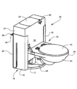
provide a safe
and easy-to-use way for these individuals to accomplish this essential human
function.
SUMMARY
[0005] Therefore, some of the objects of the present disclosure are to provide
a
toilet with an adjustable height and/or a toilet lift which is safe and easy
to use. For example,
in some embodiments, an adjustable height feature may be realized by an
elevation system
that uses water line pressure to perform the lifting/lowering function.
Another object of the
present disclosure is to conserve water, such as by using the same volume of
water for a
lifting function that is also used for flushing a toilet.
[0006] These and other objects may be met by the various implementations
described in the present disclosure. According to one embodiment, a toilet may
include a
base configured to be fastened to a floor. The toilet may also include a pair
of bracket panels
connected to the base, the pair of bracket panels extending upward from the
floor in a vertical
direction. Also, the toilet may include a tank housing confined between the
pair of bracket
panels and having an adjustable height above the base allowing the tank
housing to move in
the vertical direction between a raised position and a lowered position. The
toilet may further
include a bowl attached to the tank housing, the bowl configured to support
the weight of a
user.
[0007] According to another embodiment of the present disclosure, a toilet may
comprise a tank housing configured to collect water to be used during a
flushing cycle. The
toilet may also include a bowl attached to the tank housing, the bowl
configured to support
the weight of a user. Furthermore, the toilet may include a side rail assembly
including first
and second side rails, a rail pivot block attached to a back portion of the
bowl, and first and
second pivot shafts. The first and second side rails may be connected to the
rail pivot block
CA 03098863 2020-10-29
WO 2019/213424 PCT/US2019/030441
3
via the first and second pivot shafts, respectively. The first and second side
rails may be
configured to pivot with respect to the rail pivot block between a stored
position and a
support position for providing support to the user.
[0008] According to yet another embodiment, an exemplary toilet may include a
tank housing configured to collect water to be used during a flushing cycle
and a bowl
attached to the tank housing. The exemplary toilet may also include a seat
arranged on an
outer rim of the bowl, the bowl configured to support the weight of a user
seated on the seat.
Furthermore, the exemplary toilet may include one or more sensors configured
to sense at
least one characteristic of the user.
BRIEF DESCRIPTION OF THE DRAWINGS
[0009] The embodiments of the present disclosure may be best understood by
reference to the following description taken in conjunction with the
accompanying drawing
figures.
[0010] FIG. 1 is a perspective view of an adjustable toilet shown in a lowered
position, according to one implementation of the present disclosure.
[0011] FIG. 2 is a perspective view of the adjustable toilet of FIG. 1 shown
in a
raised position.
[0012] FIG. 3 is a perspective view of the adjustable toilet of FIG. 1 showing
details
of portions of a height adjustment system, according to one implementation of
the present
disclosure.
[0013] FIG. 4 is a perspective view of the adjustable toilet of FIG. 1 showing
additional details of the height adjustment system, according to one
implementation of the
present disclosure.
[0014] FIG. 5 is a perspective rear-side view showing fluid piping of the
adjustable
toilet of FIG. 1, according to one implementation of the present disclosure.
CA 03098863 2020-10-29
WO 2019/213424 PCT/US2019/030441
4
[0015] FIG. 6 is a diagram showing the fluidic connections of the adjustable
toilet
of FIG. 1, according to one implementation.
[0016] FIG. 7 is a perspective view of a height adjustment controller of the
adjustable toilet of FIG. 1, according to one implementation.
[0017] FIG. 8 is an exploded view of an automatic flushing and height
adjustment
system of the adjustable toilet of FIG. 1, according to one implementation.
[0018] FIG. 9 is a perspective view of the automatic flushing and height
adjustment
system of FIG. 8.
[0019] FIGS. 10A through 10C are cross-sectional views of a flushing mechanism
shown in sequential modes of operation, according to one implementation.
[0020] FIG. 11 is a cutaway, perspective view of a collapsible drainage pipe
of the
adjustable toilet of FIG. 1 shown in its fully collapsed state, according to
one implementation.
[0021] FIG. 12 is a cutaway, perspective view of the collapsible drainage pipe
of
FIG. 11 in its extended state.
[0022] FIG. 13 is a cross-sectional view of the collapsible drainage pipe of
FIG. 11
shown mounted to a toilet and drainage system, according to one
implementation.
[0023] FIG. 14 is a perspective view of an adjustable toilet lift, according
to a first
implementation.
[0024] FIG. 15 is a perspective view of an adjustable toilet lift, according
to a
second implementation.
[0025] FIG. 16 is a perspective view of an adjustable toilet lift, according
to a third
implementation.
[0026] FIG. 17 is a perspective view of an adjustable toilet lift, according
to a
fourth implementation.
[0027] FIG. 18 is a cutaway perspective view of an adjustable toilet lift,
according
to a fifth implementation.
CA 03098863 2020-10-29
WO 2019/213424 PCT/US2019/030441
[0028] FIG. 19 is a perspective view of a side rail system mounted to the
adjustable
toilet of FIG. 1, according to one implementation.
[0029] FIG. 20 is a perspective view of the side rail system of FIG. 19 shown
in a
raised or stored position.
[0030] FIG. 21 is an exploded view of the side rail system of FIG. 19.
[0031] FIG. 22 is a perspective view showing the range of motion of the side
rail
system of FIG. 19.
[0032] FIG. 23 is a perspective view of a toilet having a bedpan sprayer
system and
a foot pedal. according to various implementations of the present disclosure.
[0033] FIG. 24 is a perspective view of the toilet of FIG. 23 shown with the
foot
pedal in a lifted state.
[0034] FIG. 25 is a perspective rear-side view of the toilet of FIG. 23 having
a wall-
oriented drainage system, according to one implementation.
[0035] FIG. 26 is a perspective view of a portion of a toilet having a night
light and
automatic air freshener, according to various implementations.
[0036] FIG. 27 is a block diagram illustrating a control circuit for
controlling the
operation of a toilet, according to various implementations.
[0037] FIG. 28 is a block diagram illustrating the input devices shown in FIG.
27,
according to various implementations.
[0038] FIG. 29 is a block diagram illustrating the output devices shown in
FIG. 27,
according to various implementations.
[0039] FIG. 30 is a block diagram illustrating the mechanical actuators shown
in
FIG. 29, according to various implementations.
[0040] FIG. 31 is a block diagram illustrating software modules of the toilet
operation software shown in FIG. 27, according to various implementations.
CA 03098863 2020-10-29
WO 2019/213424 PCT/US2019/030441
6
DETAILED DESCRIPTION
[0041] The embodiments of toilets described in the present disclosure may be
installed in residential or hospital settings and are configured to assist
people with physical
disabilities or limitations in the regular human necessity of using a toilet.
Some embodiments
may include systems for adjusting a height of a toilet seat to accommodate a
user in the
process of getting onto or getting off of the toilet seat. A complementary
feature to the height
adjustment system is a collapsible drainage system and various lift systems.
[0042] Other embodiments of toilets may include sensors used with a toilet for
detecting characteristics of a user, such as body temperature, heart rate,
heart rhythm, etc.
The sensors may include cameras for detecting features of the user or features
of the waste
product. Also, a seating grid sensor may be used for calculating a user's
range of motion. In
addition, an electronic dipstick may be incorporated in the toilet for
allowing a urine test to
be performed.
[0043] Still other embodiments include accessories that may be incorporated
into a
toilet for assisting people with disabilities and/or for allowing certain
functions that may be
desirable in this environment. For example, one additional accessory may
include an
automatic flushing and/or automatic height adjustment feature. Another
accessory may
include a self-releasing flushing feature to allow a flapper to fall back into
place after the
toilet has been flushed. Another accessory includes side rails that a user can
handle for
support when getting onto or off of the toilet seat. Other features include
bedpan sprayer
devices, foot pedals for controlling aspects of the toilet, a night light, an
automated air
freshener, etc.
[0044] FIG. 1 is a perspective view of an embodiment of an adjustable toilet
10
shown in a lowered position and FIG. 2 is a perspective view of the adjustable
toilet 10
shown in a raised position. The adjustable toilet 10 includes a toilet base 12
fastened to the
floor (not shown) and an upwardly-extending skirt 14 constructed of a pair of
opposed,
CA 03098863 2020-10-29
WO 2019/213424 PCT/US2019/030441
7
generally C-shaped panels 16, or bracket panels. The toilet base 12 carries a
toilet housing 18
which includes a toilet bowl 20 and a tank housing 22. The tank housing 22 is
received in
and located by the skirt 14 between the panels 16 such that it can move freely
up and down.
The tank housing 22 includes a water tank 23 (shown in FIG. 5), a tank cover
24 on top, and
a flush handle 26 for manual flush initiation. The complete toilet housing 18
can be moved
between a lowered position (FIG. 1) and a raised position (FIG. 2). A
collapsible drainage
pipe assembly 28, as shown in detail in FIGS. 11-13, interconnects the toilet
housing 18 and
the toilet base 12.
[0045] FIGS. 3-4 are perspective views of the adjustable toilet 10 showing an
embodiment of a height adjustment system. The height adjustment system
includes one or
more lifting cylinders 30, which may be pressurized by a fluid as described
below to raise the
toilet housing 18. Gravitational force may be used to exhaust the liquid from
the lifting
cylinders 30. Two pairs of lifting cylinders 30 each contain cylinders having
a diameter of
about 10 cm (4 inches). The pairs of lifting cylinders 30 may be used for
lifting the toilet
bowl 20 through a total stroke of about 38 cm (15 inches). Other types of
lifting devices,
such as pneumatic cylinders or mechanical actuators, may be substituted for
the lifting
cylinders 30 if desired.
[0046] FIG. 3 shows how the bottom position of the toilet housing 18 can be
adjusted. An internally-threaded, square-section bottom stop bar 66 and a stop
screw 68 are
mounted in the tank housing 22. The bottom stop bar 66 can slide in a vertical
direction in
the tank housing 22. The rotatable stop screw 68 of the bottom stop bar 66 is
moved up or
down. The bottom stop bar 66 will contact the toilet base 12 in the desired
portion and stop
any further lowering of the toilet housing 18. FIGS. 3 and 4 further show the
first and second
fluid lifting cylinders 30, wherein the first fluid lifting cylinder has a
first rigid cylinder
portion 31A and a second rigid cylinder portion 31B and the second fluid
lifting cylinder has
a first rigid cylinder portion 33A and a second rigid cylinder portion 33B.
CA 03098863 2020-10-29
WO 2019/213424
PCT/US2019/030441
8
[0047] FIG. 4 illustrates how the upward stroke of the toilet housing 18 may
be
stopped. A top stop bar 72 is firmly held in the toilet base 12 and extends
into a hole 74 in
the tank housing 22. The top stop bar 72 has an enlarged top end 76 (larger
than a reduced-
diameter bottom flange of the hole 74) which interferes with further upwards
motion once it
contacts the bottom flange. The length of the top stop bar 72 may be
adjustable. A plug 78
covers the hole 74 on top.
[0048] FIG. 5 is a perspective back side view showing an embodiment of fluid
piping that may be used with the adjustable toilet 10. FIG. 6 is a diagram
showing the fluidic
connections of the adjustable toilet 10. FIGS. 5 and 6 illustrate the
structure of the raising
and lowering system of the adjustable toilet 10. Fluid (typically domestic
water supply)
enters the system from wall outlet 38 through the shut-off valve 40. It is
piped through the
flexible connector hose 42 and valve supply pipe 112 to the lift valve 90. It
also flows
through the valve supply pipe 112 to a standard filler valve 114, which is
operated by a float
116 in the water tank 23. An overflow tube 118 of a standard type has one end
disposed in
the water tank 23. The water tank 23 may be an integral part of the tank
housing 22.
[0049] A cylinder supply line 120 extends between the lift valve 90 and the
lifting
cylinders 30, and may include a raising throttle 122 therein (e.g. a fixed or
variable orifice)
for controlling the speed of the raising motion. As shown, the lifting
cylinders 30 may also
be integrally-formed with the tank housing 22. A recycling line 124 connects
to lift valve 90
to the water tank 23. A lowering throttle 126 in the recycling line 124,
similar to the raising
throttle 122, enables control of the descending speed of the toilet bowl 20.
The drain valve
100 is connected to the lift valve 90 on one side and to the cylinder supply
line 120 on the
other side to enable automatic resetting of the toilet bowl 20 when the lid 36
is closed.
[0050] Manual lifting and lowering of the toilet housing 18 operates as
follows. To
raise the toilet housing 18, the height adjustment lever 32 is raised, causing
pressurized water
to flow into the lifting cylinders 30. To lower the toilet housing 18, the
height adjustment
CA 03098863 2020-10-29
WO 2019/213424 PCT/US2019/030441
9
lever 32 is lowered, allowing water to be forced out of the lifting cylinders
30 and through the
recycling line 124 into the water tank 23. To the extent that raising and
lowering the toilet
housing 18 without flushing causes the water tank 23 to approach an overfilled
condition, the
excess water drains through the overflow tube 118.
[0051] A height adjustment lever 32 is also incorporated into the tank housing
22
and serves as the control for raising or lowering the toilet housing 18. A
seat 34 and lid 36
are mounted on top of the toilet bowl 20. A water supply is fed to the
adjustable toilet 10
through a wall outlet 38, for example using a shut-off valve 40 feeding a
flexible connector
hose 42.
[0052] FIG. 7 is a perspective view illustrating an embodiment of a height
adjustment controller that may be used with the adjustable toilet of FIG. 1 or
other toilet
having an adjustable height. The height adjustment controller includes linkage
for raising
and lowering the toilet bowl 20. It includes the height adjustment lever 32
with pivot shaft 80
and extension lever 82 connected thereto. A pivot plate 84 is mounted on the
tank housing 22
using mounting holes 86 and allows the height adjustment lever 32 to pivot. An
actuating rod
88 of a lift valve 90 is connected to the extension lever 82. Moving the
height adjustment
lever 32 up or down moves the actuating rod 88 out of or into the lift valve
90. In this
example, the lift valve 90 may be a 3-way valve of a type that is manually
operated. The lift
valve 90 may have three positions and may be spring-centered.
[0053] FIG. 8 shows an exploded view of an embodiment of an automatic flushing
and height adjustment system of the adjustable toilet of FIG. 1. Also, FIG. 9
is a perspective
view of the automatic flushing and height adjustment system of FIG. 8. The
automatic
flushing and height adjustment system shown in FIGS. 8 and 9 is capable of
automatically
resetting the toilet to a predetermined height while simultaneously performing
an automatic
flushing action. An automatic resetting pin 92 is positioned under one of the
mounts 94 of
the lid 36, and is connected to the front end of a pivot link 96, the rear end
of which is
CA 03098863 2020-10-29
WO 2019/213424 PCT/US2019/030441
connected to the actuating rod 98 of a drain valve 100. In this example, the
drain valve 100 is
a normally-closed, manually-operated and spring-biased 2-way valve. The rear
end of the
pivot link 96 is connected to an upright flushing rod 102 which in turn is
connected to a
conventional flapper valve 104 by a flapper chain 106. The flapper valve 104
is pivotally
held by a flapper pivot 108. The flush handle 26 is pivotally mounted to the
tank housing 22
and connected to the flushing rod 102 by a lever extension 110. Thus, the
toilet may be
flushed automatically by closing the lid 36 or by pressing the flush handle
26.
[0054] If desired, the adjustable toilet 10 may be flushed by pushing the
flush
handle 26 down in a clockwise motion. This raises the lever extension 110
which is
positioned under the flushing rod 102. This motion will cause the flapper
chain 106 to open
the flapper valve 104 in order to flush the toilet, in a conventional manner.
[0055] The automatic resetting of the toilet height adjustment and
simultaneous
automatic flushing features operates as follows. Lowering the lid 36 will
depress the
automatic resetting pin 92, which in turn rotates pivot link 96 clockwise.
This will raise the
actuating rod 98 of the drain valve 100, opening the drain valve 100 to
release the liquid out
of the lifting cylinders 30 through the recycling line 124, and allowing the
tank housing 22 to
lower to its bottom position.
[0056] FIGS. 10A - 10C show cross-sectional views of an embodiment of a
flushing mechanism. The flushing mechanism of FIGS. 10A - 10C is shown in
sequence
throughout a flushing cycle. For example, FIG. 10A shows an initial state in
which water is
allowed to collect within the water tank 23 as the flapper valve 104 remains
closed. FIG.
10B shows an initial flush action where the resetting pin 92 (see FIGS. 7-8)
is compressed by
the closing of the lid 36 or the flush handle 26 is pressed. FIG. 10C shows a
releasing action
that allows the flapper valve 104 to close when the lid 36 remains closed.
[0057] Simultaneously, the pivot link 96 lifts the flushing rod 102 and
flapper chain
106, opening the flapper valve 104 to initiate a flush cycle. When the
flushing rod 102 is
CA 03098863 2020-10-29
WO 2019/213424 PCT/US2019/030441
11
initially raised (FIG. 10A), the spring latch 102C maintains the upper and
lower portions
102A and 102B extended at their full length. As the flushing rod 102 is raised
further, the
spring latch 102C is depressed by contact with the tapered section 103A of the
channel 103,
shown in FIG. 10B, allowing the upper portion 102A to collapse into the lower
portion 102B,
as shown in FIG. 10C. This allows the flapper valve 104 to close normally.
When the pivot
link 96 is lowered again, the flushing rod 102 extends to its full length and
the spring latch
102C resets. Thus, the act of closing the lid 36 both empties the toilet 10
and resets its height
for the next user. The space vacated in the water tank 23 as the flush cycle
occurs provides
room to receive the water drained from the lifting cylinders 30. The automatic
lowering
feature and/or the automatic flushing feature may be implemented together as
described
herein, separately, or not at all.
[0058] The amount of water to be used for a full lift of about 38 cm (15
inches) is
about 6 liters (1.6 gallons). This amount of fluid is released into the water
tank 23 and will
be used for the next flushing. In this manner, the water for the lifting
action is not wasted (i.e.
drained through the overflow tube 118) but is preserved, and is the same
amount as is legally
required at this time to be the maximum to be used for one flushing. It is
also noted that the
use of two lifting cylinders 30 of approximately 10 cm (4 in.) diameter
results in a total lifting
force of about 227 kg (500 lbs.) at a nominal water pressure of about (20
psi). In the unlikely
case that the line water pressure does not suffice, a booster pump of known
type can be
inserted between the water line and the system of the adjustable toilet.
[0059] The flushing rod 102 includes means for allowing the flapper valve 104
to
return to a closed position after the flush cycle is completed. In the example
illustrated in
FIGS. 10A-10C, the flushing rod 102 comprises an upper portion 102A received
inside a
tubular lower portion 102B. The upper portion 102A carries a laterally-
moveable spring
latch 102C at its lower end. The flushing rod 102 is carried in a vertical
hole or channel 103
CA 03098863 2020-10-29
WO 2019/213424 PCT/US2019/030441
12
in the tank housing 22 which includes a tapered section 103A connecting a
lower section
103B and a narrower upper section 103C.
[0060] The flushing mechanism shown in FIGS. 10A-10C may include the flushing
rod 102, the channel 103, and a flush tube (i.e., the tubular lower portion
102B) that may be
lifted by the pivoting action of the pivot link 96. The flushing rod 102 may
be attached to a
flapper (i.e., flapper valve 104) configured to seal an opening in a bottom
portion of the tank
housing 22. The flushing rod 102 may include a reduced-diameter section that
engages with
the spring latch 102C. The spring latch 102C has a shoulder and a forked
portion. The flush
tube 102 is configured to move in an upward direction during a flushing
process (FIG. 10B)
causing the flush rod 102 to lift the flapper 104 from the opening to allow
water to escape
from the tank housing 22.
[0061] When moved in the upward direction. the top end of the flush tube 102B
contacts a bottom surface of the shoulder of the spring latch 102C to lift the
spring latch
102C until it intersects the tapered section 103A. With continued upward
movement, the
forked portion of the spring latch 102C is forced toward a central axis of the
flushing rod 102.
When the forked portion moves enough toward the central axis of the flushing
rod 102, the
shoulder of the spring latch 102C moves within an interior diameter of the
flush tube and then
drops down into the interior of the flush tube 102B as shown in FIG. 10C. This
dropping
movement causes the flushing rod 102 to drop within the tank housing 22 to
allow the flapper
104 to also drop down into the opening of the tank housing 22 to seal the
opening.
[0062] FIG. 11 shows a cutaway, perspective view of an embodiment of the
collapsible drainage pipe 28 of the adjustable toilet 10. FIG. 12 shows
another cutaway,
perspective view of the collapsible drainage pipe 28. FIG. 11 shows the
collapsible drainage
pipe 28 in its fully collapsed state and FIG. 12 shows it in its extended
state. Furthermore.
FIG. 13 shows a cross-sectional view of the collapsible drainage pipe 28'
mounted to a toilet
and to a drainage system, the collapsible drainage pipe 28 shown in its
collapsed state.
CA 03098863 2020-10-29
WO 2019/213424 PCT/US2019/030441
13
[0063] The drainage pipe assembly 28, 28 is made up from several closely-
fitted
concentric pipe segments 60, with their diameter decreasing from the bottom of
the assembly
28, 28' to its top. Each pipe segment 60 has an outwardly-extending flange 62
at its lower
end and a resilient ring 64 at its upper end to provide a seal against leakage
of waste, odor,
and liquid. In FIG. 11, the drainage pipe assembly 28 is collapsed as is the
case with the
toilet bowl 20 in its lowest position. In FIG. 12 the drainage pipe assembly
28 is extended as
is the case with the toilet bowl 20 in its highest position. The ever
increasing diameter from
the top segment 60 to the bottom segment 60 prevents the drainage pipe
assembly 28, 28'
from presenting a "shelf' which could collect waste. The lowering and raising
of the toilet
bowl 20 will have a scrubbing action on the side walls of the drainage pipe
assembly 28, 28'
and drop the scrubbed off particles effectively down a drainage hole in the
floor.
[0064] As shown in FIG. 13, the toilet base 12 may be provided with a pipe
stub or
"horn" 700 and mounting bolt holes 702 which allow it to be mounted to a
standard plumbing
toilet flange 704 and drain pipe 706. To accommodate this mounting, an
alternative drain
pipe assembly 28' may be used which has a tapered bottom pipe segment 60' to
make a
smooth transition to the diameter of the horn 700.
[0065] FIGS. 14-18 show perspective views of various embodiments of adjustable
toilet lifts. These lifts may be used with the toilet 10 described above or
with an existing
toilet.
[0066] A first exemplary adjustable toilet lift 210 is illustrated in FIG. 14.
The
toilet lift 210 includes a base plate 212 and a top plate 214, and one or more
actuators 222 for
moving the top plate 214 relative to the base plate 212, which are pivotally
connected
hydraulic jacks in the illustrated example. The top plate 214, which carries a
standard toilet
(not shown), includes three flange members 224 extending upward and having
horizontal
members 226 at the upper ends thereof, which engage the actuators 222.
CA 03098863 2020-10-29
WO 2019/213424 PCT/US2019/030441
14
[0067] Two aligned bores 216, 218 are positioned within the base plate 212 and
top
plate 214, respectively, to allow discharge from the toilet to pass through
the lift 210 by way
of a drain extension 220. The bore 216 of the base plate 212 is connected to
the drain
opening in the floor, and the bore 218 of the top plate 214 is connected to
the drain outlet of
the toilet. An external power source (not shown) such as a hydraulic pump is
employed to
selectively raise and lower the actuators 222.
[0068] FIG. 15 shows a second adjustable toilet lift 310 in which the actuator
comprises one or more scissor frame jacks 328 positioned between a base plate
312 and a top
plate 314. The jacks 328 each include a threaded screw 322 extending laterally
therethrough
with an optional turning knob 332 positioned on one end. As the screw 322 is
turned in one
direction, frame hinges 324 move along the threads of the screw 322 toward
each other,
causing the jacks 328 to extend upward. When the screw 322 is turned in the
opposite
direction, the frame hinges 324 move away from each other, causing the jacks
328 to collapse
downward. Two aligned bores 316, 318 are positioned within the base plate 312
and top
plate 314, respectively, which allow discharge from the toilet to pass through
the lift 310 by
way of a drain extension (not shown). Preferably, the top plate 314 includes a
lowered
channel 330 for receiving a toilet and providing added stability. An external
power source
(not shown) can be employed to rotate the screw 322. In the alternative, the
knob 332 can be
turned manually.
[0069] FIG. 16 shows a third adjustable toilet lift 410 in which an X-frame,
located
between a base plate 412 and a top plate 414, comprises a first pair of rods
436A, 438A and a
second pair of rods 436B, 438B. The pairs are identical and only 436A and 438A
are
described in detail. The rods 436A, 438A are arranged in a crisscross fashion
and pivotally
connected by a pin 439. One end of rod 436A is pivotally connected to the base
plate 412,
while the other end, which carries a rolling wheel 440, contacts the underside
of the top plate
414. One end of rod 438A is pivotally connected to the underside of the top
plate 414, while
CA 03098863 2020-10-29
WO 2019/213424 PCT/US2019/030441
the other end, which carries a rolling wheel 440', contacts the base plate
412. An adjusting
frame 442 is connected to rod 438A in close proximity to the rolling wheel
440'. The
adjusting frame 442 comprises a rod arrangement that is connected to and
driven by an
actuator, such as the illustrated gas spring 422.
[0070] Movement of the gas spring 422 moves the adjusting frame 442, which in
turn drives the rolling wheel 440 in a horizontal direction to move the top
plate 414 relative
to the base plate 412. Two centrally located bores 416, 418 are positioned
within the base
plate 412 and top plate 414, respectively, which allow discharge from the
toilet to pass
through the lift 410 by way of a drain extension (not shown).
[0071] FIG. 17 shows a fourth adjustable toilet lift 510 that employs a
plurality of
actuators 522 which are pivotally connected to both the base plate 512 and top
plate 514. The
actuators 522 are arranged in a crisscross arrangement. Extension or
retraction of the
actuators 522 raises or lowers the top plate 514 respectively, while the
crisscross
configuration provides stability to the top plate 514. The actuators 522 may
be any device
capable of raising the top plate 514 under a load, such as screw jacks,
pneumatic jacks, or
spring lifts. In the illustrated example, the actuators 522 are gas springs. A
flexible,
extendible drain extension 520 extends between bores 516, 518 located in the
base plate 512
and top plate 514, respectively.
[0072] FIG. 18 shows a fifth adjustable toilet lift 610 comprising a base
plate 612
having spaced-apart side portions 648 and spaced-apart end walls 649, which
extend
upwardly to collectively form a cavity 650 therein. An open-ended chamber 658
is located
within each of the side portions 648 and houses an actuator for adjusting a
top plate 614
relative to the bottom plate 612, which is a gas spring 622 in the illustrated
example. A top
plate 614 defines two upwardly extending side members 654, including outwardly
extending
flange members 656 at the upper ends thereof. The side members 654 are
connected to the
distal ends of the gas springs 622 which protrude through the open end of the
chambers 658.
CA 03098863 2020-10-29
WO 2019/213424 PCT/US2019/030441
16
Two centrally located bores 616. 618 are positioned within the base plate 612
and top plate
614, respectively, to allow discharge from a toilet to pass through the lift
610 by way of a
drain extension (not shown). The cavity 650 of this embodiment provides the
added benefit
of increased support to the base of the toilet, which prevents bending
moments. In addition,
the side portions 648 provide a decorative touch that is more aesthetically
pleasing to a
consumer and protect the gas springs 622.
[0073] The lifts as described herein with respect to FIGS. 14-18 allow an
individual
to preset the required height of the toilet before use. After the user is
seated upon the seat of
the toilet, the height can be further adjusted to accommodate the requirements
and desires of
the user. After use, the height can be adjusted again to allow users to safely
remove
themselves from the seat. The adjustment of the height can be accomplished by
way of an
external power source before, during, and after use.
[0074] The lifts illustrated in FIGS. 14-18 can be integral to a toilet or
separately
installed on an existing toilet. During installation, the base plate of the
toilet lift is secured to
a common household drain using a wax seal of a known type, and securely
connected to the
floor using screws, fasteners, or the like. For integral units, the top plate
would be integrally
formed with the base portion of a toilet. For units which are attached to an
existing toilet, the
top plate is welded, glued, fastened, anchored, bolted, or screwed to the
bottom of the toilet,
with the drain outlet of the toilet placed over the bore of the top plate and
connected to the
drain extension. A wax seal may be installed between the top plate and the
bottom of the
toilet in this application to ensure no leakage occurs.
[0075] FIG. 19 is a perspective view of an embodiment of a side rail system
mounted to a toilet, and in some implementations may be mounted to the
adjustable toilet 10
of FIG. 1. In addition, FIG. 20 is a perspective view of the side rail system
shown in a raised
or stored position. FIG. 21 is an exploded view of the side rail system and
FIG. 22 is a
perspective view showing the range of motion of the side rail system.
CA 03098863 2020-10-29
WO 2019/213424 PCT/US2019/030441
17
[0076] The side rails 44 of the side rail system may be used for supporting a
user
and can assist the user while getting onto or off of the seat 34. In FIG. 19,
the side rails 44
are shown in a lowered or operating position. The side rails 44 bear on the
toilet bowl 20
with attached rail plates 46. In FIG. 20, the side rails 44 are shown in a
raised or retracted
position. The side rails 44 are pivotally mounted in a rail pivot block 48,
which in turn is
mounted onto the toilet housing 18.
[0077] A pair of rail pivot shafts 50, the rail pivot block 48, and centering
pins 52
are shown in FIG. 21. Centerlines indicate how the different parts are fitted
together. Each
side rail 44 can be raised or lowered independently by pivoting with its rail
pivot shaft 50,
and can be slid inward or outward along its rail pivot shaft 50, to facilitate
mounting and
dismounting of the toilet 10. Spring-loaded ball plungers 54 mounted in the
rail pivot shafts
50 serve to lock the side rails 44 to the desired width, in cooperation with
holes 56 in the side
rails 44. It is understood that other common fastening methods can be used for
permanent or
temporary locking the side rails 44 onto rail pivot shafts 50. A slot 58 in
the pivot block 48
receives the centering pins 52 to assure that the side rails 44 are held in
place in the pivot
block 48.
[0078] FIG. 22 shows how the parts fit together and how a user can select
appropriate holes 56 in the side rails 44 for adjusting the side rails 44 to a
desired width. The
dotted lines show the outermost positions of the side rails 44 as well as
their up and down
positioning.
[0079] FIG. 23 is a perspective view of a toilet showing various embodiments
of a
bedpan sprayer system 800, a foot lift 810, and a foot pedal 812. As shown in
FIG. 23, the
the foot lift 810 is in a flat position against the floor. FIG. 24 is a
perspective view of the
toilet of FIG. 23 shown with the foot lift 810 in an elevated state. The foot
lift 810 may
include hinged platforms that are controlled to position the platforms in the
flat position or
the elevated position.
CA 03098863 2020-10-29
WO 2019/213424 PCT/US2019/030441
18
[0080] In some embodiments. the positioning of the platforms of the foot lift
810
may be controlled by pressing the foot pedal 812. According to other
embodiments, the foot
pedal 812 may be used to actuate one or more other functions, such as raising
or lowering the
height level of the seat 34. The foot pedal 812 may also be used to
automatically flush the
toilet, reset the height of the seat 34 to a predetermined level,
automatically close the lid 36,
and/or other functions. In still other alternatives, the toilet may include
one or more
additional actuators 814 for controlling one or more of these various
functions.
[0081] The toilet may use an actuator (e.g., pedal 812, actuators 814, etc.)
requiring
an external power source (e.g., electric, air, or hydraulic motor) connected
to the actuator.
Other types of actuation may include a wall-mounted joy stick or other similar
control
mechanism. The user is able to operate the external power source using the
controller to
adjust the toilet to the desired height and/or to perform other functions.
[0082] In some embodiments, the actuators 814 may be implemented as sensors
for
sensing various parameters. For example, a toilet function may be controlled
remotely by a
motion sensor 814 disposed near a toilet and interconnected to a centrally
located server,
which may in turn be connected to an external power source. The centrally
located server
includes a preset initial height stored therein. When the motion sensor 814 is
activated by an
individual approaching the toilet, the server automatically activates the
external power source
to adjust the toilet to the preset initial height.
[0083] FIG. 25 is a perspective rear-side view of the toilet of FIG. 23 having
a wall-
oriented drainage system. For example, the toilet may include a flange mount
toilet horn 820
for connection with the drainage system. The toilet may also include a wash
hose 822
configured to receive clean water from a water supply. The wash hose 822 may
be used for
cleaning body parts of the user and/or for cleaning the toilet itself or the
floor surfaces around
the toilet.
CA 03098863 2020-10-29
WO 2019/213424 PCT/US2019/030441
19
[0084] FIG. 26 is a perspective view of a portion of a toilet having a night
light 826
and automatic air freshener 828, according to various implementations. The
night light 826
may be connected to an electrical power source to allow the user to be able to
use the toilet at
night or when the bathroom is dark. The automatic air freshener 828 may be
configured to
automatically spray a mist of air freshening solution into the air when the
toilet is flushed,
when the toilet detects that the user has sat down on the seat 34, and/or at
other times when
air freshening may be needed.
[0085] According to additional embodiments of the present disclosure, the
toilets
described above may include any combination of electrical circuits for sensing
parameters,
capturing images, communicating electrical signals related to sensor data,
transmitting signals
to routers or other electrical terminals by Wi-Fi connectivity, communicating
with remote
servers via the Internet or over other networks, and other electric
capabilities. Thus, the
toilets may be provided with sensors (e.g., proximity sensors), cameras,
infrared cameras,
Internet connection devices, Wi-Fi equipment, voice recognition sensors,
and/or other
electrical circuitry for performing, assisting, or prompting the functions
described in the
present disclosure. As an example, a camera may be used to capture facial
features of a user,
whereby facial recognition software may be used to determine the identity of
the user and
actuate an automatic height adjustment function for that particular user.
According to another
example, a proximity sensor may detect when a user has moved off the seat 34
and may then
prompt an automatic flushing action.
[0086] FIG. 27 is a block diagram illustrating an embodiment of a control
circuit
900 for controlling the operation of a toilet, such as the toilet 10 of FIG. 1
and/or the toilet
shown in FIG. 23. The control circuit 900 includes one or more processors 902
and a power
source 904 that provides power to the processors 902 and other components of
the control
circuit 900. The control circuit 900 further includes input devices 906 and
output devices 908.
Also, the control circuit 900 includes a memory 910 and one or more network
interfaces 912
CA 03098863 2020-10-29
WO 2019/213424 PCT/US2019/030441
for connections with external networks (e.g., the Internet, cellular networks,
etc.). The
memory 910 may be configured to store toilet operation software 914 for
controlling the
operations of the toilet.
[0087] FIG. 28 is a block diagram illustrating embodiments of the input
devices 906
shown in FIG. 27. For example, the input devices 906 may include one or more
of the
devices shown in FIG. 28 and/or other similar devices for receiving input
signals that can be
processed by the processors 902 to control various aspects of the toilet. As
illustrated in FIG.
28, the input devices 906 may include proximity sensors 916, motion sensors
918, user
interfaces 920, microphones 922, cameras 924, infrared (IR) cameras 926,
electronic scales
928, thermal imaging devices 930, heart rate monitors 932, and waste sensors
934.
[0088] FIG. 29 is a block diagram illustrating embodiments of the output
devices
908 shown in FIG. 27. According to various implementations, the output devices
908 may
include one or more of mechanical actuators 938, audible devices 940, visual
devices 942,
mobile devices (e.g., smart phone applications) 944, and/or others.
[0089] FIG. 30 is a block diagram illustrating embodiments of the mechanical
actuators 938 shown in FIG. 29. For example, the mechanical actuators 938 may
include
automatic flushing actuators 948, height adjustment actuators 950, seat
adjustment actuators
952, and rail adjustment actuators 954. and/or other actuators.
[0090] FIG. 31 is a block diagram illustrating embodiments of various software
modules of the toilet operation software 914 shown in FIG. 27. For example,
according to
some embodiments, the software modules toilet operation software 914 may
include voice
recognition 960, facial/eye recognition 962, identity detection 964. automatic
height
adjustment 966, automatic flushing 968, body mass/weight/height measurement
970, and
hear rate monitor 972. Other software modules may include body temperatures
measurement
974, alert handling 976, body scan 978, pathology/waste analysis 980, sensor
activation 982,
notification 984, range of motion detection 986, and medication
reminder/prescription refill
CA 03098863 2020-10-29
WO 2019/213424 PCT/US2019/030441
21
988. Any one or more of the software modules shown in FIG. 31 may be used
alone or in
combination with other modules to allow the processor 902 to perform various
toilet control
actions as described above.
[0091] There can be a multitude of sensors 906 used that may include different
functions. Motion sensors 918, Wi-Fi devices 912, and cameras 924 with
infrared
capabilities 926 can be integrated into the sensors. These devices 906 may
have their own
power source 904 and may also have a manual override system.
[0092] Thus, with various sensors 906 and one or more processing devices 902
(e.g.,
microprocessor, microcontroller, central processing unit, etc.), the toilets
described in the
present disclosure may be able to perform additional functions, such as
measure body mass
970 of the user, detect a user's height 970 and automatically adjust the
height 966 of the seat
34 according to the user's height allowing for maximum comfort and ideal body
position
whether the user is sitting or standing, utilize voice recognition software
960 to respond to
voice commands, facial recognition software 962, and even eye/iris recognition
software 962.
[0093] Some sensors 906 may include body temperature reading 930, 974 and
assessment capabilities. Other sensors may detect motion 918 or detect if a
user has fallen,
which may result in handling alerts 976 to doctors, nurses, family members,
etc., and may
include notification 984 to the user or to medical professionals as needed.
[0094] The toilets equipped with electrical circuitry (e.g., control circuit
900), as
described herein, may implement Wi-Fi capabilities of a network interface 912
to
communicate with a router or other network device to allow the use of an
application
designed for medical personnel in a hospital or other health care center
and/or for remote
special care monitoring. The toilets described herein may communicate to
medical personnel
to inform 976, 984 nurses or doctors of various conditions, such as a user who
has fallen from
the toilet. This information may also be remotely communicated to medical
personnel as
CA 03098863 2020-10-29
WO 2019/213424 PCT/US2019/030441
22
needed. Remote control of the toilet may allow activation of the water valve
systems of the
toilet to flush 968 from outside the bathroom.
[0095] In accordance with some embodiments. the toilet may be equipped with 3D
imaging. The toilet may be configured to activate the 3D imaging system using
cameras 924.
Some cameras 924 may be used to produce a hologram image 942 that will allow
one to
communicate to a visible responder.
[0096] Multiple sensors 906 may be placed at various points around the toilet
to
detect various angles of the users and/or urine and bowel movements. Because
of the
multiple placements of the sensors and the adjustability of the toilet height,
full or partial
body scans may be performed 978 as the toilet is adjusted up and down. The
user (or remote
medical staff) may request a body scan 978, such as by pressing a button 920
on the toilet,
and the body scan cameras 924 and other electrical hardware/software may
perform the scan
function 978 and provide a read out in audible 940 or visual 942 forms. In
some
embodiments, body scan information may be provided to an application on a
user's mobile
device 944 (e.g., smart phone).
[0097] Some sensors 906 may include microphones 922 (e.g., waterproof
microphones) or other audio input devices to receive voice commands. Thus,
someone may
give specific orders to the toilet, such as to operate a variety of functions,
without the need to
touch the toilet or buttons or other input components on the toilets. Audio
signals may also
be received 922 by the sensors regarding a user's desire height, and in
response the automatic
raising or lowering devices 950 may be used to adjust the height as commanded.
[0098] Voice commands 960 may also be used to adjust a four-way integrated
railing system 954 isometrically or individually (right or left side rails
44). It can adjust out
of the way of an abled body person that has no need for them or they can
adjust to the
commands of a handicap, disabled, or a recent surgery recipient, that wishes
to move the rails,
up, down, expand them out or in for their comfort, without the need to do it
manually. Voice
CA 03098863 2020-10-29
WO 2019/213424
PCT/US2019/030441
23
commands 922 may also be used to allow the user to raise or lower the toilet
seat/lid 952
hands free, to flush the toilet 948 hands free.
[0099] Audio components may be functional through a voice recognition 960
response and can be activated or shut down by voice recognition 960. In some
implementations, safety scripts may be embedded into the software 914,
including words to
avoid any perceived dangers to children, elderly, disabled, and others.
[0100] Within the application 944, there is a single switch interface that
will allow
one to build complete sentences, giving commands to a speech synthesizer
program of the
toilets. It may also be used as a benefit for those who only can use eye
movement 962 for
communication. For example, it may allow response to a first care operator by
detection of
the up, down, left, or right movement of the occupant's eyes.
[0101] It is
noted that the toilets described herein may recycle the water used for
adjusting the height to also be used for the flush. The toilets can flush
automatically 948 and
reset themselves to the original starting height 950 once the user puts the
toilet lid/seat in the
down position (manually). Therefore, the command to put the toilet lid/seat
down will
automatically reset the toilet to its original height 950 and recycle the
water for the flush, and
then will flush automatically 948. Hence, the systems may operate multiple
functions with a
single command.
[0102] Cameras 924 may also be incorporated in the toilets. The cameras 924
may
be activated in the case of emergencies, for first response officers. Sensors
906 may detect if
the person has transferred to a chair, stood up, or fallen off of the toilet.
lf the occupant has
fallen off of the toilet, the cameras 924 and microphones 922 will activate
automatically to a
first response officer. This will allow the officer to have hands free
communication to the
occupant, and get help to the occupant as quickly as possible.
[0103] The toilets may use infrared 926, thermal imaging 930, and/or Automatic
Temperature Compensator (ATC) capabilities to detect body temperature 974 that
could
CA 03098863 2020-10-29
WO 2019/213424 PCT/US2019/030441
24
indicate numerous physical conditions, such as fever, swine flu (H1N1), the
SARS epidemic,
or other ailments. Because the processor 902 may integrate signals to or from
the sensors
906, cameras 924, and Wi-Fi devices 912, doctors or medical staff may be
notified from the
toilet or from a first responder, either in a hospital or at home, for
receiving accurate
notifications of the user's condition, such as a significant change in body
temperature.
[0104] Not only will a fall activate 982 the toilet camera, it will also
activate one or
more of a set of preset cameras through the application on the mobile device
944 (e.g., smart
phone, tablet, camera, etc.), while sending out notifications 984 to anyone,
such as family or
medical professionals. There will also be a video screen 942 activated on the
toilet, the
screen 942 will be embedded into the toilet's structure behind a clear coat or
other protective
surface, similar to the way a television may be embedded behind a mirror. The
television
screen can also be detachable, the screen size may vary, and it may have touch
screen 920
technology compatible with any camera 924 linked to it. This will allow for
use in safe
rooms or storm bunkers.
[0105] According to yet another implementation, the toilets described herein
may
further use a varied external power source 904, such as fuel cell technology
that allows the
toilet to convert chemical/liquid energy (such as water) from a fuel into
electricity through a
chemical reaction of positively charged hydrogen ions with oxygen or another
oxidizing
agent. Other types of fuel cells can also be integrated into the toilets
described herein. This
will also allow for operation with use of minimum water in any location where
there may be
no electricity, such as outer space. Zero gravity energy can also be used as
an external power
source 904, along with battery, electrical outlet and cord. Any of these
sources can be
combined into one toilet system.
[0106] The power source 904 may be located in the toilet housing 18 and toilet
bowl 20, and may be attached to the side rails 44 to the toilet. The toilet
block or toilet
housing, regardless of its material, can be a housing unit for the power
source 904, even if the
CA 03098863 2020-10-29
WO 2019/213424 PCT/US2019/030441
side rails 44 are not inserted into the block. The rails 44 can be installed
at any time and will
be activated when installed with the block, with infrared technology, and or
any desirable
power source.
[0107] The application software 914 configured to operate on a mobile device
944
(e.g., smart phone, tablet, etc.) may be designed to assist the medical
professionals and the
user/patient. All functions on the toilets can be operated from the
application 914, which
may include the capability of automatically texting 976, 984 regarding the
location of the
toilet or bathroom for those that are deaf or hearing impaired. Also, the
application 914 may
automatically send a voice message 940 regarding the location.
[0108] The toilet may also include an anatomically correct seating grid 928 to
the
toilet seat 34 that may be more comfortable for a patient who has received a
surgical
procedure to the lower back, lumbar area, hip, knee, or ankle. The toilet may
include the foot
lift 810, which may include a retractable sensor pad 928 that the user can
stand on allowing
the user to start from a standing position and then gradually lower themselves
to a position of
maximum pain tolerance. Once they have reached their maximum pain tolerance,
they can
then enter 920 the information from the seating grid 928 into the application
(app) 914, or
plug a cable from the toilet into the mobile device 944 to provide information
to the app, or
alternatively may provide information through the voice recognition software
960. The app
914 will then take all the calculations and put them into an algorithm to
determine the
patient's range of motion 986 at the time. This information may be relayed 984
to the
patient's caretaker, doctor, or nurse. This will save time on making multiple
trips to the
doctor's office to check on one's progress. With the camera functions. the
doctor will be able
to monitor the healing process.
[0109] The toilet can also be set up, such as through an app reminder system,
to
take medications 988 at specific times, such as for diabetic management,
hypertension, birth
control, thyroid issues, osteoporosis, prostate, kidney, congestive heart
failure, etc. After the
CA 03098863 2020-10-29
WO 2019/213424 PCT/US2019/030441
26
medication is taken, the user can disarm the notification until the next dose
is required, if the
dose is only to be taken for a set amount of days. The user's doctor, nurse,
or pharmacist can
set the exact amount of days on the app and notify the user to refill a
prescription 988, which
can be done securely on the app, and can be delivered directly to the user's
residence who
may be homebound. This can also save time for both the patient and the medical
professionals.
[0110] The foot lift 810 may also be configured as a scale 928 for detecting
body
mass 970. The app 914 may read the weight 970 of a user from the foot lift
scale 810 and/or
from an integrated scale 928 located in the seat 34. If a weight is measured
while the user
places their hands on the railing system, the toilet can measure a body
composition to get a
reading that indicates what the user's body may be lacking and what their body
needs. The
processor 902 may be configured to calculate body fat, body mass index, vital
signs, and
overall health and conditioning 970, 972, 974. That information may be
transferred to any
wired or wirelessly connected devices, and will allow the user to share
information with their
doctor, nurse, or caregiver.
[0111] In some embodiments, the railing system may include side rails 44 that
have
integrated sensors for testing heart rate 932. These sensors 932 may use their
own external
power system 904 and/or may connect to the toilet's power system, allowing a
fully
functional integration with the voice recognition capabilities 960, and the
application sources.
[0112] The user may also be able to adjust the toilet's height manually
through the
integrated railing system, using Wi-Fi or touch processes 920. One touch
process 920 may
include touching a top rail portion to move the toilet up, touching a bottom
rail portion to
move the toilet down, and taking hands off the rails completely to stop the
movement of the
toilet. These actions may operate on a sensor basis and may be configured to
operate if
touched on certain areas of the rails.
CA 03098863 2020-10-29
WO 2019/213424 PCT/US2019/030441
27
[0113] The rails 44 may also be configured to include electrocardiogram (EKG)
sensors 932. The processors 902 of the toilet may be configured to test and
record the heart's
electrical impulses 972 to create an electrocardiograph, a reading that helps
physicians learn
more about the heart. It uses the heart's natural electricity to record data,
so the procedure
can be done in a noninvasive manner in or outside of a hospital, clinic, or
medical setting.
[0114] At times, urine tests may be needed using waste sensors 934. In some
cases,
urine tests 980 may be performed to determine drug or alcohol measures in
legal situations.
In legal cases, a defendant may be required to take a drug and alcohol test,
or for medical
professionals to test urine or feces. This tester for sensing waste products
934 can be built
into the toilets described in the present disclosure. The tester 934 may
alternatively be
attached to an existing toilet bowl.
[0115] Urine tests 980 can be used to report a basic diagnostic to determine
pathological changes in one's urine. The test will function in the same
capacity as a urine test
strip that may comprise up to 10 different chemical pads or reagents, which
react to color
change when removed from a urine sample. However, there are ways that a person
can cheat
the test and use someone else's "clean" urine or feces as a substitute for
their own.
[0116] With the present implementations, the toilet may be configured to
prevent
fraudulent tests. For example, the toilet may determine the identity of a
person using one set
of sensors 964, while another set of sensors 934 may be used in parallel to
detect the urine
sample. In this way, the toilet can read who the subject is and receive a
sample from only
that subject. Once the subject is identified, the subject must not leave the
sensor area of the
toilet, but must sit down on the toilet. In some implementation, the subject
may further be
recorded from the back. These safe guards may be used so that the subject
cannot use
another person's urine. For example, once seated, the subject may be required
to place both
hands on the side rails 44 having identity sensors, and must stay in contact
with the rails 44
until the subject has completed urination. This method safeguards against the
subject pouring
CA 03098863 2020-10-29
WO 2019/213424 PCT/US2019/030441
28
another person's urine over a test strip into the toilet. Also, sensors may be
used to detect the
presence 916 of another person in close proximity who may be trying to alter
the test. If one
or more of these requirements is not met, the subject must re-test.
[0117] In some embodiments, the urine dipstick 934 may automatically deploy
from a back portion of the bowl 20 for a female or from a front portion of the
bowl 20 for a
male. The dipstick 934 may be situated high enough that it is not affected by
flushing. For
an electronic test strip or dipstick 934, once the test is completed, there is
no need for the
subject to do anything else. Since the test strip is electronic in this case,
it will clean itself for
the next test and retract itself back into the bowl. The strips may be
interchangeable
depending on what test may need to be administered.
[0118] Various embodiments of the above-described toilets may be
employed.
For example, some toilets may be configured with all the features and
components described
herein, whereas other toilets may have only one or more features/components to
perform just
one or more function. In some cases, an existing toilet may be modified to
include one or
more of the features described herein or may include an add-on component or
components as
needed. For example, attachments may be purchased individually or as sets.
These toilets
and accessories may be more useful for medical professionals, such as in
hospital settings,
since the toilets described herein allow for a wide range of diagnostic tests
of various diseases
and body characteristics. The analysis software 914 and processing may be
directed for
testing any types of diseases or conditions of a human body, such as the
detection of the
presence of proteins, glucose, ketones, haemoglobin, bilirubin, urobilinogen,
acetone, nitrite,
leucocytes, etc. Also, the toilet may be configured for the testing of PH
(probability of
Hydrogen), specific gravity, or to test for infection by different pathogens.
[0119] Feces can also be tested 934 as it relates to checking the
digestive system,
diet, bacteria, and a general health assessment. A stool scale incorporated in
the toilet may
also be configured to break down the feces into seven categories, which can be
analyzed 980
CA 03098863 2020-10-29
WO 2019/213424 PCT/US2019/030441
29
by medical professionals. Analysis of feces 980 may include detection for
watery, liquid
feces having no solid stool pieces. Also, analysis may include detecting
separate hard lumps
(such as nuts that may be hard to pass), fluffy pieces with ragged edges, a
mushy type stool,
sausage shaped lumpy stool, sausage-like but with cracks on the surface, soft
blobs with
clear-cut edges, sausage or snake like have a smooth and soft texture. etc.
[0120] The testing apparatus 906 of the toilets may also be configured to test
feces
934, 980 for color, odor, average chemical characteristics, abnormalities,
parasites such as
pinworms and their eggs. The apparatus can also be used for the detection of
disease
spreading bacteria. The main pathogens that may be considered are
bactericides, salmonella,
shigella, yersinia. campylobacter, E. coli 0157, cryptosporidium, entamoeba
histiolytica,
undigested food remnants, diarrhea, constipation, and bile.
[0121] As mentioned above, the toilets may be equipped with electrical systems
900
for processing sensor signals 902 and communicating sensor signals with other
parts of the
toilets and/or with remote terminals (e.g., via network interfaces 912) being
monitored by
medical professionals. The electrical systems 900 may include biometrics 970,
972, 974
which are used for measurements and statistical analysis of a person's
physical and
behavioral characteristics. The system may then provide an electrical respond
to various
stimuli in a reactive manner, which allows the toilet to prompt certain
actions or responses
908. The systems may be used to rouse activity or energy which can be stored
and used
when called upon. This will allow for a more rapid response time.
[0122] The electrical systems 900 of the presently described toilet systems
may also
be configured to acquiesce to the prompts or triggers. The systems may comply
with
commands 920, 922 to allow the toilets to communicate various actions via
remote access
and/or wireless connection. The toilets can receive information from sensors
906 and
perform internal processing 902 to calculate various parameters 908 or can
communicate
externally 912 for outside processing and analysis. The processors 902 and
associated
CA 03098863 2020-10-29
WO 2019/213424 PCT/US2019/030441
software 914 may be configured with intelligence to vary the state of physical
structure
and/or can take action in response to varying situations. These actions can be
based on
varying requirements, past experience, or artificial intelligence. The systems
may incorporate
one or more microprocessors 902 having their own processing capability.
[0123] Additionally, the electrical systems 900 may include a nervous system
or
complex collection of hardware 902, 910, software 914, and/or firmware, along
with
specialized wired and/or wireless sensors 906 to measure parameters and
receive commands,
and then act upon the sensed data and commands. The systems act as nerves and
neurons that
transmit signals between all the functional parts of the toilet and
electrically connects the
various parts of the electrical system together. In some embodiments, the
neural connections
may he configured without actual electrical wires.
[0124] The processing system 902 may include a motherboard, which may be the
central command center for the electrical systems, allowing the systems 900 to
function
properly. The motherboard may serve to connect all of the parts of the
functions of the toilet
together. Processors 902 may include one or more central processing unit
(CPUs), memory
910, hard drives, optical drives, video card, sound card, and other ports and
expansion cards
all connected to the motherboard directly or via cables.
[0125] With the use of fuel cell or zero gravity energy power sources
connected to
the motherboard, the embodiments of the toilets described herein can generate
power from
the most minimal sized fuel cell, such as an AA cell battery. Although the
fuel cell will
produce waste in the form of carbon dioxide, heat, and water, the water can be
recycled to
cool the fuel cells, therefore not requiring the use of excess water from the
toilet tank. This
allows the toilet to operate from its own independent power sources without
producing
pollutants.
[0126] According to one embodiment of the present disclosure, a toilet lift
950 for
adjusting the height of a toilet is provided. The toilet lift 950 may include
a base plate
CA 03098863 2020-10-29
WO 2019/213424 PCT/US2019/030441
31
attached to a floor and having a lower bore therethrough, a top plate disposed
over the base
plate, the top plate adapted to carry a toilet body thereupon and having an
upper bore
therethrough. The toilet lift 950 may also include a lifting mechanism
disposed between the
base plate and the top plate. The lifting mechanism is operable to move the
top plate from a
lowered position adjacent the base plate to a raised position spaced-away from
the base plate.
Further disposed in the toilet lift 950 is a drain extension conduit connected
to the first and
second bores, the drain extension conduit arranged to allow discharge from the
toilet to pass
from the upper bore to the lower bore regardless of the position of the top
plate.
[0127] According to another embodiment, the lifting mechanism may include a
plurality of variable-length actuators disposed between the base plate and the
top plate. The
lifting mechanism may include at least once scissor frame jack disposed
between the base
plate and the top plate. The lifting mechanism may comprise a first rod with
its upper end
pivotally connected to the top plate and its lower end disposed in rolling
contact with the base
plate. The lifting mechanism may further comprise a second rod with its lower
end pivotally
connected to the top plate, its lower end disposed in rolling contact with the
top plate, and its
central portion pivotally connected to the first rod. Also included by the
lifting mechanism is
an actuator connected to the base plate and the lower end of the first rod and
operable to
move the first rod along a generally horizontal axis so as to cause the first
and second rods to
lift or lower the top plate.
[0128] According to another embodiment of the present disclosure, the base
plate
includes at least one side portion which hides the lifting mechanism from
view. According to
another embodiment, the toilet lift further includes a motion sensor operable
to determine the
presence of a user and to cause the lifting mechanism to raise the toilet to a
predetermined
height in response thereto. According to another embodiment, the toilet lift
further includes a
toilet having a bowl and a base plate, wherein the base plate is integral with
the top plate.
CA 03098863 2020-10-29
WO 2019/213424
PCT/US2019/030441
32
[0129] In accordance with another embodiment of the present disclosure, an
adjustable height toilet includes: a toilet base for being attached to a
floor; a toilet housing
carried by the base and moveable up and down relative thereto, the toilet
housing including:
(i) a tank housing including a water tank; (ii) a toilet bowl; and (iii) a
flushing mechanism; at
least one fluid lifting cylinder disposed between the base plate and the
toilet housing, the
lifting mechanism operable to move the toilet housing from a lowered position
adjacent the
toilet base to a raised position spaced-away from the toilet base; and a
drainage pipe
assembly connected to the toilet housing, the drainage pipe assembly arranged
to allow
discharge from the toilet bowl to pass from the toilet housing to the toilet
base regardless of
the position of the toilet housing.
[0130] According to another embodiment, the lifting cylinder is integrally-
formed
with the toilet housing. The toilet housing may be received between a pair of
opposed side
panels extending upwardly from the toilet base. The drainage pipe assembly may
include a
plurality of concentric pipe segments, the diameter of the segments decreasing
from a bottom
to a top of the drainage pipe assembly. Each of the pipe segments may include
an outwardly-
extending flange at its lower end and a resilient ring at its upper end.
[0131] According to another embodiment, the adjustable height toilet further
includes a lift valve operable to selectively connect the lifting cylinder to:
a supply of
pressurized fluid, so as to raise the toilet housing; or a drain path to allow
fluid to drain from
the lifting cylinder, so as to lower the toilet housing. According to another
embodiment, the
drain path from the lifting cylinder is arranged to discharge into the water
tank.
[0132] According to another embodiment, the adjustable height toilet further
includes: a lid mounted to the toilet bowl and moveable between open and
closed positions;
and a drain valve operably connected to the lid such that: (i) when the lid is
in the open
position, the drain valve is closed; and (ii) when the lid is in the closed
position, the drain
CA 03098863 2020-10-29
WO 2019/213424 PCT/US2019/030441
33
valve connects the lifting cylinder to a drain path to allow fluid to drain
from the lifting
cylinder, so as to lower the toilet housing.
[0133] The adjustable height toilet may further include: a lid mounted to the
toilet
bowl and moveable between open and closed positions; and a linkage operably
connected to
the lid such that the flushing mechanism is triggered when the lid is moved to
the closed
position. The adjustable height toilet may further include left and right side
rails mounted to
the toilet housing, the side rails individually moveable between a lowered use
position and a
raised position. The lateral position of each of the side rails may be
adjustable so as to vary
the width between the side rails.
[0134] A preselected volume of water required to raise the toilet housing from
the
lowered position to the raised position may be substantially equal to a
preselected volume of
water stored in the water tank to flush the toilet bowl. The adjustable height
toilet may
further include an adjustable stop carried by the toilet housing for
preventing motion of the
toilet bowl below a preselected lower limit. The adjustable height toilet may
further include
an adjustable stop carried by the toilet housing for preventing motion of the
toilet bowl above
a preselected upper limit.
[0135] Thus. adjustable toilets and lifts for toilets are described above.
Various
details of the toilets may be changed without departing from the scope of the
present
disclosure. Furthermore, the foregoing description of the embodiments are
provided for the
purpose of illustration only and not for the purpose of limitation.