Note: Descriptions are shown in the official language in which they were submitted.
CA 03099797 2020-11-09
WO 2019/236676
PCT/US2019/035536
Micro Electrostatic Motor and Micro Mechanical Force
Transfer Devices
CLAIM OF PRIORITY
This application claims priority under 35 U.S.C. 119(e) to provisional U.S.
Patent Application 62/681,715, filed on June 7, 2018, entitled: -Micro
Electrostatic
Motor and Micro Mechanical Force Transfer Devices," provisional U.S. Patent
Application 62/681,725, filed on June 7, 2018, entitled: -Micro Electrostatic
Motor
and Micro Mechanical Force Transfer Devices," utility U.S. Patent Application
16/418,254, filed on May 21, 2019, entitled: "Micro Electrostatic Motor and
Micro
Mechanical Force Transfer Devices," and utility U.S. Patent Application
16/418,109,
filed on May 21, 2019, entitled: ''Micro Electrostatic Motor and Micro
Mechanical
Force Transfer Devices ," the entire contents of which are hereby incorporated
by
reference.
BACKGROUND
This specification relates to miniature electrostatic motors and micro force
transfer devices such as gears and gear trains.
An electric motor is a machine that converts electrical energy into mechanical
energy. There are various types of electric motors as well as various
fabrication
techniques and technologies used to construct such motors. Selection of both a
motor
type and a fabrication technology are driven by performance, application
suitability
and cost considerations. Most electric motors include a stator (stationary
element that
has a magnetic field) and a rotor that rotates and has conductors that carry
currents.
The motor operates through an interaction between the motor's magnetic field
and the
currents generated in the conductors of the rotor.
Another type of electric motor is an electrostatic motor. Electrostatic motors
operate using capacitive effects based on attraction and repulsion of electric
charges.
Force transfer through gears and such devices is well-known. A gear is a
machine part that has teeth cut into the part that can interact with
corresponding teeth
in another machine part to transmit torque from a driven gear to a drove gear.
A set
of geared devices can change the speed, torque, and/or direction of a source
of force.
1
CA 03099797 2020-11-09
WO 2019/236676
PCT/US2019/035536
A set of two or more gears can provide a change in torque. The teeth on two
meshing
gears that have the same shape and working in a sequence are referred to as a
gear
train. If one gear of the gear train is larger than the other, the rotational
speeds and
the torques of the two gears will differ in proportion to the diameters of the
gears.
Various techniques and technologies have been used to produce gears
according to performance, application suitability and cost considerations.
SUMMARY
According to an aspect, a micro electrostatic motor includes a body having a
first and a second face, the body having a circular chamber defined by an
interior
wall, a central member, a disk disposed in the circular chamber, the disk
physically
spaced from the interior wall of the chamber, a set of three mutually
electrically
isolated electrodes supported on a first surface of the disk, with each of the
electrodes
having a tab portion and with the electrodes being electrically isolated from
the
central member, a first membrane over the first face of the body, a second
membrane
.. over the second face of the body, and a pair of spaced electrodes on
portions of the
second membrane, the pair of spaced electrodes being isolated by a gap.
The above aspect may include amongst other features one or more of the
following features:
The pair of second electrodes each have a first aperture in a portion of each
of
the second pair of electrodes to accommodate a conductive via to make an
exterior
electrical connection. The second membrane supports the pair of second
electrodes
has a pair of apertures in portions of the second membrane over a path that
the tabs
travel due to rotation of the disk member. The micro electrostatic motor
further
includes a first sealing layer over the first membrane and a second sealing
layer over
the second membrane. The central member is a fixed member that is affixed
between
the first and the second membranes, and the central member is spaced from the
disk
by an annular gap. The central member is attached to the disk. The central
member is
spaced from the disk an annular gap, the motor further includes a membrane
layer
having a central region that is adhered to the central member and having a
first
annular gap in alignment with the annular gap between the disk and central
member
and a second annular gap about an outer periphery of the first annular gap,
and a
2
CA 03099797 2020-11-09
WO 2019/236676
PCT/US2019/035536
spacer layer having a central region that is adhered to the central region of
the
membrane layer, and having a first annular gap in alignment with the annular
gap
between the disk and central member and the first annular gap of the membrane.
The
micro electrostatic motor further includes a ground plane disposed on first
membrane.
The body member has a pair of ports to allow fluid flow through the chamber.
The
disk and the central member are comprised of a material that also comprises
the body
frame.
According to an aspect, a micro electrostatic motor includes a body having a
first and a second face, the body having at least an outer wall and an
interior wall, the
interior wall defining a circular chamber, a disk disposed in the circular
chamber, the
disk physically spaced from the interior wall of the chamber, the disk having
a central
member portion, a set of three mutually electrically isolated electrodes
supported on a
first surface of the disk, with each of the electrodes having a tab portion
and being
electrically isolated from the central member portion, a first membrane over
the first
face of the body, the first membrane in contact with surface portions of the
body
defined between the at least outer wall and interior wall and a surface of the
central
member portion, with the first membrane having an annular void defined around
the
portion of the first membrane in contact with the central member, a second
membrane
in contact with opposing surface portions of the body defined between the at
least
outer wall and interior wall, and a pair of spaced electrodes on portions of
either the
first or the second membrane, the pair of spaced electrodes being isolated by
a gap.
The above aspect may include amongst other features one or more of the
following features:
The pair of second electrodes each have a first aperture in a portion of each
of
the second pair of electrodes to accommodate a conductive via to make an
exterior
electrical connection. The first membrane supports the pair of second
electrodes and
has a apertures in portions of the first membrane over a path that the tabs
travel due to
rotation of the disk member. The annular void defined about the portion of the
first
membrane in contact with the central member frees the central member to rotate
in
conjunction with the disk to define a shaft as the combination of the portion
of the
first membrane in contact with the central member and the annular void. The
second
membrane is further in contact with an opposing surface of the central member,
the
3
CA 03099797 2020-11-09
WO 2019/236676
PCT/US2019/035536
second membrane having an annular void defined around the portion of the
second
membrane in contact with the opposing surface of the central member.
According to an aspect, a micro electrostatic motor includes a body having a
first and a second face, the body having at least an outer wall and an
interior wall, the
interior wall defining a circular chamber, a disk disposed in the circular
chamber, the
disk physically spaced from the interior wall of the chamber, the disk having
a first
membrane layer having a central region that is adhered to the central member
portion
and having a first annular gap in alignment with the annular gap that spaces
central
member portion from the disk portion, and a second annular gap about an outer
periphery of the first annular gap, and a spacer layer having a central region
that is
adhered to the central region of the membrane layer, and having a first
annular gap in
alignment with the annular gap that spaces the central member portion from the
disk
and further in alignment with the first annular gap in the membrane, a second
membrane in contact with opposing surface portions of the body defined between
the
at least outer wall and interior wall, and a pair of spaced electrodes on
portions of
either the first or the second membrane, the pair of spaced electrodes being
isolated
by a gap.
The above aspect may include amongst other features one or more of the
following features:
The pair of second electrodes each have a first aperture in a portion of each
of
the second pair of electrodes to accommodate a conductive via to make an
exterior
electrical connection. The first membrane supports the pair of second
electrodes and
has a apertures in portions of the first membrane over a path that the tabs
travel due to
rotation of the disk member. The first annular void defined about the portion
of the
first membrane in contact with the central member affixes the central member
to
inhibit rotation of the central member to define an axle as the combination of
the
portion of the first membrane in contact with the central member and the first
annular
void, and the annular region defined between the first and second annular
voids,
defines an collar to transfer rotation of the disk about the axle. The surface
of the disk
is a first surface, and the second membrane is further in contact with an
opposing
surface of the central member, the second membrane, the second membrane having
a
first annular void defined around the portion of the second membrane in
contact with
4
CA 03099797 2020-11-09
WO 2019/236676
PCT/US2019/035536
the central member, and having a second annular void defined around and spaced
from the first annular void, the first and second annular voids defining an
annular
region of the first membrane that is in contact with a second surface of the
disk.
According to an aspect, a micro electrostatic motor includes a first motor
stack, including a first body having a first chamber, a first membrane over a
first face
of the first body, and a first disk rotatably disposed in the first chamber
having on a
first surface thereof a first set of three mutually electrically isolated
electrodes, with
each of the electrodes having a tab portion, a second motor stack comprising:
a
second body having a second chamber, a second membrane over a first face of
the
second body, and a second disk rotatably disposed in the second chamber having
on a
first surface thereof a second set of three mutually electrically isolated
electrodes,
with each of the electrodes having a tab portion, and an interface between the
first
motor stack and the second motor stack.
According to an aspect, a method of producing a micro electrostatic device
having a rotatable element includes patterning a sheet of material having an
electrically conductive layer to provide from the sheet a frame having walls,
with an
interior wall defining a chamber, a disk in the chamber with at least three
electrode
layers each having tabs to form a rotor element, and a central member,
adhering a first
membrane supporting a pair of spaced electrodes on the first membrane to form
spaced stator electrodes, patterning the first membrane to provide a first
annular void
defined around the portion of the first membrane in contact with the central
member,
and forming vias for electrical connections in the sheet and membrane.
The above aspect may include amongst other features one or more of the
following features:
The method wherein patterning the sheet further includes patterning the sheet
to provide the patterned disk and the central member attached to the disk. The
method wherein the annular void defined about the portion of the first
membrane is in
contact with the central member and frees the central member to rotate in
conjunction
with the disk to define a shaft as the combination of the portion of the first
membrane
in contact with the central member and the annular void. The method wherein
patterning the sheet further includes patterning the sheet to provide the
patterned disk
physically spaced from the central member. The method wherein the first
annular
5
CA 03099797 2020-11-09
WO 2019/236676
PCT/US2019/035536
void defined about the portion of the first membrane in contact with the
central
member affixes the central member to inhibit rotation of the central member to
define
an axle as the combination of the portion of the first membrane in contact
with the
central member and the first annular void. The method wherein patterning the
membrane further includes patterning the membrane to define a second annular
void
defined around and spaced from the first annular void, the first and second
annular
voids defined an annular region of the first membrane that is in contact with
a surface
of the disk, and wherein the annular region defined between the first and
second
annular voids, defines an collar to transfer rotation of the disk about the
axle.
One or more of the above aspects may provide one or more of the following
advantages.
Components can include micro features that are rotatable about a fixed
member and that can be fabricated using relatively inexpensive techniques,
such as
variations on roll to roll processing. These rotatable features can be adapted
for use
with or in various components such as for rotors used in micro electrostatic
motors.
The micro electrostatic motors can be made using micro fabrication methods
and can be used either as a high speed, low torque motor or a low speed high
torque
motor for a variety of industrial, medical, and biological applications. The
micro
electrostatic motor devices described below are fabricated using relatively
inexpensive techniques. In particular embodiments, the micro electrostatic
motor
devices described below are fabricated using roll to roll manufacturing
techniques.
The details of one or more embodiments of the invention are set forth in the
accompanying drawings and the description below. Other features, objects, and
advantages of the invention are apparent from the description and drawings,
and from
the claims.
DESCRIPTION OF DRAWINGS
FIGS. 1-3 are plan views of an electrostatic motor in stages of construction.
FIGS. 4-5 are plan views, each partially broken away, of respectively, a shaft
implementation of the electrostatic motor and an axle implementation of the
electrostatic motor in respective stages of construction.
FIG. 4A is an exploded cross-sectional view of FIG. 4.
6
CA 03099797 2020-11-09
WO 2019/236676
PCT/US2019/035536
FIG. 4B is a cross-sectional view showing the micro electrostatic motor of
FIGS. 4, 4A with layers attached together.
FIG. 5A is an exploded cross-sectional view of FIG. 5.
FIG. 5B is a cross-sectional view showing the micro electrostatic motor of
FIGS. 5, 5A with layers attached together.
FIG. 6 is a somewhat pictorial, isometric view of the micro electrostatic
motor.
FIG. 7 is a cross-sectional view showing a stacked arrangement of micro
electrostatic motors.
FIGS. 8A, 8B are plan and cross-sectional views respectively of a stage of a
micro mechanical force transfer device.
FIG. 9 is a cross-sectional exploded view of a shaft implementation of a micro
mechanical force transfer device.
FIG. 10 is a cross-sectional exploded view of an axle implementation of a
micro mechanical force transfer device.
FIG. 11 is plan view of a second stage of a micro mechanical force transfer
device.
FIG. 12 is a perspective, exploded view respectively of a stacked micro
mechanical force transfer device.
FIG. 13 is flow diagram of roll to roll processing for producing the motor and
micro mechanical force transfer device structures.
FIGS. 14A-D are somewhat perspective views showing certain of the stages of
construction of a shaft implementation of a micro mechanical force transfer
device.
FIGS. 15A-F are somewhat perspective views showing certain of the stages of
construction of an axle implementation of a micro mechanical force transfer
device.
DETAILED DESCRIPTION
Micro-electrostatic motor overview
Micro electrostatic motors described herein are made using inexpensive micro
fabrication methods and can be used for conversion of electrical energy to
mechanical
energy in various industrial, commercial, medical, and biological
applications. Micro
electrostatic motor devices are fabricated on a micron/millimeter scale.
Several
fabrication techniques are disclosed.
7
CA 03099797 2020-11-09
WO 2019/236676
PCT/US2019/035536
A conventional synchronous, electrostatic motor type can be considered as a
variable capacitor that rotates in response to an input, e.g., a square-wave
voltage that
is applied between stator and rotor plates. When the synchronous electrostatic
motor
rotates at a speed that is synchronous with respect to the applied square
wave, the
rotor turns half a revolution per cycle of the square wave.
In a conventional asynchronous electrostatic motor type, the operation
depends on an electric field that gives rise to induced charges on a surface
causing the
field to exert a torque on the surface. This effect is used in an asynchronous
electrostatic motor by electrically coupling the rotating field to a set of
stationary
electrodes, using phase-shifted voltages on different sets of the stationary
electrodes.
Referring to FIG. 1, a micro electrostatic motor device 10 in a stage of
construction is shown. FIG. 1 shows a front-side 10a of the micro
electrostatic motor
device 10. The micro electrostatic motor device 10 is shown on a carrier
layer, e.g., a
web 11 or a layer carried by the web 11 (for roll to roll processing discussed
below)
and includes a single circular chamber 12. This initial discussion of the
micro
electrostatic motor device 10 will explain certain details and principles of
operation of
the micro electrostatic motor device 10. The micro electrostatic motor device
10 can
be either a synchronous or asynchronous type.
The micro electrostatic motor device 10 includes a body 14 (either carried by
the web for roll-to-roll processing or as part of the web) having plural
external walls,
e.g., four walls 14a-14d and an interior circular wall defining the circular
chamber 12.
Two of the walls, e.g., walls 14a, 14c of the body 14, optionally, can have
ports 15a,
15b that provide fluid ingress or egress from an external fluid source and an
external
fluid sink (not shown). In operation, one of the optional ports 15a, 15b acts
as an inlet
to a fluid flow and the other one of the optional ports 15a, 15b acts as an
outlet to
fluid flow, e.g., air for cooling of the motor (with assignment of input vs.
output to the
ports determined according to rotational direction of a rotor portion of the
motor).
The micro electrostatic motor device 10 also includes a central rotatable disk
16 (disk 16) that is produced from the material of the body layer 14, is
electrically
non-conductive, and which supports three electrically isolated metal
electrodes 16a-
16c. In this implementation, the disk 16 is a flat plate or platen (disk 16)
disposed
about a central cylindrical member 18 (member 18) that is either used as a
shaft 18' (a
8
CA 03099797 2020-11-09
WO 2019/236676
PCT/US2019/035536
freely rotatable member attached to the disk 16) or used as an axle 18" (a
fixed
member that does not rotate but about which the disk 16 rotates within the
chamber).
Details of construction of member 18 as a shaft 18' will be set out in FIG. 4
and
details of construction of member 18 as an axle 18" will be discussed in FIG.
5.
The electrically isolated electrodes 16a-16c are spaced apart by 120 degrees
of
physical separation. The electrically isolated electrodes 16a-16c are spaced
apart by
non-conductive channels provided by patterning the electrodes on the disk 16.
Each
isolated electrode 16a-16c has an electrically conductive tab protrusion
portion, i.e.,
tabs 17a-17c, respectively. The disk 16 carrying the electrically isolated
electrodes
16a-16c and electrically conductive tabs 17a-17c together function as a rotor
(and will
be referred to hereinafter as rotor 20).
The member 18 when configured as an axle 18" has the rotor 20 rotating
about the member 18 that is stationary. In the axle 18" implementation, the
rotor 20
is physically and electrically isolated from the member 18 by a relatively
small gap
19a that is devoid of the metal used to form the electrodes 16a-16c and devoid
of the
material used to form the disk 16.
Member 18 when configured as a shaft 18' has the rotor 20 physically
attached to the member 18 and has the electrodes 16a-16c electrically isolated
from
the shaft 18' by the relatively small gap 19a that is devoid of the metal used
to form
the electrode 16a-16c. By relatively small gap is meant that the gap is of a
size
sufficient to allow the electrodes 16a-16c on the rotor 20 to be electrically
isolated
from the member 18. The gap size of the gap 19a is of micrometers in size,
sufficiently large so that the central core 16a is not electrically coupled to
the member
18.
While the rotor 20 is shown having three electrodes as the plural isolated
electrodes 16a-16c, which are spaced by 120 degrees of separation with the
electrically conductive electrically isolated tabs 17a-17c, in some
implementations
there can be more than three electrodes and corresponding tabs that would be
spaced
according to 360 degrees/n where n is the number of electrodes.
Also shown in FIG. 1 are bridge members 25a and 25b, e.g., elements that are
patterned from the body 14 and used to tether the rotor 20 to the body 14
during
9
CA 03099797 2020-11-09
WO 2019/236676
PCT/US2019/035536
fabrication processes. Also shown in FIG. 1 are bridge members 27a, 27b used
to
tether the member 18 to the rotor 20 during fabrication and a backside
membrane 28.
Referring now to FIG. 2, the assembly of FIG. 1 is shown with the bridge
members 25a and 25b and bridge members 27a, 27b (FIG. 1) removed, leaving the
rotor 20 attached to the member 18 at a subsequent stage of fabrication. Also
shown
in FIG. 2 is a first membrane layer 24 disposed over the front side 10a of the
motor 10
that supports a metalized surface 37a (shown peeled back), which first
membrane
layer 24 is patterned to form electrodes 36 and 38.
The bridge members (not shown) which were used to tether the member 18
and disk were removed subsequent to this stage of fabrication.
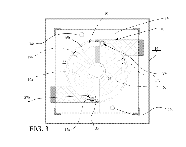
Referring now to FIG. 3, the micro electrostatic motor device 10 in a
subsequent stage of fabrication is shown. The rotor 20 is shown in phantom
with the
bridges (removed). The micro electrostatic motor device 10 includes the pair
of
electrodes 36, 38 (used as stators) disposed on the membrane layer 24 over the
body
14 and which electrodes are electrically isolated by a gap 35. Each of the
electrodes
36, 38 has a corresponding one of a pair of holes 36a, 38a. Holes 36a and 38a
will
house conductive vias to provide electrical connections to supply voltages to
the
electrodes 36 and 38, respectively.
The second membrane 37 has a pair of holes 37a, 37b. Holes 37a and 37b are
in alignment with a circular path that the tabs 17a-17c travel as the rotor 20
rotates.
The pair of electrodes 36, 38 in addition to being electrically isolated from
one
another are also electrically isolated by the membrane layer 24 from the
electrodes
16a-16c disposed on the body 14 and their associated tabs 17a-17c. In FIG. 3,
the
tabs 17a-17c are shown in darkened phantom lines for ease in viewing in
conjunction
with an explanation below. The electrodes 36 and 38 are also patterned in
regions
about member 18 to be physically and electrically isolated from member 18.
Shaft implementation
Referring now to FIGS. 4, and especially FIGS. 4A and 4B, a shaft
implementation is shown. In a shaft implementation, during construction of the
motor
10, e. g., following construction of the rotor 20 and prior to adding the
membrane
layer 24, an adhesive layer 23 is patterned and portions 23a, 2b thereof
remain on the
top surfaces of the walls (referenced in FIG. 1) of the body 14 and in a
region about
CA 03099797 2020-11-09
WO 2019/236676
PCT/US2019/035536
the center of the rotor 20 (the region about the center of the rotor that will
form the
shaft 18'). The membrane layer 24 provided over the motor 10 adheres to the
top
surfaces of the walls of the body 14 and to the center of the rotor 20. Other
portions
of the membrane 24 are in contact with, but do not adhere to other portions of
the
motor 10, e.g., the rotor 20. Thus, the rotor 20 is free to rotate, being
confined in one
dimension by the membrane 24 (and a backside membrane 28). The membrane layer
24 is patterned leaving an annular void (i.e., the gap 19a), as shown. This
annular
void or gap 19a leaves the portion of the membrane 24 that is adhered to the
center of
the rotor 20 free to rotate thus allowing that center portion of the membrane
to
'ft) provide a portion of shaft 18'.
In FIG. 4B, a second adhesive layer (not shown) is patterned to have adhesive
material (not shown) remaining on the bottom surfaces of the walls of the body
14
and a central region of the rotor. A second membrane 28 is disposed to adhere
to the
bottom surfaces of the walls of the body 14 and in the center region on the
backside of
the motor 10. The second membrane layer 28 adheres to, e.g., the bottom
surfaces of
the walls of the body 14 and to the center of the backside of the rotor 20.
The second
membrane layer 28 is patterned leaving a second annular void. This second
annular
void 29a leaves the portion of the membrane 28 that is adhered to the center
of the
backside of the rotor 20 free to rotate thus carrying the shaft 18' to the
bottom of the
motor 10. The second membrane 28 can carry a ground plane (as shown) if
desired.
The front side and the backside can be thinned if desired.
A motor element 10 with a shaft 18' is thus provided by the body layer 14 that
is sandwiched between two body membrane layers 24 and 28. The shaft 18' can
extend to and (in some embodiments through) one or both major opposing
surfaces of
the motor 10.
Axle implementation
Referring now to FIG. 5 and 5A, in an axle implementation, during
construction of the motor 10, the body layer 14 is patterned to provide the
rotor 20
and the central member 18 physically spaced via gap 19a from the rotor 20 (see
FIG.
5A). Following construction of the rotor 20, prior to adding a membrane 24'
(functionally similar to membrane 24, except for certain patterning
differences).
11
CA 03099797 2020-11-09
WO 2019/236676
PCT/US2019/035536
In FIG. 5A, an adhesive layer (not shown) is patterned leaving first regions
23a of adhesive on the top surfaces of the walls (referenced in FIG. 1) of the
body 14,
a second region 23b of adhesive on the central member 18, and a third region
23c that
is an annular region of adhesive spaced from the second region 23b of adhesive
material. The membrane layer 24' is disposed over the adhesive regions 23a-
23c.
The membrane layer 24' adheres in the regions having the adhesive material,
i.e., to
the top surfaces of the walls of the body 14, the center region of the rotor
20 (due to
the second region 23b of adhesive material) and in the third region 18c the
annular
region of adhesive material. Other portions of the membrane 24' are in contact
with,
but not adhered to other portions of the motor 10, e.g., the rotor 20, and
thus the rotor
is free to rotate confined by the membrane 24'.
In FIG. 5A another adhesive layer (not shown) provided on the membrane 24'.
The membrane layer 24' is patterned leaving a first annular void 19b aligned
with the
gap 19a that is between the first region 23a and the second region 23b of
adhesive
15 material (of the body member 14). The membrane layer 24' is further
patterned
leaving a second annular void 19c spaced from the annular gap 19b, as shown.
The
first annular void 19b is disposed about the portion of the membrane 24' that
is
adhered to the member 18 via the adhesive region 23b (of the body member 14).
The
adhesive layer (not shown) on the membrane 24 is patterned leaving adhesive
material
20 on regions 47a, 47b and 47c.
A body layer 48 is disposed on the patterned membrane 24' and the body layer
48 is patterned to leave body walls (not referenced), a central portion 48a,
spaced by a
gap 19d from an annular member portion 48b of the body layer 48, and the
annular
member portion 48b spaced from the body walls (not referenced), by an annular
void
19c. Because the member 18 is physically spaced from the rotor 20, and yet the
member 18 is adhered to the membrane 24' (and a corresponding backside
membrane
28'), the member 18 is fixed and will not rotate, as rotor 20 rotates. Thus,
member 18
in this implementation acts as an axle 18".
The axle 18" is carried through layers 24' and 48 to the top of layer 48. As
an
axle 18" as the rotor 20 rotates about the fixed axle 18", the arrangement of
the
motor 10 and the axle 18" can provide a fan or blower element (by for example
adding fins or blades to the rotor element 20.
12
CA 03099797 2020-11-09
WO 2019/236676
PCT/US2019/035536
Referring to FIG. 5B, because the membrane layer 24' was also patterned
leaving the annular region 48b of the body layer 48 between the annular void
19d and
the annular void 19e, the annular region 48b is adhered to the rotor 20 (via
adhesive
regions 47c and 18c). This annular region 48b effectively leaves a small
(width
dimension) collar 21 about the fixed axle 18" that rotates along with rotation
of the
rotor 20. The collar 21 isolates the rotor 20 from the membrane 24' and the
body
layer 48.
A second adhesive layer (not shown) is patterned to have adhesive material
remaining on the bottom surfaces of the walls of the body and a second
membrane 28'
to is disposed on the bottom surfaces of the walls of the body 14. This
second
membrane 28' (similar to membrane 28 FIG. 4A except for patterning) can be
provided with just an adhesive region on the central portion, as shown. In
some
implementations, the axle 18" can be extended to the backside of the motor 10
repeating the processing discussed above. A motor element 10 with an axle 18"
is
thus provided by the body layer 14 that is sandwiched between two 5 micro body
layers. The axle 18" can extend to one or both major opposing surfaces of the
motor
10. Another membrane 52 can be affixed to the body layer 48 with appropriately
patterned adhesive regions on the body layer.
An assembled motor 10 having an axel 18" is shown in FIG. 5B, with body
layer 48 over membrane 24' body layer 14 and membrane 28'. A pictorial
representation of an assembled motor 10 (shaft implementation) is shown in
FIG. 6.
Operational principles
The rotor 20 has the electrodes 16a-16c that collect charge and discharge
collected charge as the rotor 20 rotates between the electrodes 16a-16c and
the
electrodes 36 and 38. Effectively, therefore, between the electrodes 16a-16c
and the
electrodes 36 and 38 are capacitor elements that build up charge and discharge
that
charge, as explained above. The charge is dynamic and is related to the
capacitance
provided by the effective capacitors that are the combination of the
electrodes 16a-16c
and the electrodes 36 and 38 and the dielectric material between these
electrodes.
Considering the dielectric constants of the dielectric material between the
electrodes
16a-16c and 36 and 38, the area of overlap of these electrodes, and the
distance
between overlapping pairs of these electrodes 16a-16c and 36 and 38 these
capacitors
13
CA 03099797 2020-11-09
WO 2019/236676
PCT/US2019/035536
will have capacitances, at least approximated by a formula for a parallel
plate
capacitor, given as:
C = (Er + co)A/d
Where C is the capacitance, in farads; A is the area of overlap of the two
electrodes,
in square meters; Er is the dielectric constant of the material between the
electrodes
(sum of dielectric constants of a membrane and fluid); co is the electric
constant (Co
8.854x10⁻¹² F=m-1); and d is the separation between the plates, in meters,
where d is
sufficiently small with respect to the smallest chord of A.
Compared to a conventional electrostatic motor used for similar purposes, the
electrostatic motor 10 may use less material, and thus is subject to less
stress. The
electrostatic motor 10 has a size in the micron to millimeter scale.
Asynchronous Motor Operation
Operation of the motor 10 as an asynchronous motor can be explained as
follows: Consider a voltage applied between the electrodes 16a-16c and
electrodes 36
and 38. Placing a voltage potential difference between the electrodes 16a-16c
and the
electrodes 36, 38, will have, e.g., positive charge on the electrodes 16a-16c,
e. g., 16a
and, e.g., negative charge on the electrodes 36, 38, e.g. electrode 38. With
electrode
16a having a positive charge and electrode 38 having a negative charge
(relative to the
charge on 16a), this occurrence will cause the rotor 20 to rotate by
attraction of
opposite charges. As the rotor 20 rotates initially there is no transfer of
charge from
the electrode 16a to the electrode 38 due to the dielectric properties of the
material(s)
separating the electrode 16a from the electrode 38 and due to the relative
distance of
the electrode 16a from edges of the electrode 38.
However, as an attractive force or torque is produced due to the positive
.. charged electrode 16a being attracted to the negatively charged electrode
38, causing
the rotor 20 to rotate (in a counter clockwise direction) and also causing the
positively
charged electrode 16a to be drawn under the electrode 38. The rotor 20
carrying this
positively charged electrode 16a has some momentum and will continue to travel
under electrode 38.
However, once one of the tabs 17a-17c of one of the electrodes 16a-16c is in
alignment with one of the holes 37a, 37b in membranes, over which is the
respective
14
CA 03099797 2020-11-09
WO 2019/236676
PCT/US2019/035536
one of electrodes 36, 38, that alignment results in a net transfer of charge
from the
aligned one of the tabs 17a-17c of the corresponding one of the electrodes 16a-
16c on
the rotor 20 to the stator electrode 36 or 38.
In the context of FIG. 3, assuming that electrode 38 is negative with respect
to
electrode 36, e.g., +500 V on electrode 36 and e.g., 0 V on electrode 38, when
tab 17a
of the electrode 16a becomes in alignment with hole 37b (assuming that it was
initially possible charged) a net transfer of charge occurs between the tab
17a (and
concomitantly therewith electrode 16a) and stator electrode 38 by arcing of
the charge
from the electrode 16a to the electrode 38 through the hole 37b. This transfer
of
charge provided by the arcing of charge from the tab 17a to the electrode 38
leaves
the electrode 16a at a net negative charge that now repels the electrode 16a
away from
electrode 38 and towards electrode 36 that is at a positive charge. Thus,
while
electrodes 16a-16c are under electrodes 36, 38 there is a charge difference
and thus
attraction, until the electrode's tab comes under one of the holes 37a, 37b in
the
electrodes 36, 38, which results in a discharge and repulsion force.
The transfer of charge occurs via an arcing of charge, e. g., an arc (not
shown)
from one electrode, e.g., electrode 16a having a positive charge through the
hole, e.g.,
hole 37b to a nearby electrode, e.g., electrode 38 having a negative charge
from the
tab 17a being in proximity to the hole 37b. The arc is produced between the
respective one of electrodes 16a-16c (in this explanation electrode 16a via
tab 17a) to
the corresponding one of the electrodes 36, 38 (in this explanation electrode
38) by
virtue of the tab 17a being sufficiently close to the hole 37b, and the hole
37b having
a low dielectric constant, e.g., that of air, which is lower than the
dielectric constant of
the material separating the electrodes 16a-16c from the electrodes 36, 38.
The arc is generated when charge is transferred from one electrode to another
electrode. The arc occurs provided that the breakdown voltage of the
dielectric that
separates the electrodes is overcome. Consider a 5 micron thick membrane that
carries an conductive layer of 50 to 500 Angstroms thick, the dielectric
breakdown
voltage for air is about 3V per micron, thus for air any voltage in excess of
about 15
volts will cause an arc to occur when one of the tabs 17a-17c is alignment
over one of
the holes 37a or 37b. However, the arc that is generated is of sufficiently
low energy
(i.e., an extremely low current and hence extremely low power) so as not to
adversely
CA 03099797 2020-11-09
WO 2019/236676
PCT/US2019/035536
affect any of the materials that comprise the motor 10. Thus applied voltages
of 15 to
500 volts can be applied. More specifically voltages in a range of 15 to 250
volts and
more specifically 20 to 50 volts, etc. can be used.
Suffice it to say that the applied voltage would be between the minimal
voltage needed to guarantee arcing under the conditions specified above and
the
maximum voltage being the voltage that would cause some deleterious effects on
the
materials of the motor 10. Therefore, other voltage ranges would be within the
scope
of this teaching.
Synchronous Motor Operation
In some implementations, the motor 10 can be operated as a synchronous
motor. The synchronous motor example can consider the motor as a variable
(rotary)
capacitor. A square-wave voltage or sinusoidal wave is applied across
electrodes 16a-
16c and electrodes 36 and 38. When the motor 10 is running synchronously, the
rotor
turns one half of a revolution in a one cycle of the voltage. In the quarter
15 revolution, when the rotor 20 and electrodes 16a-16c and stator
electrodes 36, 38 are
approaching each other there is a voltage between that attracts each other
due, e.g.,
electrodes 16a-16c being positive and stator electrodes 36, 38 being negative.
During
the next quarter revolution the voltage applied is zero, but the rotor 20
continues to
rotate due to inertia.
20 Referring to FIG. 7, a stacked arrangement 10' of two of the motors 10
of FIG.
4 (shaft implementation having shaft 18') is shown with a spacer layer 40
(optional).
The stacked arrangement 10' includes the two motors 10 of FIG. 4 (each having
body
layers 14 with membranes 24, 28) and can include top and bottom caps (not
shown) or
a case (not shown) provided to seal the motors. The caps could be additional
body
layers that are not patterned, but which are affixed to top and bottom layers
of the
finished motors 10. A stacked arrangement of two motors 10 of FIG. 5, i.e.,
the axle
implementation, could also be provided along with top and bottom caps (not
shown)
or a case (not shown).
Micro-mechanical force transfer device overview
In some implementations, the micro electrostatic motor 10 (either shaft or
axle
versions) can be used with micro mechanical force transfer devices.
16
CA 03099797 2020-11-09
WO 2019/236676
PCT/US2019/035536
Micro mechanical force transfer devices described herein are made using
micro fabrication methods. The micro mechanical force transfer devices
described
herein are of the gear type and generally include one or more gears. Plural
gears can
be intermeshed together in a single module to provide a gear train. Gears can
be built
up in repeatable layers (of gear modules) to provide complex gearing
arrangements of
various types. These micro mechanical force transfer devices can be used to
accomplish various aspects of mechanical force transfer. For example, the
micro
mechanical force transfer devices can be used for increasing or decreasing
rotational
velocity; increasing or decreasing torque, or changing the plane of rotation
or
o changing the direction of rotation (i.e., reversing direction of
rotation) of an input
force. The input force can originate from either version of the electrostatic
motors
mentioned above or from other sources. These micro mechanical force transfer
devices can find applications in various industrial, commercial, medical, and
biological applications. Micro mechanical force transfer device are fabricated
on a
micron/millimeter scale using roll to roll processing techniques that will be
discussed
below.
Referring to FIGS. 8A and 8B, a first stage 110a of a micro mechanical force
transfer device 110 in a stage of construction is shown. The micro mechanical
force
transfer device 110 is a gear train device that transfers mechanical force
from one
driven gear referred to herein as the input gear to another gear referred to
herein as the
output gear. The first stage 110a includes the input gear 112 that is inter-
meshed with
the output gear 114. In this example, the first stage 110a of the micro
mechanical
force transfer device 110 (gear train) reduces rotational speed and increases
torque
between an input force at the input gear 112 and an output force from the
output gear
114. However, a gear train that increases rotational speed and reduces torque
between
the input gear and the output gear could alternatively be built by the input
gear having
more teeth than the output gear.
The micro mechanical force transfer device 110 includes a gear body frame
116 supported on a membrane 140. The gear body frame 116 has plural walls,
e.g.,
four walls 116a-116d, with interior portions of those walls 116a-116d defining
an
interior chamber 118. The walls, e.g., walls 116a-116d could optionally have
ports
that provide fluid ingress or egress from an external fluid source and an
external fluid
17
CA 03099797 2020-11-09
WO 2019/236676
PCT/US2019/035536
sink (not shown). In other embodiments the walls 116a-116d are solid walls
without
ports, as shown.
Also shown in FIG. 8A are tether members 113a, 113b and 115. These tether
members are bridge elements patterned from the gear body 116 and are used to
tether
the gears 112 and 114 to the gear body 116 during fabrication processes.
Tethers
(only three shown) 113a, 113b, 115 are used to keep moveable, rotatable parts
in
place during early stages of manufacture, but are removed prior to final
assembly.
Interior portions of the chamber 118 including gaps between teeth can be
filled with a
lubricating fluid of a low viscosity to provide fluid lubrication and
mechanical
to damping. The first gear 112 is tethered via the pair of tether elements
113a, 113b to
the second gear 114. The second gear 114 is tethered to one of the walls 116a-
116d,
e.g., wall 116d of the gear body 116 by the tether element 115.
Referring to FIG. 8B, a body layer 116 is patterned to provide a gear support
structure 125. The first gear 112 is coupled to either a shaft or an axle (not
shown)
and is supported by a first gear support element 122 and the second gear 114
is
supported by a second gear support element 124 of the gear support structure
125.
The first gear support element 122 and the second gear support element 124 are
positioned under the respective gears 112, 114 to support those gears, as will
be
discussed below.
Optionally, the second gear 114 in some instances could be coupled either to a
shaft (not shown) or an axle (not shown) of the mechanical interface 142, but
typically a optional second mechanical interface (not shown) would be
positioned
over the device 110 to couple to the second gear 114.
In one implementation of the mechanical interface 142, the micro mechanical
force transfer device 110 is coupled to the shaft 18' of the motor 10 (FIGS.
4, 4A, 4B)
and is built up from the motor 10, as will now be described.
Referring now to FIG. 9, starting with the motor of FIGS. 4, 4A and 4B, (view
of FIG. 4B shown) the membrane layer 24 is provided with an adhesive layer
(not
shown) that is patterned to provide adhesive regions 129a around the membrane
24
over walls 14a-14d (FIG. 1) of the body layer 14 and a central region 129b.
For
simplicity, the rotor, conductors, etc. are shown but not referenced. On an
underside
of the body 14 is the membrane 28.
18
CA 03099797 2020-11-09
WO 2019/236676
PCT/US2019/035536
Body layer 128 is disposed over the membrane 24 and adheres to the
membrane in regions 129a, 129b having the adhesive. The body layer 128 is
patterned to provide an appropriate gear body support structure 125 (analogous
to the
support structure 125 of FIG. 8B) configured according to the gears that will
be
provided. The gear body support structure 125 has features of a size similar
to those
of the gears, e. g., 112, 114 (FIG. 8). The body layer 128 is patterned to
provide an
annular gap 127 that provides a central region of the material of the body
layer 128.
(This would be provided for each gear, only gear 112 being shown in cross-
section.)
An adhesive layer (not shown) is patterned to provide regions 129a and 129b.
Another membrane 131 is provided on the body layer 128 with patterned adhesive
layers 132a, 132b followed by the gear body layer 116 (see FIGS. 8A and 8B). A
surface of the central region of body layer 128 opposite to that having the
adhesive
129b adheres to the shaft 18' of the motor 10.
A combination of another membrane layer, gear body support, membrane and
gear body layer (all with appropriate patterned adhesive layers and gaps) can
be
provided over that shown in FIG. 9 to build up a gear train in a vertical
dimension. In
addition, many more such combinations of a membrane, a gear support, a gear
layer
and a membrane could be provided to build up complex gearing structures. In
addition, many more such gears could be provided within a particular gear body
layer
with corresponding gear support layer features.
In another implementation of the mechanical interface 142, the micro
mechanical force transfer device 110 is coupled to the axle 18' of the motor
10 (FIGS.
5, 5A, 5B) and is built up from the motor 10, as will now be described.
Referring now to FIG. 10, starting with the motor 10 of FIGS. 5, 5A and 5B
(view of FIG. 5B shown), the motor 10 includes body layer 14, membrane 24' and
membrane 28' with axle 18", and body layer 48 is provided with an adhesive
layer
(not shown) that is patterned to provide an adhesive region 152a around the
body
layer 48 aligned over walls 14a-14d (FIG. 1) of the body layer 14, an annular
adhesive region 152b and a central region 152c. For simplicity, the rotor,
conductors,
etc. are shown but not referenced. A membrane 154' having patterned annular
voids
(not referenced) is provided over the body layer 48 and adheres to the body
layer 48
in adhesive regions 152a-152c.
19
CA 03099797 2020-11-09
WO 2019/236676
PCT/US2019/035536
In some implementations, a body layer 158 is disposed over the membrane
154' and adheres to the membrane 24' in regions shown but not referenced
having
adhesive. The body layer 158 is patterned to provide a gear body support. The
gear
body support has features of a size and extent similar to features of the
gears that will
be provided. The features are patterned to provide an annular gaps 157a and
157b
that provide a central region 159 of the material of the body layer 158. (This
would
be provided for each gear, only gear 112 being shown in cross-section.) In
some
implementations, the layer 48 can be provided as the gear support layer, in
which case
body layer 158 would not be used.
to An adhesive layer not shown is patterned to provide regions 159a and
159b.
Another membrane 160 is provided on the body layer with patterned adhesive
layers
162a, central region 162b and annular region 162c followed by the gear body
layer
116 (FIGS. 8A, 8B).
A combination of another membrane layer, gear body support, membrane and
gear body layer (all with appropriate patterned adhesive layers and gaps) can
be
provided over that shown in FIG. 10 to build up a gear train in a vertical
dimension.
In addition, many more such combinations of a membrane, a gear support, a gear
layer and a membrane could be provided to build up complex gearing structures.
In
addition, many more such gears could be provided within a particular gear body
layer
with corresponding gear support layer features.
Referring now to FIG. 11, a second stage 111b of the micro mechanical force
transfer device 110 is shown in a stage of construction. The second stage 111b
has a
gear body 166 with walls 166a-166d enclosing a chamber 167is another gear
train that
transfers mechanical force from a third gear 172, e.g., the driving gear or
input gear to
a fourth gear 174, e.g., the driven or output gear of the second stage. In
this example,
the micro mechanical force transfer device stage 111b shown is a second gear
train
that further reduces rotational speed and increases torque between the input
gear 172
and the output gear 174. The second stage 111b includes membrane layers (not
shown) a gear support layer (not shown) and the gear layer 111b that can be
provided
using either the principles discussed for FIG. 9 or FIG. 10 (shaft or axle
versions).
The gears are tethered with tethers (shown but not referenced).
CA 03099797 2020-11-09
WO 2019/236676
PCT/US2019/035536
In operation, one of the gears acts as an input or driving gear, e.g., gear
172
and the other gear, e.g., gear 174 acts as an output or driven gear. In the
micro
mechanical force transfer device 10 described, the input gear 172 is driven
from the
first stage 111a (FIG. 1) from the output gear 114 of the micro mechanical
force
transfer device 110 to transfer force from the first stage 111a to the second
different
stage 111b of the micro mechanical force transfer device 110. The gears 172,
174 are
rotatable either about axles or rotating shafts.
Referring now to FIG. 12, a stacked micro mechanical force transfer device
110' having three gear layers (pictorially represented but each being
constructed
according to FIGS. 8A - 10) with the electrostatic motor 10 is shown. The
phantom
lines represent inter-stage connection points between gears of adjacent stages
and the
arrows represent rotation directions. Stage 1 (51) is a driver stage that
includes a
motor such as the shaft or axle versions of FIGS. 4 or 5. Stages 2 and 3 (S2
and S3)
are each speed reduction, torque increasing stages that reverse rotational
directions.
Stage 4 (S4) is a buffer stage that maintains the same direction and speed at
the output
as the input direction and speed at the input to the stage.
Manufacturing
The electrostatic motor 10 and the micro mechanical force transfer device 10
having the above described features can be manufactured using various methods
such
as MEMS processing techniques and so-called roll to roll (R2R) processing. The
materials for the electrostatic motor 10 are chosen based on the features to
be
provided by the electrostatic motor 10 and the method of manufacturing of the
electrostatic motor 10. Below are some criteria for choosing the materials of
the
different parts of electrostatic motor 10.
Motor force transfer device body ¨ The material used for the motor body 14
(as well as bodies 24 and 44 and force transfer bodies) may be defined by the
requirements. In general, the material needs to be strong or stiff enough to
hold its
shape to produce the chamber. In some implementations, the material is
etchable or
photo sensitive so that its features, e.g., the rotor 20 and chamber 12, etc.,
can be
defined and machined/developed. Sometimes it is also desirable that the
material
interact well, e.g., adheres, with the other materials in the electrostatic
motor 10.
21
CA 03099797 2020-11-09
WO 2019/236676
PCT/US2019/035536
Furthermore, the material is electrically non-conductive. Examples of suitable
materials include SU8 (negative epoxy resist), and PMMA (Polymethyl
methacrylate)
resist.
Membranes ¨ The material for this part can be an elastic material that along
with the body 14 or the force transfer bodies carries conductive layers from
which the
various electrodes are provided. As such, the material if elastic can bend or
stretch
back and forth, but such elastic characteristics are not required. The
membrane
material is impermeable to the fluids of interest, including gas and liquids,
is
electrically non-conductive, and can have either a low or a high breakdown
voltage
to characteristic. Examples of suitable materials include silicon nitride,
and Teflon.
Others materials that are stiff are also possible.
Electrodes ¨ The material of the electrodes is electrically conductive.
Because
the electrodes do not conduct significant amounts of current, the material can
have a
high electrical sheet resistance, although the high resistance feature is not
necessarily
desirable. The electrodes are subject to bending and stretching with the
membranes,
and therefore, it is desirable that the material is supple to handle the
bending and
stretching without fatigue and failure. In addition, the electrode material
and the
membrane material adhere well, e.g., do not delaminate from each other, under
the
conditions of operation. Examples of suitable materials include very thin
layers of
gold and platinum. Others are possible.
Electrical interconnects ¨ The voltages from the capacitance measurement
circuits are conducted to the electrode on each membrane of each chamber.
Electrically conducting paths to these electrodes can be built using
conductive
materials, e.g., gold and platinum.
Other materials ¨ when MEMS processing is used in manufacturing the micro
electrostatic motor 10, a sacrificial filling material, e.g., polyvinyl
alcohol (PVA), can
be used. The sacrificial filling material may also be used in R2R processing.
In some
implementations, solvents are used in the manufacturing process, which may
place
additional requirements on the various building materials of the micro
electrostatic
motor 10. It may be possible to print some of the electrical circuit
components onto
the membranes. In general, while certain materials have been specified above,
other
materials having similar properties to those mentioned could be used.
22
CA 03099797 2020-11-09
WO 2019/236676
PCT/US2019/035536
End plates (not shown in the figures) can be placed above and below the
finished motor 10 to protect the electrodes and membranes, etc. from an
ambient. The
finished motor 10 can be packaged in various types of packages such as those
used for
integrated circuits.
As mentioned above, while several approaches can be used to fabricate the
electrostatic motor 10, such as MEMS processing (Microelectromechanical
systems)
techniques discussed below will be techniques for fabrication by roll to roll
processing that can also be applied to formation of other types of
devices/systems.
Roll to Roll processing for producing the micro electrostatic motor and the
micro mechanical force transfer device
A roll to roll processing line can comprises several stations that can be or
include enclosed chambers at which deposition, patterning, and other
processing
occurs. Processing viewed at a high level thus can be additive (adding
material
exactly where wanted) or subtractive (removing material in places where not
wanted).
Deposition processing includes evaporation, sputtering, and/or chemical vapor
deposition (CVD), as needed, as well as printing. The patterning processing
can
include depending on requirements techniques such as scanning laser and
electron
beam pattern generation, machining, optical lithography, gravure and
flexographic
(offset) printing depending on resolution of features being patterned. Ink jet
printing
and screen printing can be used to put down functional materials such as
conductors.
Other techniques such as punching, imprinting and embossing can be used.
The original raw material roll is of a web of flexible material. In roll to
roll
processing the web of flexible material can be any such material and is
typically glass
or a plastic or a stainless steel. While any of these materials (or others)
could be used,
plastic has the advantage of lower cost considerations over glass and
stainless steel.
Specific materials will be determined according to the application of the
micro
electrostatic motor 10. In applications materials such as stainless steel or
other
materials that can withstand encountered temperatures would be used, such as
Teflon
and other plastics that can withstand encountered temperatures. With stainless
steel
however there would be considerations of dielectrics need to ensure electrical
isolation among the various elements.
23
CA 03099797 2020-11-09
WO 2019/236676
PCT/US2019/035536
For the structure shown, stations within a roll to roll processing line are
set up
according to the processing required. Thus, while the end cap and top caps
could be
formed on the web or plastic sheet in one implementation the end and top caps
are
provided after formation of the micro-electrostatic motor 10 stack, as will be
described.
Referring now to FIG. 13, a flow diagram that depicts roll to roll processing
180 to provide the motor 10 is shown (similar processing is used for the micro
mechanical force transfer device 110). A sheet of a flexible material (not
shown)
such a non-metalized 50 micron thick sheet is provided 182 with a double sided
adhesive over a major surface and which will be used as the body layer 14
(FIG. 1).
The adhesive is a type 1801. For the particular implementation the motor 10,
the
material is polyethylene terephthalate (PET). Other materials could be used.
The sheet with the adhesive is patterned 184 to clear the adhesive from all
regions that will correspond to moving parts. Thus, for example portions of
the sheet
correspond to the rotor 20 and member 18 portions (FIG. 1) do not have regions
of
adhesive. A mask (not shown) is used to configure a laser ablation station to
remove
the adhesive from areas of the sheet within which the those features will be
formed.
The sheet is micro-machined 186 using another mask (not shown) or direct
write to configure a laser ablation station to define or form the chamber 12
and the
rotor 20 tethered as discussed in FIG. 1. Vias are also provided for
electrical
connections. The micro-machining ablates away the plastic to form the chamber
12,
rotor 16, and member 18 in the body 14 (FIG. 1).
In embodiments in which the member 18 is not fixed but rotates there is a
small gap between the electrodes on rotor 20 (through the metal, but not the
body
layer) and the member 18, and the layer of adhesive 18a is not used. In
embodiments
in which the member 18 is fixed, there is a small gap between the rotor 20
(through
the metal and body layer) and the member 18 and the layer of adhesive 18a is
used.
The sheet with the micro-machined chamber 12, rotor 20 and member 18 is
laminated 188 on both sides to a pair of membrane sheets, e.g., 5 micron thick
sheet
of PET with a metallic layer of Al of 100A thickness. The sheet is laminated
188 on
both sides to the membrane sheets with the metallic layers of those sheets
facing
outwards from the body, providing a composite sheet.
24
CA 03099797 2020-11-09
WO 2019/236676
PCT/US2019/035536
The membrane sheets are patterned 190 to form the patterned electrodes 16a-
16c and tabs 17a-17c carried by the membranes and providing the rotor 20
disposed in
the chamber 12 of the body 14. The rotor 20 is attached to the member 18,
allowing
both to freely rotate within the chamber 12 (FIG. 4). The sheets are machined
to
provide alignment holes (not shown) prior to or subsequent to coating with the
metallic layer.
The sheets supporting the patterned electrodes are laminated 7192 between a
pair of prefabricated sealing layers disposed on both sides of the sheets. The
sealing
layers are 50 micron sheets having a 1801 adhesive. The prefabricated sealing
layers
.. are patterned to cut 74 electrode access notches for electrical
connections.
The composite sheet is processed to cut 196 release points to release moving
parts, such as the rotor 20 and member 18, cut alignment pin holes (not shown)
that
are used to position the motor 10 in a fixture and cut stitches that are used
to singulate
motors from sheet arrays. The composite sheet is laminated 198 with a second
pair of
prefabricated sealing layers (only layer 182 shown) disposed on both sides of
the
sheet 170, with the sealing layers being 50 micron sheets having 1801
adhesive.
FIGS. 14A-14D and 15A-15F show stages exemplary of roll to roll
processing to form gear trains respectively for shaft and axle implementations
on the
motor 10.
FIGS. 14A-14D show respectively stages of the patterned adhesive on the
motor body, patterned membrane layer, patterned body layer with gear support
layer
features and gear with tethers for shaft versions.
In particular shown in FIG. 14A is the central disk 16 without tethers to the
body 14, in FIG. 14B is shown a membrane layer over the arrangement in FIG.
14A.
.. In FIG. 14C is shown a tether arrangement that has four tethers 200a-200d
securing a
gear support to walls of the gear support body over the central disk 16 and
four tethers
202a-202d tethering the shaft to the gear support. In FIG. 14D is shown
another
tether arrangement that has four tethers 210a-210d securing a gear to walls of
the gear
module and supporting the gear over the gear support of FIG. 14C.
FIGS. 15A-15F show respectively stages of the patterned adhesive on the
motor body, patterned membrane layer, patterned body layer with gear support
layer
CA 03099797 2020-11-09
WO 2019/236676
PCT/US2019/035536
features, collar formation layer, membrane layer, and gear with tethers for
axle
versions.
In particular shown in FIG. 15A is the central disk 16 without tethers to the
body 14, in FIG. 14B is shown a membrane layer 24' over the arrangement in
FIG.
14A patterned to provide the two annular gaps 19b, 19c (FIG. 5A). In FIG. 15C
is
shown a tether arrangement that has four tethers (not referenced) that secures
a gear to
walls of a gear body over the central disk 16. In FIG. 15D is shown the tether
arrangement that has the four tethers cut (not referenced). In FIGS. 15E and
15F is
shown formation an external interface of the axle implementation.
The figures of FIG. 14A-14D and FIGS. 15A-15F roughly correspond to
exemplary masks for etching of the corresponding features.
The above techniques can also use a machine vision system produce a data file
that is used by the laser ablation system in aligning a laser ablation station
with a
mask (or direct write) such that a laser beam from the laser ablation system
provides
features according to the mask used in registration with the corresponding
portions of
the bodies, as discussed. The electrodes are formed by ablating away the metal
in
regions that are not part of the electrodes and conductors, leaving isolated
electrodes
and conductors on the sheet.
Aug or test fixture (not shown) can be used in conjunction with the alignment
pin holes. Other stacking techniques for assembly are possible with or without
the
alignment pin holes.
Via conductors to interconnect the patterned electrodes on stacked motors 10
are connected via conductors that are castellated structures, i.e., with
relatively wide
areas contacting electrode tabs and relatively narrow areas through holes in
the
electrode. This arrangement is provided by having the holes in the body
portions
larger than the holes through the electrode portions. This can be accomplished
during
the patterning stages of the body and the electrodes respectively. The via
conductors
are formed by introduction of the conductive inks mentioned above into the
holes.
Elements of different implementations described herein may be combined to
form other embodiments not specifically set forth above. Elements may be left
out of
the structures described herein without adversely affecting their operation.
26
CA 03099797 2020-11-09
WO 2019/236676 PCT/US2019/035536
Furthermore, various separate elements may be combined into one or more
individual
elements to perform the functions described herein.
Other embodiments are within the scope of the following claims. For example
other techniques to adhere (i.e., affix) layers together could be used such as
laser
welding, etc.
27