Note: Descriptions are shown in the official language in which they were submitted.
CA 03100027 2020-11-11
WO 2019/226811 PCT/US2019/033585
A HYDROCRACKING PROCESS FOR MAKING MIDDLE DISTILLATE FROM A
LIGHT HYDROCARBON FEEDSTOCK
CROSS-REFERENCE TO RELATED APPLICATION
[0001] This application claims the benefit of U.S. Provisional Patent
Application
62/676,406 filed May 25, 2018 entitled A HYDROCRACKING PROCESS FOR MAKING
MIDDLE DISTILLATE FROM A LIGHT HYDROCARBON FEEDSTOCK, the entirety of
which is incorporated by reference herein.
FIELD OF THE INVENTION
[0002] This invention relates to a hydrocracking process for preferentially
making middle
distillate such as diesel from a relatively light hydrocarbon feedstock such
as light vacuum gas
oil.
BACKGROUND
[0003] Refineries commonly apply hydrocracking processes to convert high
boiling
hydrocarbon feedstocks to produce more valuable products such as naphtha and
the middle
distillates. The hydrocracking process also can provide for removal of organic
sulfur and
organic nitrogen from the feedstocks by application of a hydrotreating step
that is a part of an
overall hydrocracking process.
[0004] Hydrocracking is generally carried out by contacting gas oil or
other heavy
hydrocarbon feedstocks with a hydrocracking catalyst contained within a
reaction vessel in the
presence of hydrogen gas under elevated reaction temperatures and pressures to
yield lighter,
more valuable hydrocarbon products. These products typically boil within the
gasoline boiling
range of from 85 C (185 F) to 215 C (419 F) and the middle distillate
boiling range of from
150 C (302 F) to 425 C (797 F). The hydrocracking catalyst typically
includes a
hydrogenation metal component, crystalline aluminosilicate material such as X-
type and Y-
type zeolite, and a refractory inorganic oxide such as silica, alumina, or
silica-alumina.
[0005] The hydrocracking process typically includes a pretreating step
followed by a
hydrocracking step or, with some processes, two hydrocracking steps. The
pretreating step
provides for hydrodesulfurization and hydrodenitrogenation of the organosulfur
and
organonitrogen compounds in the hydrocarbon feedstock to convert them by
hydrogenation to
hydrogen sulfide and ammonia. The pretreating catalyst typically includes a
Group VIII metal
-1-
CA 03100027 2020-11-11
WO 2019/226811 PCT/US2019/033585
component and a Group VI metal component supported or combined with an
inorganic oxide
matrix material.
[0006] One type of two-stage hydrocracking process is disclosed in US
3,726,788. This
two-stage process includes two fractionation steps and two hydrocracking
stages to process a
highly aromatic hydrocarbon feedstock to obtain a high-aromatic naphtha
product and a low-
aromatic turbine fuel product. The first hydrocracking stage is carried out in
the presence of
hydrogen sulfide and ammonia in order to suppress the hydrogenation of
aromatics. The
presence of ammonia in the first hydrocracking stage feed acts to inhibit the
hydrocracking
catalyst activity that results in suppressing the hydrogenation of aromatics.
A combination of
a flash separation and a first stage fractionation is intermediate between the
first hydrocracking
stage and the second hydrocracking stage.
[0007] The combination of flash and fractionation separations provides a
high boiling, high
aromatics hydrocarbon stream having a low concentration of ammonia and
hydrogen sulfide
that is mixed with hydrogen treat gas, which contains little or no ammonia but
has a controlled
concentration of hydrogen sulfide. This mixed stream is introduced into the
second
hydrocracking stage. The controlled concentration of hydrogen sulfide of the
hydrogen treat
gas suppresses hydrogenation of aromatics. This hydrogen sulfide concentration
is controlled
also to provide for low aromatic naphtha and low aromatic turbine fuel
products that meet
desired aromatics specifications.
[0008] There is no suggestion that the two-stage hydrocracking process of
the '788 patent
can provide for easy processing of a light gas oil feedstock that selectively
produces middle
distillate and, specifically, produces high quality, low-sulfur diesel. The
process of the '788
patent requires use of two fractionation steps with the first fractionation
step intermediate
between the two hydrocracking stages. The first stage fractionator bottoms of
the process of
the '788 patent is introduced into the second stage hydrocracking reactor, and
it is not passed
to the second stage fractionator. It further is noted that there is no
suggestion by the '788 patent
of the use of stacked beds of different types of functional catalysts
providing for the selective
production of middle distillate and providing for operating flexibility.
[0009] Another two-stage hydrocracking process is disclosed in US
3,816,296. This
process provides for hydrocracking heavy hydrocarbons boiling above 700 F to
selectively
produce midbarrel fuels boiling between 300 F and 700 F and lower boiling
products such as
gasoline or naphtha fractions. The yield of these products for a given
hydrocracking conversion
is controlled and changed as desired by the controlled addition of certain
nitrogen-containing
compounds to the second-stage hydrocracking zone of the process. The nitrogen
compounds
-2-
CA 03100027 2020-11-11
WO 2019/226811 PCT/US2019/033585
include ammonia and other nitrogen-containing compounds convertible to ammonia
in the
hydrocracking zone.
[0010] The midbarrel hydrocracking catalyst of the process of the '296
patent comprises
refractory oxide support that is at least about 50 weight percent amorphous
alumina, has less
than 30 weight percent crystalline zeolite, and a hydrogenation active
component.
[0011] The process of the '296 patent includes a high-pressure scrubber-
separator and a
fractionator positioned between an initial hydrocracking reaction stage and
the second
hydrocracking reaction stage. The effluent from the initial hydrocracking
reaction stage passes
to the high-pressure scrubber-separator that provides for water scrubbing the
effluent to remove
ammonia and hydrogen sulfide. The scrubbed effluent passes to the
fractionator, which
separates it into gasoline range hydrocarbons boiling below 400 F, midbarrel
fuels boiling
between the gasoline cut point and about 700 F, and unconverted hydrocarbons
boiling above
about 700 F. The nitrogen compounds are added to the unconverted hydrocarbons
that are
passed to the second hydrocracking reaction stage. The effluent from the
second hydrocracking
reaction stage is passed to a separator and the separated liquid is recycled
to the fractionator.
[0012] A required feature of the process of the '296 patent is the use of a
fractionation step
between the first stage hydrocracking reactor and the second stage
hydrocracking reactor.
There is no suggestion of the use of stacked beds of different types of
functional catalyst
providing for the selective production of middle distillate and providing for
operating
flexibility. The use of quench gas to assist in control of the reaction
temperatures of the
hydrocracking reaction stages is not recognized by the '296 patent.
[0013] Another patent, US 8,318,006, discloses a once-through hydrocracking
process. A
feature of this process is an intermediate hot flash step placed between a
hydrorefining step and
a hydrocracking step. The intermediate hot flash provides for the separation
of at least a portion
of the ammonia from the effluent leaving the hydrorefining step. There is no
distillation of the
liquid effluent from the intermediate hot flash step before its introduction
into the second
reaction step of the process. The second reaction zone preferably comprises at
least one bed of
hydrorefining catalyst upstream of at least one bed of hydrocracking catalyst.
There is no
disclosure by the '006 patent of the use of quench gas to control
hydrocracking reaction
temperature within the second reaction zone. Controlling the quantity of
ammonia admitted to
the hydrocracking step increases the flexibility of the process and provides
for improvement in
the middle distillate selectivity of the hydrocracking catalyst.
[0014] It is sometimes desirable to process light gas oil feedstocks that
are only slightly
heavier than diesel fuel in a hydrocracking unit to preferentially yield
diesel instead of naphtha
-3-
CA 03100027 2020-11-11
WO 2019/226811 PCT/US2019/033585
or gasoline. It can be difficult, however, to hydrocrack gas oil that is only
slightly heavier than
diesel to make a high-quality diesel product, because their boiling
temperatures can overlap
which makes it difficult to control the amount of cracking to yield diesel
instead of naphtha or
gasoline.
[0015] Also, market economics sometimes make it beneficial to change the
operation of a
hydrocracking unit from a gasoline production operating mode to a distillate
or diesel
production operating mode. Thus, hydrocracker unit operating flexibility can
be important to
maximizing its operating economics. When operating a hydrocracking unit in a
diesel
production mode, the diesel should be high quality and meet ultra-low sulfur
diesel
specifications. Thus, it is important for the hydrocracking unit to include
features providing for
its operation to make high quality, ultra-low sulfur diesel.
SUMMARY
[0016] Accordingly, provided is a hydrocracking process for converting a
light gas oil
feedstock to yield a diesel product. In this hydrocracking process, the light
gas oil feedstock is
introduced into a first reaction zone defined by a first reactor and
containing a first pretreating
catalyst and whereby a first reactor effluent is yielded from the first
reaction zone. The first
reactor effluent is introduced into a second reaction zone defined by a second
reactor and
containing a first hydrocracking catalyst and whereby a second reactor
effluent is yielded from
the second reaction zone. The second reactor effluent is introduced into a
first separation zone
defined by a first separator vessel providing means for separating the second
reactor effluent
into a first separator vapor and a first separator liquid. The first separated
liquid is introduced
into a third reaction zone defined by a third reactor, wherein within the
third reaction zone is
included a top bed, comprising a second pretreating catalyst, and a bottom
bed, comprising a
second hydrocracking catalyst. A third reactor effluent is yielded from the
third reaction zone.
The third reactor effluent is introduced into a second separation zone defined
by a second
separator vessel providing means for separating the third reactor effluent
into a second
separator vapor and a second separator liquid. The second separator liquid is
introduced into a
main fractionator providing for the distillation separation of the second
separator liquid to yield
at least a bottoms product and another product.
-4-
CA 03100027 2020-11-11
WO 2019/226811 PCT/US2019/033585
BRIEF DESCRIPTION OF THE DRAWINGS
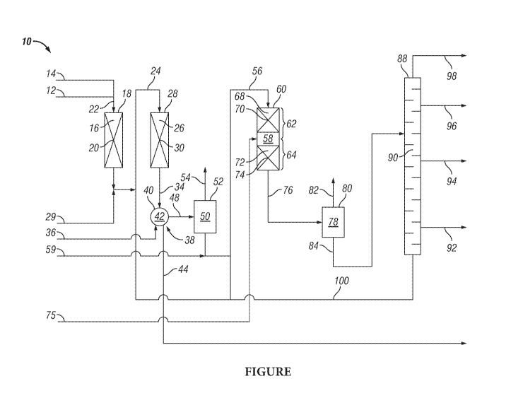
[0017] The Figure presents a process flow diagram of one embodiment of the
inventive
two-stage hydrocracking process for converting hydrocarbon feedstocks
preferentially to yield
a middle distillate product.
DETAILED DESCRIPTION
[0018] The invention relates to a two-stage hydrocracking process for
converting a light
gas oil feedstock to selectively or preferentially yield middle distillate
products, and,
particularly, ultra-low sulfur diesel. The inventive process includes elements
and features that
provide for flexible operation of the two-stage hydrocracking process between
a naphtha
production operating mode and a diesel production operating mode. The process
further
provides for hydrocracking a light gas oil feedstock having a boiling range
overlapping the
boiling range of diesel but shifted such that it is slightly higher than the
boiling range of diesel.
This feedstock is relatively lighter than most typical gas oil feedstocks
processed by
hydrocracker units; and, because of this, it is more difficult to process to
selectively yield diesel
instead of gasoline and to yield a good quality diesel product such as ultra-
low sulfur diesel.
[0019] The light gas oil feedstock may be from any hydrocarbon source, for
example,
petroleum crude oil. It is typically an atmospheric distillate or a light
vacuum distillate of
petroleum crude oil. The light gas oil feedstock may be characterized as
having an initial
boiling temperature greater than about 135 C (275 F) and a final boiling
temperature of less
than about 440 C (824 F). More specifically, the temperature at which 10
volume percent of
the light gas oil is recovered using the distillation testing method ASTM D-
86, i.e., T(10), is
greater than or about 135 C (275 F), preferably, greater than 150 C (302
F), and, most
preferably, greater than or about 165 C (329 F). The temperature at which 90
volume percent
of the light gas oil is recovered using the distillation testing method ASTM D-
86, i.e., T(90),
is less than or about 424 C (797 F), preferably, less than or about 400 C
(752 F), and, more
preferably, less than or about 375 C (707 F).
[0020] The sulfur content of the light gas oil feedstock is generally in
the range of upwardly
weight percent of the feedstock. It is more typically in the range of from 0.1
wt. % to 5 wt. %,
and, most typically, from 0.5 wt. % to 4 wt. % or 0.75 wt. % to 3 wt. %. The
sulfur content
may be determined by the testing method ASTM D 5453 or any other suitable or
comparable
testing method.
[0021] The nitrogen content of the light gas oil feedstock is normally
greater than 500 parts
per million by weight (ppmw) and usually in the range of from 500 ppmw to
5,000 ppmw.
-5-
CA 03100027 2020-11-11
WO 2019/226811 PCT/US2019/033585
More typically, the nitrogen content of the light gas oil feedstock is in the
range of from 700
ppmw to 4,000 ppmw. The nitrogen content may be determined by the testing
method ASTM
D5762 or any other suitable or comparable testing method.
[0022] The diesel product provided by the inventive hydrocracking process
has a
significantly reduced sulfur content over that of its light gas oil feedstock.
The process will
typically provide a diesel product having a sulfur content that is less than
50 ppmw, and,
preferably, the sulfur content is less than 10 ppmw. The nitrogen content is
significantly
reduced as well. The nitrogen content of the diesel product is typically
reduced to less than 50
ppmw, and it usually is in the range of from 1 to 10 ppmw.
[0023] The middle distillates yielded from the inventive hydrocracking
process can include
kerosene and diesel. While it is not preferred, the process may also yield a
product boiling
within the naphtha boiling range. It is preferred, however, to operate the
process in a diesel
production mode to preferentially yield and produce a diesel product. Indeed,
one aspect of the
inventive process is that it provides for the selective production of diesel
as opposed to kerosene
and naphtha.
[0024] The diesel product of the process is characterized as having an
initial boiling
temperature between 125 C (257 F) and 150 C (302 F) and a final boiling
temperature
between 370 C (698 F) and 400 C (752 F). It is preferred for the diesel
product to have a
T(90) temperature in the range of from 282 C (540 F) to 338 C (640 F).
[0025] The first step of the inventive process includes passing the light
gas oil feedstock
(feedstock) to the first reactor of the process unit and introducing it along
with added hydrogen
gas into the first reaction zone defined by the first reactor. Contained
within the first reaction
zone is a bed of first pretreating catalyst with which the feedstock is
contacted in the presence
of the hydrogen gas under suitable hydrotreating (i.e., hydrodesulfurization
and
hydrodenitrogenation) reaction conditions sufficient to convert a significant
portion of the
organic sulfur compounds of the feedstock to hydrogen sulfide and a
significant portion of the
organic nitrogen compounds of the feedstock to ammonia.
[0026] The first pretreating catalyst may be any known hydrotreating
catalyst that suitably
provides for the hydrodesulfurization and hydrodenitrogenation of the
feedstock. Generally,
the first pretreating catalyst comprises an inorganic oxide support material,
such as alumina,
silica, and silica-alumina, and a hydrogenation metal component. The
hydrogenation metal
may be a Group VIII metal (nickel or cobalt) or a Group VI metal (molybdenum
or tungsten)
or any combination thereof. Typically, the Group VIII metal is present in the
first pretreating
catalyst at a concentration in the range of from 1 to 20 weight percent, based
on the oxide and
-6-
CA 03100027 2020-11-11
WO 2019/226811 PCT/US2019/033585
total weight of the catalyst, and the Group VI metal is present at a
concentration in the range
of from 1 to 20 weight percent, based on the oxide and the total weight of the
catalyst. Various
of the hydrorefining catalysts disclosed and described in US Patent No.
8,318,006 may suitably
be used as the first pretreating catalyst of the process. US 8,318,006 is
incorporated herein by
reference.
[0027] The hydrotreating reaction conditions under which the first reaction
zone is
operated include a hydrotreating temperature in the range of from about 550 F
to about 850 F
and a hydrotreating pressure in the range of from about 1400 psi to 2000 psi.
The liquid hourly
space velocity (LHSV) is in the range of from about 0.1 lit' to 10 lit'. The
hydrogen treat gas
rate is in the range of from about 500 scf per barrel of feedstock to about
8000 scf per barrel of
feedstock. The hydrotreating reaction conditions within the first reaction
zone are controlled to
obtain a conversion of from 95 to 99.9 weight percent of the organic sulfur in
the feedstock to
hydrogen sulfide and from 95 to 99.9 weight percent of the organic nitrogen in
the feedstock
to ammonia.
[0028] A first reactor effluent is yielded from the first reaction zone of
the first reactor. The
first reactor effluent passes from the first reaction zone and is introduced
along with added
hydrogen gas into the second reaction zone defined by a second reactor.
Contained within the
second reaction zone is a bed of first hydrocracking catalyst with which the
first reactor effluent
is contacted in the presence of the hydrogen gas under suitable hydrocracking
reaction
conditions sufficient to provide a desired amount of hydrocracking of the
first reactor effluent.
[0029] The first hydrocracking catalyst may be any known hydrocracking
catalyst that
suitably provides for the desired first stage cracking of the first reactor
effluent. Generally, the
first hydrocracking catalyst comprises a zeolite component, an inorganic oxide
component, and
a hydrogenation metal component.
[0030] Various zeolites that may be suitable components of the first
hydrocracking catalyst
include, for example, zeolite X, zeolite Y, zeolite beta, and ZSM-5. The
zeolite component
may be present in the first hydrocracking catalyst in an amount up to about 80
wt. % of the
catalyst.
[0031] The inorganic oxide component may be selected from the group
consisting of
alumina, silica, titania, silica-alumina and combinations thereof, and it is
present in the first
hydrocracking catalyst in an amount exceeding 25 wt. % of the catalyst.
[0032] The hydrogenation metal component includes nickel or cobalt, or
both, that may be
present in the first hydrocracking catalyst in an amount in the range of from
about 1 to 10 wt. %
of the catalyst. The hydrogenation metal component further may include
tungsten or
-7-
CA 03100027 2020-11-11
WO 2019/226811 PCT/US2019/033585
molybdenum, or both, and, if present, the amount present in the first
hydrocracking catalyst is
in the range of from 5 to 25 wt. % of the catalyst. The first hydrocracking
catalyst may also
include a combination of either nickel or cobalt with either molybdenum or
tungsten.
[0033] Various of the hydrocracking catalysts disclosed and described in US
Patent No.
8,318,006 may suitably be used as the first hydrocracking catalyst. Other
possible
hydrocracking catalyst compositions are disclosed and described in US Patent
No. 7,749,373;
US Patent No. 7,192,900; and US Patent No. 7,048,845. These patents are
incorporated herein
by reference.
[0034] The hydrocracking reaction conditions under which the second
reaction zone is
operated include a hydrocracking temperature in the range of from about 550 F
to about 850
F and a hydrocracking pressure in the range of from about 1400 psi to 2000
psi. The liquid
hourly space velocity (LHSV) is in the range of from about 0.1 lit' to 10
lit'. The amount of
hydrogen mixed with the first reactor effluent is in the range of from about
500 to about 8000
scf per barrel of first reactor effluent introduced into the second reaction
zone. The
hydrocracking reaction conditions within the second reaction zone are
controlled to obtain a
desired conversion of the first reactor effluent.
[0035] A second reactor effluent is yielded from the second reaction zone
of the second
reactor and passed to a water wash step. In the water wash step, the second
reactor effluent is
mixed with wash water that provides for removing at least a portion of the
ammonia and
hydrogen sulfide contained in the second reactor effluent. Separation of the
water phase
comprising the removed ammonia and hydrogen sulfide occurs within a separation
zone
defined by a separator vessel providing means for separating the mixture of
wash water and
second reactor effluent to yield a second reactor effluent, having been
scrubbed of ammonia
and hydrogen sulfide, and a water phase, containing ammonia and hydrogen
sulfide.
[0036] The scrubbed second reactor effluent is then passed and introduced
into a first
separation zone defined by a first separator vessel. The first separator
vessel provides means
for separating the second reactor effluent into a first separator vapor, which
comprises
hydrogen gas as a major portion of the first separator vapor, and a first
separator liquid. The
first separation zone is operated under high pressure conditions that
preferably approximate the
operating pressure of the second reaction zone. Typically, the phase
separation within the first
separation zone is a single-stage, gravitational, vapor-liquid phase
separation.
[0037] The first separator liquid is then passed as a feed to a third
reaction zone defined by
a third reactor. A necessary feature of the inventive process is that there is
no intermediate
fractionation or fractional separation of the first separator liquid before it
is charged and
-8-
CA 03100027 2020-11-11
WO 2019/226811 PCT/US2019/033585
introduced into the third reaction zone. Instead, the first separator liquid
is passed directly to
the third reaction zone.
[0038] It is an essential feature of the process for the third reaction
zone to include stacked
beds of catalyst instead of a single catalyst bed. It further is a feature of
the third reaction zone
that its upper portion includes a top bed of second pretreating catalyst
instead of hydrocracking
catalyst and that its lower portion includes a bottom bed of second
hydrocracking catalyst.
[0039] The placement of the second pretreating catalyst into the upper
portion of the third
reaction zone provides several benefits in the overall operation of the
inventive hydrocracking
process. One such benefit is that it allows for greater flexibility in
operating the inventive
hydrocracking process to selectively make a high quality diesel product. It
does this by helping
to control the hydrocracking temperature within the bottom bed of second
hydrocracking
catalyst in the lower portion of the third reaction zone. The top bed that
comprises the second
pretreating catalyst fills up a portion of the third reaction zone with
catalyst having no or little
hydrocracking function resulting in less total hydrocracking catalyst
contained within the third
reactor and providing less hydrocracking than that which would be provided by
a reactor vessel
full of a hydrocracking catalyst. This reduction in the amount of
hydrocracking is required due
to the processing of a light gas oil feedstock, as defined herein, to
selectively yield a diesel
product instead of light naphtha and kerosene products.
[0040] Another benefit from the placement of the second pretreating
catalyst in the third
reaction zone as a top bed is that provides it provides for hydrogenation of
organic sulfur and
organic nitrogen compounds that were not hydrogenated in the first step of the
process and that
remain in the first separator liquid. The hydrogenation of these compounds
yield small amounts
of ammonia and hydrogen sulfide. The ammonia tends to suppress the
hydrocracking activity
of the second hydrocracking catalyst and provide for better diesel yield.
[0041] The total volume of the third reaction zone defined by the third
reactor vessel
includes a top bed volume of the second pretreating catalyst and bottom bed
volume of the
second hydrocracking catalyst. To achieve the benefits from a stacked-bed
arrangement, the
ratio of top bed volume-to-bottom bed volume within the third reaction zone
should be within
the range of 0.1:1 to 1.5:1. Preferably, this volumetric ratio is in the range
of from 0.2:1 to
1.2:1, and, most preferably, the ratio of top bed volume-to-bottom bed volume
is in the range
of from 0.5:1 to 1:1. The volume of each catalyst bed may be represented by
the cross sectional
area of the catalyst bed multiplied by the height of the catalyst bed.
[0042] The second pretreating catalyst is any known hydrotreating catalyst
that suitably
provides for the hydrodesulfurization and hydrodenitrogenation of the first
separator liquid in
-9-
CA 03100027 2020-11-11
WO 2019/226811 PCT/US2019/033585
accordance with the invention. The second pretreating catalyst may be the same
or similar to
the first pretreating catalyst as described above and may comprise an
inorganic oxide support
material, such as alumina, silica, and silica-alumina, and a hydrogenation
metal component.
The hydrogenation metal component may be either nickel or cobalt that may or
may not be
combined with molybdenum or tungsten, or both. The nickel or cobalt metal
component is
present in the second pretreating catalyst at a concentration in the range of
from 1 to 20 weight
percent, based on the oxide and the total weight of the catalyst, and the
molybdenum or tungsten
component, when present, is at a concentration in the range of from 1 to 20
weight percent,
based on the oxide and the total weight of the catalyst.
[0043] The cracking reaction within the bottom bed is further controlled by
the introduction
of lower temperature quench gas into the third reaction zone so as to control
the cracking
reaction temperature within the bottom bed. The quench gas comprises hydrogen
gas and has
a temperature significantly below the temperature within the third reaction
zone and in
particular within its bottom bed. Control of the diesel selectivity of the
cracking reaction is
assisted by controlling the cracking temperature within the bottom bed.
[0044] Additional control of the temperature within the bottom bed of the
third reaction
zone so as to control the diesel selectivity of the cracking reaction therein
is achieved by
admixing with the first separator liquid a nitrogen-containing compound
selected from the
group consisting of ammonia and organic amine compounds capable of conversion
to ammonia
under the conditions within the third reaction zone. The organic amine
compounds preferably
are selected from primary, secondary and tertiary alkyl amines having from one
to 15 carbon
atoms per molecule. One non-limiting example of a suitable alkyl amine is
tributylamine. The
amount of the nitrogen-containing compound added to the first separator liquid
is such as to
provide a nitrogen concentration in the first separator liquid hydrocarbon in
the range of from
1 to 1,000 ppmw, preferably, from 5 to 500 ppmw, and, most preferably, from 10
to 200 ppmw.
[0045] In an embodiment of the inventive hydrocracking process, diesel
selectivity and
product quality can be improved by using a specific catalyst composition as
the second
hydrocracking catalyst of the bottom bed of the third reactor. In this
embodiment, the second
hydrocracking catalyst comprises less than 50 wt. % amorphous alumina, greater
than 30 wt. %
crystalline zeolite, and a catalytic metal component. The zeolite and
catalytic metal
components of the second hydrocracking catalyst may be the same as those
mentioned above
with respect to the first hydrocracking catalyst.
[0046] The reaction conditions within the third reaction zone include a
third reactor
temperature in the range of from about 550 F to about 850 F and a third
reactor pressure in
-10-
CA 03100027 2020-11-11
WO 2019/226811 PCT/US2019/033585
the range of from about 1400 psi to 2000 psi. The liquid hourly space velocity
(LHSV), based
on the volume of the second hydrocracking catalyst, is in the range of from
about 0.1 I11-1 to 10
lit'. The amount of hydrogen mixed with the first separator liquid is in the
range of from about
500 to about 8000 scf per barrel of first separator liquid introduced into the
third reaction zone.
The reaction conditions within the third reaction zone are controlled to
obtain a desired quality
and yield of diesel product.
[0047] A third reactor effluent is yielded from the third reaction zone and
introduced into
a second separation zone defined by a second separator vessel. The second
separator vessel
provides means for separating the third reactor effluent into a second
separator vapor, which
comprises hydrogen gas as a major portion of the second separator vapor, and a
second
separator liquid. The second separation zone is operated under high pressure
conditions that
preferably approximate the operating pressure of the third reaction zone.
Typically, the phase
separation within the second separation zone is a single-stage, gravitational,
vapor-liquid phase
separation.
[0048] The second separator liquid is introduced into a main fractionator
providing means
for distillation separation of the second separator liquid to yield a heavy
bottoms product and
one or more products that include a final diesel product of the inventive
process. Other possible
product streams from the main fractionator may include an overhead product,
comprising light
paraffins, a naphtha product, and a kerosene product. The kerosene product is
characterized as
having a maximum T(10) of 205 C (401 F) and a maximum end point of 300 C
(572 F).
The naphtha product may include hydrocarbons having boiling temperatures in
the range of
from about 40 C (104 F) to 220 C (428 F). The main fractionator may be any
suitable
equipment or design known to or designable by those skilled in the art of
distillation.
[0049] In an embodiment of the process, the bottoms product of the main
fractionator
comprises predominately hydrocarbons having boiling temperatures greater than
371 C (700
F) and is recycled as a feed that is introduced into the third reaction zone.
While it is preferred
to recycle the heavy bottoms product to the third reactor, it may
alternatively be recycled and
introduced into the first separation zone, or a first portion of the bottoms
product may be
recycled as a feed to the third reactor and a second portion of the bottoms
product may be
recycled as a feed to the first separator. In another embodiment of the
process, the heavy
bottoms may be recycled as a feed to the second reactor, or a portion of the
heavy bottoms may
be recycled as a feed to the second reaction zone and the remaining portion of
the heavy
bottoms product is recycled to the third reaction zone.
-11-
CA 03100027 2020-11-11
WO 2019/226811 PCT/US2019/033585
[0050] The
Figure presents a process flow diagram of one embodiment of the inventive
two-stage hydrocracking process 10 that is provided for illustration. In
two-stage
hydrocracking process 10, a light gas oil feedstock passing through line 12 is
mixed with
hydrogen gas that is introduced into the light gas oil feedstock by way of
line 14. The mixture
of light gas oil feedstock and hydrogen gas passes by way of line 22 and is
introduced into first
reaction zone 16, which is defined by first reactor 18 and contains first
pretreating catalyst 20.
[0051] First
reaction zone 16 is operated under suitable hydrotreating reaction conditions
to provide a first reactor effluent that passes from first reaction zone 16 by
way of line 24 and
is introduced into second reaction zone 26. Second reaction zone 26 is defined
by second
reactor 28 that contains first hydrocracking catalyst 30. In an embodiment of
two-stage
hydrocracking process 10, a nitrogen-containing compound passes through line
29 and is mixed
with the first reactor effluent passing through line 24 for introduction into
second reaction zone
26 to function as a modifier of the cracking activity of first hydrocracking
catalyst 30 to favor
diesel selectivity.
[0052] Second
reaction zone 26 is operated under hydrocracking conditions suitable for
providing a desired conversion of the first reactor effluent to yield a second
reactor effluent.
Second reactor effluent passes from second reaction zone 26 by way of line 34
and is mixed
with wash water that passes by way of line 36 into a water washing system 38.
Water washing
system 38 includes separator vessel 40 that defines separation zone 42.
Separator vessel 40
provides means for separating the mixture of wash water and second reactor
effluent to yield a
second reactor effluent having been scrubbed of ammonia and hydrogen sulfide
and a water
phase containing the separated ammonia and hydrogen sulfide. The water phase,
containing
ammonia and hydrogen sulfide, passes from water washing system 38 and
separation zone 42
through line 44.
[0053] The
scrubbed second reactor effluent passes from separation zone 42 through line
48 and is introduced into first separation zone 50. First separator 52 defines
first separation
zone 50 and provides means for separating the scrubbed second reactor effluent
into a first
separator vapor and a first separator liquid.
[0054] The
first separator vapor passes from first separation zone 50 by way of line 54,
and
the first separator liquid passes from first separation zone 50 through line
56 and is introduced
into third reaction zone 58. A nitrogen-containing compound passing through
line 59 is
admixed with the first separator liquid before its introduction into third
reaction zone 58. Third
reactor 60 defines third reaction zone 58 having upper portion 62 and a lower
portion 64. Upper
portion 62 includes top bed 68 containing second pretreating catalyst 70 and
bottom bed 72
-12-
CA 03100027 2020-11-11
WO 2019/226811 PCT/US2019/033585
containing second hydrocracking catalyst 74. Third reaction zone 58 is
operated under reaction
conditions suitable to provide desired yields and quality of the final diesel
product of the two-
stage hydrocracking process 10.
[0055] Hydrocracking reaction temperature conditions within bottom bed 72
may further
be controlled by passing quench gas, comprising hydrogen, through line 75 and
introducing it
into third reaction zone 58. The control of bottom bed 72 reaction temperature
provides for
additional control of the diesel selectivity of the cracking reaction.
[0056] A third reactor effluent passes from third reaction zone 58 through
line 76 and is
introduced into second separation zone 78 that is defined by second separator
80. Second
separator 80 provides means for separating the third reactor effluent into a
second separator
vapor and a second separator liquid. The second separator vapor passes from
second separation
zone 78 by way of line 82 and second separator liquid passes from second
separation zone 78
through line 84 to main fractionator 88.
[0057] The second separator liquid is introduced as a feed into main
fractionator 88. Main
fractionator 88 provides means for distilling the second separator liquid to
yield a heavy
bottoms product and one or more other products that include the final diesel
product of the two-
stage hydrocracking process 10. The diesel product is recovered and passes
from distillation
zone 90 through line 92. Other products such as kerosene, naphtha and light
hydrocarbons may
be recovered and pass from distillation zone 90 respectively through lines 94,
96 and 98.
[0058] A heavy bottoms product passes from distillation zone 90 of main
fractionator 88
through line 100 and is introduced as a feed into third reaction zone 58 of
third reactor 60. In
another embodiment, the heavy bottoms product may be introduced by way of line
24 into
second reaction zone 26, or a first portion of the heavy bottoms product is
introduced by way
of line 24 into second reaction zone 26 and a second portion of the heavy
bottoms product is
introduced by way of line 56 into third reaction zone 58.
-13-