Note: Descriptions are shown in the official language in which they were submitted.
CA 03100102 2020-11-12
Specification
METHOD FOR OPERATING A CIRCULATION SYSTEM, AND CIRCULATION
SYSTEM
The invention relates to a method for operating a circulation system, as well
as the circulation
system, each time according to the features of the preambles of the
independent claims.
In order to prevent microbial growth in cold water networks, DIN EN 806 as
well as VDI
Guideline 6023 require for potable water installations in buildings a limiting
of the temperature
of the cold potable water (PWC) in all lines of the installations at all times
to a value of not more
than +25 C. According to DIN EN 806-2,3.6, the water temperature for cold
water locations
should not go beyond +25 C within 30 seconds of the full opening of a tapping
point. Moreover,
in order to prevent a stagnation of the water, the cold water installation
should be designed so
that, under normal operating conditions, the potable water is regularly
replenished in all lines of
the installation. Similarly, the VDI Guideline 6023 also contains the
recommendation of holding
the temperature of the potable water as much as possible below +25 C.
Naturally, a limiting of
the temperature of water is often also seen as necessary for other water
installations, such as
installations for industrial process water.
The occurrence of high PWC temperatures is favored by the solitary or combined
occurrence of
various circumstances, including:
= high PWC temperatures already at the household junction,
= thermal influencing of the regions of the installation, for example by
the position and
orientation of the building or the regions of the installation within the
building,
= inadequate insulation of the PWC pipelines to keep out heat,
= installation of PWC pipelines in rooms and equipment spaces with heat
sources, in
common installation areas such as shafts, ducts, suspended ceilings and
installation walls
with heat-producing media (such as heating system pipelines, potable hot water
(PWH)
and potable hot water circulation systems (PWH-C), air intake and air exhaust
ducts,
lamps),
= phases of the stagnation in the aforesaid installation regions,
= highly branching PWC installations with concomitant large installation
volumes,
= overly large dimensioned PWC pipelines.
- 1 -
Date Recue/Date Received 2020-11-12
CA 03100102 2020-11-12
The method of preference in the effort to meet the mandated rules in
stagnation phases is thus far
the forced flushing of the installations in order to simulate the desired
operation in these phases.
In order to provide cold potable water, various cooled circulation systems
have already been
proposed for the cold water network.
A cooled circulation system is already known from EP 1 626 034 Al, in which a
controlled
adding of a disinfectant to the water is proposed.
From DE 10 2014 013 464 Al there is known a method for the operating of a
circulation system
with a heat storage, a circulation pump, a regulating unit, and at least two
branches, and having
an otherwise unknown pipe network structure. The branches, each possessing a
valve adjustable
by a driving motor, are matched up with temperature sensors, which are
situated upstream from
each mixing point between the branches. The driving motors and/or the
circulation pump are
connected for the data exchange to the regulating unit in wireless or wired
manner. The
regulating unit is designed to carry out a thermal and hydraulic balancing and
a thermal
disinfecting by limiting the range of metered temperatures and/or by adapting
the pump power in
dependence on a difference between an actual temperature value and a target
temperature value.
From DE 20 2015 007 277 U 1 there is known a potable water and service water
supply
arrangement of a building having a household junction for cold water, which is
connected to the
public supply network. The supply arrangement comprises at least one
circulation conduit, which
is provided with a pump and which leads to at least one consumer. A heat
exchanger, extracting
heat from the water, is provided in the circulation conduit.
Moreover, there is described in EP 3 159 457 Al a potable water and service
water supply
arrangement of the kind known from DE 20 2015 007 277 U 1, wherein the heat
exchanger is
formed by a latent heat storage and comprises a motorized flushing valve
provided in the
circulation conduit, being connected to a control device for control purposes.
The flushing valve
is arranged between the latent heat storage and the point where the household
junction enters the
circulation conduit, being situated downstream from the latent heat storage in
the flow direction.
The known circulation systems with cooling of the water do not assure, or do
not effectively
assure, that the water temperature remains below the desired temperature for
all partial sections
and for all times during the operation of the circulation system.
- 2 -
Date Recue/Date Received 2020-11-12
CA 03100102 2020-11-12
The problem which the present invention proposes to solve is therefore to
ensure in effective
manner that the water temperature remains below the desired temperature for
all partial sections
and for all times during the operation of a circulation system.
The problem is solved according to the invention with the features of the
independent patent
claims.
The method according to the invention relates to a circulation system having a
cooling device
with an input port and an output port for the cooling of water and having a
pipeline system with
multiple branches comprising one or more partial sections with given thermal
coupling to the
surroundings and being connected by means of nodes, wherein one or more of the
lines of the
pipeline system are configured as a flow pipe, at least one as a single supply
line connected to a
tapping point, and at least one line configured as a circulation conduit
connected to the flow pipe
or pipes.
The method according to the invention for operating the circulation system is
characterized in
that a temperature change of the water between the initial region and the end
region is
determined according to a model of the axial temperature change for the first
partial section
connected to the output port, starting from a temperature start value TMA* <
Tsoll and a volume
flow start value Vz*, a temperature change of the water between the initial
region and the end
region is determined for each further given partial section connected to the
first partial section
according to the model of the temperature change, under the boundary condition
that the water
temperature in the initial region of the given partial section is equal to the
water temperature in
the end region of the partial section to which the given partial section is
connected in the flow
direction of the water, and the value T. of the water temperature and the
value Vz of the volume
flow at the output port are chosen such that, in the end region of each
partial section of the
circulation system, the water temperature is TmE < Tsou and at the input port
the water
temperature is set at Tb < Tsou with Tsou - Tb < 0, where 0>0 is a given
value.
Preferably, the determining consists in a calculating, according to the model,
of the axial
temperature change of the water between the initial region and the end region
of the partial
section, i.e., the corresponding piece of conduit, based on heat uptake from
the surroundings of
the partial section. Thus, beginning with the first partial section connected
to the cooling device,
one moves successively through the entire system of partial sections and
therefore calculates the
temperature in the overall system.
According to the invention, the value T. of the water temperature and the
value Vz of the volume
flow at the output port for which the water temperature is TmE < Tsou in the
end region of each
- 3 -
Date Recue/Date Received 2020-11-12
CA 03100102 2020-11-12
partial section of the circulation system and the water temperature Tb < Lon
at the input port is
Tsoll - Tb < 0, where 0>0 is a given value, are determined in the method by
means of a modeling
of temperature and volume flows of the circulating water in the conduit
system, preferably by a
calculation. This is done preferably for a state with steady Vz.
The cooling device and possibly a circulation pump of the circulation system
are then adjusted so
that the water temperature and the volume flow take on the ascertained values
of T. and the value
of Vz.
It is proposed according to the invention that a temperature is set at an
output port, and
temperature changes are calculated based on this and used for the modeling
according to the
characterizing passage of claim 1.
The advantage of a calculation is that no sensor is needed to measure
anything, and one can
evaluate and vary factors of influence and possibly also make predictions.
Calculation offers the advantage over a two-point regulating system and/or a
cascade control of
building floors or a control by pipeline branches that fewer metering points
are required and the
system as a whole is less prone to oscillations.
Thus, the regulation according to the invention, as opposed to the prior art,
is accomplished by
means of a setpoint operation at the output port, although the design of the
regulator is based on
the overall water conduit system with distributed parameters and a calculation
of multiple
temperatures TME. Hence, basically only one regulator and only one temperature
setting are
required to provide the temperature Ta.
A similar problem to that of a cold water network exists in the case of a hot
water network. Only
the operating temperatures are changed, and in place of a cooling device one
employs a heater or
a reservoir. The temperatures in the hot water network are between 60 C at
the reservoir outlet
and 55 C at the reservoir inlet. Unlike the cold water network, where a
temperature rise occurs
on account of heat input from the surroundings, heat losses result in a
temperature drop in the hot
water network.
The following formula holds for both the temperature drop in a hot water
network and the
temperature rise in a cold water network.
- 4 -
Date Recue/Date Received 2020-11-12
CA 03100102 2020-11-12
LO =q. __________________________ =q. __________
cw Vp cw
Cf = specific heat flux in W / m
481:0 = D medium start ¨ 19medium end hot water
= 191 medium end ¨ Dmedium start cold water
The invention therefore also encompasses the similar instance of a hot water
network, where a
reservoir or heater is used in place of a cooling device.
Moreover, the above given formulas also hold in a cold water network if the
temperature of the
water is higher than the ambient temperature.
In general, therefore, the invention encompasses, with corresponding
adaptations of the formulas
used for the calculation according to the model, the case of using a heat
exchanger in place of a
cooling device, which can heat or cool the water.
The term branch signifies a line consisting of a partial section or multiple
partial sections
between two nodes, with no further nodes lying between them. The branches are
connected
across nodes.
Preferably, the boundary condition that the water temperature in the initial
region of the given
partial section is equal to the water temperature in the end region of the
partial section to which
the given partial section is connected pertains only to the partial sections
of a respective branch.
The temperature and the magnitude of the volume flow emerging from one node
into an adjacent
partial section depends on the temperatures and magnitudes of the incoming
volume flows. The
invention preferably assumes these to be given by the design of the pipeline
system.
The apportionment of the volume flows exiting from a node among the different
outgoing lines
or partial sections is preferably assumed by the invention as being given by
the design of the
pipeline system.
Preferably, mix temperatures when branches join together and the temperatures
when branches
are divided are calculated based on a percentage volume flow apportionment.
- 5 -
Date Recue/Date Received 2020-11-12
CA 03100102 2020-11-12
In the method according to the invention, the pipeline system is assumed as
given, it being
understood that the pipeline system is designed in accordance with the rules
of DIN 1988-300 for
the design of pipe networks, specifying in particular certain nominal widths
of the PWC (Potable
Water Cold) lines and values for the thermal coupling of the circulating water
to the
surroundings. It is understood that the designs of the pipe network specified
or recommended in
other countries or regions can also be generally heeded.
Preferably, the highest permissible value according to the design of the
pipeline system is chosen
as the volume flow start value Vz*. This value is decreased until such time as
the temperature of
the circulating water is close to Loll, since with diminishing volume flow the
temperature of the
circulating water increases and therefore the temperature at the input port
increases.
Preferably, the value Tr* is varied and the highest value T. of the water
temperature is chosen
for which the water temperature at the input port is Tb < Tsou with Ts011 - Tb
< 0, where 0>0 is a
predetermined value.
Given Tson - Tb < 0, it is ensured that the water temperature in the
circulation system is not set
too cold and the system is not operated in an energy ineffective manner.
Typically, 0 lies in a
range between 1 C and 5 C, but it may also lie in another range.
The determination of the temperature change of the water between the initial
and end region of
each partial section can be done according to models which are known in
themselves, for
example by simulation calculations or also appropriate known formulas.
When implementing the method according to the invention, the circulation
system is preferably
operated in a state in which no water removal and no water uptake occurs,
because in this state a
greater heating of the water may be expected than in a state in which a water
removal occurs, and
therefore a safety margin from a state with undesirably high water temperature
is assured by
using the parameters T. and Vz as determined by the method.
The parameters T. and Vz as determined by the method are used advantageously
to model a
given circulation system, in which the pipeline system is designed in
accordance with the legal
specifications regarding nominal widths and thermal coupling of the
circulating water to the
surroundings, and to operate it such that the mandated rules regarding the
temperature of the
potable water in the circulation system are fulfilled.
- 6 -
Date Recue/Date Received 2020-11-12
CA 03100102 2020-11-12
Simulations of the applicant for already existing systems have revealed that,
by using the
parameters set according to the invention: a) the mentioned legal requirements
are fulfilled, and
b) a greater energy efficiency of the system operation is achieved.
The parameters Ta and Vz as determined by the method are used advantageously
in order to
determine the design of the cooling device in terms of its cooling power in a
given circulation
system, in which the pipeline system is designed in accordance with the legal
specifications
regarding nominal widths and thermal coupling of the circulating water to the
surroundings.
Moreover, the design of a circulation pump may be determined in regard to its
pumping power.
The following terms shall be used in this text with a specific meaning, the
definition relying on
the standard DIN EN 806.
The circulation conduit of the circulation system denotes a conduit downstream
from a tapping
point in the circulation, in which water runs from the output port of a
cooling device back to the
input port of the cooling device, if no further tapping point is connected to
this conduit.
The term node is used for a conduit element to which conduits are connected.
Either at least two
volume flows may enter a node and exactly one volume flow depart from it, or
exactly one
volume flow may enter and at least two volume flows may depart from it. A node
corresponds to
a branching point.
Preferably, exactly two volume flows enter a node of the circulation system
and one volume
flow departs from it, or exactly one volume flow enters and exactly two volume
flows depart
from it, for example, in the manner of a T-piece.
Kirchhoff's first law applies to the nodes of the circulation system, by
analogy with electrical
circuits, whereby the sum of the incoming volume flows is equal to the sum of
the outgoing
volume flows.
Preferably, the outgoing volume flows at each node point are apportioned in
departing volume
flows of equal size. It is to be understood that other apportionments are also
possible.
For a node with exactly one departing volume flow with different temperatures
and exactly one
entering volume flow it is preferably assumed that the temperature t,,, and
the mass flow rri of
the mix water of the departing volume flow are related by the following
equation to the
temperature tk and mass flow mk of the colder flow or the temperature tw and
mass flow mw of
the warmer flow:
- 7 -
Date Recue/Date Received 2020-11-12
CA 03100102 2020-11-12
tk * rnk tw * Mw
tm = _______________________________________
rnm
tm = Temperature of mix water ( C)
tk = Temperature of colder water ( C)
tw = Temperature of warmer water ( C)
mm = Mass/volume (flow) of mix water (kg; m3; kg/h; m3/h or %)
mk = Mass/volume (flow) of cold water (kg; m3; kg/h; m3/h or %)
mw = Mass/volume (flow) of warm water (kg; m3; kg/h; m3/h or %)
For the determination of the temperature change of the water between the
initial and end region
of a partial section, the following parameters can be used preferably, along
with the length of the
partial section
T jf = the temperature of the ambient air(T)
k R = the heat transfer coefficient of the pipeline (W/(m*K))
m m = the mass flow of the water in the partial section (kg/ s)
C 10,m = the spec. heat capacity of the water (J/(kg*K)
V m = the volume flow of the water in the partial section (m3/s)
p m = the density of the water (kg/m3)
Advantageously, a temperature change of the water between the initial region
and the end region
can be determined for each partial section of the circulation system during a
stationary volume
flow, wherein the water temperature in the end region of a given partial
section is chosen equal
to the water temperature in the initial region of the partial section to which
the given partial
section is connected in the flow direction of the circulating water.
Therefore, for each partial
section of the circulation system it is possible to determine the temperature
of the water in the
end region of the respective partial section by starting from the temperature
in the initial region.
Advantageously, starting from a temperature at the output port during a
stationary volume flow
it is possible to determine the temperature of the circulating water for each
partial section, i.e., it
is also possible to determine a value Ta of the water temperature at the
output port as the initial
temperature of the partial section adjacent to the output port such that the
water temperature is
TmE < Tsoll for the end regions of all partial sections.
- 8 -
Date Recue/Date Received 2020-11-12
CA 03100102 2020-11-12
In a further embodiment of the invention it is proposed that the values T. and
Vz are determined
in an iterative approximation procedure, wherein the water temperature TME in
the end region is
calculated for each given partial section, starting from a temperature start
value Tr* < Tson and
a volume flow start value Vz* for the first partial section connected to the
output port, the water
temperature T npi: in the initial region of the next connected partial section
being chosen equal to
the water temperature TME in the end region of the given partial section.
In a further embodiment of the invention it is proposed that the partial
sections are designed
axially unifoimly in regard to their thermal coupling to the surroundings
along the length
between their initial region and their end region, i.e., they do not change
axially. This enables a
simplification of the computations.
In a further embodiment of the invention it is proposed that the water
temperature TME in the end
region of at least one partial section with length L is determined by means of
the formula
T mli =117piii 1103 * e¨E*L iLuft
icR icR
where
= the length (m) of the uniform partial section (Tsi)
7 - = the water temperature in the initial region ( C)
Tov F = the water temperature in the end region (T)
T Luria ¨ the temperature of the ambient air(3C)
k R = the heat transfer coefficient of the pipeline (W/(m*K))
m m = the mass flow of the water in the partial section (kg/ s)
p.m = the spec. heat capacity of the water (J/(kg*K)
V m = the volume flow of the water in the partial section (m3/s)
p m = the density of the water (kg/m3)
This formula allows a good approximation of the temperature change for uniform
partial
sections.
In another embodiment of the invention, it is proposed that the heat transfer
coefficient of the
partial sections is determined by the formula
- 9 -
Date Recue/Date Received 2020-11-12
CA 03100102 2020-11-12
1 1 1 1
kft di * ai * r AR d, * a,* TT
where
= the heat transmission resistance of the pipeline (m *
K/W)
a i = the inward heat transfer coefficient (W/(m2* K))
1/AR = the thermal resistance (m * K/W)
a. = the outward heat transfer coefficient (W/(m2* K))
d = the outer diameter (m)
= the inner diameter (m)
and
( d aR 1 dap)
¨ * ¨ * 01¨
AR 2* 'r diR AD do
In the following, equations 1-4 shall be used to determine the temperature
changes and the
heat gain in the water due to the temperature difference from the
surroundings.
For this, equation 1 for the thermal resistance is inserted into equation 2
and thus the heat
transition resistance is found. The heat transfer coefficient, equation 3, is
calculated using the
reciprocal of equation 2.
1
Thermal resistance ¨ of a pipeline incl. insulation
Ages
1 1 (1 1 daD )
= ¨ = ¨ in¨ ¨ = in¨ Equation 1, see VDI 2055, 2008
Ages 2 = TE AR diR An din
Heat transition resistance ¨ of the insulated pipeline
UR
¨ = _______ + + ____________________ Equation 2, see VDI 2055, 2008
U R diR /kRes ItaD aa
1 1 ( 1 daR 1 dal) , __
¨ = ¨ = ¨ ' in¨ -i- ¨ = In
2 = n AR R An din cLn
- 1 0 -
Date Recue/Date Received 2020-11-12
CA 03100102 2020-11-12
Heat transfer coefficient UR of the insulated pipeline
n
UR =1 (21,,L;claD Equation 3
¨ - =in 1-
-- =in¨ )H1- ______________ 1
2 E dift 21,,o, clic, da, = aa
The heat transfer coefficient is the central component of equation 4 for
calculating a temperature
at the end of a partial section.
With the aid of equation 4, the respective starting and end temperatures of
the cold water are
found for all relevant partial sections. The deriving of the forumla for the
axial heating of water in
a pipeline starts with equation 5:
¨u, ./
1.9ME, = Alaa = e m 'cw + DLuft Equation 4
¨u, .1
A.8 = ABa 1 ¨ e m 'cw ( Equation 5, see VDI 2055, 2008
AD' = 19 MA - DIME,
DMA - ONIE , Ma (1 ¨ e Til "rw
¨lilt .1
.0 ME = -
"NE= - ABia + ABia ern + '014A
insert Ai% = .19mA - 101 uft and then combine.
¨u,./.
OmE, = Ma em 'cw + .0Luft
- 1 1 -
Date Recue/Date Received 2020-11-12
CA 03100102 2020-11-12
In an iterative calculation with incremental/stepwise increasing of the volume
flow, one seeks
that volume flow which operates the cold water installation with a
desired/given spread of 5 K
(15 C / 20 C), for example.
With the aid of this solution, it is possible to determine not only a volume
flow of the
circulation system, which is the primary consideration, but also a water
temperature for any
given point in the particular pipeline network.
Preferably, the iterative approximation method is the known Excel target value
search; see Excel
and VBA: an introduction with practical applications in the natural sciences,
by Franz Josef
Mehr, Maria Teresa Mehr, Wiesbaden 2015, section 8.1.
According to the invention, key data of the pipeline system including the
above indicated
parameters of the partial sections are entered into the program and the target
value search is used
to determine the volume flow Vz for which the potable water target temperature
Tb is achieved;
for example, as follows
3.1.1 Material values, water
No. Value/
MT Designation units
MT 1 Potable water input temperature after output port 15.0 C
,
MT2 Target potable water temperature 20.0 C
,
MT3 Density of water at 17.5 C 998.8 kg/m3
, ,
MT4 Volume flow Vz 0.022 m3/h
,
1.163
MT5 Specific heat capacity Wh/(Kg*K)
3.1.2 Heat transmission coefficients
No.
W Designation (W/(m2*K))
Heat transmission coefficients
Wi outward ct. 5
, ,
Wa Heat transmission coefficients inward ai 0
- 12 -
Date Recue/Date Received 2020-11-12
CA 03100102 2020-11-12
3.1.3 Ambient temperatures
No. Designation Temperature
UT tLar in C
UT1 Boiler room 30 C
UT2 Basement corridor 20 C
UT3 Shaft 30 C
UT4 Hallway suspended ceiling 33 C
UT5 Bathroom front wall 26 C
UT6 Return shaft 26 C
3.1.4 Insulation
Thermal
conductivity
No. coefficient
DA Designation Material km in W/(m*K)
DA1 Rockwool with PVC Boiler room 0.035
DA2 Rockwool aluminum lined Basement corridor 0.035
DA3 Rockwool aluminum lined Riser 0.035
DA4 Rockwool aluminum lined Hallway ceiling 0.035
DA5 Flex EL-Conel 24x18 Bathroom front wall 0.032
DA6 with 9 mm insulation in the floor Bathroom floor
0.04
3.1.5 Pipe materials
Thermal
Nominal Wall conductivity
No. width thickness coefficient
DA Designation mm mm AR in W/(m*K)
R1 Viega Raxofix 16 x 2.2 2.2 0.4
R2 Viega Raxofix 20 x 2.8 2.8 0.4
R3 Viega Raxofix 25 x 2.7 2.7 0.4
R4 Viega Raxofix 32 x 3.2 3.2 0.4
R5 Viega Raxofix with insulation 16 x 2.2 2.2 0.35
R6 Viega Raxofix with insulation 20 x 2.8 2.8 0.35
R7 Viega Raxofix with insulation 25 x 2.7 2.7 0.35
R8 Viega Raxofix with insulation 32 x 3.2 3.2 0.35
R9 Viega Sanpress 15 x 1.0 1 23
R10 Viega Sanpress 18 x 1.0 1 23
- 13 -
Date RecuefDate Received 2020-11-12
CA 03100102 2020-11-12
R11 Viega Sanpress 22 x 1.2 1.2 23
,
R12 Viega Sanpress 28 x 1.2 1.2 23
,
R13 Viega Sanpress 35 x 1.5 1.5 23
,
R14 Viega Sanpress 42 x 1.5 1.5 23
,
R15 Viega Sanpress 54 x 1.5 1.5 23
,
R16 Viega Sanpress 64 x 2 2 23
In this example, the calculated volume flow Vz for which a target temperature
Tb of 200 is
achieved for an input temperature T. of 15 C is indicated in row MT4.
In a further embodiment of the invention it is proposed that a circulation
pump is integrated in
the circulation system, so that a desired volume flow can be set.
Of course, several cooling devices and/or circulation pumps can also be
provided.
In the following, embodiments shall be described with pipeline structures such
as are used
typically for potable water installations in buildings.
A connection line is a line between a supply line and a potable water
installation or the
circulation system.
A consumer line is a line which takes the water from the main shutoff valve to
the junctions of
the tapping points and optionally to appliances. A collective feed line is a
horizontal consumer
line between the main shutoff valve and a riser pipe. A riser pipe (downpipe)
leads from one
floor to another, and the building floor lines or single supply lines branch
off from it. A building
floor line is the line branching off from the riser pipe (downpipe) within a
building floor and the
single supply lines branch off from it. A single supply line is the line
leading to a tapping point.
In one embodiment of the invention it is proposed that at least one flow pipe
is connected to at
least one loop line.
In a further embodiment of the invention it is proposed that at least one
branch of the circulation
conduit departs from the at least one flow pipe.
In a further embodiment of the invention it is proposed that at least one
branch of the at least one
circulation conduit departs from the at least one loop line.
- 14 -
Date Recue/Date Received 2020-11-12
CA 03100102 2020-11-12
In a further embodiment of the invention it is proposed that the at least one
flow pipe comprises
at least one riser line and/or a building floor line.
In a further embodiment of the invention it is proposed that the at least one
flow pipe comprises
a collective feed line, which is connected by a junction to a water supply
network.
In a further embodiment of the invention it is proposed that the junction is
connected to at least
one connection line and/or at least one consumer line.
In a further embodiment of the invention it is proposed that at least one
static or dynamic flow
divider is arranged in the at least one flow pipe and/or the at least one loop
line, by which
preferably one tapping point for water is connected. Preferably, a percentage
apportionment of
the volume flows of 95% at the exit and 5% passing through is accomplished.
In a further embodiment of the invention it is proposed that the cooling
device for the cooling of
the circulating water is used to transfer thermal energy from the circulating
water to another
material flow, preferably by means of a heat transfer agent, which can achieve
an optimization of
the cooling process by suitable choice of the other material flow, such as
propane, and a
lessening of the energy required for the operation of the cooling device.
In a further embodiment of the invention it is proposed that the cooling
device is thermally
coupled to a cold generator, preferably a heat pump, a water chiller or a cold
supply network,
which can likewise accomplish a lessening of the energy required for the
cooling process.
In a further embodiment of the invention, it is proposed to determine a
consumer characteristic
of the circulation pump in dependence on the delivered volume flow of the
circulation pump and
to determine a consumer characteristic of the cooling device in dependence on
a water
temperature at the output port and to adjust a volume flow Vz and a water
temperature T. at the
output port such that the power consumption of the circulation pump and the
cooling device
takes on a relative or absolute minimum value, thereby improving the energy
efficiency of the
method.
In a further embodiment of the invention it is advisedly proposed that a value
of 20 C +/- 5 C is
chosen for the temperature Tson and a value of 15 C +1-5 C is chosen for the
water temperature
Ta at the output port.
- 15 -
Date Recue/Date Received 2020-11-12
CA 03100102 2020-11-12
In a further embodiment of the invention it is proposed that at least one
partial section of the
pipeline system is designed as an outer circulation conduit, since outer
circulation conduits are
usually installed particularly in already existing circulation systems.
In a further embodiment of the invention it is proposed that at least one
partial section is
designed as an inliner circulation conduit, since these are often installed in
newer or new
circulation systems.
Further benefits will be evident from the following description of the
drawings.
The drawings show exemplary embodiments in the specification. The drawing, the
specification,
and the claims contain many features in combination. The skilled person will
also advisedly
consider the features individually and combine them into further meaningful
combinations.
There are shown, as an example:
Figure 1: in schematic representation, a circulation system according to the
invention
Figure 2: a further embodiment of a circulation system according to the
invention
Figure 3: a further embodiment of a circulation system according to the
invention, in which a
further heat exchanger is provided
Figure 4: a further embodiment of a circulation system according to the
invention
Figure 5: a further embodiment of a circulation system according to the
invention
Figure 6: a further embodiment of a circulation system according to the
invention
Figure 7: a further embodiment of a circulation system according to the
invention
Figure 8: a further embodiment of a circulation system according to the
invention
The circulation systems represented in Figures 1 to 8 are merely examples, the
invention not
being limited to these systems. In all the systems shown, exactly two volume
flows enter a node
and one volume flow departs from it, or exactly one volume flow enters and
exactly two volume
flows depart from it, as in the case of a T-piece. However, the invention is
not limited to systems
with such nodes. Basically, all of the lines represented between nodes and
between nodes and
input port, as well as nodes and output port, may consist of one or more
partial sections, as
defined above.
Similar components are given the same reference numbers.
- 16 -
Date Recue/Date Received 2020-11-12
CA 03100102 2020-11-12
In the circulation system represented in Figure 1, one node K1 is connected
across a flow pipe 4a
to an output port 12b of a cooling device 12. The cooling device 12 has
connections on the
refrigeration side and a refrigeration pump 13.
At the node K1 there is provided a branching point to a collective line 4, a
connection line to a
junction 1 at a water supply network and a consumer line 3, the latter and the
connection line not
being part of the circulation system. Therefore, no volume flow apportioning
occurs at the node
Kl.
The collective feed line 4 is connected to a riser pipe 5, which empties into
a node K2. The node
K2 branches into a building floor line 6 and a riser pipe 5, which empties
into a node K3 and at
which there occurs a branching to a building floor line 6 and a riser pipe 5,
[which] is connected
to a building floor line 6, which empties into a node K4. The node K2 is
connected by a building
floor line 6 to a node K6. The node K3 is connected by a building floor line 6
to a node K5.
Two partial sections TS1 and TS2, explicitly characterized as such, are
connected across the
node K4, TS1 representing a partial section of the building floor line 6 and
TS2 representing a
circulation conduit.
Moreover, at node K4 there occurs a branching across a single supply line 7 to
a tapping point 9.
To simplify matters, the single supply lines and tapping points connected to
the nodes K2 and K3
are not given reference numbers. Since the circulation system according to the
invention is
operated in order to carry out the method according to the invention in a
state in which no water
removal occurs, the nodes which are coordinated with the tapping points are
not considered in
the following and, accordingly, not given reference numbers in the drawings,
except for node
K4.
The partial section T52 is connected to a vertical circulation conduit 10a,
which empties into the
node K5. The node K5 is connected to a circulation conduit 10a, which empties
into the node
K6. The node K6 is connected to a vertical circulation conduit 10a, which is
connected to a
horizontal circulation conduit 10a, which in turn is connected across a
vertical circulation
conduit to the circulation pump 10b.
The circulation system represented in Figure 2 has a similar structure to the
system of Figure 1,
but loop lines are provided in the building floor lines 6, and to simplify
matters a reference
number 8 is used only for the uppermost loop line represented in Figure 2. The
loop line 8 is
coordinated with an optional flow divider 8a. Loop lines are coordinated with
nodes K21 to K32.
- 17 -
Date Recue/Date Received 2020-11-12
CA 03100102 2020-11-12
It is understood that such systems in which only one loop line is present are
also covered by the
invention.
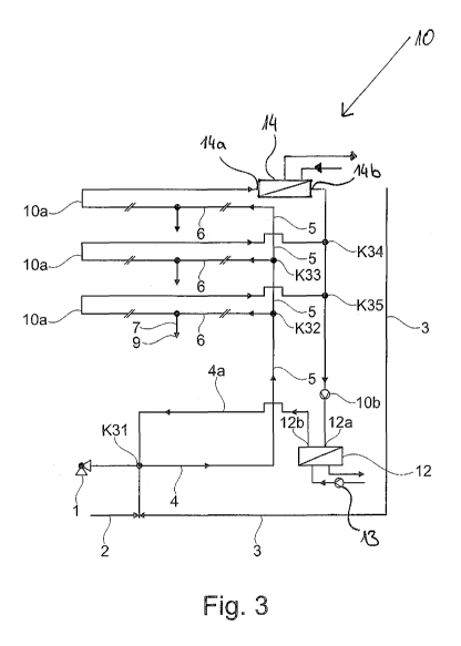
Figure 3 shows another system with nodes K31 to K34, but here the circulation
conduits 10a
emptying into the nodes K34 and K35 are led in parallel with the building
floor lines 6 departing
from the nodes K32 and K33.
Moreover, an optional decentralized cooling device 14 with an input port 14a
and an output port
14b is arranged in the uppermost building floor line 6, while to simplify the
representation the
existing junctions of a cold-side circuit and a corresponding pump are not
shown.
Similarly, further decentralized cooling devices can be arranged in the other
building floor lines.
In another embodiment similar to Figure 3, the heat exchanger 12 may be
omitted; in this case,
one cooling device 14 or multiple cooling devices 14 are necessary.
Similar to the embodiment of Figure 3, cooling devices can be provided in the
riser pipes 5 and
the building floor line of the embodiments of Figures 1, 2 and 4 to 8.
Figure 4 shows a system with nodes K41 to K51 as in Figure 3, but loop lines 8
are provided in
the building floor lines.
Figure 5 shows a system with nodes K51 to K55, in which circulation conduits
10 are led in
parallel with the riser pipes 5 connected to the nodes K52, K53.
Figure 6 shows a system with the nodes K61 to K69b, where loop lines are
provided between the
nodes K63, K64, K66, K67 and K68, K69.
Figure 7 shows a system with the nodes K71 to K75, where riser pipes 5 are
connected to the
nodes K72 and K73.
Figure 8 shows a system with nodes K81 to K89b similar to Figure 7, but with
loop lines
arranged between the nodes K89a, K89b, K88, K89 and K84 and K85.
The embodiments represented in the clean drawings under Figures 1, 3, 5, 7 can
also allow only
partial regions to have a circulation. Thus, the partial sections may also
represent installations in
dwellings, for example, which are not permitted to circulate together on
account of different
- 18 -
Date Recue/Date Received 2020-11-12
CA 03100102 2020-11-12
requirements (account metering of the water consumption). A water exchanging
to maintain the
desired temperature could be possible here with automatic flushing.
The method according to the invention is implemented in the systems of Figures
1 to 8 in the
above-described manner: starting from a temperature start value TmA* < Lon and
a volume flow
start value Vz* for the first partial section connected to the output port
(12b), a temperature
change of the water between the initial region and the end region is
determined according to a
model of the temperature change.
Moreover, a temperature change of the water between the initial region and the
end region for
each further given partial section is determined according to the model of the
temperature
change, under the boundary condition that the water temperature in the initial
region of the given
partial section is equal to the water temperature in the end region of the
partial section to which
the given partial section is connected.
Preferably, one uses the above-described model of the axial temperature
change, according to
which the water temperature TmE in the end region of a partial section of
length L is calculated
by the formula
T NTE ¨ iLufd *e E*L iLuft
icR icR
pm V M pm
The value T. of the water temperature and the value Vz of the volume flow at
the output port 12b
are chosen such that, in the end region of each partial section of the
circulation system, the water
temperature is TME < Tson and at the input port 12a the water temperature is
Tb < Tsoll with Tsoll -
Tb < 0, where 0>0 is a predetermined value.
It is understood that the circulation pump 10b is not always operated with a
constant volume
flow, i.e., regardless of whether the port inlet temperature 12a has exactly
the setpoint value or
even lies below it.
If the port inlet temperature 12a for various reasons should lie at 17 C for
example, where a
max. of 20 C is given, the delivery volume flow of the circulation pump 10b
could be reduced.
This can be done automatically, for example, under temperature control. As a
result, energy
savings will be achieved.
- 19 -
Date Recue/Date Received 2020-11-12
CA 03100102 2020-11-12
Likewise, in such a case the delivery volume flow of the pump 13 can be
reduced by temperature
control.
If the port inlet temperature for various reasons should lie at 17 C for
example (where a max. of
20 C is given for example), the flow temperature in the refrigeration circuit
could likewise be
adjusted. As a result, energy savings would be achieved.
Table 1
Symbol Unit Designation Explanation
cw kl(kg K) Specific heat capacity of the Heat for the heating of 1 kg
of
kg/m3 Quotient of mass and volume of
Density of the water
water at given temperature
Heat loss of a 1 m2 surface for a
aa W(m 2 K) Outward heat transmission temperature difference between the
coefficient surface and air of 1 K
AD W(m K) Thermal conductivity of the
AR W(m K) Thermal conductivity of the
Theinial conductivity of a
Ages W(m K)
structural piece, here a pipeline
incl. multilay ered insulation
1 (m K)W
s¨ Thermal resistance
Ages
1 (m K)W
Heat transition resistance
UR
Heat loss of a 1 m long insulated
W(m K) Heat transfer coefficient for the hot water pipe at a temperature
UR pipe difference between the water and
the air of 1 K
- 20 -
Date Recue/Date Received 2020-11-12
CA 03100102 2020-11-12
d, mm Pipe outer diameter Outer diameter of a hot water line
mm Outer diameter of an insulated hot
Pipe outer diameter
water line
Pipeline length Length of a partial section
19Luft C Air/surrounding temperature
Temperature difference between
6,19a Starting temperature difference surroundings and medium at the
start of a partial section
C Temperature of a medium at the
aMA Medium temperature at start
start of a partial section
C Temperature of a medium at
a ME Medium temperature at end
the end of a partial section
- 21 -
Date Recue/Date Received 2020-11-12
CA 03100102 2020-11-12
List of reference numbers
1 Connection to a water supply network
2 Connection line
3 Consumer line
4 Collective feed line
Riser (down pipe)
6 Building floor line
7 Single supply line
8 Loop line
8a Static or dynamic flow division
9 Tapping point
Circulation system
10a Circulation conduit
10b Circulation pump
12 Cooling device
12a Input port
12b Output port
14 Heat exchanger
14a Input port
14b Output port
- 22 -
Date Recue/Date Received 2020-11-12