Note: Descriptions are shown in the official language in which they were submitted.
CA 03100255 2020-11-19
CA Application
Blakes Ref: 24802/00001
METHOD AND DEVICE FOR CONVERTING TWO-DIMENSIONAL IMAGE INTO
THREE-DIMENSIONAL IMAGE AND THREE-DIMENSIONAL IMAGING SYSTEM
FIELD OF THE PRESENT DISCLOSURE
[0001] The present disclosure relates to a field of image processing
technology, in
particular to a method and a device for converting a two-dimensional (2D)
image into a
three-dimensional (3D) image and a 3D imaging system.
BACKGROUND OF THE PRESENT DISCLOSURE
[0002] Stereoscopic vision means when an object is viewed through both eyes by
human, a sense, of the thickness of the viewed objects and the depth or
distance of
space and the like, may arise subjectively. The main reason is that the images
of the
same viewed object on the retinas of both eyes are not exactly identical,
where the left
eye sees more left side of the object from the left while the right eye sees
more right
side of the object from the right; and a stereoscopic image of the object is
generated
after the image information from both eyes is processed through a senior
visual center.
[0003] With the development of display technology and digital technology, it
has
become a research hotspot to imitate the stereoscopic vision of human eyes by
the use
of electronic products. In the prior art, users may view a 3D image only if a
3D camera
device is adopted. Most of the existing 3D camera devices operate by imitating
the
structure of human eyes, each of which comprises two cameras, wherein an image
acquired by one of the cameras corresponds to a left-eye image for human eyes,
and
1
24012723.1
Date Recue/Date Received 2020-11-19
CA 03100255 2020-11-19
CA Application
Blakes Ref: 24802/00001
an image acquired by the other of the cameras corresponds to a right-eye image
for
human eyes; and then, the left-eye image and the right-eye image may be
synthesized
by image processing means to form the 3D image.
[0004] In the prior art, when the 3D camera device is utilized to acquire the
image, two
polarizers with polarization directions perpendicular to each other are
generally
arranged in front of a lens of each of the cameras to obtain images for the
left eye and
the right eye. Since each camera acquires the image only in one polarization
direction, it
results in that the resolution and definition of the whole image will be half
of the actual
image, thereby affecting the 3D imaging effect.
SUMMARY OF THE PRESENT DISCLOSURE
[0005] In view of this, embodiments of the present disclosure provide a method
and a
device for converting 2D image into 3D image and image processing means to
solve the
problem of poor 3D imaging effect.
[0006] In a first aspect, an embodiment of the present disclosure provides a
method
for converting 2D image into 3D image, wherein the method comprises the
following
steps:
[0007] acquiring 2D image to be processed;
[0008] performing perspective transformation on the 2D image to be processed
to
obtain a left-eye image and a right-eye image, respectively, wherein the
perspective
transformation refers to mapping the 2D image to be processed according to a
preset
rule;
2
24012723.1
Date Recue/Date Received 2020-11-19
CA 03100255 2020-11-19
CA Application
Blakes Ref: 24802/00001
[0009] adjusting a distance between the left-eye image and the right-eye image
according to a result of the perspective transformation; and
[0010] synthesizing the left-eye image and the right-eye image after the
distance
adjustment.
[0011] According to the embodiment of the present disclosure, binocular
parallax
images are created by performing perspective transformation on the 2D image to
be
processed to realize stereoscopic vision; the distance between the left-eye
image and
the right-eye image after perspective transformation is adjusted to form
binocular
parallax and create a convergence angle, so that the images observed by naked
eyes
are located at different depths, thus different stereoscopic effects may be
seen. That is,
the image transformation is performed on the 2D image without involving the
resolution
and definition of the image, so that the image quality of the 3D imaged image
is the
same as that of the original 2D image and the 3D imaging effect is not
affected.
[0012] In combination with the first aspect, the step of performing
perspective
transformation on the 2D image to be processed in a first implementation mode
of the
first aspect comprises:
[0013] aligning the 2D image to be processed onto an image template, and
extracting
sizes of the 2D image to be processed;
[0014] sequentially performing linear scaling on the sizes of respective sides
according to the preset rule to obtain a first image;
[0015] mirroring the first image to obtain a second image, wherein the first
image is as
the left-eye image and the second image is as the right-eye image; or, the
first image is
3
24012723.1
Date Recue/Date Received 2020-11-19
CA 03100255 2020-11-19
CA Application
Blakes Ref: 24802/00001
as the right-eye image and the second image is as the left-eye image.
[0016] According to the embodiment of the present disclosure, the 2D image is
converted into two images corresponding to the left eye and the right eye by
linear
scaling, that is, the 2D image without parallax is converted into the left-eye
image and
the right-eye image with parallax; and the conversion process involves only
the image
sizes and is irrelevant to the image quality, so the left-eye image and the
right-eye
image formed by linear scaling have the same quality as the original 2D image.
The
left-eye image and the right-eye image may be formed through the conversion
method
provided by the present embodiment of the present disclosure while ensuring
unchanged image quality.
[0017] In combination with the first implementation mode of the first aspect,
the
process of sequentially performing linear scaling on the sizes of the
respective sides in
sequence according to the preset rule in a second implementation mode of the
first
aspect comprises:
[0018] scanning the 2D image to be processed line by line; and
[0019] sequentially performing the linear scaling on respective lines of the
image.
[0020] According to the embodiment of the present disclosure, the 2D image to
be
processed are scanned line by line, i.e., the linear scaling is performed
sequentially on
each line to reduce the amount of processed data, so that the real-time
conversion of
the 2D image may be realized.
[0021] In combination with the first implementation of the first aspect, the
process of
adjusting the distance between the left-eye image and the right-eye image
according to
4
24012723.1
Date Recue/Date Received 2020-11-19
CA 03100255 2020-11-19
CA Application
Blakes Ref: 24802/00001
the result of the perspective transformation in a third implementation mode of
the first
aspect comprises:
[0022] aligning the left-eye image and the right-eye image onto the image
template at
the same time; and
[0023] translating the left-eye image or the right-eye image in a first
direction so that
the distance between the left-eye image and the right-eye image reaches a
preset
distance.
[0024] According to the embodiment of the present disclosure, the left-eye
image and
the right-eye image are formed by using the same image template; and the left-
eye
image and the right-eye image are translated to create the binocular parallax
and the
convergence angle, so that the conversion efficiency is improved.
[0025] In combination with the first aspect, the 2D image to be processed is a
frame
image in a video stream in a fourth implementation mode of the first aspect.
[0026] The method for converting 2D image into 3D image provided by the
embodiment of the present disclosure may convert a frame image in the video
stream
and a single 2D image, and has a wide application value.
[0027] In a second aspect, an embodiment of the present disclosure provides a
device
for converting 2D image into 3D image, comprising:
[0028] an acquisition module for acquiring the 2D image to be processed;
[0029] a perspective transformation module for performing perspective
transformation
on the 2D image to be processed to obtain a left-eye image and a right-eye
image,
respectively, wherein the perspective transformation refers to mapping the 2D
image to
5
24012723.1
Date Recue/Date Received 2020-11-19
CA 03100255 2020-11-19
CA Application
Blakes Ref: 24802/00001
be processed according to a preset rule;
[0030] an adjustment module for adjusting the distance between the left-eye
image
and the right-eye image according to a result of the perspective
transformation; and
[0031] a synthesis module for synthesizing the left-eye image and the right-
eye image
after the distance adjustment.
[0032] According to the embodiment of the present disclosure, binocular
parallax
images are created to realize stereoscopic vision by performing perspective
transformation on the 2D image to be processed; the distance between the left-
eye
image and the right-eye image after perspective transformation is adjusted to
form
binocular parallax and create a convergence angle, so that the images observed
by
naked eyes are located at different depths, thus different stereoscopic
effects may be
seen. That is, the image transformation is performed on the 2D image without
involving
the resolution and definition of the image, so that the image quality of the
3D imaged
image is the same as that of the original 2D image and the 3D imaging effect
is not
affected.
[0033] In combination with the second aspect, the perspective transformation
module
in a first implementation mode of the second aspect comprises:
[0034] an extraction unit for aligning the 2D image to be processed onto an
image
template and extracting sizes of the 2D image to be processed;
[0035] a linear scaling unit for sequentially performing linear scaling on the
sizes of
respective sides according to the preset rule to obtain a first image; and
[0036] a mirroring unit for mirroring the first image to obtain a second
image, wherein
6
24012723.1
Date Recue/Date Received 2020-11-19
CA 03100255 2020-11-19
CA Application
Blakes Ref: 24802/00001
the first image is as the left-eye image and the second image is as the right-
eye image;
or, the first image is as the right-eye image and the second image is as the
left-eye
image.
[0037] In a third aspect, an embodiment of the present disclosure provides
image
processing means, comprising:
[0038] a memory and a processor, which are in communication connection with
each
other, wherein computer instructions are stored in the memory; and the
processor
implements the method for converting 2D image into 3D image in the first
aspect or any
implementation mode of the first aspect by executing the computer
instructions.
[0039] In a fourth aspect, an embodiment of the present disclosure provides a
computer-readable storage medium, wherein the computer-readable storage medium
stores computer instructions for enabling a computer to implement the method
for
converting 2D image into 3D image in the first aspect or any implementation
mode of
the first aspect.
[0040] In a fifth aspect, an embodiment of the present disclosure provides a
3D
imaging system, comprising:
[0041] image acquisition means, having a single lens as a lens for image
acquisition;
[0042] the image processing means in the third aspect of the present
disclosure,
which is electrically connected to the image acquisition means, for converting
the 2D
image into the 3D image; and
[0043] image display means, which is electrically connected to the image
processing
means for displaying the 3D image.
7
24012723.1
Date Recue/Date Received 2020-11-19
CA 03100255 2020-11-19
CA Application
Blakes Ref: 24802/00001
[0044] In the 3D imaging system provided by the embodiment of the present
disclosure, the lens of the image acquisition means includes a single lens, so
that the
volume of the whole image acquisition means is reduced; in addition, the image
acquisition means with the single lens needs only one data line to transmit
the acquired
image, which may reduce the inner diameter of a connection line between the
image
acquisition means and the image processing means, so that the 3D imaging
system
may be applied to small human organs to perform 3D imaging on human organs,
thereby further improving the application scope of the 3D imaging system.
BRIEF DESCRIPTION OF THE DRAWINGS
[0045] The features and advantages of the present disclosure will be
understood more
clearly with reference to the accompanying drawings. The accompanying drawings
are
exemplary and should not be construed as limiting the present disclosure,
wherein
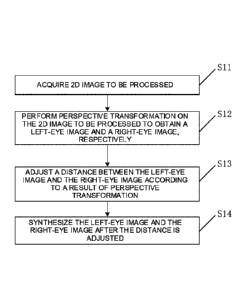
[0046] Fig. 1 shows a specific schematic flow chart for a method for
converting 2D
image into 3D image in an embodiment of the present disclosure;
[0047] Fig. 2 shows a schematic diagram illustrating a relationship between a
convergence angle and a distance between a left-eye image and a right-eye
image in
the embodiment of the present disclosure;
[0048] Fig. 3 shows another specific schematic flow chart for the method for
converting 2D image into 3D image in the embodiment of the present disclosure;
[0049] Fig. 4 shows a schematic diagram illustrating a principle of linear
scaling in an
embodiment of the present disclosure;
8
24012723.1
Date Recue/Date Received 2020-11-19
CA 03100255 2020-11-19
CA Application
Blakes Ref: 24802/00001
[0050] Fig. 5 shows another specific schematic flow chart for the method for
converting 2D image into 3D image in the embodiment of the present disclosure;
[0051] Fig. 6 shows a specific schematic structural diagram of a device for
converting
2D image into 3D image in an embodiment of the present disclosure;
[0052] Fig. 7 shows another specific schematic structural diagram of a device
for
converting 2D image into 3D image in an embodiment of the present disclosure;
[0053] Fig. 8 shows a specific schematic structural diagram of an image
processing
means in an embodiment of the present disclosure; and
[0054] Fig. 9 shows a specific schematic structural diagram of a 3D imaging
system in
an embodiment of the present disclosure.
DESCRIPTION OF THE EMBODIMENTS
[0055] To make the purposes, technical solutions and advantages of the
embodiments
of the present disclosure clearer, the technical solutions of the embodiments
of the
present disclosure will be described clearly and completely with reference to
the
accompany drawings in the embodiments of the present disclosure. Apparently,
the
described embodiments are part or not all of the embodiments of the present
disclosure.
All other embodiments obtained by those skilled in the art based on the
described
embodiments of the present disclosure without contributing creative labor
should fall
within the protection scope of the present disclosure.
[0056] According to the method for converting 2D image into 3D image,
binocular
parallax images, i.e., a left-eye image and a right-eye image, are created to
realize
9
24012723.1
Date Recue/Date Received 2020-11-19
CA 03100255 2020-11-19
CA Application
Blakes Ref: 24802/00001
stereoscopic vision by performing perspective transformation on the 2D image;
the
distance between the left-eye image and the right-eye image is adjusted to
create a
convergence angle; and a 3D image may be formed by utilizing the binocular
parallax
images in combination with the convergence angle.
[0057] An embodiment of the present disclosure provides a method for
converting 2D
image into 3D image, as shown in Fig. 1, comprising the following steps:
[0058] S11, acquiring 2D image to be processed;
[0059] The 2D image to be processed acquired by a device for converting 2D
image
into 3D image may be a 2D picture, may also be a frame image in a video
stream, and
may also be obtained by acquiring videos in real time and extracting each
frame of
images from the videos, as long as it may be ensured that the device for
converting 2D
image into 3D image may acquire the 2D image to be processed.
[0060] S12, performing a perspective transformation on the 2D image to be
processed
to obtain a left-eye image and a right-eye image, respectively.
[0061] The perspective transformation refers to mapping the 2D image to be
processed according to a preset rule. The device for converting 2D image into
3D image
maps the 2D image to be processed according to the preset rule, that is, the
left-eye
image and the right-eye image are formed through image processing according to
perspective transformation on the basis of the 2D image to be processed. The
preset
rule is used for representing a manner of perspective transformation, e.g., a
transformed image has a near end looking large and a far end looking small,
or, a
perspective image is calculated by a formula.
24012723.1
Date Recue/Date Received 2020-11-19
CA 03100255 2020-11-19
CA Application
Blakes Ref: 24802/00001
[0062] S13, adjusting a distance between the left-eye image and the right-eye
image
according to a result of perspective transformation;
[0063] The device for converting 2D image into 3D image adjusts the distance
between the left-eye image and the right-eye image formed after perspective
transformation, for creating a convergence angle.
[0064] Through many experiments, the inventor found that the corresponding
convergence angle is changed as the distance between the images is changed.
For
example, as shown in Fig. 2, the relationship between the convergence angle
and the
distance between the left-eye image and the right-eye image is described. As
shown in
Fig. 2a), when the convergence angle is al, the distance between the left eye
and the
right eye is relatively small; and as shown in Fig. 2b), when the convergence
angle is a2,
the distance between the left eye and the right eye is relatively large. In
other words,
with the change of the distance between the left eye and the right eye, the
convergence
angle will change accordingly. Therefore, the convergence angle is created by
adjusting
the distance between the left eye and the right eye in the present disclosure.
[0065] S14, synthesizing the left-eye image and the right-eye image after the
distance
adjustment;
[0066] The device for converting 2D image into 3D image synthesizes the left-
eye
image and right-eye image after adjustment, that is, by use of the binocular
parallax
created through image transformation and the convergence angle, the left-eye
image
and the right-eye image after the distance adjustment are synthesized and then
outputted to an image display means for subsequent 3D image display. The
subsequent
11
24012723.1
Date Recue/Date Received 2020-11-19
CA 03100255 2020-11-19
CA Application
Blakes Ref: 24802/00001
image display means may adjust polarization directions of the left-eye image
and the
right-eye image to make the polarization directions of the two images
perpendicular to
each other, so that the user may view a 3D image by wearing 3D glasses when
being in
use.The other ways may also be used for adjusting the polarization directions,
as long
as the polarization directions of the two images, which are viewed through
both eyes of
a person, respectively, are perpendicular to each other.
[0067] According to the embodiment of the present disclosure, binocular
parallax
images are created to realize stereoscopic vision by performing perspective
transformation on the 2D image to be processed. Furthermore, the distance
between
the left-eye image and the right-eye image after perspective transformation is
adjusted
to form binocular parallax and create the convergence angle, so that the
images
observed by naked eyes are located at different depths, thus different
stereoscopic
effects may be seen. In other words, the image transformation is performed on
the 2D
image without involving the resolution and definition of the image, so that
the image
quality of the 3D imaged image is the same as that of the original 2D image
and the 3D
imaging effect is not affected.
[0068] An embodiment of the present disclosure also provides a method for
converting
2D image into 3D image, as shown in Fig. 3, wherein the method comprises the
following steps:
[0069] S21, acquiring 2D image to be processed;
[0070] The 2D image to be processed in the present embodiment is a frame image
in
a video stream, wherein a device for converting 2D image into 3D image
sequentially
12
24012723.1
Date Recue/Date Received 2020-11-19
CA 03100255 2020-11-19
CA Application
Blakes Ref: 24802/00001
extracts each frame of images, as the 2D image to be processed, from the video
stream . Therefore, the method provided in the present embodiment may convert
the
video stream acquired by the device into a 3D video in real time.
[0071] S22, performing perspective transformation on the 2D image to be
processed
to obtain a left-eye image and a right-eye image, respectively;
[0072] The perspective transformation refers to mapping the 2D image to be
processed according to a preset rule. The device for converting 2D image into
3D image
in the present embodiment is provided with an image template for normalizing
the 2D
image to be processed.
[0073] Specifically, the step S22 comprises the following steps:
[0074] S221, aligning the 2D image to be processed onto the image template,
and
extracting sizes of the 2D image to be processed;
[0075] after acquiring the 2D image to be processed, the device for converting
2D
image into 3D image aligns the 2D image to be processed onto the image
template, and
performs uniform scaling on the 2D image to be processed to ensure that the 2D
image
to be processed do not exceed a scope of the image template.
[0076] after aligning the 2D image to be processed onto the image template,
the sizes
of the 2D image to be processed are extracted, for representing the sizes of
the
respective sides of the 2D image to be processed.
[0077] S222, performing linear scaling on the sizes in sequence according to
the
preset rule to obtain a first image;
[0078] The principle of linear scaling is shown as in Fig. 4. The perspective
13
24012723.1
Date Recue/Date Received 2020-11-19
CA 03100255 2020-11-19
CA Application
Blakes Ref: 24802/00001
transformation comprises: by a left side of an original image as a rotating
axis, turning,
inwards a screen, the original image at a certain angle, and turning, outwards
the
screen, the original image at the same angle, so as to form a middle image and
a
rightmost image in Fig. 4, respectively. In the present embodiment, the 2D
image to be
processed is performed linear scaling in sizes so that the scaled left-eye
image and
right-eye image reach an effect as shown in Fig. 4, which specifically
comprises the
following steps:
[0079] 1) scanning the 2D image to be processed line by line;
[0080] The device for converting 2D image into 3D image scans the 2D image to
be
processed aligned onto the image template line by line to obtain the sizes of
the
respective lines of the 2D image to be processed.
[0081] 2) sequentially performing linear scaling on the respective lines of
image;
[0082] The device for converting 2D image into 3D image performs linear
scaling on
the sizes of the respective lines of the 2D image to be processed according to
a
principle that one end looks large and the other end looks small, so as to
obtain a scaled
first image. The amount of processed data are reduced by performing
sequentially the
linear scaling on the respective lines, so that the real-time conversion of
the 2D image
may be realized.
[0083] S223, mirroring the first image to obtain a second image.
[0084] The device for converting 2D image into 3D image mirrors the first
image to
obtain the second image, that is, the first image is mirrored in a vertical
direction to
obtain the second image.
14
24012723.1
Date Recue/Date Received 2020-11-19
CA 03100255 2020-11-19
CA Application
Blakes Ref: 24802/00001
[0085] The first image is the left-eye image and the second image is the right-
eye
image; or, the first image is the right-eye image and the second image is the
left-eye
image.
[0086] S23, adjusting the distance between the left-eye image and the right-
eye image
according to a result of perspective transformation;
[0087] The device for converting 2D image into 3D image adjusts the distance
between the left-eye image and the right-eye image after forming the left-eye
image and
the right-eye image and superposing the left-eye image and the right-eye
image, so as
to cause double visions of the two images.
[0088] S24, synthesizing the left-eye image and the right-eye image after the
distance
adjustment;
[0089] The device for converting 2D image into 3D image re-superposes the
double
visions of the left-eye image and the right-eye image after the distance
adjustment, for
displaying the 3D image on the image display means.
[0090] In the present embodiment, compared with the method for converting 2D
image
into 3D image in the embodiment shown in Fig. 1, the 2D image is converted
into two
images corresponding to the left eye and the right eye through linear scaling
the 2D
image, that is, the 2D image without parallax is converted into the left-eye
image and
the right-eye image with parallax, wherein the conversion process only
involves the
image sizes and is irrelevant to the image quality, so the left-eye image and
the
right-eye image formed by linear scaling have the same quality as the original
2D image.
The left-eye image and the right-eye image may be formed through the
conversion
24012723.1
Date Recue/Date Received 2020-11-19
CA 03100255 2020-11-19
CA Application
Blakes Ref: 24802/00001
method provided by the present embodiment of the present disclosure while
ensuring
unchanged image quality.
[0091] A further method for converting 2D image into 3D image is also provided
according to an embodiment of the present disclosure. As shown in Fig. 5, the
method
comprises the following steps:
[0092] S31, acquiring 2D image to be processed, which is the same as S21 in
the
embodiment shown in Fig. 3 and thus will not be repeated here.
[0093] S32, performing perspective transformation on the 2D image to be
processed
to obtain a left-eye image and a right-eye image, respectively, which is the
same as S22
in the embodiment shown in Fig. 3 and thus will not be repeated here.
[0094] S33, adjusting a distance between the left-eye image and the right-eye
image
according to a result of perspective transformation.
[0095] In the present embodiment, the distance between the left-eye image and
the
right-eye image is adjusted by using an image template for normalizing the 2D
image to
be processed, which specifically comprises the following steps:
[0096] S331, aligning the left-eye image and the right-eye image onto the
image
template simultaneously;
[0097] The device for converting 2D image into 3D image simultaneously aligns
the
left-eye image and the right-eye image onto the image template, i.e., the left-
eye image
and the right-eye image are translated based on the image template, which may
ensure
better translation effect and improve the conversion efficiency of the 2D
image without
increasing the amount of processed data.
16
24012723.1
Date Recue/Date Received 2020-11-19
CA 03100255 2020-11-19
CA Application
Blakes Ref: 24802/00001
[0098] S332, translating the left-eye image or the right-eye image in the
first direction
so that the distance between the left-eye image and the right-eye image
reaches a
preset distance.
[0099] In the present embodiment, the first direction is a horizontal
direction, and one
of the left-eye image and the right-eye image aligned onto the image template
is
translated in the horizontal direction or both of the left-eye image and the
right-eye
image are simultaneously moved in opposite directions, so that the distance
between
the left-eye image and the right-eye image reaches a preset distance, wherein
the
preset distance may be specifically set according to a size of the actual
display means.
[00100] S34, synthesizing the left-eye image and the right-eye image after the
distance
adjustment, which is the same as S24 in the embodiment shown in Fig. 3 and
thus will
not be repeated here.
[00101] In the present embodiment, compared with the method for converting 2D
image
into 3D image in the embodiment as shown in Fig. 3, the left-eye image and the
.. right-eye image are formed by using the same image template; and the left-
eye image
and the right-eye image are translated to create the binocular parallax and
the
convergence angle, thereby improving the conversion efficiency.
[00102] An embodiment of the present disclosure also provides a device for
converting
2D image into 3D image. As shown in Fig. 6, the device comprises:
.. [00103] an acquisition module 41 for acquiring 2D image to be processed;
[00104] a perspective transformation module 42 for performing perspective
transformation on the 2D image to be processed to obtain a left-eye image and
a
17
24012723.1
Date Recue/Date Received 2020-11-19
CA 03100255 2020-11-19
CA Application
Blakes Ref: 24802/00001
right-eye image, respectively, wherein the perspective transformation refers
to mapping
the 2D image to be processed according to a preset rule;
[00105] an adjustment module 43 for adjusting a distance between the left-eye
image
and the right-eye image according to a result of perspective transformation;
and
[00106] a synthesis module 44 for synthesizing the left-eye image and the
right-eye
image after the distance adjustment.
[00107] According to the device for converting 2D image into 3D image provided
by the
embodiment of the present disclosure, binocular parallax images are created to
realize
stereoscopic vision by performing perspective transformation on the 2D image
to be
processed; the distance between the left-eye image and the right-eye image
after
perspective transformation is adjusted to form binocular parallax and create a
convergence angle, so that the images observed by naked eyes are located at
different
depths, thus different stereoscopic effects may be seen. In other words, the
image
transformation is performed on the 2D image without involving the resolution
and
definition of the image, so that the image quality of the 3D imaged image is
the same as
that of the original 2D image and the 3D imaging effect is not affected.
[00108] In some optional implementation modes of the present embodiment, as
shown
in Fig. 7, the perspective transformation module 42 comprises:
[00109] an extraction unit 421 for aligning the 2D image to be processed onto
the image
template and extracting the sizes of the 2D image to be processed;
[00110] a linear scaling unit 422 for sequentially performing linear scaling
on the sizes
according to a preset rule to obtain a first image; and
18
24012723.1
Date Recue/Date Received 2020-11-19
CA 03100255 2020-11-19
CA Application
Blakes Ref: 24802/00001
[00111] a mirroring unit 423 for mirroring the first image to obtain a second
image,
wherein the first image is the left-eye image and the second image is the
right-eye
image; or, the first image is the right-eye image and the second image is the
left-eye
image.
[00112] An embodiment of the present disclosure also provides image processing
means. As shown in Fig. 8, the image processing means may comprise a processor
51
and a memory 52, wherein the processor 51 and the memory 52 may be connected
through a bus or other ways, e.g., through the bus in Fig. 8.
[00113] The processor 51 may be a Central Processing Unit (CPU). The processor
51
may also be other general-purpose processors, Digital Signal Processor (DSPs),
application specific integrated circuits (ASICs), Field-Programmable Gate
Arrays
(FPGAs) or other programmable logic devices, discrete gate or transistor logic
devices,
discrete hardware components and other chips, or a combination of the above
chips.
[00114] As a non-transient computer-readable storage medium, the memory 52 may
be
used for storing non-transient software programs, non-transient computer-
executable
programs and modules, such as program instructions/modules (such as the
acquisition
module 41, the perspective transformation module 42, the adjustment module 43
and
the synthesis module 44 shown in Fig. 6) corresponding to the method for
converting 2D
image into 3D image in the embodiment of the present disclosure. The processor
51
executes various functional applications and data processing of the processor
by
running non-transient software programs, instructions and modules stored in
the
memory 52, that is, the method for converting 2D image into 3D image in the
above
19
24012723.1
Date Recue/Date Received 2020-11-19
CA 03100255 2020-11-19
CA Application
Blakes Ref: 24802/00001
embodiment of method is implemented.
[00115] The memory 52 may comprise a program memory area and a data memory
area, wherein the program memory area may store application programs required
for
operating the system and at least one function; and the data memory area may
store
data created by the processor 51. In addition, the memory 52 may include a
high-speed
random access memory, and may also include a non-transient memory, such as at
least
one disk memory device, a flash memory device or other non-transient solid-
state
memory devices. In some embodiments, the memory 52 may optionally include
memories remotely arranged relative to the processor 51; and these remote
memories
may be connected to the processor 51 through a network. Examples of the above
network include, but are not limited to, the Internet, intranet, local area
network, mobile
communication network and combinations thereof.
[00116] The one or more of the modules are stored in the memory 52; and when
implementing by the processor 51, the method for converting 2D image into 3D
image in
the embodiments as shown in Fig. 1, Fig. 3 and Fig. 5 is implemented.
[00117] The specific details of the above image processing means may be
understood
by referring to the corresponding descriptions and effects in the embodiments
shown in
Fig. 1, Fig. 3 and Fig. 5, and will not be repeated here.
[00118] An embodiment of the present disclosure also provides a 3D imaging
system;
and as shown in Fig. 9, the system comprises an image acquisition means 61, an
image
processing means 62 and an image display means 63.
[00119] In the image acquisition means 61, the lens for acquiring images
comprises a
24012723.1
Date Recue/Date Received 2020-11-19
CA 03100255 2020-11-19
CA Application
Blakes Ref: 24802/00001
single lens. The image processing means 62 is electrically connected to the
image
acquisition means 61, for converting the 2D image to be processed outputted by
the
image acquisition means 61 into the 3D image. The image display means 63 is
electrically connected to the image processing device 62, for displaying the
3D image
.. outputted by the image processing means 62.
[00120] In the 3D imaging system provided by the embodiment of the present
disclosure, the lens of the image acquisition means 61 comprises a single
lens, which
reduces the volume of the whole image acquisition means 61. In addition, the
image
acquisition means with a single lens needs only one data line to transmit the
acquired
image, which may reduce the inner diameter of a connection line between the
image
acquisition means 61 and the image processing means 62, so that the 3D imaging
system may be applied to the interior of smaller objects, such as human
organs, to
perform 3D imaging on the human organs, thereby further improving the
application
scope of the 3D imaging system.
[00121] Those skilled in the prior art should understand that all or part of
the processes
in the methods of the above embodiments may be completed by instructing
related
hardware through a computer program; the program may be stored in a
computer-readable storage medium, and may comprise the processes of the
embodiments of the above methods when the program is executed, wherein the
storage
medium may be a magnetic disk, optical disk, Read-Only Memory (ROM), Random
Access Memory (RAM), Flash Memory, Hard Disk Drive (HDD) or Solid-State Drive
(SSD); and the storage medium may also comprise a combination of the above
types of
21
24012723.1
Date Recue/Date Received 2020-11-19
CA 03100255 2020-11-19
CA Application
Blakes Ref: 24802/00001
memories.
[00122] The embodiments of the present disclosure are described with reference
to the
accompanying drawings, but various modifications and variations may be made by
those skilled in the art without departing from the spirits and the scope of
the present
disclosure, and such modifications and variations should fall within the scope
defined by
the appended claims.
22
24012723.1
Date Recue/Date Received 2020-11-19