Note: Descriptions are shown in the official language in which they were submitted.
CA 03100342 2020-11-13
WO 2019/222196
PCT/US2019/032193
TRACHEAL CANNULATION DEVICE
CROSS-REFERENCE TO RELATED APPLICATIONS
[0001] This Application claims priority to U.S. Provisional Applications
62/671,104 filed
May 14, 2018 and 62/752,255 filed October 29, 2018, each of which is
incorporated herein by
reference in its entirety.
BACKGROUND
[0002] Certain embodiments are directed to the field of medicine. In
particular certain
embodiments are directed to tracheal intubation devices.
[0003] Laryngoscopy can be used to assist tracheal intubation and
involves the insertion of
a laryngoscope to facilitate the visualization of the vocal cords (the
visualization phase of
tracheal intubation). This is followed by the insertion of an endotracheal
tube (ETT) through
the vocal cords (glottis) and then downward into the trachea (referred to as
the insertion and
cannulation phases of tracheal intubation, respectively). Traditionally,
direct laryngoscopy
(DL) has been employed to expose the glottis so that operators can view it
directly in order to
insert an ETT. A metallic stylet is usually placed within the ETT to promote
rigidity and
malleability in order to ease insertion. The stylet is more rigid than the ETT
and will maintain
its shape under normal loading conditions. Occasionally, during DL operators
are faced with
patients having anatomic features that make visualization of the vocal cords
difficult or
impossible. These circumstances, along with advances in fiber-optic and
digital camera
technology, have led to the development of video laryngoscopy (VL) which
employs
laryngoscopes with distal cameras or fiber-optic bundles. VL's make viewing
the glottic
aperture easier despite occasional challenging anatomic conditions or lower
operator
laryngoscopy skill levels. As a consequence, even novice operators can now
almost always
visualize the vocal cords in circumstances where it would have been previously
difficult. DL
and VL are both used in day-to-day tracheal intubation practice.
[0004] VL continues to emerge as an increasingly accessible and utilized
technique to
expose the glottis during tracheal intubation, particularly in circumstances
of anticipated
difficulty and during emergency airway management outside of the operating
room. Although
VL has made visualizing the vocal cords easier, a new challenge has emerged.
During DL the
path to ETT insertion is essentially a straight axis because the operator
exposes the route via
-1-
CA 03100342 2020-11-13
WO 2019/222196
PCT/US2019/032193
direct vision and aligns the oral, laryngeal, and tracheal axis. This usually
requires a minimal
bend of the distal portion of the stylet and ETT. However, with VL the cords
are exposed with
a camera or fiber-optic bundle located near the tip of the laryngoscope. The
resulting approach
to the vocal cords can be up to 90 degrees offset from the ETT axis of
insertion at the mouth,
in contradistinction DL, where the oral, laryngeal, and tracheal axis are
nearly aligned during
insertion and tracheal cannulation. Video laryngoscopes, particularly those
with
hyperangulated blades require a substantial curvature of the ETT and stylet.
This offset angle
and the additional skill required to insert the ETT via an indirect, 2-
dimensional video screen
view of the vocal cords makes ETT insertion into the glottis more difficult
(the insertion phase).
Furthermore, the resultant angle of the naturally downward angled trachea and
the incoming
ETT can cause the ETT to collide with the anterior portion of the trachea
impeding ETT
advancement into the trachea (the cannulation phase). Poor exposure of the
glottic aperture
with the video laryngoscope can exacerbate the problem. This difficulty
cannulating the trachea
with the ETT when using VL is a well described phenomenon.
[0005] Operators can find themselves with an adequate view of the vocal
cords, the ETT
engaged within the glottic aperture, yet are unable to advance the ETT into
the trachea. This
can occur despite the use of rigid stylets designed specifically to
accommodate the angle
required to facilitate VL intubation. Several methods have been described to
overcome this
problem, including the placement of a bougie into the trachea using VL, and
then railroading
the ETT over the bougie into the trachea - as used herein a bougie is a thin
cylinder of rubber,
plastic, metal or other material that is inserted into or through a body
passageway, such as the
esophagus, to diagnose or treat a condition, and can be used to widen a
passageway, guide
another instrument into a passageway, or dislodge an object. One method used
to overcome
failed advancement of the ETT into the trachea is to leave the ETT engaged in
the glottis,
remove the stylet, and advance a bougie down the ETT and into the trachea,
then railroad the
ETT over the bougie. Another is to pull back the stylet and clockwise rotate
and advance the
ETT so it's curvature is more aligned with tracheal descent angle. However,
these methods can
be challenging, especially for less-skilled operators. These difficulties can
lead to multiple
intubation attempts which can result in laryngeal injury and increased
complications. Overt
intubation failure can result in death or brain damage. A number of studies
have correlated the
increased risk of adverse events associated with multiple intubation attempts
(Mort, Anesthesia
and Analgesia. 2004; 99:607-13).
[0006] There remains a need for additional devices to better facilitate
the insertion of ETTs.
-2-
CA 03100342 2020-11-13
WO 2019/222196
PCT/US2019/032193
SUMMARY
[0007] The device described herein provides a scientific, anatomic-based
solution to a well
characterized clinical problem (the failure of tracheal intubation due to
glottic insertion and
tracheal cannulation issues). Currently, no devices approach this problem in a
similar manner
or with a similar design providing for directing an integrated bougie smoothly
down the trachea
avoiding or minimizing collision into the anterior tracheal rings and then
cannulating the
trachea with the ETT down the integrated bougie guide continuously using
primarily one hand.
[0008] Certain embodiments are directed to a tracheal cannulation device
comprising: a
curved, stylet comprising a proximal end and distal end; a flexible bougie
positioned in the
lumen of a hollow stylet or surrounding a solid, wire stylet; a handle
attached to the proximal
end of the stylet, the handle having (i) a handle core portion forming a lumen
or opening for a
stylet or bougie to traverse the handle and at least two stop portions, finger
rests, or finger rings
projecting from the handle core portion away from the long axis of the device,
a first (posterior)
stop portion or finger rest possessing a thumb rest position in top of the
stop portion or finger
rest, (ii) an endotracheal tube (ETT) advancer portion having a proximal thumb
tab configured
to provide for applying force along the axis of the ETT advancer and ETT, and
a distal ETT
collar configured to hold and provide for advancement of the proximal end
(connector) of the
ETT, (iii) a bougie advancer portion having a proximal thumb button coupled to
the flexible
bougie configured to apply force to the bougie along the long axis of the
bougie and bougie
advancer; and a rigid hypotube traversing the handle and forming a lumen in
which or below
which the bougie is positioned and to which the stylet is attached or being
solid and attaching
to a flexible bougie distally. The ETT advancer portion can be an adjustable
two-piece ETT
advancer portion and can be made from metal or thermoplastic polymer or a
combination
thereof. The handle can further include a locking mechanism to reversibly
secure the ETT
advancer to the handle core. In certain aspects, the locking mechanism is a
detent or ratchet
mechanism. The device can further include a hollow endotracheal tube (ETT),
wherein at least
a portion of the stylet and/or bougie is capable of being contained within the
ETT, and wherein
the ETT is capable of being extended past the distal end of the stylet. The
stylet can have a
curve that is a distal curve with an angle of between 20, 30, 40, 50 and/to
60, 70, 80, 90 degrees,
including all values and ranges there between. The hypotube can be metal,
thermoplastic
polymer, or combinations of metal and thermoplastic polymer. The stylet curve
can be a distal
curve with an angle of between 10 and 90 degrees. The device can be configured
to be used for
the tracheal intubation of a humans or non-human mammals.
-3-
CA 03100342 2020-11-13
WO 2019/222196
PCT/US2019/032193
[0009] Embodiments of the invention are directed to a design/mechanism
that directs a
bougie downward into the trachea during its deployment in order to minimize or
avoid collision
of the bougie into the anterior trachea. Dynamic directionality of the bougie
can be
accomplished using a Nitinol, or similar shape memory material, wire or strip.
Nitinol is a
shape-maintaining metal, so when the bougie is deployed it bends the distal
portion downward.
[0010] Another feature can be a bougie-over-stylet design. Here, instead
of the bougie being
housed within a hollow stylet, a solid inner wire is present with a hollow
bougie covering the
wire. This allows a larger dimeter bougie. One aspect of this design is the
manner in which the
inner wire connects to the handle. The inner wire can have a bend or
attachment portion
forming and angle with respect to the long axis. In certain aspects the angle
is about 90 degrees.
The attachment portion of the inner wire can be coupled to the handle or a
hypotube. In certain
instances the handle or hypotube will have notch to receive the inner wire
attachment portion
and secure it to the handle assembly.
[0011] In certain embodiments the bougie tip will be soft and
atraumatic.
[0012] Certain embodiments are directed to a bougie comprising a proximal
end and distal
end, wherein the proximal end is configured to be coupled to a deployment
device or handle
(e.g., an ETT deployment device), and the distal end comprising a rounded tip
configured to
deploy into the trachea of a subject; and the bougie having an inner guide
that comprises a
shape memory portion that returns to a default geometry that curves away from
the curve of a
deployment device when the bougie is deployed during use. The shape memory
portion can be
1, 2, 3, 4, 5, 6, 7, 8, 9, 10, 11, 12, 13, 14, 15, 16, 17 to 18 mm in length,
including all values
and ranges there between. The shape memory portion can be titanium, nickel,
nitinol, stainless
steel alloys, niobium, zirconium, cobalt-chrome alloys, molybdenum alloys,
tungsten-rhenium
alloys and any combination thereof. In certain aspects the shape memory
portion is nitinol. The
shape memory portion or guide can be inside an exterior outer coating that
forms the surface
of the bougie.
[0013] In other embodiments a bougie can comprise a proximal end and
distal end, wherein
the proximal end is configured to be coupled to a deployment device, and the
distal end
comprising a rounded tip. The bougie can have at least two lumens, (a) a first
lumen containing
or configured to contain an inner stylet wherein the bougie is configured to
extend beyond the
stylet, and (b) a second lumen containing a shape memory guide that is
configured to extend
-4-
CA 03100342 2020-11-13
WO 2019/222196
PCT/US2019/032193
with the bougie, the shape memory guide comprising a shape memory portion that
returns to a
default geometry that curves away from the curve of the stylet when the bougie
is extended
beyond the stylet. The shape memory portion is titanium, nickel, nitinol,
stainless steel alloys,
niobium, zirconium, cobalt-chrome alloys, molybdenum alloys, tungsten-rhenium
alloys and
any combination thereof. In certain aspects the shape memory portion is
nitinol. The shape
memory guide can be a wire or a strip. A strip being substantially rectangular
or oval in cross
section (having a width longer than the height) forming a flattened strip. The
stylet can be a
rigid stylet. The stylet can deform the shape memory guide from its default
geometry. The
stylet can be an aluminum, stainless-steel, or another semi-rigid material. In
certain aspects the
stylet is a curve with an angel of between 10 and 90 degrees. In other aspects
the stylet is
capable of being bent by a user and retain its shape during use of the device
during a tracheal
intubation procedure. Any embodiment of a bougie described herein can further
comprise a
hollow endotracheal tube (ETT), wherein at least a portion of the bougie is
capable of being
contained within the ETT, and wherein the ETT is capable of being extended
past the distal
end of the bougie.
[0014] In another embodiment a bougie can have a proximal end and distal
end, wherein
the proximal end is configured to be coupled to a deployment device, and the
distal end
comprising a rounded tip configured to deploy into the trachea of a subject,
wherein the bougie
does not contain a shape memory guide but has a distal shape and/or hardness
that allow it to
deflect off of the anterior tracheal wall and progress inferiorly down the
trachea during
deployment.
[0015] Certain embodiments are directed to methods for tracheal
intubation of a subject
having a glottic aperture, vocal cords, and a trachea using any bougie as
described herein. In
certain aspects the method includes obtaining any bougie described herein with
an ETT loaded
thereon; placing the distal end of the bougie into and/or directly in front of
the glottis of the
subject; extending the bougie past the distal end of the ETT, below the
glottis of the subject,
and into the trachea; extending the ETT past the distal end of the bougie,
through or below the
vocal cords of the subject, and into the trachea; and removing the bougie from
the ETT. The
subject can be a human or non-human mammal.
[0016] Other embodiments are directed to methods for the tracheal
intubation of a subject
having a glottis and a trachea comprising: obtaining a bougie of claim 6 with
an endotracheal
tube (ETT) loaded thereon; placing the distal end of the ETT/bougie into
and/or directly in
-5-
CA 03100342 2020-11-13
WO 2019/222196
PCT/US2019/032193
front of the glottis of the subject; advancing the ETT/bougie simultaneously
through the glottis
where the memory guide-shaped bougie bends the ETT posteriorly in order to
guide it away
from the anterior trachea so it can easily descend inferiorly; and removing
the bougie from the
ETT once the ETT is positioned in the trachea. The subject can be a human or
non-human
mammal.
[0017] In other embodiments the devices described herein can be
incorporated into a sterile
cover or kit.
[0018] Other embodiments of the invention are discussed throughout this
application. Any
embodiment discussed with respect to one aspect of the invention applies to
other aspects of
the invention as well and vice versa. Each embodiment described herein is
understood to be
embodiments of the invention that are applicable to all aspects of the
invention. It is
contemplated that any embodiment discussed herein can be implemented with
respect to any
method or composition of the invention, and vice versa. Furthermore,
compositions and kits of
the invention can be used to achieve methods of the invention.
[0019] The use of the word "a" or "an" when used in conjunction with the
term "comprising"
in the claims and/or the specification may mean "one," but it is also
consistent with the meaning
of "one or more," "at least one," and "one or more than one."
[0020] Throughout this application, the term "about" is used to indicate
that a value includes
the standard deviation of error for the device or method being employed to
determine the value.
[0021] The use of the term "or" in the claims is used to mean "and/or"
unless explicitly
indicated to refer to alternatives only or the alternatives are mutually
exclusive, although the
disclosure supports a definition that refers to only alternatives and
"and/or."
[0022] As used in this specification and claim(s), the words
"comprising" (and any form of
comprising, such as "comprise" and "comprises"), "having" (and any form of
having, such as
"have" and "has"), "including" (and any form of including, such as "includes"
and "include")
or "containing" (and any form of containing, such as "contains" and "contain")
are inclusive or
open-ended and do not exclude additional, unrecited elements or method steps.
[0023] Other objects, features and advantages of the present invention
will become apparent
from the following detailed description. It should be understood, however,
that the detailed
description and the specific examples, while indicating specific embodiments
of the invention,
are given by way of illustration only, since various changes and modifications
within the spirit
-6-
CA 03100342 2020-11-13
WO 2019/222196
PCT/US2019/032193
and scope of the invention will become apparent to those skilled in the art
from this detailed
description.
DESCRIPTION OF THE DRAWINGS
[0024] The following drawings form part of the present specification and
are included to
further demonstrate certain aspects of the present invention. The invention
may be better
understood by reference to one or more of these drawings in combination with
the detailed
description of the specification embodiments presented herein.
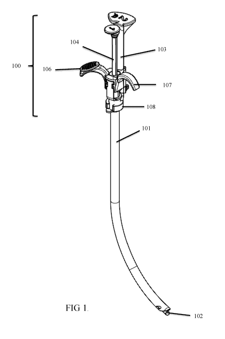
[0025] FIG. 1 is a front perspective view of tracheal cannulation device
assembly showing
the handle portion engaged with an ETT.
[0026] FIG. 2 is a backside view of tracheal cannulation device assembly
showing the
handle portion engaged with an ETT.
[0027] FIG. 3 is a top view of tracheal cannulation device assembly
showing the handle
portion engaged with an ETT.
[0028] FIG. 4 is an enlarged view of the handle.
[0029] FIG. 5 is an exploded view of one embodiment of the handle/ETT
assembly.
[0030] FIG. 6 is multiple views of one embodiment of the an ETT
advancer.
[0031] FIG. 7 is multiple views of one embodiment of the an ETT advancer
engaging an
ETT.
[0032] FIG. 8 is multiple views of one embodiment of the an ETT advancer
with a locking
mechanism (e.g., detent) engaging an ETT.
[0033] FIG. 9 shows multiple views of a handle assembly with a hypotube
and stylet
mechanism.
[0034] FIG. 10 shows multiple views of a hypotube/stylet assembly.
[0035] FIGS. 11A and 11B illustrate components of Design 2.
[0036] FIGS. 12A and 12B illustrate components of Design 4.
[0037] FIG. 13 illustrates Design 1.
[0038] FIG. 14 illustrates the operation of Design 2.
[0039] FIG. 15 further illustrates operation of Design 2.
-7-
CA 03100342 2020-11-13
WO 2019/222196
PCT/US2019/032193
[0040] FIG. 16 illustrates operation of Design 3.
[0041] FIG. 17 illustrates operation of Design 4.
[0042] FIG. 18 (A) illustrates an example of one embodiment where the
outer diameter of
the bougie and the inner diameter of the ETT are such that the gap between the
two is
minimized. Also illustrated is an example of two embodiments of the bougie,
one embodiment
having a circular cylinder shaped bougie and a second embodiment having a star
cylinder
shaped, both bougie being a double lumen bougie providing for an inner wire
and a memory
wire. (B) illustrates two separate configurations for a dual lumen bougie. A
first configuration
with the inner wire and memory wire running substantially the length of the
bougie or a second
.. configuration with inner wire at an intermediate length and the memory wire
extended to the
end of the bougie, both of which can be capped with a soft tip.
[0043] FIG. 19 illustrates the side views of one embodiment.
[0044] FIG. 20 illustrates perspective views of the embodiment of FIG.
19.
[0045] FIG. 21 illustrates two embodiments of an exploded view of the
embodiment of FIG.
19 and FIG. 20. (A) Is a size adjustable assembly with an adjustable two piece
ETT advancer
and (B) is a single size assembly with a one piece ETT advancer.
[0046] FIGs. 22A-22C illustrates certain steps in the operation of an
embodiment illustrated
in FIG. 19, FIG. 20, and FIG. 21.
DESCRIPTION
[0047] Yearly millions of people undergo tracheal intubation. Most tracheal
intubations are
performed in operating rooms by anesthesiologists or nurse anesthetists.
Direct laryngoscopy
(DL) is likely the most prominent technique. However, the routine use of video
laryngoscopy
is increasing rapidly, as VL is now present in nearly every setting where
tracheal intubation
occurs. The advent of VL has created new challenges that include occasional
difficulty
advancing the ETT into the trachea during the procedure. The ETT approach to
the trachea
during VL can be up to 90 degrees from axis of insertion at the mouth. The
resulting approach
to the vocal cords can be up to 90 degrees offset from the ETT axis of
insertion at the mouth,
in contradistinction DL, where the oral, laryngeal, and tracheal axis are
nearly aligned during
insertion and tracheal cannulation. Video laryngoscopes, particularly those
with
hyperangulated blades require a substantial curvature of the ETT and stylet.
This offset angle
and the additional skill required to insert the ETT via an indirect, 2-
dimensional video screen
-8-
CA 03100342 2020-11-13
WO 2019/222196
PCT/US2019/032193
view of the vocal cords makes ETT insertion into the glottis more difficult
(the insertion phase).
Furthermore, the resultant angle of the naturally downward angled trachea and
the incoming
ETT can cause the ETT to collide with the anterior portion of the trachea
impeding ETT
advancement into the trachea (the cannulation phase). A poor exposure of the
glottic aperture
.. with the video laryngoscope can exacerbate the problem. This difficulty
cannulating the trachea
with the ETT when using VL is a well described phenomenon. In some instances,
the device
described herein has a curved, hollow stylet or solid stylet that can
incorporate an extending or
telescoping bougie in the lumen or aroung the exterior of the stylet or
otherwise coupled to a
stylet as described herein. In some instances, this will allow the operator to
place the ETT and
stylet above or through the glottis, advance the narrow, integrated bougie
through vocal cords,
then advance the ETT over the bougie into the trachea. In some instances, the
stylet provides
the appropriate curvature in order to engage the glottic aperture or glottis
during VL, and the
bougie provides proper (tracheal) directionality for the ETT while axial force
is applied to the
ETT by the operator above. The bougie also directs the ETT downward and away
from the
anterior larynx where it can sometimes collide and hang up.
I. Intub ati on Devices
[0048] In certain embodiments, a newly described handle allows operators
to perform the
insertion phase (ETT inserted through the vocal cords) by either holding the
central portion of
the ETT or the handle (FIG. 1 and FIG. 2). The handle can comprise an ETT
advancer portion
103 (having a distal ETT collar portion 108 that engages the ETT connector), a
bougie advancer
portion 104 (operatively coupled to a bougie, stylet, or bougie and stylet
assembly that can be
positioned in the lumen of an ETT), a hypotube portion 105 (See FIG. 9 and FIG
10), at least
two stop portions or finger rests¨ a first stop portion or finger rests with a
thumb rest 106 (See
FIG. 4) and a second stop portion 107. It also allows an easy hand transition
from either hold
so the operator can perform the cannulation phase (bougie deployment followed
by ETT
advancement). This handle configuration also allows the operator to reach
higher above the
handle in order to actuate both the bougie and the ETT advancer component. As
a consequence,
a previous two-tab advancer design can be eliminated and just use one tab is
needed as a means
to adequately advance the ETT into the trachea.
[0049] FIG. 1 and FIG. 2 shows an example of a newly designed handle with
the bougie-
over-wire device assembly. FIG. 1 shows handle mechanism 100 engaged with ETT
101
having bougie 102 positioned in the lumen of ETT 101. This design allows the
operator to hold
-9-
CA 03100342 2020-11-13
WO 2019/222196
PCT/US2019/032193
ETT or handle during insertion. . FIG. 2 shows a backside view of handle
mechanism 100
engaged with ETT 101 having bougie 102 positioned in the lumen of ETT 101.
This design
allows the operator to hold ETT or handle during insertion. Operator can more
easily actuate
the bougie 104 and ETT advancer 103. This allows elimination of a bottom thumb
tab of the
ETT advancer. The design is also lower profile, allowing easier packaging and
lower
manufacturing costs. In certain instances the operator can use stop
portion/finger rest to assist
in advancement of the ETT advancer or bougie advancer by engaging the stop
portion/finger
rest 106/107 with the fingers, much like a hypodermic needle, to provide
counter force to thumb
applied force.
[0050] FIG. 3 shows a top view of the handle showing ETT advancer portion
103, a bougie
advancer portion 104, a first stop portion with a thumb rest 106 and ETT 101
visible due to
curvature. The posterior stop portion or finger rest that incorporates the
thumb rest 106 can be
offset from the axis of anterior stop portion or finger rest by 30 to 50
degrees. This allows a
more ergonomic right hand and right arm positioning by the operator during the
tracheal
.. intub ati on procedure.
[0051] FIG. 4 is an enlarged view of the handle having ETT advancer
portion 103 (having
a distal ETT collar portion 108 that engages the ETT connector and holds the
connector in a
manner whereby the ETT will not prematurely advance during bougie deployment),
a bougie
advancer portion 104 with a proximal button (operatively coupled to a bougie,
stylet, or bougie
and stylet assembly that can be positioned in the lumen of an ETT), a hypotube
portion 105
(See FIG. 9 and FIG 10), at least two stop portions or finger rests ¨ a first
stop portion with a
thumb rest 106 and a second stop portion 107. FIG 4. Also provides a view of
one embodiment
comprising locking mechanism 109, which can be in the form of a detent or
other mechanism
that can reversible lock the ETT advancer at a selected position.
[0052] FIG. 5 is an exploded view of the assembly showing various
components of one
embodiment. The components comprising ETT advancer portion 103 (having a
distal ETT
collar portion 108 that engages the ETT connector), a bougie advancer portion
not shown
(operatively coupled to a bougie 113, stylet 112, or bougie and stylet
assembly that can be
positioned in the lumen of an ETT), a hypotube portion 105, at least two stop
portions or finger
rests ¨ a first stop portion with a thumb rest 106 and a second stop portion
107. The stop portion
of the handle can be removably or integrated with handle core 110. ETT
connector 111 is
removably or intergrated with the ETT tube and is the portion that is received
by ETT collar
-10-
CA 03100342 2020-11-13
WO 2019/222196
PCT/US2019/032193
108. The hypotube portion 105 may be a rigid tube, made from any suitable
biocompatible
material known to one of ordinary skill in the art. Such materials may
include, but are not
limited to, rubber, silicon, plastics, stainless steel, metal-polymer
composites, and metal alloys
of nickel, titanium, copper cobalt, vanadium, chromium, and iron. In some
embodiments,
.. hypotube 105 may include layers of different materials and reinforcements
such as braiding or
coiling within the wall of hypotube 105.
[0053] FIG. 19 to FIG. 21 illustrates an alternative embodiment for the
device. With
reference to the exploded illustration, FIG. 21, the handle can comprise an
ETT advancer
portion 1903, either an adjustable two piece (A) or a single size one piece
(B) (having a distal
.. ETT collar portion 1908 that engages the ETT connector), a bougie advancer
portion 1904
(operatively coupled to a bougie, stylet, or bougie and stylet assembly that
can be positioned
in the lumen of an ETT), a hypotube portion 1905, at least two stop portions
or finger rests ¨ a
first stop portion or finger rests with a thumb rest 1906 and a second stop
portion 1930
configured with a loop forming a lumen providing for insertion of finger or
thumb of the
operator. It also allows an easy hand transition from either hold so the
operator can perform
the cannulation phase (bougie deployment followed by ETT advancement). The
components
comprising ETT advancer portion 1903 (having a distal ETT collar portion 1908
that engages
the ETT connector), a bougie advancer portion 1904 (operatively coupled to a
bougie 1913,
stylet 1912, and/or a memory wire 1954 or bougie 1913 and stylet 1912 and/or
memory wire
.. 1954 assembly that can be positioned in the lumen of an ETT), a hypotube
portion 1905 that
can be operatively coupled to the bougie advancer portion and the bougie
assembly, at least
two stop portions or finger rests ¨ a first stop portion with a thumb rest
1906 and a second stop
portion 1907. The stop portion of the handle can be removably or integrated
with handle core
1910. ETT connector 1911 is removably or integrated with the ETT tube and is
the portion
.. that is received by ETT collar 1908. The hypotube portion 1905 may be a
rigid tube, made
from any suitable biocompatible material known to one of ordinary skill in the
art. Such
materials may include, but are not limited to, rubber, silicon, plastics,
stainless steel, metal-
polymer composites, and metal alloys of nickel, titanium, copper cobalt,
vanadium, chromium,
and iron. In some embodiments, hypotube 1905 may include layers of different
materials and
reinforcements such as braiding or coiling within the wall of hypotube 1905.
[0054] FIG. 19 and FIG. 20 shows an assembled example of one embodiment of a
bougie-
over-wire device assembly. FIG. 19 and FIG. 20 show handle mechanism 1900
configured to
-11-
CA 03100342 2020-11-13
WO 2019/222196
PCT/US2019/032193
engaged with ETT (not shown) and having bougie 1902 configured to be
positioned in the
lumen of the ETT. This design allows the operator to hold ETT or handle during
insertion. FIG.
20 shows a perspective view of handle mechanism 1900 having a bougie 1902
positioned, the
bougie being designed to be positioned in the lumen of ETT. This design allows
the operator
to hold ETT or handle during insertion. Operator can actuate the bougie using
bougie advancer
1904 and actuate ETT advancement via ETT advancer 1903. The design is also
lower profile,
allowing easier packaging and lower manufacturing costs. In certain instances,
the operator can
use stop portion/finger rest to assist in advancement of the ETT advancer or
bougie advancer
by engaging the stop portion/finger rest 1906, 1930 with the fingers, much
like a hypodermic
needle, to provide counter force to thumb applied force.
A. ETT Advancer
[0055] With reference to FIG. 6, an ETT positioning mechanism can be
incorporated into
the ETT advancer component, such that the advancer is now comprised of
multiple parts, an
upper ETT advancer portion 120, a lower ETT advancer portion 121, ETT collar
108, and ETT
advancer locking mechanism 122. An upper subcomponent 120 interacts with the
handle, and
a lower subcomponent 121 secures to the connector of the ETT. These two
subcomponents
interact in manner that allows the lower subcomponent to move upward or
downward along
the upper subcomponent in order to align and lock in the tip of the ETT at the
appropriate
position on the distal bougie-stylet complex in the device's resting state.
The two
subcomponents will interact via a sliding locking mechanism or a linear
sliding ratcheting
mechanism that can be adjusted, locked, or unlocked by the operator. FIG. 6A
shows an
adjustable ETT Advancer in mid-position. FIG. 6B. Shows upper subcomponent 120
and FIG.
6C shows lower subcomponent 121. FIG. 6D illustrates the adjustable ETT
advancer in the
most compact position. The ETT advancer can be adjusted to accommodate ETT of
differing
lengths. In certain aspects the locking mechanism can be a ratchet mechanism
comprising a
pawl 122 that engages or disengages notches or grooves 124.
[0056] When the operator deploys the bougie, friction between the ETT
and bougie pulls
on the ETT which can pull the ETT off of the advancer collar and allow
premature advancement
of the ETT within the operational sequence. If the interaction is too loose,
the ETT slides off
prematurely. If the interaction is too tight, it becomes inordinately
difficult for the provider to
remove the ETT from the device. Through a proper combination of surface area,
material
selection, collar diameter, and collar shape ETT collar 108 will prevent the
ETT connector
-12-
CA 03100342 2020-11-13
WO 2019/222196
PCT/US2019/032193
from sliding off of the advancer prematurely during bougie deployment. FIG. 7A
shows the
ETT holder collar feature of an ETT advancer. FIG. 7B shows ETT holder collar
108 of the
ETT advancer with ETT connector 111 inserted and held securely. FIG. 7C shows
an example
of an ETT holder collar feature associated with the lower adjustable ETT
advancer portion.
[0057] In certain aspects ETT connector 101 is securely affixed to the
advancer collar 108,
the advancer itself can move downward prematurely as the operator deploys the
bougie. A
locking mechanism 123 can be used to maintain the position of the advancer
within the handle
during bougie deployment by the use of a locking mechanism (e.g., a detent
mechanism 123)
between the advancer and the handle (FIG. 8). The locking or detent mechanism
holds the
advancer in place during bougie deployment, however the mechanism is capable
of releasing
the advancer when minimal pressure applied to the advancer thumb tab by the
operator during
the ETT advancement phase. FIG 8 illustrates an example of a simple detent
mechanism (ball
type). FIG. 8A shows an ETT advancer in rest position with advancer-detent
mechanism
engaged. FIG. 8B shows an ETT advancer and detent disengaged from its resting
position
during the ETT advancement phase.
B. Bougie-Wire-Handle Interface and the Hypotube
[0058] In certain embodiments an inner stylet wire (the stylet) can be
connected to the
handle either directly or through a central clip-in mechanism (FIG. 9 and FIG.
10). The stylet
can have a proximal perpendicular bend or perpendicular inserted wire segment
or peg. This
necessitates a slot in the proximal bougie so it can slide over the wire.
Since the bougie is
already flexible, the slot further decreases its stability when an axial load
is applied by the
operator. A number of configurations of the device can be used to efficiently
transmit an axial
load to the bougie.
[0059] A partially slotted support shaft with a central channel (metal
or plastic) that extends
through the handle and connects to the bougie at some point below the handle.
This is referred
to as a hypotube 105 and can be constructed of metal or plastic. The hypotube
will be capped
with a button/thumb pad for efficient operation (FIG. 9). FIG. 9 illustrates a
solid hypotube 105
that functionally stiffens the upper portion of the bougie 102 so bougie 102
will not bend when
an axial load is applied by the operator. FIG. 9A shows a handle-bougie-
hypotube-inner wire-
handle core (clip-in) complex. FIG. 9B shows bougie-hypotube-inner wire-handle
core
complex. FIG. 9C shows a cross section of FIG. 9B demonstrating how
wire/stylet 130 can be
affixed the core of the handle 110 or handle core or clip-in. FIG. 9C also
demonstrates the
-13-
CA 03100342 2020-11-13
WO 2019/222196
PCT/US2019/032193
merger of the proximal bougie and the hypotube. The wire/stylet 130 can be
bent as shown or
have an inserted cross pin or peg. FIG. 9D-9E illustrate the hypotube 105 -
bougie 102 -inner
wire 130 complex in isolation.
[0060] A hollow, partially slotted support tube that surrounds the
proximal aspect of the
bougie and extends through the handle. This is also referred to as a hypotube
and can be
constricted of metal or plastic. In this form, the proximal aspect of the
bougie exists all of the
way to the top of the hypotube. The hypotube-bougie complex will be capped
with a
button/thumb pad for efficient operation (FIG. 10). FIG. 10 shows a hollow
hypotube 105 that
functionally stiffens the upper portion of the bougie 102 so bougie 102 will
not bend when an
axial load is applied by the operator. FIG. 10A shows a bougie 102 ¨ hypotube
105 - inner wire
130 - handle core 110 complex. FIG. 10B shows a cross section of 10A that also
demonstrates
how the wire 130 is affixed the core of the handle 110 or handle clip-in. The
wire 130 can be
bent as shown or have an inserted cross pin or peg. FIG. 10C - 10E show
hypotube 105 ¨ bougie
102 - inner wire 130 complex. Note how the hypotube fully surrounds the bougie
which is also
slotted.
[0061] In other aspects a bougie with a differential shore hardness that
is very rigid
proximally and becomes softer distally such that it does not require a
supportive hypotube can
also be used. The bougie 102 can be connected to the hypotube 105 and capped
with a button
that will be at approximately the same level of the ETT advancer 103 button
when the device
is in the resting position.
[0062] Multiple intubation attempts can lead to increased complications.
These operators
may particularly benefit from the devices described herein. Further, the
devices described
herein may provide a particular benefit to operators outside-of-the-operating
room during
emergency tracheal intubation, and in austere conditions encountered by EMS
personnel,
military medics, and critical care air transport teams.
[0063] Certain embodiments are directed to an intubation assist device
or intubation bougie
and/or stylet. Particular embodiments include, but is not required to include,
a handle as
described herein. Other aspects may be, but are not required to be combined
with the handle
design or various stylet and bougie designs described herein.
[0064] Stylets and bougies that can be used in conjunction with the handle
or a standard
handle include hollow or solid stylets or bougies. In certain aspects the
stylets can be rigid or
-14-
CA 03100342 2020-11-13
WO 2019/222196
PCT/US2019/032193
semi rigid stylets. In certain aspects the stylet is configured to be
positioned inside a lumen of
a bougie. In other aspects the bougie is configured to be positioned inside
the lumen of a hollow
stylet. In still further aspects the distal region of the stylet can be
modified. The distal region
can be modified to include a variety of tips, lights, cameras, and or other
functionalities. In
certain aspects the handle can be modified to include a video screen or
electronic monitoring
components.
[0065] The handle can include an ETT advancer component. The ETT advancer
component
being configured to moveably connect to and/or hold the ETT during insertion
as well as being
capable of applying force to advance the ETT along the long axis of the stylet
or bougie and
into the trachea. In certain aspect the ETT advancer component is moveably
connected by a
track, groove, or the like. There may or may not be a ratcheting mechanism
associated with
the interaction between the handle body and the ETT advancement component.
[0066] In certain aspects the handle can incorporate a bougie that can
be advanced to guide
insertion of the ETT. The bougie can be advanced independently of the ETT or
concurrently
with the ETT. The tip of the bougie can be soft ("safe-soft") and may or may
not be malleable
distally. The term "malleable" means that the section can be easily bent with
the fingers and
will retain its bent shape on its own without having to apply any external
retaining force.
Malleable is distinct from semi-rigid in that the amount of force needed to
bend a malleable
portion is less that than need to bend a semi-rigid portion.
[0067] In certain embodiments the handle is configured to be used with
attachable/detachable stylets or bougies, with the stylets or bougies being
disposable and the
handle being reusable. In particular aspects the handle and the stylet/bougie
are integrated and
the whole device is disposable. In particular aspects the handle and the
stylet/bougie are
integrated and the whole device is reusable. In some instances, the device is
configured to be
used by one person during a tracheal intubation of a subject in that a bougie
can be advanced
and retracted and/or an ETT can be disengaged from the stylet/bougie by using
the thumb of
the hand holding the handle. In some instances, the device is configured to be
used for tracheal
intubation of a human. In some instances, the device is configured to be used
for tracheal
intubation of a non-human mammal subject.
[0068] The intubation assist devices described herein can be configured to
be used in
conjunction with a video laryngoscopy (VL) device, a direct laryngoscopy (DL)
device, or a
-15-
CA 03100342 2020-11-13
WO 2019/222196
PCT/US2019/032193
dual purpose flexible laryngoscopy device. Each of these configurations can be
used in
conjunction with a standard straight bougie tip, a malleable bougie tip, or an
offset bougie tip.
In certain aspects the tip is flexible and bends when encountering tissue in
the larynx and
trachea. In other aspects the tip maintains a memory or shape in that once
positioned the tip
can maintain the position of shape, e.g., an offset position. In still other
aspects the tip can be
permanently formed in an offset position.
[0069] The stylet can be a curved, hollow stylet incorporating an
extendable bougie (e.g., a
Design 1 bougie) positioned in the lumen of the stylet. This device will allow
the operator to
place the ETT, utilizing the stiffness of the stylet component, at or near the
glottic aperture and
advance the integrated bougie from the stylet through the glottis and into the
trachea. Once the
bougie is in place the ETT is advanced over the bougie into the trachea. In
some instances, the
hollow stylet provides the appropriate curvature in order to engage the
glottic aperture during
VL, and the bougie provides proper (tracheal) directionality for the ETT while
force is applied
to the ETT by the operator, e.g., via an ETT advancement component. The bougie
also directs
the ETT downward and away from the anterior larynx or anterior trachea where
it can hang up
or stall.
[0070] The term "hollow stylet" as used herein includes rigid or semi-
rigid hollow stylet
configured to have a bougie passed through the lumen of the stylet. In certain
aspects a stylet
has a thin tube configuration. The hollow stylet can have an external diameter
of from 2.0,
.. 2.5, 3.0, 3.5, 4.0, 4.5, 5.0, 5.5, 6.0, 6.5, 7.0, 7.5, 8.0, 8.5, 9.0, 9.5
to 10.0 mm, including all
values and ranges there between, and an internal diameter of 1.0, 1.5, 2.0,
2.5, 3.0, 3.5, 4.0, 4.5,
5.0, 5.5, 6.0, 6.5, 7.0, 7.5, 8.0, 8.5, 9.0, to 9.5 mm, including all values
and ranges there between.
[0071] The term "stylet" as used herein includes rigid or semi-rigid
solid stylet can be
configured to be positioned inside or in the lumen of a bougie. In certain
aspects a stylet has a
circular, oval, square, rectangular or other polygonal cross-section. The
stylet can have a
diameter of from 0.5, 1.0 2.0, 2.5, 3.0, 3.5, 4.0, 4.5, 5.0, 5.5, 6.0, 6.5,
7.0, 7.5, 8.0, 8.5, 9.0, 9.5
to 10.0 mm, including all values and ranges there between.
[0072] A "bougie" is a device used as a guide to aid insertion of other
medical appliances
(e.g., ETT) via the oral cavity or other potential anatomical space or
opening. Typically, the
bougie is removed once the medical appliance is in place. The length of a
bougie can vary
from 7.5, 8.0, 8.5, 9.0, 9.5, 10.0, 10.5, 11.0, 11.5, 12.0, 12.5, 13.0, 13.5,
14.0, 14.5, 15.0, 15.5,
-16-
CA 03100342 2020-11-13
WO 2019/222196
PCT/US2019/032193
16.0, 16.5, 17.0, 17.5, 18.0, 18.5, 19.0, 19.5, 20.0, 20.5, 21.0 21.5, 22.0,
22.5, 23.0, 23.5, 24.0,
24.5, 25.0, 25.5, 26.0, 26.5, 27.0, 27.5, 28.0, 28.5, 29.0, 29.5, 30, 35, 40,
45, 50, 55, 60, 65, to
70 cm, including all values and ranges there between. Bougie outer diameters
can vary from
1.0, 1.5, 2.0, 2.5, 3.0, 3.5, 4.0, 4.5, 5.0, 5.5, 6.0, 6.5, 7.0, 7.5, 8.0,
8.5, 9.0, to 10 mm, including
all values and ranges there between. The bougie may have a circular or
elliptical cross section
and can be made of a polymer such as aliphatic polyurethane,
polytetrafluoroethylene, or other
appropriate material. In certain aspects a bougie's flexibility or flexural
modulus can changed
along its length. For example the bougie can become more flexible as you move
proximal to
distal along its length. Each section having a specific flexural modulus,
length and location
along the bougie. For example the proximal end of the bougie can be more rigid
than the distal
end. A bougie can have a durometer in a range of about 20 Shore A to about 90
Shore A, as
measured according to ASTM D2240. In certain aspects the flexible tip of a
bougie can have
a durometer from 20 shore A to 40 shore A. Other materials that can be used
for the bougie
include, but are not limited to, latex, silicon, polyester, nylon, rubber, and
silk. In certain
aspects the bougie material can comprise radiopaque or tracer material(s),
such as barium
sulphate. Specific examples of radiopaque materials include barioum
diatrizoate, ethiodized
oil, gallium citrate, iocarmic acid, iocetamic acid, iodamide, iodipamide,
iodoxamic acid,
iogulamide, iohexol, iopamidol, iopanoic acid, ioprocemic acid, iosefamic
acid, ioseric acid,
iosulamide meglumine, iosumetic acid, iotasul, iotetric acid, iothalamic acid,
iotroxic acid,
ioxaglic acid, ioxotrizoic acid, ipodate, meglumine, metrizamide, metrizoate,
propyliodone and
thallous chloride. The material may be a shape memory material and may be self-
lubricating.
[0073] In some instances, the intubation stylet contains a rigid or semi-
rigid curved, hollow
or solid stylet with a proximal end and distal end; a flexible bougie with a
handle, the bougie
contained at least partially within the lumen of the hollow stylet and
configured to be extended
from and retracted into the distal end of the hollow stylet. The bougie handle
can be configured
to extend outside of the proximal end of the hollow stylet or be inserted into
the hollow stylet
up to a predetermined stop. In other aspects a stylet handle is attached to
the proximal end of
the hollow stylet. In other instances, the intubation stylet is coupled to a
hollow endotracheal
tube (ETT), wherein at least a portion of the hollow stylet is capable of
being contained within
or inserted into the lumen of the ETT, and wherein the ETT is capable of being
extended past
the distal end of the hollow stylet. The length and dimensions of the stylet
can vary in relation
to the length and dimension of the ETT. ETT internal diameters can vary from
2.0, 2.5, 3.0,
3.5, 4.0, 4.5, 5.0, 5.5, 6.0, 6.5, 7.0, 7.5, 8.0, 8.5, 9.0, 9.5 to 10 mm,
including all values and
-17-
CA 03100342 2020-11-13
WO 2019/222196
PCT/US2019/032193
ranges there between, to accommodate patients from pre-mature infants to adult
males. The
length of an ETT can vary from 7.0, 7.5, 8.0, 8.5, 9.0, 9.5, 10.0, 10.5, 11.0,
11.5, 12.0, 12.5,
13.0, 13.5, 14.0, 14.5, 15.0, 15.5, 16.0, 16.5, 17.0, 17.5, 18.0, 18.5, 19.0,
19.5, 20.0, 20.5, 21.0
21.5, 22.0, 22.5, 23.0, 23.5, 24.0, 24.5, 25, 26, 27, 28, 29, 30, 31, 32, 33,
34 to 35 cm, including
all values and ranges there between. The internal diameter of a hollow stylet
can vary from
1.0, 1.5, 2.0, 2.5, 3.0, 3.5, 4.0, 4.5, 5.0, 5.5, 6.0, 6.5, 7.0, 7.5, 8.0,
8.5, 9.0, to 9.5 mm, including
all values and ranges there between, and an external diameter of a hollow
stylet can vary from
2.0, 2.5, 3.0, 3.5, 4.0, 4.5, 5.0, 5.5, 6.0, 6.5, 7.0, 7.5, 8.0, 8.5, 9.0, 9.5
to 10.0 mm, including all
values and ranges there between. The length of a stylet from handle to distal
end can vary form
7.0, 7.5, 8.0, 8.5, 9.0, 9.5, 10.0, 10.5, 11.0, 11.5, 12.0, 12.5, 13.0, 13.5,
14.0, 14.5, 15.0, 15.5,
16.0, 16.5, 17.0, 17.5, 18.0, 18.5, 19.0, 19.5, 20.0, 20.5, 21.0 21.5, 22.0,
22.5, 23.0, 23.5, 24.0,
24.5, 25.0, 25.5, 26, 27, 28, 29, 30, 31, 32, 33, 34, 35, 36, 37, 38, 39, 40,
41, to 42 cm, including
all values and ranges there between. In some instances, the hollow stylet
curve is a distal curve
with an angle of between about 10, 20, 30, 40, 50 and 60, 70, 80, 90, 100,
110, 120 degrees
.. over the distal 5, 6, 7, 8, 9, 10, 11, 12, 13, 14, 15, 16, 17, 18, 19, or
20 cm, including all values
and ranges there between, of the stylet. In some instances, the hollow stylet
curve is a distal
curve with an angle of about 80 degrees over the distal 5, 10, 15, or 20 cm of
the stylet. In
some instances, the hollow stylet curve is a distal curve with an angle of
between about 30 and
55 degrees over the distal 5, 10, 15, or 20 cm of the stylet. In some
instances, the hollow stylet
curve is a distal curve with an angle of 45 degrees over the distal 5, 10, 15,
or 20 cm of the
stylet. In other instances, the hollow stylet is semi-rigid in that it is
capable of being bent by a
user using his/her hands without kinking the stylet prior to insertion, yet
retain its shape during
use of the device during a tracheal intubation procedure (i.e., the stylet is
semi-rigid). In certain
aspects the degree of curvature is determined by the angle of elevation
between the long axis
and a second axis formed after the curve.
[0074] In another aspect, a method is disclosed for the tracheal
intubation of a subject using
any of the devices described herein. In some instances, the method includes
one or more steps,
such as obtaining or using any one of the tracheal intubation stylet devices
as described herein,
in certain aspects an ETT can be pre-loaded thereon; placing the distal end of
the stylet device
.. into and/or directly in front of or through the glottis of the subject;
extending a flexible bougie
past the distal end of the hollow stylet or placing the distal end of a solid
stylet, through the
vocal cords of the subject, and into the trachea; extending the ETT past the
distal end of the
stylet, through the glottis of the subject, and into the trachea; and removing
the intubation stylet
-18-
CA 03100342 2020-11-13
WO 2019/222196
PCT/US2019/032193
from the ETT. In some instances, the steps of the method are performed by one
user. In some
instances, the subject is a human. In some instances, the subject is a non-
human mammal. One
advantage to some of the intubation stylet designs described herein is that
the advancement
mechanism does not require the ETT incrementally advanced into the subglottis
and trachea
because the advance of the ETT by the mechanism allows the operator to gently
and
continuously advance the ETT into the trachea.
[0075] Certain embodiments can include a tip of contrasting color and a
soft consistency
(Safe-Soft) that prevents the ETT cuff from obscuring the operators view
during VL, provides
excellent visual acquisition of the tip, and prevents trauma to anatomic
structures; or a tip that
prevents ETT hang-up on the anterior, subglottic portion of the larynx/trachea
during
advancement of the complex into the proximal trachea.
[0076] In some instances the device includes a curved stylet comprising
a proximal end and
distal end, and a soft and flexible tip connected to the stylet, the tip
extending past the distal
end of the stylet and configured to extend past a distal end of a endotracheal
tube (ETT) loaded
on the device. In certain aspects the stylet is solid. In other aspect the
stylet is rigid, In further
aspects the stylet has a covering over the core of the solid and/or rigid
stylet that extends beyond
the distal end of the core forming a soft or pliable distal region. In other
embodiments the solid
stylet is positioned inside a lumen of a bougie or multiple lumen bougie. The
distal region can
be 1, 2, 3, 4, 5, to 5, 6, 7, 8, 9, 10 cm in length and taper into a rounded
tip. In some instances,
the distal region of the bougie or stylet is configured to extend 1 to 5
centimeters past a distal
end of an ETT loaded on the device, or extend and terminate prior to reaching
the end of the
ETT. In some instances, the tapered tip is configured to extend 3.5
centimeters past the distal
end of an ETT loaded on the device.
[0077] In some instances, the stylet or bougie is coupled to a hollow
endotracheal tube
(ETT), wherein at least a portion of the stylet or bougie is capable of being
contained within
the ETT, and wherein the ETT can be moved along the long axis of the stylet or
bougie and
extended past the distal end of the stylet or bougie during an intubation
procedure. In certain
aspects the ETT is a double lumen ETT. In other instances, the intubation
stylet or bougie is
coupled to a hollow endotracheal tube (ETT), wherein at least a portion of the
stylet or bougie
is capable of being contained within or inserted into the lumen of the ETT,
and wherein the
ETT is capable of being extended past the distal end of the stylet or bougie.
The length and
dimensions of the stylet or bougie can vary in relation to the length and
dimension of the ETT.
-19-
CA 03100342 2020-11-13
WO 2019/222196
PCT/US2019/032193
ETT internal diameters can vary from 2.0, 2.5, 3.0, 3.5, 4.0, 4.5, 5.0, 5.5,
6.0, 6.5, 7.0, 7.5, 8.0,
8.5, 9.0, 9.5 to 10 mm, including all values and ranges there between, to
accommodate patients
from pre-mature infants to adult males. The length of an ETT can vary form
7.0, 7.5, 8.0, 8.5,
9.0, 9.5, 10.0, 10.5, 11.0, 11.5, 12.0, 12.5, 13.0, 13.5, 14.0, 14.5, 15.0,
15.5, 16.0, 16.5, 17.0,
17.5, 18.0, 18.5, 19.0, 19.5, 20.0, 20.5, 21.0 21.5, 22.0, 22.5, 23.0, 23.5,
24, 25, 26, 27, 28, 29,
30, 31, 32, 32, 33, 34, 35, 36, 37, 38, 39, 40, 41, or 42 cm, including all
values and ranges there
between. The diameter of a solid stylet or bougie can vary from 1.0, 1.5, 2.0,
2.5, 3.0, 3.5, 4.0,
4.5, 5.0, 5.5, 6.0, 6.5, 7.0, 7.5, 8.0, 8.5, 9.0, to 9.5 mm, including all
values and ranges there
between. The length of a stylet or bougie from handle to distal end can vary
form 7.0, 7.5, 8.0,
8.5, 9.0, 9.5, 10.0, 10.5, 11.0, 11.5, 12.0, 12.5, 13.0, 13.5, 14.0, 14.5,
15.0, 15.5, 16.0, 16.5,
17.0, 17.5, 18.0, 18.5, 19.0, 19.5, 20.0, 20.5, 21.0 21.5, 22.0, 22.5, 23.0,
23.5, 24.0, 24.5, 25.0,
25.5, 26, 27, 28, 29, 30, 31, 32, 32, 33, 34, 35, 36, 37, 38, 39, 40, 41, or
42 cm, including all
values and ranges there between. In some instances, the stylet curve is a
distal curve with an
angle of between about 10, 20, 30, 40, 50 and 60, 70, 80, 90, 100, 110, 120
degrees over the
distal 5, 6, 7, 8, 9, 10, 11, 12, 13, 14, 15, 16, 17, 18, 19, to 20 cm,
including all values and
ranges there between, of the stylet. In some instances, the stylet curve is a
distal curve with an
angle of about 80 degrees over the distal 5, 10, or 15 centimeters of the
stylet. In some instances,
the stylet curve is a distal curve with an angle of between about 30 and 55
degrees over the
distal 5, 10, or 15 centimeters of the stylet. In some instances, the stylet
curve is a distal curve
with an angle of 45 degrees over the distal 5, 10, or 15 centimeters of the
stylet. In certain
instances, the stylet is rigid in that it is not capable of being bent by a
user using his/her hands
and retains its shape during use of the device during a tracheal intubation
procedure. In certain
instances, the stylet is malleable in that it is capable of being bent by a
user using his/her hands
yet retains its shape sufficiently during use of the device during a tracheal
intubation procedure.
In certain aspects the degree of curvature is determined by the angle of
elevation between the
long axis and a second axis formed after the curve.
[0078] In some instances, an intubation device is configured to be used
by one person during
a tracheal intubation of a subject. In some instances, the device is
configured to be used for
tracheal intubation of a human. In some instances, the device is configured to
be used for
tracheal intubation of a non-human subject.
[0079] Certain embodiments are directed to methods for tracheal
intubation of a subject
using a solid stylet. In some instances, the method includes: obtaining a
stylet or bougie device
-20-
CA 03100342 2020-11-13
WO 2019/222196
PCT/US2019/032193
disclosed herein with an ETT loaded thereon, the in certain aspects the stylet
has a distal region
that tapers to a rounded tip and placing the tapered tip through the vocal
cords and into the
trachea of the subject; advancing the distal end of the ETT through the vocal
cords of the
subject using the ETT advancer mechanism, and into the trachea. In some
instances, the steps
of the method are performed by one user. In some instances, the subject is a
human. In some
instances, the subject is a non-human.
[0080] In some instances, the device consists of a stylet or bougie
handle with a thumb
leverage point. The thumb leverage point can allow the operator to retract the
stylet or bougie
with their thumb as they advance the ETT through the vocal cords. In some
instances the stylet
handle is made of plastic and/or metal. In some instances, the hollow stylet
or multi-lumen
bougie emerges from the stylet handle and the hollow stylet is of metallic
and/or plastic
construction. In some instances, within the hollow stylet is a malleable
bougie that can be
easily advanced or retracted using a small bougie handle at the proximal end
of the bougie. In
certain aspects a stop is provided on the far proximal end of the bougie.
[0081] Non-limiting embodiments of an apparatus can include a hollow stylet
coupled to a
stylet handle and a bougie moveably coupled to the stylet. The stylet handle
can have a member
perpendicular to the long axis of stylet and a thumb leverage point that is
configured to receive
a force applied by the users thumb to separate stylet from an ETT during ETT
insertion. In one
embodiment configured for video laryngoscopy, the device has a slow, elongated
distal bend
of approximately 60, 70, to 80 degrees. Another embodiment is configured for
direct
laryngoscopy, the device that can have a shorter curved portion of
approximately 45 degrees.
Yet another embodiment is configured to enable modification of the hollow
stylet portion by
bending a distal portion of the stylet to facilitate intubation during VL or
DL. A region of the
stylet can be made from a semi-rigid material that can be bent to a desired
curvature and
maintain that curvature once bent.
[0082] Non-limiting embodiments can include a handle. An handle has a
long axis running
perpendicular to the long axis of the stylet. The device can include a stylet,
e.g., a hollow stylet
or solid wire stylet, coupled to the handle and a bougie moveably positioned
around the stylet
or in the lumen of the stylet. The handle can have at least two stop portions
or finger rests that
extend from the body of the handle. A posterior stop portion or finger rests
can have a thumb
rest that is used during the insertion phase of tracheal intubation. The thumb
rest can provide a
thumb leverage point that is configured to receive a force applied by the
users thumb during
manipulation of the device while it is being grasped around the handle/ETT
assembly. The
-21-
CA 03100342 2020-11-13
WO 2019/222196
PCT/US2019/032193
bottom of the stop portions or finger rests are configured to rest on palmar
aspect of a user's
fingers after the operator has transitioned the right hand for the cannulation
phase of tracheal
intubation which involves first deploying the bougie into the trachea and then
advancing ETT
into the trachea. The handle can be configured with an ETT advancer and bougie
advancer
mechanism. The ETT advancer is configured to engage an ETT to be advanced in
to the trachea
by providing a proximal thumb tab for advancement of the ETT using pressure
applied by the
thumb. There can be at least one thumb stop on the proximal portion of the
advancer. The distal
portion of the advancer can be configured to connect to the ETT (ETT connector
or holder
portion). In certain aspects the ETT advancer is connected by a track
configured to guide the
ETT along the stylet. There ETT advancer may be comprised of multiple sections
and there
may or may not be an adjustable ratcheting or locking mechanism associated
with the ETT
advancer. The stop portions or finger rests of the handle can be in an offset
configuration in
order to optimize handle ergonomics. The offset can be measured as an angle
formed between
the long axis of the stop portions. In certain aspects the handle can have an
optional extendable
bougie. If present, the bougie may or may not have a "safe-soft" tip and may
or may not be
malleable distally. In certain embodiment the bougie comprises a shape memory
portion.
[0083] In certain aspects, the bougie outer diameter (OD) and overall
bougie length can be
matched to different sized ETT's. The reason for this is that the inner
diameter (ID) of the
respective ETT's is to match or be compatible the OD of the bougie in order to
minimize the
gap between ETT and bougie in order to (a) avoid ETT hang up on the glottic
aperture (see
FIG. 18), and (b) to further lessen trauma and friction on the anterior
trachea during ETT
deployment, and (c) serve as an overall better guide for the ETT. From an
engineering point of
view, this will require a very low friction bougie. This will also allow more
length specific
bougies for the different sized ETT's because their overall length (OAL) is
different for each
size. However, there is fairly significant variability amongst manufacturers,
so the advance
adjustment mechanism can be used when needed. The gap will be somewhere
between 0.2, 0.3,
0.4, 0.5, 0.6, 0.7, 0.8, 0.9, 1.0, 1.1, 1.2, 1.3, 1.4, 1.5, 1.6, 1.7, 1.8,
1.9, to 2.0 mm, including all
values and ranges there between. In a particular aspect the gap is or is
between 0.5-0.7 mm.
[0084] In certain aspects, friction between the ETT and bougie can be
reduced by using
extrusions of smooth surfaced bougies (e.g., see 1852 of FIG. 18), or
longitudinal ribbed design
(e.g., see 1853 of FIG. 18). In certain aspects, bougies will be matched with
a hypotube using
an adapter segment where a hypotube will have a distal diameter to match the
OD of the bougie
-22-
CA 03100342 2020-11-13
WO 2019/222196
PCT/US2019/032193
and connect the bougie to the hypotube that can be made having either a
diameter to match the
bougie or a constant diameter that is coupled with bougies of different
diameter via the adapter.
[0085] In one embodiment the stylet can elongate to a slow, distal bend
of approximately
20, 30, 40, 45, 50, 60, 70, to 80 degrees, including all values and ranges
there between. In
.. another embodiment the stylet can be configured for direct laryngoscopy,
the device that can
have a shorter curved portion of approximately 20, 30, 40, 45, 50, 60, 70, to
80 degrees,
including all values and ranges there between. In yet another embodiment
configured to enable
modification of the hollow stylet portion by bending a distal portion of the
stylet to facilitate
intubation during VL or DL. The distal region can be made from a semi-rigid
material that can
.. be bent to a desired curvature and maintain that curvature once bent.
[0086] In various embodiments a bougie can have a "safe-soft" tip that
may or may not be
malleable distally.
[0087] In certain aspect a bougie described herein can be positioned
within or external to a
stylet and is configured to be advanced or retracted. In certain aspects the
bougie is configured
to have a stylet positioned in a lumen of the bougie. A bougie may or may not
comprise a rod
or gum elastic material which combines stiffness with flexibility at body
temperatures. In some
instances, the bougie is very soft at its most distal end having a "Safe-Soft"
tip (e.g., the distal
2, 3, 4, 5, or 6 cm of the bougie can be a soft tip). In certain embodiments
the "Safe-Soft" tip
is essentially straight or has a terminal portion that is in an offset
configuration. The soft tip
.. can minimize the possibility of airway injury during advancement of a
bougie. In some
instances, the distal end of the bougie is slightly bulbous so it cannot be
retracted fully into a
hollow stylet by the operator, nor can it be pushed back into the stylet
during the intubation
procedure. In some instances, the bougie has a small handle or stop or button
at the proximal
end that the user or an assistant can push to advance the bougie. A stop can
also serve to
.. prevent excessive advancement of the bougie into the patient or loss of the
bougie into the ETT
or the patient.
[0088] Certain embodiments of the device can be used during video
laryngoscopy. The
insertion of the ETT using a stylet can be with the assistance of a video or
direct laryngoscope.
Operator(s) can steer ETT towards the glottic aperture, direct soft-tipped
bougie and ETT tip
through the glottis, and glide bougie followed by the ETT into the trachea
with unparalleled
ease. The devices described herein can help overcome the challenge encountered
in advancing
ETT into the trachea during VL despite an adequate view of the vocal cords.
The devices can
-23-
CA 03100342 2020-11-13
WO 2019/222196
PCT/US2019/032193
also facilitate VL or DL intubation during less than optimal VL OR VL views.
Therefore,
some embodiments of the device disclosed herein can be used to facilitate
tracheal intubation
during direct laryngoscopy (DL) under less than ideal intubating conditions.
The devices
decried herein can be of particular benefit to operators outside-of-the-
operating room during
emergency tracheal intubation, and in austere conditions encountered by EMS
personnel,
military medics, and critical care air transport teams.
[0089]
In some instances, the device can be used on a human subject, a non-human
mammal
subject, or a non-mammal animal subject.
[0090]
In certain embodiments the stylet device described herein can be included in a
pre-
sterilized medical procedure kit and used for various medical procedures. In
certain aspects
sterilized procedure kits are provided with a plurality of components used in
connection with
a particular medical procedure. Certain embodiments are directed to sterilized
kits to maintain
a sterial environment or reduce the risk for infection during a procedure. Any
materials that
will be in contact with the patient can be provided in sterile compartments or
packaging that
can be opened just prior to use in order to maintain sterility or reduce
contamination.
[0091]
The stylet and bougie devices described herein can be used for VL and DL
inside or
outside the operating room setting. VL use has particularly expanded in the
settings of out-of-
the-operating room and out-of-hospital tracheal intubation.
In these settings, non-
anesthesiology personnel are usually the operators, and they have varying
degrees of airway
management skill and experience. These operators may particularly benefit from
a device like
those described herein. Therefore, the devices can be used in the operating
room, emergency
room, intensive care units, on location medial emergencies by EMS/Fire units,
military field
and air transport applications.
[0092]
Unless excluded, all elements and desctiption from each embodiment can be used
in
__ conjunction with other descirbed embodiments, e.g., element 104 can be
equivalent or similar
to 1904, etc.
Bougie Designs
[0093]
One embodiment is designated "Design 1". Design 1 includes a stylet with
steered
inner bougie having a shape memory portion. The term "shape memory" refers to
materials
capable of recovering from a deformation and returning to a default geometry.
Materials with
shape memory include, but are not limited to titanium, nickel, nitinol,
stainless steel alloys,
niobium, zirconium, cobalt-chrome alloys, molybdenum alloys, tungsten-rhenium
alloys and
-24-
CA 03100342 2020-11-13
WO 2019/222196
PCT/US2019/032193
any combinations thereof. The bougie leads, then ETT follows. Design 1 is a
bougie within a
stylet; however, Design 1 incorporates a segment or portion having shape
memory (e.g., a
curved portion that can be deformed to fit through a stylet) within the distal
portion of the
bougie. This component of the bougie may extend for its entire length but only
the distal portion
has shape memory. The shape of the shaped portion bends or is in a direction
opposite of the
stylet curve, so that as the bougie deploys it curves downward or opposite the
curve of the
stylet. In certain aspects the shaped portion of the bougie can be at most, at
least, or about 0.5,
1, 2, 3, 4, 5, 6, 7, 8, 9, 10, 11, 12, 13, 14, 15 mm in length, including all
values and ranges there
between. In other embodiments the ratio of bougie length to the shaped portion
is about 50, 45,
1
40, 35, 30, 25, 20, 15, 10, 8, 6, 4 to 1, including all ratios and ranges
there between. In certain
aspects the shaped portion can be a wire or flat strip. The diameter or cross-
sectional area of
the shaped portion can vary along its length. The shaped portion can bend at
least or about 0.5,
1, 2, 3, 4, 5, 6, 7, 8, 9, 10, 20, 30, 40, 50 degrees, including all values
and ranges there between.
[0094]
Shape memory materials include, but are not limited to titanium, nickel,
nitinol,
1
stainless steel alloys, niobium, zirconium, cobalt-chrome alloys, molybdenum
alloys, tungsten-
rhenium alloys and any combination thereof. In certain aspects the shape
memory material is
nitinol. In certain aspects the activation temperature of the nitinol can
vary, but is usually well
below that of ambient temperature such that is shape-maintaining before and
after interaction
with the patient.
2
[0095]
Referring to Figure 11A, 11 B, 14, and 15. Other embodiments are designated
"Design 2." Design 2 is a bougie-over-stylet (inner wire) design. The rigidity
and shape of the
bougie is provided by an inner wire or stylet. The stylet may be pre-formed
and rigid, or semi-
malleable in that the distal bend can be adjusted by the operator's hands, yet
the stylet maintains
shape during the tracheal intubation procedure. After insertion of the ETT &
bougie tip at or
2
into the glottis, the sequence of operation begins with shape memory material-
guided bougie
deployment into the trachea followed by ETT advancement into the trachea which
are
accomplished via separate actuators on the handle of the stylet. In certain
aspects the bougie is
a two-lumen extrusion that allows for the stylet to sit in one lumen and a
guide including a
shape memory portion ("guide") to sit in the other lumen. The shape memory
guide directs the
3
bougie to take the reverse curve during bougie deployment. This component of
the bougie may
extend for the bougie' s entire length but only the distal portion has shape
memory. The shape
memory guide is made of metal (titanium, nickel, nitinol, stainless steel
alloys, niobium,
-25-
CA 03100342 2020-11-13
WO 2019/222196
PCT/US2019/032193
zirconium, cobalt-chrome alloys, molybdenum alloys, tungsten-rhenium alloys
and any
combination thereof. In certain aspects the shape memory portion is nitinol).
The user can push
the handle actuator to deploy the bougie and shape-memory guide within the
bougie
simultaneously. At some point the shape memory guide within the bougie stops
moving due to
a stop in the handle, and the bougie continues downward into the trachea and
comes to rest in
the mid trachea (FIG 11B, 14, 15). In another version, the shape memory guide
within the
bougie continues with the bougie until the bougie comes to a stop when its
actuator button hits
the handle, and the bougie comes to rest in the mid trachea. In both versions,
the operator then
deploys the ETT over the bougie using the ETT advancer thumb tab.
[0096] Referring to FIG. 11A the bougie/stylet assembly is in its non-
deployed (resting)
state 1100. The non-deployed bougie consists of three components; the multi
lumen bougie
extruded housing with round tip 1101, the inner stylet 1102 and the shape
memory guide 1103.
Referring to FIG. 11B the bougie assembly is in its deployed state 1110. The
multi lumen
bougie 1101 extends past the inner stylet 1102 leaving a void 1104. The shape
memory guide
extends with the bougie guiding it in an opposing direction 1105 of the
original radius 1106.
[0097] Referring to FIG. 16 Certain embodiments are designated as "Design
3", which is a
bougie-over-stylet design. Bougie and ETT move together. The shape memory
guided bougie
bends and guides the ETT as both move downward together. The bougie can be a
two-lumen
extrusion that allows for the stylet to sit in one lumen and a shape memory
guide to sit in the
other lumen. The shape memory guide guides or directs the Bougie to take the
reverse curve
during bougie deployment. In certain aspects the Inner stylet is made of metal
(aluminum, steel,
etc.).
[0098] The user pushes on the handle actuator to deploy the bougie and
shape memory guide
and the ETT together. In this configuration, there is only one actuator on the
handle that deploys
the ETT and the bougie together. As in Design 2, the bougie is a two-lumen
extrusion that
allows for the stylet to sit in one lumen and a shape memory guide to sit in
the other lumen.
The shape memory guide guides or directs the bougie to take the reverse curve
during
deployment. This component of the bougie may extend for the bougie's entire
length but only
the distal portion has shape memory. At some point the shape memory guide
within the bougie
stops moving due to a stop in the handle, and the bougie continues downward
into the trachea
along with the ETT. In another version, the shape memory guide within the
bougie continues
CA 03100342 2020-11-13
WO 2019/222196
PCT/US2019/032193
with the bougie until the bougie comes to a stop when the advancer button
stops at the handle,
and the bougie & ETT come to rest simultaneously in the mid trachea.
Other embodiments are designated as "Design 4", which is a bougie-over-stylet
design. Bougie
leads then ETT follows via separate actuators on the handle. No shape memory
portion is
involved. The bougie is not guided downward. It simply bounces off the
anterior trachea
because the distal portion is soft. Referring to FIG. 12A the bougie assembly
in the un-deployed
state 1200 contains an outer single lumen bougie 1201 and an inner stylet
1202. Referring to
FIG. 12B the bougie assembly in the deployed state 1210 contains an outer
single lumen bougie
1201 and an inner stylet 1202. When deployed the inner stylet stays in its
original position and
the outer bougie advances creating a gap 1212 allowing the outer bougie 1201
to be more
malleable and move past the tracheal rings.
-27-