Note: Descriptions are shown in the official language in which they were submitted.
MULTI-GATE AND MULTI-POSITIONAL TAILGATE FOR UTILITY TASK VEHICLE
[0001]
[0002]
BACKGROUND OF THE INVENTION
[0003] A utility task vehicle (UTV) is a four-wheel drive off-road vehicle
that is
commonly referred to as a "side-by-side." A UTV typically includes a cab and a
bed for
hauling equipment and other objects. The space in the bed of a UTV is quite
limited,
which poses a challenge for a UTV user needing to haul large objects. It would
therefore be desirable to develop a tailgate for the UTV that can be converted
into
different positions depending on the needs of the user, such as when a longer
bed is
needed because longer objects are being hauled or when a taller tailgate is
needed to
maintain larger objects in the bed of the UTV.
SUMMARY
[0003a] Certain exemplary embodiments provide a multi-gate tailgate
comprising: a
first gate pivotably mountable to an end of a vehicle bed, wherein said first
gate has an
up position and a down position, wherein said first gate comprises an upper
edge; a
second gate pivotably mounted to said first gate, wherein said second gate
comprises a
plurality of locked positions relative to said first gate; and a third gate
pivotably mounted
to said second gate, wherein said third gate comprises a first locked position
relative to
said second gate and a second locked position relative to said second gate,
wherein said
third gate is stationarily positionable above said upper edge of said first
gate when said first
1
Date Regue/Date Received 2022-06-03
gate is in said up position and stationarily positionable below said upper
edge of said first
gate when said first gate is in said up position.
[0004] The present invention is directed to a multi-gate and multi-positional
tailgate for a UTV that includes a main gate pivotably mounted to an
intermediate gate
and a drop gate pivotably mounted to the intermediate gate. The intermediate
gate has
multiple locked positions and has a 270-degree range of motion relative to the
main
gate. The drop gate has multiple locked positions and has a 90-degree range of
motion
relative to the intermediate gate.
[0005] These and other features, objects and advantages of the present
invention
will become better understood from a consideration of the following detailed
description
of the preferred embodiments and appended claims in conjunction with the
drawings as
described following:
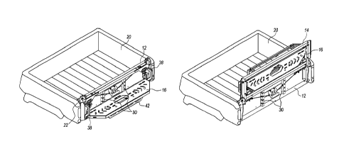
BRIEF DESCRIPTION OF THE DRAWINGS
[0006] FIG. 1 is a perspective view of the tailgate in position 1.
[0007] FIG. 2 is an end view of the tailgate in position 1.
[0008] FIG. 3 is a side view of the tailgate in position 1.
[0009] FIG. 4A is a perspective view of the inner surface of the main gate of
the
tailgate.
[0010] FIG. 48 is a perspective view of the outer surface of the main gate of
the
tailgate.
[0011] FIG. 5 is a perspective view of the intermediate gate of the tailgate.
[0012] FIG. 6 is a perspective view of the drop gate of the tailgate.
[0013] FIG. 7 is a perspective view of the tailgate in position 2.
[0014] FIG. 8 is an end view of the tailgate in position 2.
2
Date Regue/Date Received 2022-06-03
[0015] FIG. 9 is a side view of the tailgate in position 2.
[0016] FIG. 10 is a perspective view of the tailgate in position 2 with a
cooler
resting on the drop gate.
[0017] FIG. 11 is an end view of the tailgate in position 2 with a cooler
resting on
the drop gate.
[0018] FIG. 12 is a side view of the tailgate in position 2 with a cooler
resting on
the drop gate.
[0019] FIG. 13 is a perspective view of the tailgate in position 3.
[0020] FIG. 14 is an end view of the tailgate in position 3.
[0021] FIG. 15 is a side view of the tailgate in position 3.
[0022] FIG. 16 is a perspective view of the tailgate in position 4.
[0023] FIG. 17 is an end view of the tailgate in position 4.
[0024] FIG. 18 is a side view of the tailgate in position 4.
[0025] FIG. 19 is a perspective view of the tailgate in position 4 with bales
of hay
resting in the bed of the UTV.
[0026] FIG. 20 is an end view of the tailgate in position 4 with bales of hay
resting
in the bed of the UTV.
[0027] FIG. 21 is a side view of the tailgate in position 4 with bales of hay
resting
in the bed of the UTV.
[0028] FIG. 22 is a perspective view of the tailgate in position 5.
[0029] FIG. 23 is an end view of the tailgate in position 5.
[0030] FIG. 24 is a side view of the tailgate in position 5.
[0031] FIG. 25 is a perspective view of the tailgate in position 6.
3
Date Regue/Date Received 2022-06-03
[0032] FIG. 26 is an end view of the tailgate in position 6.
[0033] FIG. 27 is a side view of the tailgate in position 6.
[0034] FIG. 28 is a perspective view of the tailgate in position 7.
[0035] FIG. 29 is an end view of the tailgate in position 7.
[0036] FIG. 30 is a side view of the tailgate in position 7.
[0037] FIG. 31 is a perspective view of the tailgate in position 7 with a seat
and a
vice mounted to the main gate and a cooler resting on the drop gate.
[0038] FIG. 32 is an end view of the tailgate in position 7 with a seat and a
vice
mounted to the main gate and a cooler resting on the drop gate.
[0039] FIG. 33 is a side view of the tailgate in position 7 with a seat and a
vice
mounted to the main gate and a cooler resting on the drop gate.
[0040] FIG. 34 is a perspective view of the tailgate in position 8.
[0041] FIG. 35 is an end view of the tailgate in position 8.
[0042] FIG. 36 is a side view of the tailgate in position 8.
[0043] FIG. 37 is a perspective view of the tailgate in position 8 with 4x4
posts
resting across the bed of the UTV, the main gate, the intermediate gate, and
the drop
gate.
[0044] FIG. 38 is an end view of the tailgate in position 8 with 4x4 posts
resting
across the bed of the UTV, the main gate, the intermediate gate, and the drop
gate.
[0045] FIG. 39 is a side view of the tailgate in position 8 with 4x4 posts
resting
across the bed of the UTV, the main gate, the intermediate gate, and the drop
gate.
[0046] FIG. 40 is a perspective view of the tailgate in position 9.
[0047] FIG. 41 is an end view of the tailgate in position 9.
[0048] FIG. 42 is a side view of the tailgate in position 9.
4
Date Regue/Date Received 2022-06-03
[0049] FIG. 43 is a side view of the main gate of the tailgate.
[0050] FIG. 44 is a partial perspective view of the main gate of the tailgate.
[0051] FIG. 45 is a perspective view of the inner supports of the main gate of
the
tailgate.
[0052] FIG. 46 is a partial perspective view of the drop gate of the tailgate.
[0053] FIG. 47 is a side view of the bottle opener of the side plate of the
main gate
of the tailgate.
[0054] FIG. 48 is a partial end view of the tailgate.
[0055] FIG. 49 is a partial perspective view of the latching system for the
main
gate of the tailgate.
[0056] FIG. 50 is a partial perspective view of the latching system for the
main
gate of the tailgate.
[0057] FIG. 51 is a cross-sectional view of the latch pin of the intermediate
gate of
the tailgate.
DETAILED DESCRIPTION OF THE INVENTION
[0058] With reference to FIGS. 1-51, the preferred embodiments of the present
invention may be described. The present invention is directed to a multi-gate
and multi-
positional tailgate 10 for a UTV. As shown in FIGS. 1-6, the tailgate 10
includes a main
gate 12, an intermediate gate 14, and a drop gate 16.
[0059] The main gate 12 is pivotably mounted at the end of the bed 20 of the
UTV. The main gate 12 is preferably mounted to the UTV using the stock hinges
or
pivots of the bed 20 used for the stock tailgate of the UTV. More
specifically, the main
gate 12 includes rods 56 in the bottom corners of the main gate 12 that are
received by
the pivots in the sides of the bed 20 of the UTV. The main gate 12 includes a
latching
Date Regue/Date Received 2022-06-03
system, as shown in FIGS. 48 and 49-50. The latching system includes a handle
72 for
opening and closing the main gate 12. Two cables 74 connect the handle 72 and
latch
pins 76 that extend from the upper sides of the main gate 12. The latching
system also
includes latch block 68. The latch blocks 68 include slots 70 for receiving
the latch pins
76. The latch block 68 is a replacement for the stock tailgate closure mount
on the inside
wall of the bed 20 of the UTV. The latch pins 76 have a constant spring force
in the
outward direction. A ramp on the leading edge of the latch block 68 forces the
spring
actuated pins 76 to compress as the main gate 12 is being closed. Once the
latch pins
76 are received in the slots 70 of the latch block 68, the main gate 12 is in
the closed
position. Alternatively, the main gate 12 is secured in the closed position by
any other
type of tailgate latching system that would be well-known to one skilled in
the art.
[0060] The main gate 12 is supported by tailgate cables 18 attached between
the
bed 20 of the UTV and the main gate 12. The main gate 12 has a range of motion
0-90
degrees relative to the UTV's bed 20. Lifting up on the handle 72 opens the
main gate.
When the handle 72 is lifted, the cables 74 pull the latch pins 76 from the
slots 70 of the
latch block 68, which allows the main gate 12 to be opened or lowered by the
user.
[0061] The main gate has two side plates 22 on opposite sides of the main gate
12. The side plates include a bottle opener 24 (as shown in FIG. 47) that is
accessible in
all deployable positions of the main gate 12. The side plates 22 also include
pivots 48 to
allow the intermediate gate 14 to be pivotable mounted to the main gate. The
side plates
22 also include lock out holes 50 for securing the intermediate gate 14 into
the different
positions described below. The main gate 12 includes inner supports 30
positioned
between the sides of the main gate that provide multiple tie-off points for
securing
equipment and gear as needed. As shown in FIGS. 7-8 and 45, a hook or rope may
be
threaded through the corners of the inner supports 30. The handle 72 is
positioned
between the inner supports 30. Mounts 28 are attached to the inner panel 26 of
the main
6
Date Regue/Date Received 2022-06-03
gate 12, as shown in FIG. 44. Boat seats 54 or work devices 52 (e.g., a vice)
may be
secured to the mounts 28, as shown in FIGS. 31-33.
[0062] The intermediate gate 14 is pivotably mounted to the side plate 22 of
the main gate 12. More specifically, the rods 58 in the upper portion of the
intermediate gate 14 are received in the pivots 48 in the side plates of the
main gate
12. The intermediate gate 14 has a roughly rectangular shaped frame 32 that is
open
in the middle, as shown in FIG. 5. The intermediate gate 14 has a range of
motion of
0-270 degrees relative the main gate 12. The intermediate gate 14 includes
latch
pins 34 positioned below the rods 58 in opposite ends of the frame 32. The
latch
pins 34 engage the lockout holes 50 in the side plates 22 of the main gate 12
and
allow the intermediate gate 14 to be locked in 90-degree positions about its
270-
degree range of motion. The latch pins 34 include a spring 80 and a stop plate
82 to
maintain a constant spring force in the outward direction that force one end
of each
of the latch pins 34 to engage the lockout holes 50, as shown in FIG. 51 with
respect
to the left latch pin. The latch pins 34 must be pulled inward and held in
that position
by the user for the latch pins 34 to be disengaged from the lockout holes 50.
The
latch pin 34 is pulled inward by sliding the handle 84 of the latch pin away
from the
lockout holes 50. Alternatively, the latch pins 34 may be pulled inward by the
user
and locked in that position (also referred to as the locked open position) by
sliding
the handle away from the lockout holes 50 and into a lock notch 86. In this
event,
the user does not have to manually hold the latch pins 34 in that position. To
move
the intermediate gate 14 relative to the main gate 12 from one position to the
next
position, the user must disengage the latch pins 34 from the lockout holes 50
in the
side plates 22 of the main gate 12. The intermediate gate 14 is then rotated
or pivoted
to the desired position and the latch pins 34 are released to engage different
lockout
holes 50 than were previously engaged.
7
Date Regue/Date Received 2022-06-03
[0063] The outer surface of the intermediate gate 14 contains sockets 36 for
LED
lights for added visibility during low light or no light conditions, as shown
in FIG. 48.
Vertically-oriented handles 38 are attached to opposite sides of the
intermediate gate 14,
which may be used to orient the intermediate gate 14 at the desired position.
The
intermediate gate 14 also includes a horizontally-oriented handle 38. The
intermediate
gate 14 contains secondary latches 60 which secure the drop gate 16 in a
stored position
(or up position) while it is not in use. The intermediate gate 14 also
includes pivots 62 in
which the drop gate 16 is mounted and moves.
[0064] The drop gate 16 is pivotably mounted to the intermediate gate 14. Rods
64 positioned on opposite ends of the drop gate 16 are mounted in the pivots
62 in the
frame 32 of the intermediate gate 14. The drop gate 16 has a range of motion 0-
90
degrees relative to the intermediate gate 14. The drop gate 16 is locked in
the stored (or
closed) position by latches 60 provided in the intermediate gate 14 engaging
with slots
78 in the side surfaces of the drop gate 16. The latches 60 are preferably
twisting cam
latches. The twisting cam latches preferably include a handle at one end and a
cam at
the opposite end. The cams of the latches 60 may be locked in the slots 78 by
rotating
the handle to the locked position. To unlatch and open the drop gate 16, the
user rotates
the handle of the latches 60 to the unlocked position. In this position, the
cams may be
disengaged from the slots 78 in the drop gate 16 and the drop gate 16 may be
opened or
lowered.
[0065] When the drop gate 16 is in the stored position, it has an outer
surface
flush with the outer surface of the intermediate gate 14. As shown in FIG. 46,
the drop
gate has multiple openings 40 in the frame of the drop gate 16 to allow ice-
chests,
coolers, toolboxes, work equipment and recreational gear to be properly
secured as
needed. The outer surface of the drop gate 16 includes drain holes which allow
liquid or
sludge to drain from the interior of the drop gate, as shown in FIG. 6. An
elongated
handle 42 is attached to the outer surface of the drop gate 16.
8
Date Regue/Date Received 2022-06-03
[0066] The tailgate 10 of the present invention include nine different
positions, as
shown in FIGS. 1-3 and 7-42. In position 1, as shown in FIGS. 1-3, the main
gate 12 is
closed and latched to the bed 20 of the UTV in the upright position. The
intermediate
gate 14 and the drop gate 16 are also closed and locked. The tailgate 10 may
be
converted from position 1 to position 6 (described below) by unlatching and
opening the
main gate 12.
[0067] In position 2, as shown in FIGS. 7-12, the main gate 12 is closed and
latched to bed 20 of the UTV in the upright position. The intermediate gate 14
is closed
and latched parallel to the main gate 12. The drop gate 16 is opened downward
and
extends perpendicular to the intermediate gate 14 and the main gate 12. This
position
allows objects, such as coolers, toolboxes, gear and equipment, to be mounted
and
carried outside of the bed area while still allowing the main gate 12 to
function to access
the interior of the bed 20 as needed by the user. FIGS. 10-12 show a cooler 44
resting
on the drop gate 16.
[0068] In position 3, as shown in FIGS. 13-15, the main gate 12 is closed and
latched to the bed 20 of the UTV in the upright position. The intermediate
gate 14 is
hinged 90-degrees to the main gate 12 and locked. The drop gate 16 is latched
closed
and its outer surface is flush with the intermediate gate 14. This position
creates an
elevated horizontal surface outside of the bed 20 of the UTV that can be used
as a work
or table surface or as a storage space. The tailgate 10 may be converted from
position 3
to position 7 (described below) by opening the main gate 12.
[0069] In position 4, as shown in FIGS. 16-21, the main gate 12 is closed and
latched to the bed 20 of the UTV in the upright position. The intermediate
gate 14 is
hinged 180-degrees relative to the main gate 12. In this regard, the
intermediate gate 14
is locked and extends upward from the main gate 12. In this position, the drop
gate 16 is
closed. This position creates an extension to the bed 20 of the UTV that can
be utilized
when carrying larger objects, such as hay bales, limbs, hunting gear, or work
equipment.
9
Date Regue/Date Received 2022-06-03
FIGS. 19-21 show hay bales 46 being carried in the bed 20 of the UTV with the
tailgate
in position 4. The tailgate 10 may be converted from position 4 to position 8
(described below) by opening the main gate 12.
[0070] In position 5, as shown in FIGS. 22-24, the main gate 12 is closed and
latched to the bed 20 of the UTV in the upright position. The intermediate
gate 14 is
hinged 270-degrees relative to the main gate 12 and locked, and the drop gate
16 is
closed. Thus, the intermediate gate 14 is positioned horizontally above a
portion of the
bed 20 of the UTV. This position creates an elevated horizontal surface inside
the
perimeter of the bed 20 of the UTV that can be used for a work or table
surface or as
storage space. The tailgate may be converted from position 5 to position 9
(described
below) by opening the main gate 12.
[0071] In position 6, as shown in FIGS. 25-27, the main gate 12 is opened
downward such that the inner surface of the main gate 12 is parallel to the
bottom of the
bed 20 of the UTV. The intermediate gate 14 and the drop gate 16 are closed
and
locked. The tailgate 10 is in this position when the main gate 12 is lowered
for the user to
access the interior of the bed 20 of the UTV.
[0072] In position 7, as shown in FIGS. 28-33, the main gate 12 is opened
downward such that the inner surface of the main gate 12 is parallel to the
bottom of the
bed 20 of the UTV. The intermediate gate 14 is hinged and locked 90-degrees
relative to
the main gate 12. The drop gate 16 is opened downward and is positioned
parallel to the
main gate 12. This position allows users to access the interior of the bed 20
of the UTV,
but also allows users to add or remove seats 54 or work devices 52 from the
mounts 28.
The drop gate 16 serves as a footrest while sitting on main gate 12 in this
position.
When the latch pins 34 of the intermediate gate 14 are in the unlocked
position, the
tailgate 10 can move between position 2 and position 7 with an object (e.g.,
cooler 44)
secured to the drop gate 16. That is possible because intermediate gate 14
pivots freely
Date Regue/Date Received 2022-06-03
when the latch pins 34 are disengaged and thus the intermediate gate 14 will
remain
perpendicular to the ground even as the main gate 12 is opened or lowered.
[0073] In position 8, the main gate 12 is opened downward such that the inner
surface of the main gate 12 is parallel to the bottom of the bed 20 of the
UTV. The
intermediate gate 14 is hinged and locked 180-degrees relative to the main
gate 12, and
the drop gate 16 is closed. This position creates a horizontal extension to
the end of the
bed 20 of the UTV which allows the user to carry longer items (e.g., 4x4 posts
66, limbs,
hunting equipment and recreational gear) with more stability. This position
also extends
the standing area for accessing an overhead cargo rack that may be attached to
the
UTV. FIGS. 37-39 show 4x4 posts being carried in the bed 20 of the UTV with
the
tailgate in position 8.
[0074] In position 9, as shown in FIGS. 40-42, the main gate 12 is opened
downward such that the inner surface of the main gate 12 is parallel to the
bottom of the
bed 20 of the UTV. The intermediate gate 14 is hinged and locked 270-degrees
relative
to the main gate 12, and the drop gate 16 is closed. This position creates an
extended
contained bed area which allows the user to carry larger objects, such as dog
kennels,
hunting equipment and recreational gear, without having fasten them in place.
[0075] The present invention has been described with reference to certain
preferred and alternative embodiments that are intended to be exemplary only
and not
limiting to the full scope of the present invention as set forth in the
appended claims.
11
Date Regue/Date Received 2022-06-03