Note: Descriptions are shown in the official language in which they were submitted.
Rowand Ref: 347-0003CAP1
Specification
SYSTEM AND METHOD FOR DETECTING AIRBORNE PATHOGENS
TECHNICAL FIELD
[0001] The present application relates to air quality monitoring and, more
particularly, to systems
and methods for detecting presence of airborne pathogens in an indoor
environment.
BACKGROUND
[0002] Conventional air monitoring systems measure the particulate matter
content of air in an
indoor environment. Such systems generally do not provide specific information
identifying the
types of particles that are present in the air. In crowded indoor
environments, such as schools,
hospitals, airports, malls, etc., it is desirable to be able to detect, in
real-time, the presence of
harmful agents (e.g. pathogens) in the air, in order to prevent and/or contain
outbreaks.
BRIEF DESCRIPTION OF DRAWINGS
[0003] Reference will now be made, by way of example, to the accompanying
drawings which
show example embodiments of the present application and in which:
[0004] FIG. lA is a partial exploded view of an example air sampling system,
in accordance with
embodiments of the present disclosure;
[0005] FIG. 1B is a high-level schematic diagram of the example air sampling
system of FIG. 1A;
[0006] FIG. 2 is a partial side cross-sectional view of internal components of
the example air
sampling system of FIG. 1A;
[0007] FIG. 3 is a perspective view of an example flow column which may be
disposed inside a
collection chamber;
[0008] FIGS. 4A and 4B show side views of the example flow column of FIG. 3;
1
Date Recue/Date Received 2020-11-27
Rowand Ref: 347-0003CAP1
Specification
[0009] FIG. 5A is a sectional view of a target holder inside a collection
chamber of the example
air sampling system of FIG. 1A;
[0010] FIG. 5B is a top view of the example flow column of FIG. 5;
[0011] FIGS. 6A and 6B show side cross-sectional views of a collection chamber
of the example
air sampling system of FIG. 1A;
[0012] FIG. 6C shows a magnified view of a reaction compartment inside a
collection chamber of
the example air sampling system of FIG. 1A; and
[0013] FIG. 7 shows, in flowchart form, an example method for detecting
airborne pathogens.
[0014] Like reference numerals are used in the drawings to denote like
elements and features.
DETAILED DESCRIPTION OF EXAMPLE EMBODIMENTS
[0015] In one aspect, the present disclosure describes an air sampling system.
The air sampling
system includes: an air inflow channel having an air inlet portion at a top
end, the air inflow
channel being oriented substantially vertically; a fan configured to cause air
in a sampling
environment to flow into the air inflow channel via the inlet portion; a
cooling unit for cooling air
in the air inflow channel, the cooling unit disposed downstream of the inlet
portion; a collection
chamber for collecting liquid water condensed from air in the air inflow
channel, the collection
chamber being fluidly connected to the air inflow channel; a sensing unit for
determining a volume
of liquid in the collection chamber; and a controller configured to control
the cooling unit based
on signals generated by the sensing unit.
[0016] In some implementations, the sensing unit may be a level sensor
associated with the
collection chamber.
[0017] In some implementations, the level sensor may be a capacitive sensor.
[0018] In some implementations, the controller may be configured to control
the cooling unit
based on determining, from signals generated by the level sensor, whether a
liquid level in the
collection chamber deviates from a defined level.
2
Date Recue/Date Received 2020-11-27
Rowand Ref: 347-0003CAP1
Specification
[0019] In some implementations, the air sampling system may further include an
air outflow
channel that is fluidly connected to the collection chamber, the air outflow
channel being oriented
substantially vertically and the cooling unit may be further configured to
cool air in the air outflow
channel.
[0020] In some implementations, the cooling unit may include one or more
cooling coils disposed
downstream of the inlet portion, the one or more cooling coils being supported
in thermal contact
with at least a portion of the air inflow channel.
[0021] In some implementations, the cooling unit may include one or more cold
plates disposed
downstream of the inlet portion, the one or more cold plates being supported
in thermal contact
with at least a portion of the air inflow channel.
[0022] In some implementations, the one or more cold plates may be made of
aluminum.
[0023] In some implementations, the air sampling system may further include a
particulate
monitor device for monitoring particulate matter content of air flowing into
the air inflow channel.
[0024] In some implementations, the air sampling system may further include an
air pump for
drawing air out of the collection chamber via an air outflow channel.
[0025] In some implementations, the air pump may be a high-volume air sampling
pump.
[0026] In some implementations, the sensing unit may be a temperature sensor
for measuring a
temperature of the air in the air inflow channel and the controller may be
configured to control the
cooling unit based on measurements obtained from the temperature sensor.
[0027] In some implementations, the collection chamber may include an active
target substrate
having a surface that is coated with bioreceptors and the air sampling system
may further include
an optical detection unit that is configured to illuminate the active target
substrate with a light
source.
[0028] In some implementations, the bioreceptors may be antibodies.
[0029] In some implementations, the air sampling system may further include: a
liquid inflow
channel having a liquid inflow port, the liquid inflow channel being fluidly
connected to the
3
Date Recue/Date Received 2020-11-27
Rowand Ref: 347-0003CAP1
Specification
collection chamber; a liquid outflow channel that is fluidly connected to the
collection chamber;
and a liquid pump for causing liquid to flow into and out of the collection
chamber.
[0030] In some implementations, the sensing unit may be a flow sensor
associated with at least
one of the liquid inflow channel or the liquid outflow channel for measuring a
rate of flow of liquid
out of the collection chamber and the controller may be configured to control
the cooling unit
based on measurements obtained from the flow sensor.
[0031] In some implementations, the air sampling system may further include a
hygroscopic filter
that removes liquid from air that is expelled out of the collection chamber.
[0032] In some implementations, the collection chamber may be removably
coupled to the air
inflow channel.
[0033] In some implementations, the air sampling system may further include a
plurality of glass
beads disposed inside the collection chamber, the surfaces of the plurality of
glass beads being
exposed to liquid collected in the collection chamber.
[0034] In some implementations, the air sampling system may further include a
notification unit
for generating signals representing notifications indicating detection of one
or more target analytes
in the liquid collected in the collection chamber.
[0035] In another aspect, the present disclosure describes an air sampling
system. The air sampling
system includes: an air intake unit defining an inlet and an air inflow
channel; a fan configured to
cause air in a sampling environment to flow into the air inflow channel via
the inlet; a cooling unit
for cooling air in the air inflow channel; a collection chamber for collecting
liquid water condensed
from air in the air inflow channel, the collection chamber being removably
coupled to the air intake
unit and including an active target substrate having a surface that is coated
with bioreceptors; and
an optical detection unit including a light source, the optical detection unit
being configured to
illuminate the active target substrate with the light source.
[0036] In some implementations, the collection chamber may be coupled to the
air intake unit
using a threaded connection.
[0037] In some implementations, the light source may be an infrared light
emitter.
4
Date Recue/Date Received 2020-11-27
Rowand Ref: 347-0003CAP1
Specification
[0038] In some implementations, the air sampling system may further include a
flow column that
is centrally disposed inside the collection chamber, the flow column being
fluidly connected to the
air inflow channel and defining a plurality of apertures through which fluid
flows into the
collection chamber.
[0039] In some implementations, the air sampling system may further include a
plurality of glass
beads disposed in an annular space between the flow column and an inner wall
of the collection
chamber, the surfaces of the plurality of glass beads being exposed to liquid
that collects in the
collection chamber.
[0040] In some implementations, the collection chamber may include a plurality
of glass beads
disposed in an annular space between the flow column and an inner wall of the
collection chamber
and the surfaces of the plurality of glass beads may be exposed to liquid that
collects in the
collection chamber.
[0041] In some implementations, the collection chamber may include a permeable
stopper that
supports the plurality of glass beads above and in spaced relation to a bottom
wall of the collection
chamber, and the active target substrate may be disposed in a reaction
compartment defined by the
stopper and the bottom wall of the collection chamber.
[0042] In some implementations, the air sampling system may further include an
air outflow
channel that is fluidly connected to the collection chamber, and the cooling
unit may be further
configured to cool air in the air outflow channel.
[0043] In some implementations, the cooling unit may include one or more cold
plates disposed
downstream of the inlet, the one or more cold plates being supported in
thermal contact with at
least a portion of the air inflow channel.
[0044] In some implementations, the bioreceptors may be antibodies.
[0045] In some implementations, the air sampling system may further include: a
liquid inflow
channel having a liquid inflow port, the liquid inflow channel being fluidly
connected to the
collection chamber; a liquid outflow channel that is fluidly connected to the
collection chamber;
and a liquid pump for causing liquid to flow into and out of the collection
chamber.
Date Recue/Date Received 2020-11-27
Rowand Ref: 347-0003CAP1
Specification
[0046] In some implementations, the air sampling system may further include a
flow sensor
associated with at least one of the liquid inflow channel or the liquid
outflow channel for measuring
a rate of flow of liquid out of the collection chamber, and the cooling unit
may be controlled based
on measurements obtained from the flow sensor.
[0047] In some implementations, the air sampling system may further include a
sensing unit for
determining a volume of liquid in the collection chamber, and the cooling unit
may be controlled
based on signals generated by the sensing unit.
[0048] In some implementations, the sensing unit may be a level sensor
associated with the
collection chamber.
[0049] In some implementations, the cooling unit may be controlled based on
determining, from
signals generated by the level sensor, whether a liquid level in the
collection chamber deviates
from a defined level.
[0050] In some implementations, the optical detection unit may include optical
components for
detecting light reflected by the active target substrate and the control
parameters of the light source
may be adjustable based on a choice of the bioreceptors that are associated
with the active target
substrate.
[0051] In some implementations, the active target substrate may be resin that
is treated with the
bioreceptors.
[0052] In another aspect, the present disclosure describes a liquid collection
chamber for an air
sampling system. The liquid collection chamber includes: a container for
collecting liquid water
condensed from air that is drawn into the air sampling system, the container
being removably
coupled to an air intake unit of the air sampling system; an active target
substrate having a surface
that is coated with bioreceptors; and a target holder for holding the active
target substrate in fluid
contact with the liquid in the liquid collection chamber.
[0053] In some implementations, the liquid collection chamber may include a
flow column that is
centrally disposed inside the liquid collection chamber, the flow column being
fluidly connected
to the air intake unit and defining a plurality of apertures through which
fluid flows into the liquid
collection chamber.
6
Date Recue/Date Received 2020-11-27
Rowand Ref: 347-0003CAP1
Specification
[0054] In some implementations, the liquid collection chamber may include a
plurality of glass
beads disposed in an annular space between the flow column and an inner wall
of the liquid
collection chamber and the surfaces of the plurality of glass beads may be
exposed to liquid that
collects in the liquid collection chamber.
[0055] In some implementations, the liquid collection chamber may include a
permeable stopper
that supports the plurality of glass beads above and in spaced relation to a
bottom wall of the liquid
collection chamber, and the active target substrate may be disposed in a
reaction compartment
defined by the stopper and the bottom wall of the liquid collection chamber.
[0056] In another aspect, the present disclosure describes a system for real-
time detection of
airborne pathogens. The system includes: an air intake unit defining an inlet
and an air inflow
channel; a fan configured to cause air in a sampling environment to flow into
the air inflow channel
via the inlet; a cooling unit for cooling air in the air inflow channel; a
collection chamber for
collecting liquid water condensed from air in the air inflow channel, the
collection chamber
including: an active target substrate having a surface that is coated with
bioreceptors; and a
reference target substrate that is not coated with bioreceptors, and an
optical detection unit that is
configured to independently illuminate the active target substrate and the
reference target substrate
with light for detecting presence of an airborne pathogen.
[0057] In some implementations, the optical detection unit may include at
least one light source
that is directed at the active target substrate and the reference target
substrate.
[0058] In some implementations, the at least one light source may be an
infrared laser.
[0059] In some implementations, the optical detection unit may include a laser
light bandpass filter.
[0060] In some implementations, the at least one light source may be pulse
modulated at a
frequency that is dependent on the bioreceptors.
[0061] In some implementations, the optical detection unit may include: a
detector; and a focusing
lens that filters light from the at least one light source onto the detector.
[0062] In some implementations, the optical detection unit may be configured
to illuminate the
reference target substrate at different points in time and detect differential
measurement of
reflected light.
7
Date Recue/Date Received 2020-11-27
Rowand Ref: 347-0003CAP1
Specification
[0063] In some implementations, the system may further include a flow column
that is centrally
disposed inside the collection chamber, the flow column being fluidly
connected to the air inflow
channel and defining a plurality of apertures through which fluid flows into
the collection chamber.
[0064] In some implementations, the system may further include a plurality of
glass beads
disposed in an annular space between the flow column and an inner wall of the
collection chamber,
the surfaces of the plurality of glass beads being exposed to liquid that
collects in the collection
chamber.
[0065] In some implementations, the system may further include a permeable
stopper that supports
the plurality of glass beads above and in spaced relation to a bottom wall of
the collection chamber,
and the active target substrate and the reference target substrate may be
disposed in a reaction
compartment defined by the stopper and the bottom wall of the collection
chamber.
[0066] In some implementations, the system may further include an air outflow
channel that is
fluidly connected to the collection chamber, and the cooling unit may be
further configured to cool
air in the air outflow channel.
[0067] In some implementations, the system may further include an air pump for
drawing air out
of the collection chamber via the air outflow channel.
[0068] In some implementations, the cooling unit may include one or more cold
plates disposed
downstream of the inlet, the one or more cold plates being supported in
thermal contact with at
least a portion of the air inflow channel.
[0069] In some implementations, the one or more cold plates may be made of
aluminum.
[0070] In some implementations, the bioreceptors may be antibodies.
[0071] In some implementations, the system may further include: a liquid
inflow channel having
a liquid inflow port, the liquid inflow channel being fluidly connected to the
collection chamber;
a liquid outflow channel that is fluidly connected to the collection chamber;
and a liquid pump for
causing liquid to flow into and out of the collection chamber.
8
Date Recue/Date Received 2020-11-27
Rowand Ref: 347-0003CAP1
Specification
[0072] In some implementations, the system may further include a sensing unit
for determining a
volume of liquid in the collection chamber, and the cooling unit may be
controlled in response to
signals generated by the sensing unit.
[0073] In some implementations, the sensing unit may be a level sensor
associated with the
collection chamber.
[0074] In some implementations, the cooling unit may be controlled based on
determining, from
signals generated by the level sensor, whether a liquid level in the
collection chamber deviates
from a defined level.
[0075] In some implementations, the active target substrate may be resin that
is treated with the
bioreceptors.
[0076] In another aspect, the present disclosure describes a method for
detecting airborne
pathogens. The method includes: sampling air by drawing air from an ambient
environment into
an air sampling system; causing condensation of the air into liquid water
which collects in a
collection chamber; exposing an active target substrate containing a
bioreceptor to the liquid
collecting in the collection chamber; removing liquid from the collection
chamber; introducing
liquid containing bioreceptors into the collection chamber; removing the
liquid containing
bioreceptors from the collection chamber; and performing optical detection
operations in
connection with the active target substrate for detecting presence of an
airborne pathogen.
[0077] In some implementations, the method may further include directing light
at a reference
target substrate in the collection chamber at different points in time and
detecting differential
measurement of reflected light.
[0078] Other example embodiments of the present disclosure will be apparent to
those of ordinary
skill in the art from a review of the following detailed descriptions in
conjunction with the drawings.
[0079] The present application discloses an air sampling system. The disclosed
system is
configured to continuously monitor the air of an indoor environment to detect
the presence of one
or more particles in the air. More specifically, the air sampling system is
configured to detect, in
real-time, the presence of airborne pathogens, such as bacteria, fungi,
viruses, pollen or other
allergens. The air sampling system operates based on condensation of water
vapor in sampled air
9
Date Recue/Date Received 2020-11-27
Rowand Ref: 347-0003CAP1
Specification
for collection of airborne viruses in condensed liquid water. The air sampling
system continuously
draws air from the sampling environment and directs the air to an air inflow
channel. The air inflow
channel is oriented substantially vertically, allowing fluid movement in a
downward direction. The
air sampling system includes a cooling unit for cooling air in the air inflow
channel and a collection
chamber. The cooling unit is controlled to cause condensation of the air in
the air inflow channel,
and the collection chamber collects liquid water that is condensed from the
air. That is, the cooling
unit causes water vapor in the sampled air to condense into liquid droplets
which collect in the
collection chamber. In this way, the collected liquid can be analyzed to
detect for presence of
pathogens.
[0080] The air sampling system also includes one or more sensors to facilitate
maintaining a
consistent volume of liquid in the collection chamber. In particular, the air
sampling system
maintains a constant volume (or a volume within a defined range) of liquid
water in the collection
chamber during an air sampling phase, to facilitate collection of sufficient
and/or desired quantity
of analyte(s) of interest in the collection chamber. The air sampling system
may, for example,
include various sensors, such as a level sensor, a temperature sensor, and
flow rate sensor, for
obtaining measurements relating to the volume of liquid water collecting in
the collection chamber.
A controller associated with the air sampling system can determine, based on
the measurements
obtained from the various sensors, whether to increase or decrease the liquid
level in the collection
chamber, and control the cooling unit accordingly for cooling the sampled air.
For example, the
controller may determine if the liquid level deviates from a defined threshold
(or range) of volume
and adjust the cooling unit to rectify the deviation (e.g. increasing or
decreasing the temperature
of the cooling unit). Additionally, or alternatively, the controller may cause
other components of
the air sampling system 100 to operate differently in order to maintain a
consistent volume of
liquid in the collection chamber. For example, the controller may adjust
operation of the fan to
increase a rate of air inflow into the air sampling system 100, which may
allow a greater volume
of water vapor to be condensed to liquid.
[0081] The present application also discloses a liquid collection chamber
which may be used with
an air sampling system. The liquid collection chamber may, for example, be a
removable
component of an air sampling system. A liquid collection chamber includes, at
least, an active
target substrate that is coated with a recognition component, or bioreceptor
(e.g. enzyme, antibody,
Date Recue/Date Received 2020-11-27
Rowand Ref: 347-0003CAP1
Specification
cell, nucleic acid, aptamer, etc.). More generally, the active target
substrate may contain a
receptor/reagent that is known to react with a specific analyte of interest.
The active target substrate
is exposed to the liquid solution collected in the liquid collection chamber,
such that an analyte in
the solution can react with the receptor/reagent. The air sampling system
facilitates optical
detection of different types of airborne particles, as one liquid collection
chamber containing a
biomolecular target can be replaced by another liquid collection chamber
containing a different
biomolecular target. In particular, the liquid collection chamber may be an
independent component,
such as a replaceable cartridge, that is manufactured separately from the air
sampling system. The
liquid collection chamber is compatible (i.e. can be operatively coupled) with
the air sampling
system, and can be replaced after a pathogen of interest is detected and/or if
a different analyte of
interest is desired to be detected by the air sampling system.
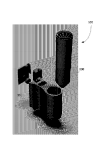
[0082] Reference is first made to FIG. lA which is a partial exploded view of
an example air
sampling system 100, in accordance with embodiments of the present disclosure.
The air sampling
system 100 may be used for continuously monitoring air in an indoor
environment. FIG. lA
illustrates a collection chamber 200 and an optical detection unit/subsystem
201. The collection
chamber 200 is removably coupled to the optical detection unit 201. As will be
explained in greater
detail below, the collection chamber 200 collects liquid water that is
condensed from air sampled
from the indoor environment. The collection chamber 200 also includes a
reaction compartment
in which a target analyte may react with a bioreceptor. The optical detection
unit 201 houses optical
components that enable the detection of a target analyte inside the collection
chamber 200. The
collection chamber 200 is replaceable ¨ that is, the collection chamber 200
may be replaced by
another collection chamber containing a different bioreceptor, and the optical
detection unit 201
may operate in a similar manner to enable detection of a different target
analyte. The air sampling
system 100 may be portable or fixed in place in an indoor environment. For
example, the air
sampling system 100 may be mounted on a wall of a room inside a facility and
used to monitor
the air of the room.
[0083] Reference is now made to FIG. 1B which is a high-level schematic
diagram of the air
sampling system 100. The air sampling system 100 includes a controller (not
shown in FIG. 1B).
The controller is configured to control the overall operation of the air
sampling system 100. In at
least some embodiments, the controller includes one or more processors, such
as microprocessors.
11
Date Recue/Date Received 2020-11-27
Rowand Ref: 347-0003CAP1
Specification
The processor is communicably coupled with various devices and subsystems,
some of which are
illustrated in FIG. 1B.
[0084] The air sampling system 100 includes a fan 102, or similar device for
creating a flow of air
from the sampling environment into the air sampling system 100. The fan 102
helps to circulate
air in the sampling environment in order to draw air from different parts of
the sampling
environment. The fan 102 may be controlled to draw air into the air sampling
system 100 on a
continuous basis, or at specific times or time intervals. For example, air may
be drawn into the air
sampling system 100 at defined intervals. As will be explained further below,
in some
embodiments, the fan 102 may be operated to draw in more air from the sampling
environment as
needed to increase the liquid level (i.e. more condensation) in the collection
chamber 200.
[0085] The air sampling system 100 also includes a cooling unit 110. The
cooling unit 110
provides localized cooling of air. In particular, the cooling unit 110 is
configured to cool the air
that is drawn into the air sampling system 100 to cause condensation of water
vapor in the air. The
temperature of the cooling unit 110 may be varied by a controller of the air
sampling system 100.
[0086] The collection chamber 200 of the air sampling system 100 is arranged
such that it is
located substantially vertically below the cooling unit 110. Incoming air in
the air sampling system
100 is cooled by the cooling unit 110 to cause condensation of the water vapor
in the air. As the
air is cooled, airborne particles, or aerosols, combine with condensate
droplets to form larger
particles that, due to the effect of gravity, drop into and collect in the
collection chamber 200.
[0087] The air sampling system 100 also includes air particulate monitors 104a
and 104b. The air
particulate monitors 104a and 104b are used for measuring the particulate
matter content (e.g. solid
particles such as dust, powder, pellets, etc.) in the ambient air. The air
particulate monitors 104a
and 104b may be associated with an air inlet and an air outlet, respectively,
of the air sampling
system 100 such that air being drawn into, as well as air being expelled out
of, the air sampling
system 100 may be monitored.
[0088] The air sampling system may include temperature and humidity sensors
106a and 106b at
an air inlet and an air outlet, respectively. In at least some embodiments,
the temperature and
humidity sensors 106a and 106b may be used for obtaining measurements that is
used for
controlling the cooling unit 110. For example, the temperature and/or humidity
of incoming air
12
Date Recue/Date Received 2020-11-27
Rowand Ref: 347-0003CAP1
Specification
may be measured, and the controller may vary a temperature of the cooling unit
110 based on the
measurements obtained from the temperature and/or humidity sensors.
[0089] The air sampling system may also include one or more air pumps 120 for
drawing air out
of the air sampling system 100. The air may be expelled through an exhaust and
back into the
sampling environment. The air pump 120 may, for example, be a high-volume
sampling pump.
The air sampling system may also include a hygroscopic filter 118, which
removes moisture and
particles from the air.
[0090] The air sampling system 100 may also include a communication subsystem
(not shown in
FIG. 1B) which allows the air sampling system 100 to communicate over a
wireless network. The
communication subsystem may include, at least, a receiver, a transmitter, and
associated
components, such as one or more antenna elements, local oscillators (L0s), and
a processing
module such as a digital signal processor (DSP). The antenna elements may be
embedded or
internal to the air sampling system 100 and a single antenna may be shared by
both receiver and
transmitter. The particular design of the wireless communication subsystem may
depend on the
wireless network in which the air sampling system 100 is intended to operate.
[0091] The air sampling system 100 may also include a notification
module/unit. The notification
unit may generate signals representing notifications indicating detection of
one or more target
analytes in the air sampling system 100. More particularly, if a target
analyte is detected in liquid
that is collected in the collection chamber 200, the notification unit of the
air sampling system 100
may generate notifications of the detection. For example, a notification, such
as a visual or auditory
alert or message, may be displayed on a display device associated with the air
sampling system
100, or transmitted wirelessly to one or more computing devices via a wireless
network (e.g. over
Wi-Fi, Bluetooth, etc.). The notification unit may also generate notifications
relating to operation
of the air sampling system 100. For example, a controller associated with the
air sampling system
100 may determine that the collection chamber 200 should be replaced, for
example, after a
pathogen is detected by the air sampling system 100 or if the particulate
matter content of the
sampled air or collected liquid in the air sampling system 100 is determined
to fall outside an
acceptable level/range. The controller may then cause the notification unit to
generate and provide
notifications to an operator of the air sampling system 100 to replace the
collection chamber 200.
13
Date Recue/Date Received 2020-11-27
Rowand Ref: 347-0003CAP1
Specification
[0092] Reference is now made to FIG. 2 which is a partial side cross-sectional
view of internal
components of the air sampling system 100. FIG. 2 illustrates an example
arrangement of internal
components; it will be understood that different arrangements and additional
internal components
may be possible. The air sampling system 100 includes an air intake unit 210
that is fluidly
connected to the collection chamber 200. The air intake unit 210 facilitates
flow of air from the
ambient environment into the air sampling system 100. As shown in FIG. 2, the
air intake unit 210
defines an inlet 212 and an air inflow channel 213. The inlet 212 is located
at a top end of the air
inflow channel 213. The air inflow channel 213 defines an airflow passageway
(or path) into the
air sampling system 100. Ambient air enters the air inflow channel 213 via the
inlet 212. For
example, the fan 102 may be configured to cause ambient air to flow into the
air inflow channel
213. In at least some embodiments, the air inflow channel 213 is substantially
vertically oriented.
That is, inflowing air moves substantially in a downward direction within the
air inflow channel
213.
[0093] The air intake unit 210 may, in some embodiments, include a tubular
member or vessel
that defines the air inflow channel 213. As shown in FIG. 2, the air intake
unit 210 may include a
housing 211 and the air inflow channel 213 may be a tubular member that
extends through the
housing 211. The tubular member may be elongate and extend from the air intake
unit 210 at least
partially into the collection chamber 200. In particular, the air inflow
channel 213 is fluidly
connected with the collection chamber 200, such that fluids (e.g. air,
condensed liquid water)
flowing through the air inflow channel 213 enter the collection chamber 200
due to gravity.
[0094] In at least some embodiments, the collection chamber 200 is removably
coupled to the air
intake unit 210. That is, the collection chamber 200 can be operatively
coupled with the air
sampling system 100 and can also be removed from the air sampling system 100
(e.g. by detaching).
For example, the collection chamber 200 may be coupled to the air intake unit
210 using a threaded
connection. In FIG. 2, a coupler component 208 is used to connect a housing
211 of the air intake
unit 210 with the collection chamber 200. The coupler component 208 may be
affixed to the
housing 211 and the collection chamber 200 may be removably connected to the
coupler
component 208. The coupler component 208 may itself be a separate component
that is
independent of and compatible with the air sampling system 100. In some other
embodiments, the
collection chamber 200 may be directly coupled to the housing 211 (i.e.
without an intermediary
14
Date Recue/Date Received 2020-11-27
Rowand Ref: 347-0003CAP1
Specification
coupler component). Various different coupling mechanisms may be used for
operatively
connecting the collection chamber 200 to the air sampling system 100. the
collection chamber 200
can be removed from the air sampling system 100 and replaced by another
collection chamber.
For example, a collection chamber containing a different analyte of interest
may be operatively
coupled to the air sampling system 100. In this way, the air sampling system
100 can be used for
various different purposes (e.g. detection of a different analyte in the
ambient air, etc.), or for the
same purpose for a prolonged period of time (e.g. by replacing the collection
chamber with a new
one).
[0095] The air sampling system 100 also includes an air outflow channel 214.
Ambient air that
enters the air sampling system 100 via the air inflow channel 213 passes
through the collection
chamber 200 and is subsequently expelled from the air sampling system 100 via
the air outflow
channel 214. In particular, the air outflow channel 214 is fluidly connected
to the collection
chamber 200. As shown in FIG. 2, in some embodiments, the air outflow channel
214 may be
oriented substantially vertically.
[0096] The air sampling system 100 includes a cooling unit 110. In the example
embodiment of
FIG. 2, the cooling unit 110 comprises one or more cold plates that are
disposed downstream of
the inlet 212. The cold plates may, for example, be made of aluminum. The
cooling unit 110 is
mounted to the housing 211 of the air intake unit 210. In at least some
embodiments, the cooling
unit (e.g. cold plates) may be supported in thermal contact with at least a
portion of the air inflow
channel. In FIG. 2, the cooling unit 110 extends vertically along the housing
211, covering a
defined length of the air inflow channel 213. The cooling unit 110 is
configured to cool air passing
through at least a portion (e.g. a covered length) of the air inflow channel
213. In particular, the
cooling unit 110 may be controlled (for example, by a controller of the air
sampling system 100)
to cause condensation of the water vapor in the air passing through at least a
portion of the air
inflow channel 213. The controller varies the temperature of the cooling unit
110. In at least some
embodiments, the temperature of the cooling unit 110 may be varied in order to
maintain a desired
volume of liquid water in the collection chamber 200. As air passes in the air
inflow channel 213,
the cooling unit 110 causes water droplets to form due to condensation. By
varying the temperature
of the cooling unit 110, the volume of liquid collecting in the collection
chamber 200 can be
Date Recue/Date Received 2020-11-27
Rowand Ref: 347-0003CAP1
Specification
controlled. For example, a minimum level of liquid may be maintained in the
collection chamber
200 by monitoring and controlling the temperature of the cooling unit 110.
[0097] In some embodiments, the cooling unit 110 may be configured to cool air
passing through
the air outflow channel 214. More specifically, the air that is removed from
the collection chamber
200 via the air outflow channel 214 may be cooled by the cooling unit 110. For
example, the
warmer, drier air inside the collection chamber 200 may absorb some of the
liquid water in the
collection chamber 200 and reduce the volume of collected liquid. To prevent a
variance in liquid
level, the air flowing out from the collection chamber 200 may be cooled to
remove (i.e. via
condensation) liquid that has been absorbed.
[0098] In at least some embodiments, the air sampling system 100 includes a
sensing unit for
determining a volume of liquid in the collection chamber 200, and the cooling
unit 110 may be
controlled in response to signals generated by the sensing unit. For example,
the sensing unit may
be a level sensor associated with the collection chamber 200. The level sensor
may, for example,
be a capacitive sensor. Based on signals generated by the level sensor, the
controller of the air
sampling system 100 may determine whether a liquid level in the collection
chamber 200 deviates
from a defined threshold level. For example, the controller may detect if the
liquid level is above
or below a defined threshold (or a range of volume defined by lower and upper
limit values). If
the liquid level falls below the threshold, the temperature of the cooling
unit 110 may be varied to
allow more liquid to condense from the inflowing air. For example, the
controller may lower the
temperature of the cooling unit 110 to increase the rate of condensation in
the air inflow channel
213. Additionally, or alternatively, the fan 102 of the air sampling system
100 may be caused to
increase air flow into the air inflow channel 213.
[0099] The air sampling system 100 may include other sensors, such as a
temperature sensor, a
humidity sensor, a liquid flow sensor etc. which may be used for maintaining a
desired volume of
liquid (i.e. a defined level or range of volume) in the collection chamber
200. In particular, the
cooling unit 110 may be controlled based on measurements obtained from one or
more of these
sensors. By continuously monitoring the temperature, humidity, flow rates,
etc., the air sampling
system 100 is configured to maintain a substantially constant level of liquid
corresponding to a
desired solution volume for detection of a target analyte.
16
Date Recue/Date Received 2020-11-27
Rowand Ref: 347-0003CAP1
Specification
[0100] The air sampling system 100 includes a liquid inflow channel 204 having
a liquid inflow
port. The liquid inflow channel 204 is fluidly connected to the collection
chamber 200. The air
sampling system 100 also includes a liquid outflow channel. In some
embodiments, the liquid
inflow channel 204 and the liquid outflow channel may be the same structural
component. That is,
liquid may flow into and out of the collection chamber 200 via the same flow
channel. For example,
a liquid pump may cause liquid to flow into and out of the collection chamber
200. As will be
described in greater detail below, various liquid solutions may be introduced
into the collection
chamber 200 via the liquid inflow channel 204. The solutions may subsequently
be removed using
the same flow channel or a separate liquid outflow channel. In at least some
embodiments, the
liquid inflow channel 204 and the liquid outflow channel may be fluidly
connected to the reaction
compartment. For example, an outlet opening of the liquid inflow channel 204
(and inlet opening
of the liquid outflow channel) may be located adjacent to or inside the
reaction compartment, such
that liquid flowing in the liquid inflow channel 204 enters the reaction
compartment directly (and
similarly, liquid in the reaction compartment is removed via the liquid
outflow channel).
[0101] In some embodiments, the air sampling system 100 may include a flow
sensor associated
with at least one of the liquid inflow channel 204 or the liquid outflow
channel. The flow sensor
is configured to measure the rate of flow of liquid into and/or out of the
collection chamber 200.
The cooling unit 110 may, in some embodiments, be controlled based on
measurements obtained
from the flow sensor(s). In particular, the controller of the air sampling
system 100 may determine,
based on measurements of the flow sensor(s), whether to vary the temperature
of the cooling unit
110 in order to adjust the volume of liquid in the chamber 200.
[0102] The collection chamber 200 of the air sampling system 100 will be
described in greater
detail with reference to FIGS. 3, 4A-4B, 5A-5B and 6A-6C. In at least some
embodiments, the
collection chamber 200 includes a flow column. A perspective view of an
example flow column
300 is shown in FIG. 3. As shown in FIGS. 6A-6B, the flow column 300 may be
centrally disposed
inside the collection chamber 200. The flow column 300 is fluidly connected to
the air inflow
channel 213. In particular, fluid (e.g. air, condensed liquid water) flowing
through the air inflow
channel 213 may enter an opening 301 defined at a top end of the flow column
300. The flow
column 300 also defines a plurality of slots 302 which allow flow of fluid
therethrough and into
the collection chamber 200. For example, the plurality of slots 302 may allow
drainage of
17
Date Recue/Date Received 2020-11-27
Rowand Ref: 347-0003CAP1
Specification
condensed liquid water flowing from the air inflow channel 213. In the example
embodiment of
FIG. 3, the flow column 300 includes a conical top member defining a lip (or
flange) 304 and a
plurality of slots 302. Other configurations may be possible for providing
fluid connection between
the air inflow channel 213 and the flow column 300.
[0103] Reference is made to FIGS. 4A and 4B which show side views of the
example flow column
300 of FIG. 3. The flow column 300 defines a plurality of apertures 350 along
a cylindrical portion
of the flow column 300 and a central bore extending through the cylindrical
portion. The plurality
of apertures 350 allow for fluid movement between the flow column 300 and the
collection
chamber 200. In particular, liquid water and air can flow through the flow
column 300 (for example,
in the bore extending through the cylindrical portion) and enter the
collection chamber 200 via the
apertures 350. As the flow column 300 is disposed inside the collection
chamber 200, the fluid in
the collection chamber 200 may flow into and out of the flow column 300
through the apertures
350.
[0104] The collection chamber 200 allows for detection of one or more analytes
in the liquid
solution that collects in the collection chamber 200. For a given analyte of
interest, the collection
chamber 200 includes at least one substrate containing a reagent/receptor that
is known to react
with the analyte. More particularly, the collection chamber 200 includes an
active target substrate
having a surface that is at least partly coated with bioreceptors. In at least
some embodiments, the
bioreceptors may be antibodies which may interact and bind with antigens of a
given pathogen.
For example, the bioreceptors may be antibodies for a given target virus. The
active target substrate
may, in some embodiments, be a piece of resin that is treated with a
receptor/reagent. The receptor
serves as a selective "glue" that allows an analyte of interest to bind to the
receptor (and the active
target substrate) while other particles will not.
[0105] The active target substrate may be located at a bottom portion of the
collection chamber
200. In particular, the active target substrate may be included in (or coupled
to) the flow column
300 inside the collection chamber 200. For example, the active target
substrate may be inserted
into a slot 360 that is defined at a bottom portion of the flow column 300.
The active target substrate
may, for example, be positioned below the plurality of apertures 350 defined
on the flow column
300.
18
Date Recue/Date Received 2020-11-27
Rowand Ref: 347-0003CAP1
Specification
[0106] In some embodiments, the collection chamber 200 may additionally
include a reference
target substrate. The reference target substrate is not coated with any
receptor/reagent. The
reference target substrate may, for example, be a piece of resin. As will be
explained further below,
a reference target substrate may allow the air sampling system 100 to account
for the presence of
contaminants in the sampled ambient air. In particular, the reference target
substrate allows for
cancelling out the optical effects (during an analyte detection phase) that
are caused by
contaminants different from the analyte of interest.
[0107] Reference is made to FIGS. 6A and 6B which show side cross-sectional
views of a
collection chamber 200 of the air sampling system 100. In at least some
embodiments, the air
sampling system 100 includes a plurality of glass beads 390 that are disposed
inside the collection
chamber 200. The surfaces of the plurality of glass beads are exposed to
liquid that collects in the
collection chamber 200. During an analyte detection phase, the inflowing air
from the ambient
environment is caused to "bubble" through the liquid collected in the
collection chamber 200. This
"bubbling" refers to the forced movement of air, in which one or more
contaminants may be
dissolved or suspended, through a liquid solution. The forced movement may be
effected, for
example, through the use of an air pump or other air transferring device. By
bubbling the inflowing
air through the liquid in the collection chamber 200, particles of an analyte
of interest may be
scrubbed out into the liquid solution. The glass beads 390 in the collection
chamber 200 may be
useful for preventing re-aerosolization of such particles that are removed
through the bubbling
process. For example, re-aerosolization of virus particles into air outflowing
from the collection
chamber 200 is harmful and frustrates the virus detection process of the air
sampling system 100.
By increasing the reaction surface area between the glass beads 390 and the
liquid media, re-
aerosolization of the removed particles may be prevented or reduced.
[0108] FIGS. 6A and 6B show that the glass beads 390 may be positioned between
the flow
column 300 and the inner wall of the collection chamber 200. More
specifically, the flow column
300 and the collection chamber 200 may define an annular space 365, and the
glass beads 390 may
fit in the annular space 365. The fluid flowing from the air intake unit 210
and/or the air inflow
channel 213 into the collection chamber 200 may move in the annular space 365
through gaps
between the glass beads 390. In particular, fluid may flow through the
apertures 350 defined on
the flow column 300 and between the glass beads 390. The glass beads 390 may
have different
19
Date Recue/Date Received 2020-11-27
Rowand Ref: 347-0003CAP1
Specification
sizes, or they may all have a uniform size. In at least some embodiments, the
size of the apertures
350 may be smaller than the cross-sectional area of the glass beads 390, which
prevents the glass
beads 390 from entering the interior of the flow column 300 through the
apertures 350. That is,
the apertures 350 may be sized so as to ensure that the glass beads 390 are
disposed in the space
between (outer wall of) the flow column 300 and the inner wall of the
collection chamber 200. For
example, the glass beads 390 may be disposed against the exterior side of the
flow column 300,
without covering the apertures 350. The glass beads 390 may, for example, be
supported at a
defined distance away from the apertures 350, or may be shaped so as not to
fittingly engage the
apertures 350.
[0109] The air sampling system 100 may also include a permeable stopper 310
that supports the
plurality of glass beads 390 above and in spaced relation to a bottom wall of
the collection chamber
200. More specifically, the stopper 310 maintains the glass beads 390 a
predetermined distance
away from the bottom of the collection chamber 200. The stopper 310 and the
bottom wall of
collection chamber 200 define a space ¨ a reaction compartment ¨ in which the
active target
substrate is disposed. The reaction compartment is a space located at a bottom
portion of the
collection chamber 200 where an analyte of interest is allowed to interact
with a receptor/reagent.
The stopper 310 ensures that the glass beads 390 are maintained above and out
of the reaction
compartment. FIG. 6C shows a magnified view of a reaction compartment inside
the collection
chamber 200. The stopper 310 is permeable, such that fluid flowing in an upper
portion of the
collection chamber 200, including ambient air, condensed liquid water, and
liquid solution in the
collection chamber 200, reaches the reaction compartment. The stopper 310 may,
for example,
define a plurality of openings through which fluid can flow into the reaction
compartment. The
openings may be sized so as to prevent any of the glass beads 390 from
entering the reaction
compartment. In particular, the fluid movement allows for the analyte in the
liquid solution to react
with the receptor/reagent on the active target substrate.
[0110] FIG. 5A shows an example target holder 330 which may be located in the
reaction
compartment of the collection chamber 200. The target holder 330 supports at
least an active target
substrate 370. In particular, the target holder 330 supports the active target
substrate 370 in fluid
contact with the liquid in the collection chamber 200. The condensed liquid
water is allowed to
flow into the reaction compartment and the target holder 330 exposes the
active target substrate
Date Recue/Date Received 2020-11-27
Rowand Ref: 347-0003CAP1
Specification
370 to the liquid water. In the example of FIG. 5A, the target holder 330
additionally supports a
reference target substrate 380, and includes a divider 320 for isolating the
optical effects of one of
the active target substrate 370 and the reference target substrate 380 from
the other.
[0111] As illustrated in FIG. 1A, the air sampling system 100 includes an
optical detection unit
201 that is removably coupled to the collection chamber 200. The optical
detection unit 201 houses
various optical components that allow for detection of particles in the liquid
solution collected in
the collection chamber 200. In particular, the optical detection unit 201 is
configured to
independently illuminate the active target substrate 370 and the reference
target substrate 380 using
a light source. The light source may, for example, be an infrared laser. The
optical detection unit
201 may include one or more bandpass filters, such as a laser light bandpass
filter. The optical
detection unit 201 includes a detector, such as an infrared detector, and a
focusing lens that filters
light from the light source onto the detector. The light source may be pulse
modulated at a
frequency that is dependent on the receptors and/or analyte of interest.
[0112] Reference is now made to FIG. 7 which shows, in flowchart form, an
example method 700
for detecting airborne pathogens. The method 700 may be performed by an air
quality monitoring
system, such as the air sampling system 100 of FIG. 1. More particularly, the
operations of method
700 may be performed by a controller (which may include one or more
processors) of the air
sampling system 100.
[0113] In operation 702, air from an ambient environment is sampled. The
ambient air is collected
by the air sampling system by, for example, operating a fan to cause air to
flow into an air intake
unit (i.e. air inflow channel) associated with the air sampling system. The
inflowing air passes
through a cooling unit, which causes condensation of the water vapor in the
air to liquid form. The
controller can vary the temperature of the cooling unit to cause a desired
volume of liquid to be
condensed from the inflowing air. The collection chamber initially contains
only a saline solution,
and the particulate matter (e.g. dirt, virus, etc.) in the sampled air is
added to the liquid solution in
the collection chamber.
[0114] In at least some embodiments, the inflowing air may be bubbled through
the saline solution
in the collection chamber, in order to trap the analyte of interest in the
liquid (or "analyte solution")
and to allow the analyte in the liquid to react with the active target
substrate in the reaction
21
Date Recue/Date Received 2020-11-27
Rowand Ref: 347-0003CAP1
Specification
compartment of the collection chamber. The inflowing air may be bubbled for a
predetermined
period of time. The analyte solution is subsequently pumped out of the
collection chamber, in
operation 704, and a wash of cleaning solution (e.g. distilled water) is
flushed through the
collection chamber. A liquid inflow/outflow channel may be used for removing
the analyte
solution from and introducing the cleaning solution into the collection
chamber. In particular, the
analyte solution is drawn out from the reaction compartment of the collection
chamber. The
volume of cleaning solution used may be just enough to cover the targets (i.e.
active target substrate
and optionally, reference target substrate) that are located in the reaction
compartment.
[0115] In operation 706, a liquid solution containing a receptor/reagent (or
"reagent solution") that
is known to react with the analyte of interest is introduced into the
collection chamber. The
receptor/reagent may, for example, be antibodies for a virus that is being
monitored by the air
sampling system. The specific receptor/reagent used in the reagent solution
depends on the analyte
being detected. The volume of reagent solution used may be just enough to
cover the targets. In
particular, the volume of reagent solution may be less than the volume of
liquid solution used
during the air sampling phase ¨ the receptor/reagent only needs to cover the
active (and optionally,
reference) target substrates.
[0116] The reagent solution is removed from the collection chamber, in
operation 708, and an
optical detection operation 710 follows. During optical detection, a light
source, such as an infrared
laser, is directed at the active target (and reference target) substrate. The
light directed at the target
is modulated at a particular frequency, which depends on the specific analyte
of interest and
receptor used in the detection. The light serves as an excitation source for
the analyte/receptor,
causing proteins on the surface of the analyte/receptor to vibrate. The
spectrum of light that
bounces off the analyte/receptor can be detected and analyzed to identify the
specific analyte of
interest. For example, for a given analyte/receptor combination, an optical
detection unit of the air
sampling system may monitor for light that has a specific frequency. In some
embodiments, a
bandpass filter may be used in conjunction with the light source, and a
focusing lens may filter the
reflected light onto a detector. If reflected light of a specific frequency is
detected, the analyte of
interest may be determined to be present on the active target substrate. Upon
detection of the
analyte, the controller may cause notifications to be generated based on the
results of the detection,
in operation 712.
22
Date Recue/Date Received 2020-11-27
Rowand Ref: 347-0003CAP1
Specification
[0117] In at least some embodiments, the light source of the optical detection
unit may also direct
light at the reference target substrate. Since the sampled air may have
contaminants (e.g. dust
particles) which can affect analyte detection, the reference target substrate
is used to cancel any
optical effects resulting from the contaminants. More particularly, a
reference target check
operation may be performed. This is done by comparing the reference signal
from a current
measurement of reflected energy by the reference target with the reference
signal from an initial
measurement of the reflected energy (i.e. measurement of the energy reflected
at reference target
in the initial setup of the system), to monitor for degradation in measured
energy level.
[0118] The various embodiments presented above are merely examples and are in
no way meant
to limit the scope of this application. Variations of the innovations
described herein will be
apparent to persons of ordinary skill in the art, such variations being within
the intended scope of
the present application. In particular, features from one or more of the above-
described example
embodiments may be selected to create alternative example embodiments
including a sub-
combination of features which may not be explicitly described above. In
addition, features from
one or more of the above-described example embodiments may be selected and
combined to create
alternative example embodiments including a combination of features which may
not be explicitly
described above. Features suitable for such combinations and sub-combinations
would be readily
apparent to persons skilled in the art upon review of the present application
as a whole. The subject
matter described herein and in the recited claims intends to cover and embrace
all suitable changes
in technology.
23
Date Recue/Date Received 2020-11-27