Note: Descriptions are shown in the official language in which they were submitted.
CA 03101308 2020-11-23
WO 2019/244149 PCT/IL2019/050677
EMERGENCY KIT
RELATED APPLICATION/S
This application claims the benefit of priority of Israeli Patent Application
No.
260161 filed 19 June, 2018, the contents of which are incorporated herein by
reference in their entirety.
TECHNICAL FIELD
The invention in some embodiments thereof relates to the field of emergency
medical service and other emergency services.
BACKGROUND
In case of emergency, when every second matters, there is sometimes a great
difficulty
to locate the exact address: building number, or specific entrance.
As a result, a lot of time is wasted in locating the right building.
Sometimes, a
parking gate or entrance of main door are locked, therefore emergency teams
often lose the
"golden minutes" (critic minutes for life saving).
There is a long felt need to provide a solution to the above-mentioned and
other problems of the prior art.
SUMMARY
According to an aspect of some embodiments of the invention, there is
provided an emergency kit (10A), including a first apparatus (38A) including:
a long-
range communication device including a unique identity module (30A), for
receiving
(24) a status of the first apparatus (38A) from another long-range
communication
device (26B); and a first member (16A), including at least one member selected
from
a group consisting of a visual, vocal and transmitting device, for being
turned on once
the status is active, thereby the first apparatus (38A) indicates a first
location of an
emergency event setting the status to active.
According to some embodiments of the invention, the emergency kit (10A)
further includes a second apparatus (34A), including: a first short-range
transceiver
(32B1), for receiving the status from the first apparatus (38A); and a second
member
(16B1), including at least one member selected from a group consisting of a
visual,
vocal and transmitting device, for being turned on once the status is active,
thereby the
second apparatus (34A) indicates a second location of the emergency event,
being
improved in relation to the first location.
1
CA 03101308 2020-11-23
WO 2019/244149
PCT/IL2019/050677
According to some embodiments of the invention, the emergency kit (10A)
further includes at least a third apparatus (34B), including: a second short-
range
transceiver (32B2), for receiving the status from any of the apparatuses (38A,
34A);
and a third member (16B2), including at least one member selected from a group
consisting of a visual, vocal and transmitting device, for being turned on
once the
status is active, thereby the at least third apparatus (34B) indicates at
least a third
location of the emergency event, being improved in relation to any of the
locations.
According to some embodiments of the invention, the first apparatus (38A)
further includes: a third short-range transceiver (32A), for receiving the
status from
the unique identity module (30A), for transmitting the status to other
apparatuses
(34A).
According to some embodiments of the invention, the transmitting device is
configured to open (18) a gate.
According to an aspect of some embodiments of the invention, there is
provided an emergency notification system including: a network communication
device including a caller application configured for opening when a call is
made on
the network communication device to an emergency number, automatically
activating
at least one emergency notification devices facilitating access of an
emergency
responder to a location of an emergency event.
According to some embodiments of the invention, the caller application is
configured to configured for activating the at least one emergency
notification devices
facilitating access of an emergency responder to a location of the network
communication device.
According to some embodiments of the invention, the caller application is
further configured for displaying on the caller network communication device a
menu
of control options for a plurality of the emergency notification devices.
According to some embodiments of the invention, the system further includes:
a responder communication device configured to open a responder application
coordinated to the caller application for displaying on the responder
communication
device an indicator of a status of the plurality of the emergency notification
devices.
According to some embodiments of the invention, the responder application is
further configured for displaying on the responder communication device a menu
of
control options for a plurality of the emergency notification devices.
According to some embodiments of the invention, the caller application is
further configured for presenting a menu for verifying a location of an
emergency
event.
According to some embodiments of the invention, the system further includes:
a responder communication device configured to open a responder application
coordinated to the caller application for displaying on the responder
communication
device an indicator of a status of the verification.
2
CA 03101308 2020-11-23
WO 2019/244149
PCT/IL2019/050677
According to some embodiments of the invention, the caller application is
further configured for presenting a menu for verifying a location of an
emergency
event.
According to some embodiments of the invention, the system further includes:
a responder communication device configured to open a responder application
coordinated to the caller application for displaying on the responder
communication
device an indicator of a status of the verification.
According to an aspect of some embodiments of the invention, there is
provided a method of coordinating emergency information including: calling an
emergency number on a network communication device; opening a caller
application
on the network communication; controlling an emergency notification apparatus
via
the caller application.
According to some embodiments of the invention, the method further includes:
the emergency notification apparatus performing at least one of indicating an
entrance
to a building and opening a gate.
According to some embodiments of the invention, the controlling is over a
public network.
According to some embodiments of the invention, the controlling includes
sending a command from the caller application over a public network to the
emergency notification apparatus.
According to some embodiments of the invention, the method further includes:
opening a responder application on a network communication device of an
emergency
responder; coordinating the responder application with the caller application
over a
network; and indicating a status of the emergency notification apparatus on
the
responder device.
According to some embodiments of the invention, the method further includes:
controlling an emergency notification apparatus via the responder application.
According to some embodiments of the invention, the method further includes
the caller application presenting a menu for verifying a location of an
emergency
event and the responder application coordinated to the caller application for
displaying
on the responder communication device an indicator of a status of the
verification.
According to some embodiments of the invention, the method further includes
the caller application sending a sensor output from the network communication
device
to the responder device and the responder application displaying the sensor
output to
the responder.
According to an aspect of some embodiments of the invention, there is
provided an emergency kit, including:
¨ a long-range communication device including a unique identity module; and
¨ a visual/vocal/transmitting device, for being turned on once the status
is active,
3
CA 03101308 2020-11-23
WO 2019/244149
PCT/IL2019/050677
thereby the apparatus indicates a first location of an emergency event setting
the
active status.
Unless otherwise defined, all technical and/or scientific terms used herein
have
the same meaning as commonly understood by one of ordinary skill in the art to
which
the invention pertains. Although methods and materials similar or equivalent
to those
described herein can be used in the practice or testing of embodiments of the
invention, exemplary methods and/or materials are described below. In case of
conflict, the patent specification, including definitions, will control. In
addition, the
materials, methods, and examples are illustrative only and are not intended to
be
necessarily limiting.
As will be appreciated by one skilled in the art, some embodiments of the
present invention may be embodied as a system, method or computer program
product. Accordingly, some embodiments of the present invention may take the
form
of an entirely hardware embodiment, an entirely software embodiment (including
firmware, resident software, micro-code, etc.) or an embodiment combining
software
and hardware aspects that may all generally be referred to herein as a
"circuit,"
"module" or "system." Furthermore, some embodiments of the present invention
may
take the form of a computer program product embodied in one or more computer
readable medium(s) having computer readable program code embodied thereon.
Implementation of the method and/or system of some embodiments of the
invention
can involve performing and/or completing selected tasks manually,
automatically, or a
combination thereof. Moreover, according to actual instrumentation and
equipment of
some embodiments of the method and/or system of the invention, several
selected
tasks could be implemented by hardware, by software or by firmware and/or by a
combination thereof, e.g., using an operating system.
For example, hardware for performing selected tasks according to some
embodiments of the invention could be implemented as a chip or a circuit. As
software, selected tasks according to some embodiments of the invention could
be
implemented as a plurality of software instructions being executed by a
computer
using any suitable operating system. In an exemplary embodiment of the
invention,
one or more tasks according to some exemplary embodiments of method and/or
system as described herein are performed by a data processor, such as a
computing
platform for executing a plurality of instructions. Optionally, the data
processor
includes a volatile memory for storing instructions and/or data and/or a non-
volatile
storage, for example, a magnetic hard-disk and/or removable media, for storing
instructions and/or data. Optionally, a network connection is provided as
well. A
display and/or a user input device such as a keyboard or mouse are optionally
provided as well.
4
CA 03101308 2020-11-23
WO 2019/244149
PCT/IL2019/050677
Any combination of one or more computer readable medium(s) may be
utilized for some embodiments of the invention. The computer readable medium
may
be a computer readable signal medium or a computer readable storage medium. A
computer readable storage medium may be, for example, but not limited to, an
electronic, magnetic, optical, electromagnetic, infrared, or semiconductor
system,
apparatus, or device, or any suitable combination of the foregoing. More
specific
examples (a non-exhaustive list) of the computer readable storage medium would
include the following: an electrical connection having one or more wires, a
portable
computer diskette, a hard disk, a random access memory (RAM), a read-only
memory
(ROM), an erasable programmable read-only memory (EPROM or Flash memory), an
optical fiber, a portable compact disc read-only memory (CD-ROM), an optical
storage device, a magnetic storage device, or any suitable combination of the
foregoing. In the context of this document, a computer readable storage medium
may
be any tangible medium that can contain, or store a program for use by or in
connection with an instruction execution system, apparatus, or device.
A computer readable signal medium may include a propagated data signal with
computer readable program code embodied therein, for example, in baseband or
as
part of a carrier wave. Such a propagated signal may take any of a variety of
forms,
including, but not limited to, electro-magnetic, optical, or any suitable
combination
thereof. A computer readable signal medium may be any computer readable medium
that is not a computer readable storage medium and that can communicate,
propagate,
or transport a program for use by or in connection with an instruction
execution
system, apparatus, or device.
Program code embodied on a computer readable medium and/or data used
thereby may be transmitted using any appropriate medium, including but not
limited
to wireless, wireline, optical fiber cable, RF, etc., or any suitable
combination of the
foregoing.
Computer program code for carrying out operations for some embodiments of
the present invention may be written in any combination of one or more
programming
languages, including an object oriented programming language such as Java,
Smalltalk, C++ or the like and conventional procedural programming languages,
such
as the "C" programming language or similar programming languages. The program
code may execute entirely on the user's computer, partly on the user's
computer, as a
stand-alone software package, partly on the user's computer and partly on a
remote
computer or entirely on the remote computer or server. In the latter scenario,
the
remote computer may be connected to the user's computer through any type of
network, including a local area network (LAN) or a wide area network (WAN), or
the
connection may be made to an external computer (for example, through the
Internet
using an Internet Service Provider).
5
CA 03101308 2020-11-23
WO 2019/244149 PCT/IL2019/050677
Some embodiments of the present invention may be described below with
reference to flowchart illustrations and/or block diagrams of methods,
apparatus
(systems) and computer program products according to embodiments of the
invention.
It will be understood that each block of the flowchart illustrations and/or
block
diagrams, and combinations of blocks in the flowchart illustrations and/or
block
diagrams, can be implemented by computer program instructions. These computer
program instructions may be provided to a processor of a general purpose
computer,
special purpose computer, or other programmable data processing apparatus to
produce a machine, such that the instructions, which execute via the processor
of the
computer or other programmable data processing apparatus, create means for
implementing the functions/acts specified in the flowchart and/or block
diagram block
or blocks.
These computer program instructions may also be stored in a computer
readable medium that can direct a computer, other programmable data processing
apparatus, or other devices to function in a particular manner, such that the
instructions stored in the computer readable medium produce an article of
manufacture including instructions which implement the function/act specified
in the
flowchart and/or block diagram block or blocks.
The computer program instructions may also be loaded onto a computer, other
programmable data processing apparatus, or other devices to cause a series of
operational steps to be performed on the computer, other programmable
apparatus or
other devices to produce a computer implemented process such that the
instructions
which execute on the computer or other programmable apparatus provide
processes
for implementing the functions/acts specified in the flowchart and/or block
diagram
block or blocks.
Some of the methods described herein are generally designed only for use by a
computer, and may not be feasible or practical for performing purely manually,
by a human
expert. A human expert who wanted to manually perform similar tasks might be
expected to
use completely different methods, e.g., making use of expert knowledge and/or
the pattern
recognition capabilities of the human brain, which would be vastly more
efficient than
manually going through the steps of the methods described herein.
Data and/or program code may be accessed and/or shared over a network, for
example the Internet. For example, data may be shared and/or accessed using a
social
network. A processor may include remote processing capabilities for example
available over a network (e.g. the Internet). For example, resources may be
accessed
via cloud computing. The term "cloud computing" refers to the use of
computational
resources that are available remotely over a public network, such as the
internet, and
that may be provided for example at a low cost and/or on an hourly basis. Any
virtual
or physical computer that is in electronic communication with such a public
network
could potentially be available as a computational resource. To provide
computational
6
CA 03101308 2020-11-23
WO 2019/244149
PCT/IL2019/050677
resources via the cloud network on a secure basis, computers that access the
cloud
network may employ standard security encryption protocols such as SSL and PGP,
which are well known in the industry.
BRIEF DESCRIPTION OF THE DRAWINGS
Some embodiments of the invention are herein described, by way of example
only, with reference to the accompanying drawings. With specific reference now
to
the drawings in detail, it is stressed that the particulars shown are by way
of example
and for purposes of illustrative discussion of embodiments of the invention.
In this
regard, the description taken with the drawings makes apparent to those
skilled in the
art how embodiments of the invention may be practiced.
In the drawings:
Fig. 1 depicts the first steps of using the emergency apparatus according to
an
embodiment of the current invention.
Fig. 2 depicts a typical installation of a primary apparatus of in accordance
with an embodiment of the current invention.
Fig. 3 depicts additional steps of using the emergency kit of in accordance
with
an embodiment of the current invention;
Fig. 4 is a flow chart illustration of a method of emergency notification in
accordance with an embodiment of the current invention;
Fig. 5 is a screen shot of an emergency notification user application in
accordance with an embodiment of the current invention;
Fig. 6 is a screen shot of an emergency notification responder application in
accordance with an embodiment of the current invention;
Fig. 7 is a block diagram of an emergency notification system in accordance
with an embodiment of the current invention; and
Fig. 8 is a schematic illustration of an emergency sign in accordance with an
embodiment of the current invention.
The drawings are not necessarily drawn to scale.
DETAILED DESCRIPTION
The invention will be understood from the following detailed description of
embodiments of the invention, which are meant to be descriptive and not
limiting. For
the sake of brevity, some well-known features are not described in detail.
7
CA 03101308 2020-11-23
WO 2019/244149
PCT/IL2019/050677
The reference numbers have been used to point out elements in the
embodiments described and illustrated herein, in order to facilitate the
understanding
of the invention. They are meant to be merely illustrative, and not limiting.
Also, the
foregoing embodiments of the invention have been described and illustrated in
conjunction with systems and methods thereof, which are meant to be merely
illustrative, and not limiting.
Overview
An aspect of some embodiments of the current invention relates an emergency
notification system. For example, the system may include a notification
apparatus. For
example, the notification apparatus may include a main apparatus having a
network
communication capability for remote control. For example, the notification
apparatus
may include a secondary apparatus configured for being controlled by the main
apparatus. The main apparatus and/or the secondary apparatus may include an
entrance marker and/or a gate opening device for a building.
An aspect of some embodiments of the current invention relates to an
application for coordinating information and/or control of a notification
apparatus
between a caller reporting an emergency and/or other people for example
include an
emergency responder and/or a dispatcher. The applicaiton may present menus to
a
user for verifying data and/or controlling a notification apparatus.
Optionally the data
and/or control are coordinated between the responder, the caller, a
dispatcher, a
building superintendent, a caretaker and/or security personnel.
Specific embodiments
Before explaining at least one embodiment of the invention in detail, it is to
be
understood that the invention is not necessarily limited in its application to
the details
of construction and the arrangement of the components and/or methods set forth
in the
following description and/or illustrated in the drawings and/or the Examples.
The
invention is capable of other embodiments or of being practiced or carried out
in
various ways.
Fig. 1 depicts the first steps of using the emergency apparatus according to
one
embodiment of the invention.
An emergency kit 10A according to one embodiment of the invention,
includes a primary apparatus 38A, including a subscriber identity module (SIM
card)
30A including a long-range communication device, for receiving an emergency
event
report 24 from the headquarters 22.
At the first step, a mobile phone 26A of a person reporting the event,
requesting an ambulance service, reports the identification of primary
apparatus 38A.
The identification of primary apparatus 38A may correspond to the unique
dialing
number of its SIIVI card 30A, being in the example "123".
In some embodiments, the identification of one or more primary apparatuses
are stored in the memory of the reporting caller's communication device. For
8
CA 03101308 2020-11-23
WO 2019/244149
PCT/IL2019/050677
example, a user's home device (e.g. a home phone and/or personal computer) may
automatically send the identification of an apparatus 38A associated with an
apartment when an emergency call is made on the home device. Alternatively or
additionally, a cell phone of the user may include a stored identification
number of
apparatus 38A which is automatically sent when an emergency call is made.
Alternatively or additionally, the cell phone may check its current location
and/or send
an identification of an emergency notification e.g. of one or another
apparatus
appropriate to the current location.
In some embodiments based on a signal received from an apparatus, for
example an identification number and/or signal strength, an appropriate
entrance
marking apparatus is selected and/or activated, at the second step,
headquarters 22
communicates (24) SIIVI card 30A, and changes the status of a primary
apparatus 10A
to active. For example, primary apparatus 38A may be identified
Fig. 2 depicts a typical installation of the primary apparatus of Fig. 1.
In some embodiments, a primary apparatus (e.g. 38A, 38B, etc.) is stationary,
e.g. at a fixed location. For example, example each apparatus 38A, 38B may be
located near a different physical location. Directions to a primary apparatus
38A, 38B
may be supplied to a responder (e.g. a first responder i.e. an EMT) by a
traffic
navigation application, such as WAYZ or Google Earth navigation.
Primary apparatus 38A preferably includes visual/vocal/ transmitting devices
16A, for presenting itself to the arriving ambulance 20, once having the
active status.
Optionally, an apparatus 38A and/or 38B marks an entrance to a building. In
some
embodiments, the appropriate entrance marking apparatus (e.g. 38A and/or 38B)
is
activated at an appropriate time. For example, the apparatus may be activated
automatically at a fixed time after the emergency call. Alternatively or
additionally,
the apparatus (38A, 38B) may be activated by a timer which is set based on an
ETA
(estimated time of arrival) of a first responder. Alternatively or
additionally, the
apparatus may be activated automatically and/or by a command from a first
responder
when the first responder approaches the scene.
Fig. 3 depicts additional steps of using the emergency kit of Fig. 1.
Primary apparatus 38A further includes a short-range transceiver 32A, which
transmits once the status of emergency apparatus 10A is active.
Emergency kit 10A may further include one or more secondary apparatuses
34A, 34B, etc., each including short-range transceiver 32A and
visual/vocal/transmitting devices 16A.
Secondary apparatuses 38A, 38B, etc. are equal to one another and are not
unique, as lacking SIIVI cards. Secondary apparatuses 38A, 38B, etc. are
intended to be
mobile, for being located one after the other as a function of the current
event, for
accompanying finding the patient 40.
9
CA 03101308 2020-11-23
WO 2019/244149 PCT/IL2019/050677
According to the example of Fig. 3, secondary apparatus 38A is currently
being disposed near primary apparatus 38A; and secondary apparatus 38B near
and
after secondary apparatus 38A, and near patient 40.
Primary apparatus 38A activates secondary apparatus 38A, and secondary
apparatus 38A activates secondary apparatus 38B.
According to one example, the user establishing the event, may buy from a
shop ten secondary apparatuses 38A, 38B, etc., not having any unique identity,
and
place them one after the other between primary apparatus 38A and the patient.
Primary apparatus 38A may then blink, and may open gates, providing access to
the
patient. The crew finds primary apparatus 38A by a traffic navigation
application. The
crew then finds secondary 34A through primary apparatus 38A, then finds
secondary
34B through secondary apparatus 38B, etc.
Thus, in one aspect, the invention is directed to an emergency kit (10A),
including a first apparatus (38A) including:
¨ a long-range communication device including a unique identity module
(30A),
for receiving (24) a status of the first apparatus (38A) from another long-
range
communication device (26B);
¨ a visual/vocal/transmitting device (16A), for being turned on once the
status is
active,
thereby the first apparatus (38A) indicates a first location of an emergency
event
setting the active status.
The emergency kit (10A) may further include a second apparatus (34A),
including:
¨ a first short-range transceiver (32B1), for receiving the status from the
first
apparatus (38A); and
¨ a visual/vocal/transmitting device (16B1), for being turned on once the
status
is active,
thereby the second apparatus (34A) indicates a second location of the
emergency
event, being improved in relation to the first location, in being closer to
patient 40.
The emergency kit (10A) may further include additional apparatuses (34B) for
being disposed one after the other, each including:
¨ a second short-range transceiver (32B2), for receiving the status from any
of the
apparatuses (38A, 34A); and
¨ a visual/vocal/transmitting device (16B2), for being turned on once the
status is
active,
thereby the additional apparatuses (34B) indicate additional locations of the
emergency event, being improved one in relation to the other.
CA 03101308 2020-11-23
WO 2019/244149
PCT/IL2019/050677
The first apparatus (38A) may further include:
¨ a third short-range transceiver (32A), for receiving the status from the
unique
identity module (30A), for transmitting the status to other apparatuses (34A).
The transmitting device may be configured to open (18) a gate.
In the figures and/or description herein, the following reference numerals
(Reference Signs List) have been mentioned:
- numerals 10A and 10B denote emergency kits according to one embodiment
of the
invention, each disposed at a different location for directing the crew to a
different
location;
- numeral 12 denotes a presented address, preferably to be reachable by
traffic
navigation application;
- numeral 14 denotes a light source;
- each of numerals 16A, 16B1 and 16B2 denotes visual/vocal/ transmitting
devices;
- numeral 18 denotes opening of the gate, which may be applied by
transmittance;
- numeral 22 denote the headquarters;
- numeral 26A denotes the phone of a person reporting the event;
- numeral 20 denotes the crew's ambulance;
- numeral 26B denotes the long-range communication device such as a phone of
headquarters 22;
- numeral 30A denotes a unique identity module, such as a SIIVI card;
- numerals 32A, 32B1 and 32B2 denote short-range transceivers;
- numerals 34A, 34B, etc. denote the secondary apparatuses of emergency
kits 10A,
10B, etc.;
- numerals 38A, 38B, etc. denote the primary apparatuses of emergency kits
10A,
10B, etc. respectively;
- numeral 40 denotes a patient;
Fig. 4 is a flow chart illustration of a method of emergency notification in
accordance with an embodiment of the current invention. In some embodiments,
an
emergency notification application is automatically activated when a caller
contacts
102 an emergency service. For example, a contacting 102 an emergency service
may
include calling an emergency number such as 911 on a smartphone. Optionally,
the
contacting 102 may cause an application to open 104 on the smart phone.
Alternatively or additionally, an emergency notification application may open
104 on
a computing device of an emergency dispatcher, for example, when he receives a
call.
11
CA 03101308 2020-11-23
WO 2019/244149
PCT/IL2019/050677
Alternatively or additionally, an emergency notification application may open
104 on
a computing device of an emergency responder, for example, when he responds to
a
call. Alternatively or additionally, a user may contact an emergency service
102 by
opening 104 the emergency notification application directly. For example, the
application may be opened 104 along with calling an emergency number and/or in
place of calling the emergency number. Alternatively or additionally, an
emergency
application may be opened in response to an alarm system. For example, when a
fire
alarm is set off in a building, an emergency application may automatically be
activated
102 on a tenant's cell phone. Alternatively or additionally, when a fire alarm
is set off
in a building, the emergency application may automatically be activated 102 on
a
superintendent's computing device. Optionally, the computing device and/or
cell
phone may check a current location 106 and/or open 104 an appropriate version
of the
application dependent on a current location of the phone (if the phone is
within a
small range of the building an emergency escape application may be opened 104
and/or when the phone is a large distance from the building, a remote response
application may be opened.
In some embodiments, an emergency notification application may check 106 a
current location of the communication device. For example, the device may
include a
stored identification number of a home notification apparatus. Before
activating 108
the home apparatus and/or sending the identification number of the home
apparatus to
an emergency dispatcher, an application may check 106 the current location of
the
communication device. If the location is within a range of home (e.g. within
10 m
and/or within 50 m and/or within 100m) then then the home apparatus may be
activated 108 and/or identified. If the current location is further than the
range, then
the home apparatus may not be identified and/or activated 108. Alternatively
or
additionally, a user's smart phone may include numbers of a few notification
apparatuses (for example, a number of an apparatus of the user's home, his
mother's
home, his work etc.) the smart phone may automatically identify and/or
activate 108
appropriate notification apparatus based on the current location of the
calling device.
For example, when a user makes an emergency call in range of his apartment,
the
smart phone may identify and/or activate 108 the user's home notification
apparatuses. If the current location is in range of the mother's apartment,
the smart
phone may identify and/or activate 108 the mother's notification apparatus.
Alternatively or additionally, the application may prompt a user and/or allow
a user to
override an automatic identification and/or activation 108 of an apparatus.
Alternatively or additionally, a user may manually identify and/or activate
108 an
emergency notification apparatus to the application and/or an emergency
dispatcher.
Alternatively or additionally an emergency dispatcher may identify and/or
activate a
notification apparatus based on a caller's phone number and/or other
information. For
example, the dispatcher may have access to a database that connects
notification
12
CA 03101308 2020-11-23
WO 2019/244149
PCT/IL2019/050677
apparatus identification numbers with an address specified by a caller and/or
current
locations of his communication device and/or the number of the caller.
Alternatively
or additionally, an emergency notification apparatus may include a local
transmitter
that broadcasts a beacon signal which received by the caller's communication
device.
In some embodiments, the beacon signal includes an identification number.
Optionally, the communication device includes an application (for example that
automatically opens when an emergency call is made). Optionally, the
application
seeks appropriate notification apparatus signals and/or identifies the nearest
notification apparatus and/or sends identification of the apparatus to a
dispatcher
and/or activates 108 the apparatus. Alternatively or additionally, there may
be multiple
beacon signals that are received by the user's communication device,
optionally the
communication device will identify correct apparatus from the available
signals and/or
their respective signal strengths.
In some embodiments, an emergency notification application may display 110
a user menu. For example, when a user calls an emergency number, a menu may
pop
up (and/or may be given over audio and/or in another way). For example, the
menu
may display an automatic device activation scheme and/or allow the user to
disable
default actions and/or allow the user to activate an apparatus to take an
action. For
example, the application may allow the user to activate and/or deactivate
various
notification apparatuses and/or open and/or close doors etc. etc. In some
embodiments, menu options may be customized based on location, stored data
and/or
time.
In some embodiments, an emergency notification application may be
employed to control various notification apparatuses. For example, a
notification
application may activate a notification marker that signals an entrance to a
building
that will lead to an apartment where an emergency is occurring. For example, a
notification application may activate an apparatus opening a door allowing
access to
first responders. Optionally, when an emergency call is made, a notification
application may open up 112 on multiple computing devices. Optionally, control
will
be shared over various notification apparatuses. In some embodiments, security
officials, emergency personnel, caretakers, significant others and/or people
with local
responsibilities (such as a building superintendent) will be informed and/or
given
control over notification apparatuses. For example, when an elderly resident
of a
building calls 911, an application will open on her smart phone, on her
daughter's
smart phone, on a computing device of an emergency dispatcher, on a device of
the
caller's personal physician, on a computing device of a building security
agency, on a
computing device of a building superintendent, on a computing device of a
neighbor
of the caller and/or on a control center of the notification apparatus
network.
Optionally, when a first responder responds to the call, an application may
opened on
his computing device. For example, each of the above users of the system may
be
13
CA 03101308 2020-11-23
WO 2019/244149
PCT/IL2019/050677
given personalized information and/or control 114 over various notification
apparatuses (e.g. opening doors, marking entrances etc.). Optionally, the
application
will inform users which notification apparatuses are related to the call
and/or which
have been activated and/or which have not been activated and/or what triggered
the
activation (e.g. was an apparatus activated automatically and/or which user
activated
the apparatus). Optionally, some users may be given access to data from local
sensors
(e.g. security cameras, smoke alarms) and/or may be presented with a map of
the
building where the event is occurring. For example, each user may be given
personalized information about and/or location of and/or control 116 over
significant
objects such as sensors, the communication device which made the call, fire
doors,
sprinklers, ventilators may be supplied by the application. Other information
may also
be presented. For example, an emergency responder may be warned that there is
a
guard dog in the vicinity and/or that the caller and/or a neighbor have a
significant
medical condition. Other controls may also be offered, for example, over
lights,
electrical power etc. around the sight of an emergency.
Fig. 5 is a screen shot of an emergency notification user application in
accordance with an embodiment of the current invention. When an emergency is
detected (e.g. an emergency call is made and/or an alarm is triggered) an
application
may open on a computing device 500 giving information and/or control over the
situation. For example, FIG. 5 illustrates an exemplary application display on
a
communication device 500 (e.g. a smartphone) that was used to make an
emergency
call. The application may coordinate information sharing and/or control of
emergency
notification apparatuses and/or other equipment at the scene.
In some embodiments, the application may activate various parts of
communication device 500 and/or place parts of the device 500 into local
and/or
remote control. For example, a camera 520 of the device 500 may be used to
send
images of the user and/or the surroundings to an emergency dispatcher.
Optionally,
sensors of the device may be used to verify a callers identity. For example a
microphone may be used for voice recognition and/or a camera may be used for
face
recognition and/or fingerprint reader may be used to verify the caller's
identity (e.g. to
avoid false calls). Optionally a light 521 of the device 500 will be activated
and/or
made to blink to make it easy for emergency responders to find the victim.
Optionally
a speaker 522 of the device 500 will be given into control of dispatcher
and/or a
control center. Optionally, the speaker 522 may be used to give instructions
to the
victim and/or to a caller who is trying to give assistance. Alternatively or
additionally,
the speaker 522 may be used as an alarm to help emergency personnel find
and/or
identify the victim. Optionally a wireless communication port 524 (e.g.
Bluetooth, IR,
etc.) will be used by the application, for example to communicate directly
with an
emergency notification apparatus (for example to activate an entrance marking
apparatus and/or a door opening apparatus). Alternatively or additionally, the
local
14
CA 03101308 2020-11-23
WO 2019/244149
PCT/IL2019/050677
wireless communication port may be used to receive data and/or location
information
from an emergency notification apparatus (for example to identify the
apparatuses).
Alternatively or additionally, a location sensor (for example a GPS sensor
and/or
accelerometer) may be used to locate the communication device 500 and/or
movements thereof.
In some embodiments, the emergency notification application will present to a
user emergency information. For example, the application may receive updates
of the
Internet of emergency responders and/or their locations and/or present that
information and/or an expected time of arrival 526 (ETA) to the user. For
example,
the application may track the location 528 of the responders and/or the
caller.
Optionally, the application will give a menu of locations 530 where the caller
is often
found and/or where people connected to the caller live. Thus, if the emergency
is in
one of those locations, the user can quickly give an accurate location to
emergency
responders. Alternatively or additionally, a menu 532 may open listing
locations
where the caller has control of emergency notification apparatuses. For
example,
menu 532 may be used by the caller to activate and/or deactivate emergency
notification and/or other apparatuses.
In some embodiments, a list is presented of people who might be contacted
and/or informed about the emergency. For example, the user may contact these
people. Optionally, selecting a person on the list cause an emergency
notification to
open on a device of one of the contacts, giving him information and/or control
over
apparatuses in the vicinity of the emergency situation. Alternatively or
additionally, a
text (e.g. an SMS message, a message over a social network and/or email),
and/or an
audio message and/or picture will be sent.
In some embodiments, a microphone 536 of the communication device 500
may be used to communicate with emergency and/or medical and/or supervisory
personal.
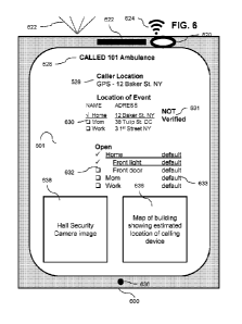
Fig. 6 is a screen shot of an emergency notification responder application in
accordance with an embodiment of the current invention. In some embodiments,
an
application may open and on a computing device 600 of emergency personnel. The
application may be coordinated with applications on other devices. For
example, an
emergency responder may be given information about the caller and/or the event
and/or conditions in the vicinity of the event. Alternatively or additionally,
an
emergency responder may be given control over conditions in the vicinity of
the event.
Alternatively or additionally, the application may serve for communication
between
emergency responders, people at the event, other involved individuals and/or
dispatchers. In some embodiments, device 600 and/or the application thereon
may be
used by a caretaker of an emergency victim and/or a superintendent at a
building
where an emergency is occurring and/or a emergency dispatcher and/or in a call
center
CA 03101308 2020-11-23
WO 2019/244149
PCT/IL2019/050677
supervising the emergency application and/or a security organization
responsible for
security at a site where there are automatic door opening devices.
In some embodiments, device 600 displays the kind of communication that
initiated the emergency call. Optionally, the location 528 from with the call
was made
is displayed. In some embodiments, the reckoned location 630 of the event is
displayed. Optionally, along with the reckoned location, in some embodiments
alternative locations 630 are displayed and/or an indicator 631 of how sure is
the
identification of the location. For example, the application may display
whether the
caller verified the location for example, by selecting and/or checking the
location on
the application running on his device. In some embodiments, a list 632 of
emergency
notification apparatuses are displayed. Optionally, along with the list of
apparatuses, it
may be displayed who activated which apparatus.
In some embodiments, further information may be made available over device
600. For example, a map 636 may be displayed. For example, the map 636 may
include directions to a building of an emergency event and/or directions to
the proper
entrance to the building and/or directions within the building to the location
of the
event. Alternatively or additionally an image 638 and/or a video image may be
shown
from a security camera in the vicinity of the event and/or from a camera of a
phone of
another user of the application (for example camera 520 of the caller who
reported the
emergency).
In some embodiments a responder device may include a microphone 636, a
light 621, a speaker 622, a camera 620 and/or a wireless communication device
624.
For example, the wireless communication device 624 may be used for
communication
with an emergency notification apparatus (e.g. to get information and/or to
activate
and/or to deactivate). For example, camera 620 and/or microphone 636 may be
used
to keep a dispatcher informed of what is going on at an emergency scene.
Fig. 7 is a block diagram of an emergency notification system in accordance
with an embodiment of the current invention. In some embodiments, a caller 754
who
reports an emergency incident has an application on his computing device that
connects coordinates information and control between various apparatuses
and/or
actors. For example, the system may be managed by an overseer 751. Optionally,
integrated applications open on devices of one or more of the callers 754,
another
individual (e.g. family member, caretaker), an emergency responder 772 (e.g.
an
EMT), staff 757 of the building or area of the emergency, and/or security
personnel
748 (e.g. police, a security service, a private security guard). Optionally, a
responder
and/or dispatcher will be notified of possible important conditions at a
location where
an emergency is occurring and/or nearby. For example, in the case of a fire,
responders may be warned that a resident of a certain apartment in the
building has an
dangerous and/or explosive object (e.g. an oxygen tank) and/or that a resident
of a
certain apartment has a breathing condition (e.g. asthma, emphysema, a heart
16
CA 03101308 2020-11-23
WO 2019/244149
PCT/IL2019/050677
condition, lung cancer) and may be highly susceptible to suffocation due to
smoke
and/or a disability requiring special evacuation assistance. A message to
responders
may give a lists of emergency equipment available in the vicinity and/or of
medical
conditions of people who are potentially involved in the emergency.
In some embodiments, a shared application may direct control by a group of
individuals over to various appliances. Optionally, the system may control one
or
more emergency notification apparatuses. For example, there may be one or more
master apparatuses 758 that are controllable through a network 753 and/or from
a
large distance. For example, network 753 may include a public network, for
example
the Internet. For example, there may be one or more secondary apparatuses 755
that
are controlled via a master apparatus 758 and/or locally using a wireless
connection
(for example, a caller 754 may have control of one or more devices in his home
building and/or a security organization 759). For example, a master apparatus
758
may include an entrance marker and/or a door opener and/or a secondary
apparatus
758 may include an entrance marker and/or a door opener. Optionally other
appliances
756 may be controlled and/or coordinated. For example, other appliances may
include
parts of a building electrical system and/or a sprinkler system and/or a
loudspeaker
system and/or a valve, for example a gas valve and/or a water valve.
Optionally, a
building alarm 770 may also be integrated into the system. In some
embodiments, a
master apparatus 758 may control personal devices of a building tenant. For
example,
a tenant with a heart condition may connect his electronic door lock to the
master
apparatus 758. For example, when an emergency responder responds to a call to
the
tenant's address, he may be supplied with a link to unlock the door of the
apartment.
Various "smart" appliances may be accessible to emergency personnel, for
example a
stove and/or indoor lights and/or outdoor lights and/or a climate control
system.
In some embodiments, a single master apparatus 758 may include a large
number of secondary apparatuses 755 in the same building and/or in other
buildings.
Optionally, a user may access one or another of the master apparatuses and/or
secondary apparatuses separately or together.
Fig. 8 is a schematic illustration of an emergency sign 800 in accordance with
an embodiment of the current invention. In some embodiments a sign may include
an
emergency symbol, for example a flashing patch of light 816. Optionally the
lights
will flash in a color and/or pattern that will tell emergency personnel what
kind of
emergency is occurring (e.g. fast red flashing for medical emergency, flashing
blue for
police call, slow red flashing for fire etc.). Optionally, an emergency sign
800 may
include a large clear address marker 812. Optionally, the address marker 812
will be
obvious and easy to read day or night (for example, it may include a LED
visible at
night and/or be shaded and/or include an LCD that is obvious during the day
and/or
the LED may be strong enough to be clearly visible in the day). Optionally, a
sign 800
may include a message area 882. For example, the message area may be used for
non-
17
CA 03101308 2020-11-23
WO 2019/244149
PCT/IL2019/050677
emergency local information (for example announcements from the local
government). In some embodiments, the message area may be used for emergency
information (for example in the case on an earthquake the sign may give
information
as to where to seek shelter and/or in the case of an air raid event the
message area may
give instructions to during an air raid event to reach a shielded portion of
the building.
The message 882 may give information for emergency personnel (for example
where
is the emergency kit in the building and/or what kind of equipment is
available). In
some embodiments a verbal message may also be broadcast by a loudspeaker
In some embodiments a sign may be embodied entirely as a single unit (for
example a LED electronic screen include a message and/or a picture of a
flashing
alarm light) and/or it may include separate parts (e.g such as an LED
electronic screen
message area and/or a separate flashing alarm light etc. ). Optionally a sign
800 may
be angled to be visible when a vehical approaches the house from a main street
and/or
a sign 800 may be shaped to be visible from multiple directions.
The foregoing description and illustrations of the embodiments of the
invention have been presented for the purpose of illustration, and are not
intended to
be exhaustive or to limit the invention to the above description in any form.
Any term that has been defined above and used in the claims, should to be
interpreted according to this definition.
The reference numbers in the claims are not a part of the claims, but rather
used for facilitating the reading thereof. These reference numbers should not
be
interpreted as limiting the claims in any form.
It is expected that during the life of a patent maturing from this application
many relevant technologies will be developed and the scope of the terms is
intended
to include all such new technologies a priori.
As used herein the term "about" refers to 10%
The terms "comprises", "comprising", "includes", "including", "having" and
their conjugates mean "including but not limited to".
The term "consisting of' means "including and limited to".
The term "consisting essentially of" means that the composition, method or
structure may include additional ingredients, steps and/or parts, but only if
the
additional ingredients, steps and/or parts do not materially alter the basic
and novel
characteristics of the claimed composition, method or structure.
As used herein, the singular form "a", "an" and "the" include plural
references
unless the context clearly dictates otherwise. For example, the term "a
compound" or
"at least one compound" may include a plurality of compounds, including
mixtures
thereof.
Throughout this application, various embodiments of this invention may be
presented in a range format. It should be understood that the description in
range
format is merely for convenience and brevity and should not be construed as an
18
CA 03101308 2020-11-23
WO 2019/244149
PCT/IL2019/050677
inflexible limitation on the scope of the invention. Accordingly, the
description of a
range should be considered to have specifically disclosed all the possible
subranges as
well as individual numerical values within that range. For example,
description of a
range such as from 1 to 6 should be considered to have specifically disclosed
subranges such as from 1 to 3, from 1 to 4, from 1 to 5, from 2 to 4, from 2
to 6, from
3 to 6 etc., as well as individual numbers within that range, for example, 1,
2, 3, 4, 5,
and 6. This applies regardless of the breadth of the range.
Whenever a numerical range is indicated herein, it is meant to include any
cited numeral (fractional or integral) within the indicated range. The phrases
"ranging/ranges between" a first indicate number and a second indicate number
and
"ranging/ranges from" a first indicate number "to" a second indicate number
are used
herein interchangeably and are meant to include the first and second indicated
numbers and all the fractional and integral numerals therebetween.
It is appreciated that certain features of the invention, which are, for
clarity,
described in the context of separate embodiments, may also be provided in
combination in a single embodiment. Conversely, various features of the
invention,
which are, for brevity, described in the context of a single embodiment, may
also be
provided separately or in any suitable subcombination or as suitable in any
other
described embodiment of the invention. Certain features described in the
context of
various embodiments are not to be considered essential features of those
embodiments, unless the embodiment is inoperative without those elements.
Although the invention has been described in conjunction with specific
embodiments thereof, it is evident that many alternatives, modifications and
variations
will be apparent to those skilled in the art. Accordingly, it is intended to
embrace all
such alternatives, modifications and variations that fall within the spirit
and broad
scope of the appended claims.
All publications, patents and patent applications mentioned in this
specification are herein incorporated in their entirety by reference into the
specification, to the same extent as if each individual publication, patent or
patent
application was specifically and individually indicated to be incorporated
herein by
reference. In addition, citation or identification of any reference in this
application
shall not be construed as an admission that such reference is available as
prior art to
the present invention. To the extent that section headings are used, they
should not be
construed as necessarily limiting.
19