Note: Descriptions are shown in the official language in which they were submitted.
STOCKINGFOOT WADER
CROSS-REFERENCE TO RELATED APPLICATION
This application claims priority back to U.S. Patent Application No.
16/016,633
filed on June 24, 2018.
BACKGROUND OF THE INVENTION
1. Field of the Invention.
The present invention relates generally to the field of fishing waders, and
more
specifically, to a stockingfoot wader with raised neoprene patterns in the
outside toe and
inside ankle areas of the bootie to improve airflow, warmth, comfort and fit.
2. Description of the Related Art.
Since at least the turn of the last century, inventors have been attempting to
solve
the problem of heat and moisture accumulation in footwear. Some of these
inventions
are described below. None of these inventions is specifically designed to be
incorporated
with a fishing wader, and none possesses the unique structural features of the
present
invention, as described more fully below.
U.S. Patent No. 757,424 (Vohl, 1904) discloses a shoe with a lining of open
texture having spacing ribs or cords to form air-channels. The lining is
comprised of a
textile fabric, and the cords or ribs are secured or fastened to the outside
surface of the
lining. The cords or ribs extend from the sole to the top of the lining and
are sized and
spaced a sufficient distance apart to keep the lining from coming into contact
with the
1
Date Recue/Date Received 2021-05-28
CA 03101630 2020-11-25
WO 2020/005461
PCT/US2019/035094
shoe when the shoe is upon a foot. The lining further comprises a stiff sole
with a metal
plate adhered to it.
US, Patent No. 3128566 (Burleson et oL, 1961) describes a ventilated hoot with
an air pump in the heel that is activated during walking. As pressure is
placed on the heel
portion of the boot, a hollow cavity in the heel portion is collapsed, thereby
forcing air to
be expelled from the cavity, to travel through various passageways within the
boot, and to
be expelled at various locations.Within the interior of the boot, As weight is
tilled, from
the heel during normal ambulatory. action, the resilient material of the
insulatien causes
the cavity to return to a normal position and fresh air to be drawn into the
cavity through
inlet passageways. This cycle is repeated during each walking step.
U.S. Patent No. 5295312 (Blumberg e tati. 1994) provides a ventilated boot or
shoe with a spongy open-celled compressible insole. The insole comprises two
pairs of
channels that are configured to allow air to enter the insole at the heel and
instep areas.
Ventilation pipes extend downwardly from the open top of the boot or shoe and
are
connected to the channels. As the wearer walks, the insole is compressed and
expels air
trapped in the open cells athe insole. As pressure on the insole cases, the
resilient insole
expands and draws air back into, itself through the ventilation pipes,
U.S. Patent Nos, 5319807 (Brier, 1994). and 5333524 (Brier, 1994) both
disclose a
moisture-management sock and Shoe in which the sock has a multi-layer moisture-
wicking channel that extends from the ankle to the toe area of the sock. The
sock further
eomprises air circulation channels that extend along opposing sides of the
moisture
-
wicking channel. The. shoe has a moisture-wicking inner liner situated
adjacent to the
2
CA 03101630 2020-11-25
WO 2020/005461 PCT/US2019/035094
tongue and the :toe box area for moving MOISttife- from the foot and through
the shoe. The
shoe and sock are designed to be worn together.
U.S.. Patent No. 5499459 (Tomato, 1996) describes. an article of footwear with
first and second replaceable booties that fit within the article of footwear.
The first bootie
comprises a waterproofing layer of material that is impervious to penetration
by water.
The second bootie comprises an. inner layer fabricated of a moisture-absorbing
and
breathable material. The booties are interchangeable and have releasable
attachment
elements for releasably securing the booties within the footwear.
Patent .No. 5708985 (Ogden, 1998) provides a sock that is knitted. with
successes courses of yarn and -that has &number of spaced ribs extending
longitudinally
'between the heel and toes The ribs are formed by knitting a selected number-
of additional
courses of yarn extending from the outer layer of the sock toward the instep
portion of the
sock.. The individual ribs are either continuous in the transverse direction,
or they are
discontinuous with transverse spaces formed alone each rib it between sections
of
stitched yarn. The longitudinal. spaces between the ribs and the transverse
spaces within
the individual ribs are of sufficient width to induce the Skin of the plantar
surface of the
foot to extend at least partially therein,, thereby enhancing the frictional
engagement of
the sock with the foot.
U,S. Patent No. 6286151 (Lambert, 2001) discloses a sock that is designed to
wick. sweat OW of a shoo. The. sock has an integrated airway that extends from
the sole to
the top of the sock. The airway is comprised a neat-regulating netted fabric.
U.S. Patent
Application Pub. No. 2006/0143801 (Lambert) discloses a sock with a
dehumidifying
3
CA 03101630 2020-11-25
WO 2020/905461
PCT1US2019/035094
channel in the sole of the sock. Air ducts are provided On the inner leg side
and/or the
outer leg side of the sock and are connected to the dehumidifying channel.
U.S. Patent No. 7392601 (Vanes et at, 2008) describes a foot covering with an
elasticized chimney structure. The chimney structure is a plurality of
chimneys that are
configured to move heat or moisture from within the foot covering out through
the collar
region of the foot covering: Each chimney is comprised of a pair of elongated
supports
and a series of distributed braces, that connect the elongated supports. The
braces are
movable from an. at-rest position to a stretched position or a compressed
position as the
.foot moves during wear.
U.S. Patent Nos. 8146266 (Vanes et at., 2012) provides an article of footwear
with a chimney structure comprised of a plurality of chimneys that define
pathways for
moving heat or moisture from within to outside the article of footwear. Each
chimney
has It pair of sidewalls. a rear wall situated between the sidewalls, and an
open side
opposite the rear wall. The open. side of the chimney faces the cavity formed
with the
article of footwear for receiving a foot and is adjacent to the foot. during
wear.
Specialized footbeds may be incorporated to evacuate hotõ moist air away from
the
underside of the foot and toward the chimneys. U.S. Patent No. 8359769 (Vattes
et.
2013) describes a number of alternate embodiments involving chimney structures
in
variOus configurations. The latter chimney structures are disposed along the
tongue
and* upper areas of the article of footwear.
U.S. Patent No. 8191284- (Cho, 2(11.2) discloses a footwear cooling system in
which thc sole of an article of footwear has two compression chambers. As -
these
chambers are compressed during the act of walking, a pressure imbalance is
created
4
CA 03101630 2020-11-25
WO 2020/905461
PCT1US2019/035094
between the two chambers, thereby causing air to be disposed along the upper
sole
portion via, apertures in the upper sole portion. Channels situated between
the
compression chambers and the apertures facilitate the passage of air from the
lower sole
to the upper sole area.
U.S. Patent No, 9226527 (Dahlgren et a, 2016) and U.S. Patent Application Pub.
No. 2014/0157491 (Dahlgren) involve socks that are. specifically designed to
transfer
moisture away from the foot. The socks comprise ribs, channels and padding,
that are
positioned to facilitate trIgistire M0\101=1E-from the interior of the sock
upwardly and
outwardly from a shoe or boot ht one embodiment., the tubular portion of the
sock has
nuiltiple tube ribs transversally positioned. and longitudinally Spaced apart
to font tube
channels. These ribs are formed with additional .yarn material and are
configured to
contact the foOt of the wearer. The invention utilizes a combination of
hydrophobic and
hydrophilic materials to further facilitate the movement of moisture.
BRIEF SUMMARY OF THE INVENTION
The present invention is a wader comprising a body portion and a bootie;
wherein
thebootie is attached to the body portion; wherein the bootie is comprised of
a toe piece,
an ankle piece, and a sole piece; wherein the toe piece, the ankle piece, and
the .5.o1e piece
are adhered together to form the bootie;:wherein the toe piece has an outside
surface!, and
the toe piece comprises a raised neoprene area on the outside surface wherein
the ankle
piece has an inside surface, and the ankle piece comprises a raised. neoprene
area on the
irOfiC surface; and wherein the toe piece, the ankle piece, and the sole piece
arc all
comprised of a neoprene material. In a preferred embodiment, the raised
neoprene area
on the inside of the ankle piece coMprises an ankle segment that. is situated
proximate the
CA 03101630 2020-11-25
WO 2020/905461 PCT/US2019/035094
ankle of a wearer when the bootie is worn; wherein the ankle segment comprises
a top
edge; wherein the raised neoprene area on the inside of the ankle piece
further comprises
a plurality of vertically oriented segments with bottom ends; wherein the
vertically
oriented segments are configured to form a fluid channel around a top area of
the ankle
segment. between the bottom ends of at. least some of the vertically oriented
segments and
the top edge of the ankle segment; and wherein the vertically oriented
segments are
configured to form vertically oriented fluid channels between the vertically
oriented.
segments.
In a preferred embodiment, the bootie has an inside With a circumference
firmed
by the ankle piece and the sole piece. and tbe-vertically oriented segments -
extend
circumferentially around an entire inside of the bootie except for that
portion of the
bootie that is formed by The sole piece. In a preferred embodiment the
vertically oriented
segments are configpmd to ibrin an arch over -a midfoot of the wearer, and the
bottom
ends of the vertically oriented segments are configured to form an arch over
an ankle
bone of the wearer. The bootie comprises an inside surface, and an entire
inside surface
of the bootie is preferably coated with an antimicrobial ehemical.
In one embodimeet, the raised.neoprene area on the outside of the toe piece is
manufactured by compression molding a single layer of neoprene material, and
the raised
neoprene are on the inside of the ankle piece is manufactured by compression
molding a
sirejle layer of -neoprene material. Preferably,, after compression of the toe
piece, the
raised neoprene area on the outside of the toe piece has a duremeter of I I
and that
portion of the single layer of neoprene material that is compressed has a
durometer of-20
using a GS-701 N type C durometer tester; and after compression of the ankle
piece, the
6
CA 03101630 2020-11-25
WO 2020/905461
PCT1US2019/035094
raised neoprene area On the inside of the ankle piece has a durometer of I I
and that
portion of the single layer of neoprene material that is compressed has a
durameterof 25
using a GS-701N type C durometer tester. Preferably,. after compression of the
toe piece,
the raised neoprene area of the too piece has a thickness of sik millimeters
and that
portion of the single layer of neoprene material that is compressal has a
thickness of four
millimeters; and after compression of the ankle piece. the raised neoprene
area of the
ankle piece has a thickness of eight millimeters and that portion of the
single layer of
neoprene material that is compressed has a thickness Of four millimeters,
In another embodiment, the raised neoprene area on. the outside of the toe
piece is
manufactured by staling a neoprene island in the form of the raised neoprene
area on
top elan underlying layer of neoprene material. adhering the neoprene island
to the
underlying layer of T*oprene= material, and adhering a layer of knit jersey
material to a
top surface of the neoprene island and the underlying layer of neoprene -
material., and the
raised neoprene area on the inside of the ankle piece is manufactured by
stacking a
neoprene island in the form of the raised-neoprene- area on top Of an
anderlying layer of
neoprene material, adhering the neoprene Wand to the underlying layer of
neoprene
material, and adhering a layer of knit jersey material to a top surface of the
neoprene
island and a top surface of the underlying layer of neoprene .material.
Preferably, both
the neoprene island and the underlying layer of neoprene material of' the toe
piece have a
durometer of II. both the neoprene Island and the underlying layer of neoprene
material
of the ankle piece have a durometer of 11, and the sole piece has a durometer
of 18 using
a CIS-701N type C durometer tester. .Preferably, the neoprene island of the
toe piece has
a thickness of two millimeters and the underlying layer of neoprene Material
of the toe
7
CA 03101630 2020-11-25
WO 2020/005461 PCT/US2019/035094
piece has a thiekneas of three millimeters; and the neoprene island of the
ankle piece .has
thickness of three millimeters and the underlying layer of neoprene material
of the
ankle piece has a thickness of three millimeters.
In a preferred eiTtbodirrtent, the raised neoprene area. on the outside
surface of the
toe piece comprises a lateral portion that extends laterally across a front of
the toe area,
two extensions extendingemrwartily from a center part of the lateral portion,
and two
;kings that. are. parallel to and situated outside of each of the two
rearwardly extending
extensions; and the lateral portion, rearwerdly extending extensions and wings
art all
interconnected.
BRIEF DESCRIPTION OF THE DRAWINGS
Figure .1. is a perspective view of the present invention.
Figure 2A is a perspective view of the bootie of the present invention..
Figure 2/1 is a longitudinal section view of the bootie Shown in Figure 2A.
Figure 3A is-a perspective view of the txx)tie shown with the bootie turned
inside
-
out.
Figure 313 isa longitudinal section view of the bootie shown in Figure 3A.
Figure 4A is a pattern view of the toe piece before compression molding.
Figure 413 is a pattern view of the press tool used to form the molded toe
piece.
Figure 4C is a pattern view of the toe piece after compression :molding..
Figure 5A is a pattern view of the ankle piece before compression molding.
Figure 513 is a pattern view of the press too/ used to form the 'molded ankle
piece.
Figure 5C. is a pattern view of the ankle piece after compression molding.
Figure 6 is a pattern view of the sole piece.
8
CA 03101630 2020-11-25
WO 2020/005461
PCT/US2019/035094
Figure 7 is a pattern-view of the toe.island used in the stack up
manufacturing
method.
Figure 8 is a pattern. view of the ankle. island used in the stock-up
manufacturing
method.
Figures 9-14 illustrate the compression molding method of manufacturing the
present invention.
Figure 9 is a section view of the tee piece of the bootie shown in relation to
the
press tool but bethre the toel comes into contact with the toe piece.
'Figure 10 is a section view of the toe piece of the bootie shown in relation
to the
press WI during the compression step..
Figure Ills a section view of the toe piece of the bootie shown with the press
tool
being removed after compression.
Figure 12. is a section view of the ankle piece of the bootie shown in
relation to
the press tool but before the tool comes into contact with the ankle piece.
Figure 13 is a section view of the ankle piece of the bootie shown in relation
to
the press tool during the compression Step.
Figure. 14 is a section view-of-the ankle piece of the bt,letie shown with the
press
tool being removed after compression.
Figures 15-26 illustrate the stack-up method of manufacturing the present
invention.
Figure 15 is an exploded view of the toe piece of the 'bootie shown prior to
assembly.
9
CA 03101630 2020-11-25
WO 2020/005461 PCT/US2019/035094
Figure 16 isa section View of the flat heat press positioned above the
neoprene
island and the underlying neoprene layer.
Figure 17 is a. section view of the toe piece of the bootie shown with the
flat heat
press in contact with the neopiene layers but with the knit layer omitted.
Figure 18 is a section view of the toe piece of the bootie Shown with the
press tool
(in the %fin of a female mold) positioned above the neoprene island and the
underlying.
neoprene layer with the knit jersey fabric situated between the press tool and
the
neoprene layers.
Figure 19 is a section view of the toe piece of the bootie shown with the.
press tool
in contact with the knit jersey layer.
Fig= 20 is a section view of the toe piece of the bootie shown with the press
tool
being, removed after the final a.dhesive step.
'Figure 21 is an exploded view of the toe. piece Of the bootie shown prior to
assembly.
Figure 22 is a sectiOn view of the flatheat.press positioned above the
neoprene
island. and the underlying neoprene- layer.
Figure 23 is a section view of the toe piece of the bootie shown with the flat
heat
press in contact with the neoprene layers but with the knit layer omitted.
Figure 24 is a section view of the toe piece of the bootie shown with the
press tool
(in the form of a female mold) positioned above the neoprene ishmd and the
underlying
neoprene layer with the knit jersey fabric situated between the press tool and
the
neoprene layers,
CA 03101630 2020-11-25
WO 2020/005461
PCT/US2019/035094
Figure 25 s a aeetion view of the toe piece of the hootie.Sbown With the press
toot
in contact with the knit jersey
Figitre 26 is a section view of the toe piece of the bootie shown with. the
presa toot
being removed. after the final adhesive geps
REFERENCE NUMBERS
Wi141VT:
A
4 Body .portion
gootle
4 Toe piece:
Ankle piece:
Sole piece
7 Tape
8: Seam
:9 Raised neoprene area (on outside of roe piece)
Raised neoprene area (on inside of ankle:ipieee)
11 Ankle segment
12 Vertically oriented segment
13 Fluid channel (between ankle segment and vertically oriented
segments)
14 fluid channel: (vertically oriented)
Press tool (toepece cut-ont)
16 Ness tool (ankle *0e ent-ont)
17 Toe island
18 :Ankle isi4pd.
11
CA 03101630 2020-11-25
WO 2020/905461
PCT/US2019/035094
19 jersey material
20a Hat heat press
20b Press tool (female mold)
DETAILED DESCRIPTION OF INVENTION
The term "stockingfoot" refers to a fishing wader in which the bootie (or
foot) of
the wader fits inside of .a fishing (or wading) boot. Stockingibot waderi
offer versatility
in that the wading boot can also act as a hiking hoot when -it is necessary to
hike into. a
fishing spot, and they may be worn with different types of wading boots (felt
sole, rubber
sole, studded, etc). The alternative to stockingfoot waders are bootfoot
waders, in which
the fishing boot is attached to the wader. Bootfoot waders are preferred for
widwater
fishing and by surfcasters and saltwater anglers, where there is a greater
chance of salt
and grit getting into the boot than in. ordinary fishing conditions; they are
also considered
to be warmer than stmkingfoot waders. Stockingfoot waders, on the other hand,
are
considered by some to be easier to put on, easier to pack away, and generally
preferred
for all other fishing situations. Stockingloot Waders combined with a lack-up
boot
provide greater ankle support than a bootfoot wader and are typically better
for miles of
walking.
Stockingibot waders may be Made with neoprene, which is a non-breathable
material, or with breathable materials such as GORE-TM: fabric. Even on
breathable
waders, however, the bootie (or foot) of the wader is usually ma.dewith
neoprene because
of its d.urability, stretch, cushioning, and insulative properties. Although
neoprene
booties keep the wearer's feet warm and prevent water ingress, they also trap
moisture
due to perspiration. Excess perspiration in the bootie will rob the feet of
precious heat
12
CA 03101630 2020-11-25
WO 2020/905461
PCT/US2019/035094
The present invention is designed- to solve this problem by providing channels
through
which moist= is wicked up and out of the bootie¨through the shaft of the
bootie and
up into the breathable section of the wader. The. present invention also
provides added
protection for the bootie seams and cushioning in the top. of foot area to
prevent wear.
The invention also has been designed to add earn Fort to the user by providing
mote
'mom= in certain aneas. in addition, the added neoprene provides more
insulation to
keep the foot warmer. The present invention takes into consideration the
relative
thickness and durometer of various neoprene layers to achieve optimal
performance
The present invention incorporates both an internal set of channels that are
built
into the bootie starting at the ankle level and extending upward toward the
top of the
bootie and a configuration of channels that are formed by a raised section of
neoprene
that is situated on top of the outside of the front portion of the bootie
(directly above the
foot). The internal channels are specifically configured to move moisture
vertically .up
the shaft of the bootie, which tdlowsfor greater airflow within the bootie.
These
channels work with the natural motion of the feet to push heavily moisture-
laden air up
-through the shaft more effectively: once within the breathable portion of the
wader
(which begins mid-calf), this moisture will dissipate and leave the wader,
The -second set of channels (on the outside of the bootie) is designed to
create a.
separation between the bootie and the inside of the wading boot, thereby
reducing wear
and tear on the bootie, especially in the. top of foot area. This raised
neoprene area
provides greater comfort at the top of the tbotarea when the laces ().f the
wading boot
(overlying the bootie) are tightened.
13
CA 03101630 2020-11-25
WO 2020/905461 PCT/US2019/035094
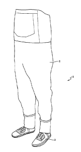
Figure 1 is a perspective view of the present invention. As shown in this
figure,
the invention is a fishing wader 1 comprised clif a. body portion 2 and a
bootie 3. The
bootie, is attached to the body pertion 2 with an adhesive. The novelty of the
present
invention relates to the construction of the bootie 3 and not to the body
portion 2 or the
Method by which the bootie 3 is attached to the body portion 2.
Fiore 2A is a perspective view of the bootie of the present invention. Asshown
in this figure, the bootie 3 is comprised of three parts. The first part is
the toe piece 4, the.
second part of the ankle piece 5, and the third part is the sole piece 6.
These three pieces
are all comprised of neoprene material., and they are all preferably of the
same thickness
(except for the raised neoprene areas). They are adbered (glued) together
along their
edges to Om the bootie shape shown in Figure:2A. Tape 7 suitable for this
purpose is
then applied along all of the joined edges, which form seams 8. In. the
figures, the seams
$ are shown with dotted. lines. Them are no stitched seams anywhere on the
bootie.
Figure 2A also shows the raiSed neoprene area 9 on the outside of the -toe
piece 4. The
raised neoprene area 9 may be formed in one of two ways, as described below.
Figure 211 is a longitudinal section view of the bootie shown in Figure 2A.
.As
shown in this figureethe bootie 3 also comprises a raised neoprene area 10 on
the inside
of the ankle piece 3. This raised neoprene area 10 is also formed in one of
two ways., as
described below. The raised neopnene area 10 comprises an ankle segment 11
that is
situated proximate the ankle of the wearer when the bootie 3 is worn.
(Although the
ankle segment 11 is Shown here as being oval in shape, the present. invention
is not
limited to an -oval.etheped ankle segment 11.) The raised neoprene area 10
also comprises
a plurality of vertically oriented segments 12, which are configured to form a
.fluid
14
CA 03101630 2020-11-25
WO 2020/905461
PCT1US2019/035094
channel 13 around the top area of the ankle segment 11 (between the bottom
ends of at
least some of the vertically oriented. segments 12 and the top edge of the
ankle segment
11). and vertically oriented fluid channels 14 between the vertically oriented
segments 12.
Moisture from the foot area. is wicked upward. and into the breathable body
pertion 2 of
the wader 1 whenthe wader is worn. The particular configuration of the
vertically
oriented segments .12, separated by vertically, oriented thdd channels 14,,
provides greater
flexibility (foldability) around the ankle area of the bootie. It .also
provides a better fit
around the ankle area.
Figure 3A is a perspectiveview of the bootie shown with the bootie turned
inside
out. Each bootie. comprises two ankle segments 11 (one on either side of the
wearer's
ankle). The vertically oriented segments 12 extend circumferentially all of
the way
around the inside of the bootie except for that portion of the bootie that is
formed by the
sole piece 6. Note also that the vertically oriented segments 12 are
configured to form an
arch over the midfoat (see also Via. 5C). The bottom ends of the vertically
oriented
segments 12 are configured to form an arch over -the ankle bone of the wearer.
In. a.
preillred embodiment, the entire inside. surface of the bootie is coated with
an
-antimicrobial chemical such as M1CROBANIm spray disinfectant, to reduce odor.
Figure 313 isa longitudinal section view of the bootie shown in Figure 3k As
shown in this figure and Figure 2B, the seams 8 are preferably taped 7 on both
the inside
and the outside of each seam S. The sole piece 6 forms the sole of the bootie
and a rear
panel of 'the bootie that extends upward from the rear end of the sok to the
top rear edge
of the bootie. The toe -piece 4 surrounds the top of the foot forward of the
ankle (except
CA 03101630 2020-11-25
WO 2020/905461
PCT/US2019/035094
for the sole). The ankle piece 5 surrounds the ankle area circumferentially
except for-the
rear panel formed by the sole piece 6.
in one method. of construction, the raised neoprene areas 9, lt) of the toe
and
ankle pieces 4, 5 are made by compressing a single layer of neoprene to form.
the raised
neoprene areas. This method is illustrated in Figures 4A-4C.
Figure 4A-is a. pattern view of the toe piece before compression molding. The
toe
piece 4 is preferably comprised of a single layer of neoprene material with a
layer of
nylon jersey fabric adhered to one side of the layer of neoprene material and
a layer of
power Stretch polyester Jerky fabric adhered to the other side of the layer of
neoprene
material. (See Figures 941. below.) The toe piece 4 is preferably shaped as
shown in
Figure 4A.
Figure 4B is a pattern view of the press tool used to form the molded toe
piece.
The press tool 1.5 is a sheet of metal out of which is cut the pattern for the
raised
neoprene area 9.
Figure 4C is a pattern view of the toe piece after compression molding. The
compression molding method is illustrated in Figures 9-1.1.
Figure 5eli is a pattern, view of the ankle piece before compression molding.
The
ankle piece 5 is preferably oomprised of a single layer of neoprene material
with a layer
of nylon jersey fabric adhered to one side of the layer of neoprene material
and a layer of
power stretch polyester jersey &brie- adhered to the other side of the layer
of neoprene
material. (See Figures 12-14 below.) The ankle piece 5. is preferably shaped
as shown in
Figure SA.
16
CA 03101630 2020-11-25
WO 2020/005461
PCT/US2019/035094
Figure 513 is a pattern view of the press tool used to :form the molded ankle
piece.
The press tool 16 is a sheet of metal out of which is cut the pattern for the
raised
neoprene area 10.
Figure 5C is a pattern view of the ankle piece aller compression molding. The
compression molding method is illustrated in Figures 1.2-14.
Figure is a pattern view of the .sole piece. This figure shows the part of the
sole
piece 6 that forms the sole of the. bootie (left part of the figure) and the
part of the sole
piece 6 that forms the rear panel of the bootie (right part of the figure).
The rear panel is
situated. proximate to the Achilles tendon of the foot when the bootie is
worn.
Figure 7 is a pattern view of the toe island used in the stack-up
manufacturing
method in an alternate construction method, the raised neoprene area .9 on the
toe piece
4 is formed by stacking a toe Wand 17 on top of an underlying layer of
neoprene
material. The toe island is a layer of neoprene material that has been cut
into the shape of
the raised neoprene area 9. In a mferred embodiment, the raised neoprene area
9 tin
both the Compression method and the stack-up method) comprises a lateral
portion 17a
that extends laterally across a front of the toe area, two extensions 17b
extending
rearwardly from a center part of the lateral portion, and two wing.s17c that
are parallel to
and .situated outside of each of the two rearwardly extending extensions 17h.
In a
preferred. embodiment, the lateral portion 17a, rearwardly extending
extensions 1717 and
wings 17c are all interconnected.
Fig= 8 is a pattern view of the ankle island used in the stock-up
manufacturing
method. The ankle island 18 forms the raised neoprene area 10 on the interior
of the
17
CA 03101630 2020-11-25
WO 2020/005461
PCT/US2019/035094
ankle piece 5. The particular-configuration of the raised neoprene area 10 has
been
previously -described.
Figures 9-14.illustrate the compression molding method of manufacturing the
present invention, This method of construction is easier to perform and less
costly than
the stack-up method described in subsequent figures.
Figure 9 is a section view of the toe piece of the bootie shown in relation to
the
press tool but before the tool comes into contact with the toe piece. As
mentioned above,
the neoprene layer coaSists of a layer of nylon jersey fabric adhered to the
underside
(bottom) Otte neoprene material and a layer of power stretch polyester jersey
fabric
adhered to the top surface- of the neoprene material The thickness of the.
neoprene layer
is preferably six (6) millimeters (mm ) (including the jersey and polyester
layers).
.Figure 10 is a section. view of the-toe piece of the bootie shown in relation
to the
press tool (luring the compression step. In this step, that part of the
neoprene layer that
forms the raised neoprene area 9 is not compressed, but the remaining part of
the
neoprene layer is compressed down to 4 thickness of four (4) mm by the press
tool 15,
which is applied for twenty (20) minutes at 316 pounds per square inch ("psi")
and a
temperature of $25 degrees Fahrenheit
Figure 11 is a. section view of the toe piece of the bootie shown with. the
press tool
being removed eller compression. There is no. cooling step with the
compression
.method, as there is with the stack-up method.
Figure 12 is a section view of the ankle piece of the bootie Shown in relation
to
the press tool but before the tool comes into contact with the ankle piece. As
with the -we
.pieee, the neoprene layer. consists of a layer of nylon jersey fabric adhered
to the
18
CA 03101630 2020-11-25
WO 2020/905461
PCT/US2019/035094
underside (bottom) of the neoprene material and a layer of power streteh
polyester jersey
fabric adhered to the top surface of the neoprene material. The thickness of
the neoprene
layer is preferably eight (8) mm (including the jersey and polyester layers).
Figure 13 is a section view of the ankle piece of the bootie shown in relation
to
the press tool during the compression step. In this step, that part of the
neoprene layer
that forms the raised neoprene area 10 is not compressed, but the remaining
part of the
neoprene-layer is compressed down to a thickness of four (4) mm by the press
tool 16,
which is applied for twenty- (20) minutes at 33.6 psi and a temperature of 325
degrees
Fahrenheit.
Figure 14 is a section view of the snide piece of the bootie shown with the
press
tool being removed after compression. There is no cooling step with the
Compression
method, as there is with the stack-up method.
In a preferred embodiment, the neoprene layer that forms the toe piece has a
durometer of eleven (ll) using a GS-701N type C darometer tester prior to
compression.
The raised neoprene aNa 9, which is not compressed, retains this same
durometer; the
compressed. area of the toe.piece, however, has a durometer of twenty (20)
using, this
same durometer test. In a preferred embodiment, the neoprene layer that fo.mis
the snide
piece has adurometer of eleven (11) using a GS-701N. type C durtnneter tester
prior to
compression. The raised neoprene area 10, which is not compressed, retains
this same
durometer; the compressed area of the ankle piece, however, has a durometer of
twenty-
five (25) using this same durometer test.
Figures 15-26 illustrate the stack-up method of -manufacturing the present
invention. With this method, the Wands 17, 18 are preferably first adhered to
a flat sheet
19
CA 03101630 2020-11-25
WO 2020/005461
PCT/US2019/035094
of neoprene (together with the Overlying knit jetsey fabric.), and then the
entire stack is
die cut to .firm the toe and ankle pieces 4, 5.
Figure 15 is an exploded view of the toe piece of the bootie shown prior to
Assembly, This construction method begins with two layers of neoprene
material. Each
layer of neoprene material has a layer of nylon jersey fabric adhered to the
underside
(bottom) of the neoprene material and a layer of nylon jersey &brie adhered to
the top
surface of the neoprene .material. as shown. In a preferred embodiment, the
thickness of
the lop neoprene layer is two (2) mm, and. the thickness of the bottom
neopnene layer is
three (.3) mm. (including the fabric layers in each case). Overlying both
neoprene layers is
a layer of knit jersey fabric 19 (78% nylon and 22% spandex). The purpose of
the -knit
jersey fabric 19 is to further secure the.toe island 17 on rep of the
underlying neoprene
layer and to present a more finished look. When fully assembled, the toe
island 17 is
placed directly on top of the underlying neoprene. layer, and the knit jersey
fabric 19 is
placed on top of both the toe. island 17 and the underlying neoprene layer.
Figure 16 is a section view of the flat heat press positioned above the
neoprene
island and the underlying neoprene layer, Figure 17 is a section view of the
toe piece of
the bootie shown with the flat heat press in contact with the neoprene layers
but with the
knit layer omitted. In this step, the toe- island 17 is bonded onto the
underlying neoprene
layer with -a. flat heat press 208, which is applied tbr sixty (S0) seconds at
ten (10) psi and
260 degrees Fahrenheit. The flat, heat. press 20a activates an adhesive that
is Applied
between the two neoprene layers. It does not appreciably compress either of
the
neoprene layers.
CA 03101630 2020-11-25
WO 2020/905461 PCT1US2019/035094
Figure 18 is a -section view of the toe piece of the bootie shown with the
press tool
(in the film of a female mold) positioned above the neoprene island and the
underlying
neoprene layer with the knit jersey fabric situated between the press tool and
the
neoprene layers. Figure 19 is a section view of the toe piece of the bootie
shown with the
press tool in contact with the knit jersey layer: in this step, the knit
jersey layer is placed
over the top of the two neoprene layers (now bonded to each other), and a
press tool 20b
in form of .a female mold 20b is applied for sixty (60) seconds at ten (10)
psi and 260
degrees Fahrenheit. The press toot 20b activates an adhesive that is applied
between the
knit jersey layer and the top surface of the two stacked neoprene layers.
'Neither this nor
.the preceding step affects the durometer of either of the neoprene layers.
Figure 20 is a section view of the, toe piece of the bootie shown with the
press tool
being removed after the final adhesive step. After this step, the same press
tool 20b Is
cooled to ambient temperature and applied, to the neoprene stack-up for thirty
seconds at
psi, which allows the adhesive to stabilize.
Applying the stack-up method, the ankle -piece is made in the same manner as
the
toe piece, except that the neoprene layer ibt the ankle island is preferably
three (3) mm
thick rather than two (2) mm. thick.. Otherwise, the process is the same, as
illustrated in.
Figures 21-26.
In a preferred. embodiment, the two neoprene layers that form the toe and
ankle
pieces (that is, both the neoprene island and the underlying layer of neoprene
material)
each has a durometer of eleven (11) using a GS-701N type C durometer tester.
The
neoprene layer that forms the sole piece has a durometer of eighteen (18)
using the same
21
CA 03101630 2020-11-25
WO 2020/005461
PCT/US2019/035094
durometer test. Thus, the compressiOn method result in the non-raised areas of
the toe
and ankle pieces having a higher durotneter than with the stack-up method.
Although the preferred embodiment of the present invention has been shown and
described, it will be apparent to those skiihui hi the art that many changes
and
modifications may be made without departing from the invention in its broader
aspects.
The appended claims are theretbre intended to cover ail such changes and
modifications
as fall within the true spirit and scope of the invention.
22