Note: Descriptions are shown in the official language in which they were submitted.
CA 03102226 2020-12-01
WO 2019/236367
PCT/US2019/034556
ROLLING DIAPHRAGM SYRINGE WITH PISTON ENGAGEMENT PORTION
CROSS-REFERENCE TO RELATED APPLICATIONS
[0001] This application claims priority to United States Provisional
Application No.
62/680,304, filed June 4, 2018, the disclosure of which is hereby incorporated
by reference in
its entirety.
BACKGROUND OF THE DISCLOSURE
Field of the Disclosure
[0002] The present disclosure is related to syringes for use in the medical
field and, more
particularly, to syringes having a flexible sidewall and a piston engagement
portion
configured for engaging with an engagement mechanism of a piston of a fluid
injector. The
present disclosure particularly relate to configurations of a piston
engagement portion of a
syringe for improved engagement with engagement elements of a piston of a
fluid injector.
Description of Related Art
[0003] In many medical diagnostic and therapeutic procedures, a medical
practitioner, such
as a physician, injects a patient with one or more medical fluids. In recent
years, a number of
injector-actuated syringes and powered fluid injectors for pressurized
injection of medical
fluids, such as a contrast solution (often referred to simply as "contrast" or
"contrast
medium"), a flushing agent, such as saline, and other medical fluids, have
been developed for
use in procedures such as angiography, computed tomography (CT), ultrasound,
magnetic
resonance imaging (MRD, positron emission tomography (PET), and other imaging
procedures. In general, these fluid injectors are designed to deliver a preset
amount of fluid at
a preset pressure and/or flow rate.
[0004] Typically, powered fluid injectors have at least one piston that is
configured to
connect to a plunger disposed within the syringe. The syringe generally
includes a rigid barrel
with the plunger being slidably disposed within the rigid barrel. The piston
of the fluid
injector drives the plunger in a distal direction relative to a longitudinal
axis of the barrel to
deliver the fluid from the syringe barrel and in the proximal direction to
draw fluid into the
syringe barrel.
[0005] Syringes used in the medical field are typically disposable and are
discarded after
one use. Although disposable syringes are typically made by mass production
methods such
as injection molding, such disposable syringes are relatively expensive due to
the type and
quantity of materials and precision involved in their manufacture, and the
economic costs
1
CA 03102226 2020-12-01
WO 2019/236367
PCT/US2019/034556
associated with packaging, shipping, and storage. Accordingly, it remains
desirable to
develop improved designs of syringes to facilitate injection procedures.
SUMMARY OF THE DISCLOSURE
[0006] The present disclosure generally relates to syringes for use in the
medical field and
to methods of forming and using such syringes. The syringes may be useful in
fluid delivery
applications. The present disclosure further relates to fluid injectors having
an engagement
mechanism for engaging a piston engagement portion of a syringe.
[0007] In some embodiments of the present disclosure, a rolling diaphragm
syringe may
have a proximal end having an end wall, a distal end having an open-ended
discharge neck, a
sidewall extending between the proximal end and the distal end along a
longitudinal axis, and
a piston engagement portion protruding proximally from a central portion of
the end wall.
The piston engagement portion may have a central axis, and a plurality of
grooves recessed
inward relative to an outer surface of the piston engagement portion and
spaced apart from
each other in a direction about the central axis. At least a portion of the
sidewall may be
flexible such that the sidewall rolls upon itself with an outer surface of the
sidewall at a
folding region being folded in a radially inward direction when acted upon by
an external
force in a direction from the proximal end toward the distal end. The sidewall
may be further
configured to unroll such that the outer surface of the sidewall at the
folding region is
unfolded in a radially outward direction when acted upon by the external force
in a direction
from the distal end toward the proximal end.
[0008] In some embodiments of the present disclosure, the plurality of grooves
may be
spaced apart at equal or unequal intervals along the outer surface of the
piston engagement
portion in the direction about the central axis. The plurality of grooves may
have equal or
unequal width measured along the outer surface of the piston engagement
portion in the
direction about the central axis. The plurality of grooves may have equal or
unequal depth
measured from the outer surface of the piston engagement portion in a
direction toward the
central axis. Each groove may have a base and a pair of side surfaces
extending from the base
to the outer surface of the engagement portion. The plurality of grooves may
be continuous
over a longitudinal length of the piston engagement portion in a direction
along the central
axis. At least one of the plurality of grooves may be discontinuous over a
longitudinal length
of the piston engagement portion in a direction along the central axis.
[0009] In some embodiments of the present disclosure, an outer diameter of the
piston
engagement portion may be uniform or non-uniform in a direction along the
central axis. An
outer diameter of the piston engagement portion may decrease from a distal end
of the piston
2
CA 03102226 2020-12-01
WO 2019/236367
PCT/US2019/034556
engagement portion toward a proximal end of the piston engagement portion. In
other
embodiments, the outer diameter of the piston engagement portion may be
greater at the
distal and proximal ends along the longitudinal axis than at the middle of the
piston
engagement portion. In other embodiments, the outer diameter of the piston
engagement
portion may be greater at the proximal end than along the rest of the
longitudinal axis of the
piston engagement portion. The piston engagement portion may be monolithically
formed
with the end wall.
[0010] In some embodiments of the present disclosure, the piston engagement
portion may
be configured for engagement with at least one engagement element of a piston
of a fluid
injector at least during movement of the piston in a proximal direction. At
least a portion of
the piston engagement portion may be plastically or elastically deformed when
engaged with
the at least one engagement element of the piston. The piston engagement
portion may have a
widened portion at a proximal end, and the plurality of grooves may be
recessed at least into
the widened portion. The end wall may be concave and have a continuously
increasing
thickness in a direction toward the longitudinal axis. The central axis of the
piston
engagement portion may be coaxial with the longitudinal axis. The rolling
diaphragm syringe
may be in a first state where the end wall is inverted inwardly and rolled
toward the distal end
such that an internal volume of the rolling diaphragm syringe may be empty of
fluid.
[0011] In some embodiments of the present disclosure, a syringe assembly for a
fluid
delivery system may have a pressure jacket having a pressure jacket distal
end, a pressure
jacket proximal end, and a throughbore extending between the pressure jacket
distal end and
the pressure jacket proximal end along a longitudinal axis. The syringe
assembly further may
have a rolling diaphragm syringe disposed within the throughbore of the
pressure jacket. The
rolling diaphragm syringe may have a proximal end having an end wall, a distal
end having
an open-ended discharge neck, a sidewall extending between the proximal end
and the distal
end along a longitudinal axis, and a piston engagement portion protruding
proximally from a
central portion of the end wall. The piston engagement portion may have a
central axis and a
plurality of grooves recessed inward relative to an outer surface of the
piston engagement
portion and spaced apart from each other in a direction about the central
axis. At least a
portion of the sidewall may be flexible such that the sidewall rolls upon
itself with an outer
surface of the sidewall at a folding region being folded in a radially inward
direction when
acted upon by an external force in a direction from the proximal end toward
the distal end.
The sidewall may be further configured to unroll such that the outer surface
of the sidewall at
the folding region is unfolded in a radially outward direction when acted upon
by the external
3
CA 03102226 2020-12-01
WO 2019/236367
PCT/US2019/034556
force in a direction from the distal end toward the proximal end. The syringe
assembly further
may have a movable closure for selectively enclosing at least a portion of the
distal end of the
rolling diaphragm syringe within the pressure jacket. The pressure jacket
proximal end may
have a connection interface for releasably connecting to a fluid injector.
[0012] In some embodiments of the present disclosure, a rolling diaphragm
syringe may
have a piston engagement portion protruding proximally from an end wall. The
piston
engagement portion may have a central axis and a plurality of grooves recessed
inward
relative to an outer surface of the piston engagement portion and spaced apart
from each
other in a direction about the central axis. The piston engagement portion may
be configured
for engagement with at least one engagement element of a piston of a fluid
injector at least
during movement of the piston in a proximal direction. At least a portion of
the piston
engagement portion may be plastically or elastically deformed when engaged
with the at least
one engagement element of the piston.
[0013] In some embodiments of the present disclosure, the plurality of grooves
may be
spaced apart at equal or unequal intervals along the outer surface of the
piston engagement
portion in the direction about the central axis. The plurality of grooves may
have equal or
unequal width measured along the outer surface of the piston engagement
portion in the
direction about the central axis. The plurality of grooves may have equal or
unequal depth
measured from the outer surface of the piston engagement portion in a
direction toward the
central axis. Each groove may have a base and a pair of side surfaces
extending from the base
to the outer surface of the engagement portion. The plurality of grooves may
be continuous
over a longitudinal length of the piston engagement portion in a direction
along the central
axis. At least one of the plurality of grooves may be discontinuous over a
longitudinal length
of the piston engagement portion in a direction along the central axis.
[0014] In some embodiments of the present disclosure, an outer diameter of the
piston
engagement portion may be uniform or non-uniform in a direction along the
central axis. An
outer diameter of the piston engagement portion may decrease from a distal end
of the piston
engagement portion toward a proximal end of the piston engagement portion. In
other
embodiments, the outer diameter of the piston engagement portion may be
greater at the
distal and proximal ends along the longitudinal axis than at the middle of the
piston
engagement portion. In other embodiments, the outer diameter of the piston
engagement
portion may be greater at the proximal end than along the rest of the
longitudinal axis of the
piston engagement portion. The piston engagement portion may be monolithically
formed
with the end wall. The end wall may be concave and has a continuously
increasing thickness
4
CA 03102226 2020-12-01
WO 2019/236367
PCT/US2019/034556
in a direction toward the longitudinal axis. The piston engagement portion may
have a
widened portion at a proximal end, and the plurality of grooves may be
recessed at least into
the widened portion.
[0015] Various other aspects of the present disclosure are recited in one or
more of the
following clauses:
[0016] Clause 1. A rolling diaphragm syringe comprising: a proximal end having
an end
wall; a distal end having an open-ended discharge neck; a sidewall extending
between the
proximal end and the distal end along a longitudinal axis; a piston engagement
portion
protruding proximally from a central portion of the end wall, the piston
engagement portion
having a central axis; and a plurality of grooves recessed inward relative to
an outer surface
of the piston engagement portion and spaced apart from each other in a
direction about the
central axis, wherein at least a portion of the sidewall is flexible such
that: the sidewall rolls
upon itself with an outer surface of the sidewall at a folding region being
folded in a radially
inward direction when acted upon by an external force in a direction from the
proximal end
toward the distal end, and the sidewall unrolls with the outer surface of the
sidewall at the
folding region being unfolded in a radially outward direction when acted upon
by the external
force in a direction from the distal end toward the proximal end.
[0017] Clause 2. The rolling diaphragm syringe according to clause 1, wherein
the
plurality of grooves are spaced apart at equal or unequal intervals along the
outer surface of
the piston engagement portion in the direction about the central axis.
[0018] Clause 3. The rolling diaphragm syringe according to clause 1 or 2,
wherein the
plurality of grooves have equal or unequal width measured along the outer
surface of the
piston engagement portion in the direction about the central axis.
[0019] Clause 4. The
rolling diaphragm syringe according to any of clauses 1 to 3,
wherein the plurality of grooves have equal or unequal depth measured from the
outer surface
of the piston engagement portion in a direction toward the central axis.
[0020] Clause 5. The rolling diaphragm syringe according to any of clauses 1
to 4,
wherein each groove has a base and a pair of side surfaces extending from the
base to the
outer surface of the engagement portion.
[0021] Clause 6. The
rolling diaphragm syringe according to any of clauses 1 to 5,
wherein the plurality of grooves are continuous over a longitudinal length of
the piston
engagement portion in a direction along the central axis.
CA 03102226 2020-12-01
WO 2019/236367
PCT/US2019/034556
[0022] Clause 7. The rolling diaphragm syringe according to any of clauses 1
to 5,
wherein at least one of the plurality of grooves is discontinuous over a
longitudinal length of
the piston engagement portion in a direction along the central axis.
[0023] Clause 8. The rolling diaphragm syringe according to any of clauses 1
to 7,
wherein an outer diameter of the outer surface of the piston engagement
portion is uniform in
a direction along the central axis.
[0024] Clause 9. The rolling diaphragm syringe according to any of clauses 1
to 7,
wherein an outer diameter of the outer surface of the piston engagement
portion is non-
uniform in a direction along the central axis.
[0025] Clause 10. The rolling diaphragm syringe according to clause 9, wherein
an outer
diameter of the outer surface of the piston engagement portion decreases from
a distal end of
the piston engagement portion toward a proximal end of the piston engagement
portion.
[0026] Clause 11. The rolling diaphragm syringe according to clause 9, wherein
an outer
diameter of the outer surface of the piston engagement portion is greater at
the distal end and
proximal end than in the middle of the piston engagement portion along the
central axis.
[0027] Clause 12. The rolling diaphragm syringe according to clause 9, wherein
an outer
diameter of the outer surface of the piston engagement portion is greater at a
proximal end of
the piston engagement portion than along a remaining portion of the diameter
of the piston
engagement portion.
[0028] Clause 13. The rolling diaphragm syringe according to any of clauses 1
to 12,
wherein the piston engagement portion is monolithically formed with the end
wall.
[0029] Clause 14. The rolling diaphragm syringe according to any of clauses 1
to 13,
wherein the piston engagement portion is configured for engagement with at
least one
engagement element of a piston of a fluid injector at least during movement of
the piston in a
proximal direction.
[0030] Clause 15. The rolling diaphragm syringe according to any of clauses 1
to 14,
wherein at least a portion of the piston engagement portion is plastically or
elastically
deformed when engaged with the at least one engagement element of the piston.
[0031] Clause 16. The rolling diaphragm syringe according to any of clauses 1
to 15,
wherein the piston engagement portion has a widened portion at a proximal end,
and wherein
the plurality of grooves are recessed at least into the widened portion.
[0032] Clause 17. The rolling diaphragm syringe according to any of clauses 1
to 16,
wherein the end wall is concave and has a continuously increasing thickness in
a direction
toward the longitudinal axis.
6
CA 03102226 2020-12-01
WO 2019/236367
PCT/US2019/034556
[0033] Clause 18. The rolling diaphragm syringe according to any of clauses 1
to 17,
wherein the central axis of the piston engagement portion is coaxial with the
longitudinal
axis.
[0034] Clause 19. The rolling diaphragm syringe according to any of clauses 1
to 18,
wherein the rolling diaphragm syringe is in a first state where the end wall
is inverted and
rolled inwardly toward the distal end such that an internal volume of the
rolling diaphragm
syringe is empty of fluid.
[0035] Clause 20. A syringe assembly for a fluid delivery system, the syringe
assembly
comprising: a pressure jacket having a pressure jacket distal end, a pressure
jacket proximal
end, and a throughbore extending between the pressure jacket distal end and
the pressure
jacket proximal end along a longitudinal axis; and a rolling diaphragm syringe
disposed
within the throughbore of the pressure jacket, the rolling diaphragm syringe
comprising: a
proximal end having an end wall; a distal end having an open-ended discharge
neck; a
sidewall extending between the proximal end and the distal end along a
longitudinal axis; a
piston engagement portion protruding proximally from a central portion of the
end wall, the
piston engagement portion having a central axis; and a plurality of grooves
recessed inward
relative to an outer surface of the piston engagement portion and spaced apart
from each
other in a direction about the central axis, wherein at least a portion of the
sidewall is flexible
such that: the sidewall rolls upon itself with an outer surface of the
sidewall at a folding
region being folded in a radially inward direction when acted upon by an
external force in a
direction from the proximal end toward the distal end, and the sidewall
unrolls with the outer
surface of the sidewall at the folding region being unfolded in a radially
outward direction
when acted upon by the external force in a direction from the distal end
toward the proximal
end.
[0036] Clause 21. The syringe assembly according to clause 21, further
comprising a
movable closure for selectively enclosing at least a portion of the distal end
of the rolling
diaphragm syringe within the pressure jacket.
[0037] Clause 22. The syringe assembly according to clause 21 or clause 22,
wherein the
pressure jacket proximal end has a connection interface for releasably
connecting to a fluid
injector.
[0038] Clause 23. A rolling diaphragm syringe comprising: a piston engagement
portion
protruding proximally from an end wall, the piston engagement portion having a
central axis;
and a plurality of grooves recessed inward relative to an outer surface of the
piston
engagement portion and spaced apart from each other in a direction about the
central axis,
7
CA 03102226 2020-12-01
WO 2019/236367
PCT/US2019/034556
wherein the piston engagement portion is configured for engagement with at
least one
engagement element of a piston of a fluid injector at least during movement of
the piston in a
proximal direction, and wherein at least a portion of the piston engagement
portion is
plastically or elastically deformed when engaged with the at least one
engagement element of
the piston.
[0039] Clause 24. The rolling diaphragm syringe according to clause 24,
wherein the
plurality of grooves are spaced apart at equal or unequal intervals along the
outer surface of
the piston engagement portion in the direction about the central axis.
[0040] Clause 25. The rolling diaphragm syringe according to clause 23 or 24,
wherein
the plurality of grooves have equal or unequal width measured along the outer
surface of the
piston engagement portion in the direction about the central axis.
[0041] Clause 26. The rolling diaphragm syringe according to any of clauses 23
to 25,
wherein the plurality of grooves have equal or unequal depth measured from the
outer surface
of the piston engagement portion in a direction toward the central axis.
[0042] Clause 27. The rolling diaphragm syringe according to any of clauses 23
to 26,
wherein each groove has a base and a pair of side surfaces extending from the
base to the
outer surface of the engagement portion.
[0043] Clause 28. The rolling diaphragm syringe according to any of clauses 23
to 27,
wherein the plurality of grooves are continuous over a longitudinal length of
the piston
engagement portion in a direction along the central axis.
[0044] Clause 29. The rolling diaphragm syringe according to any of clauses 23
to 27,
wherein at least one of the plurality of grooves is discontinuous over a
longitudinal length of
the piston engagement portion in a direction along the central axis.
[0045] Clause 30. The rolling diaphragm syringe according to any of clauses 23
to 29,
wherein an outer diameter of the piston engagement portion is uniform in a
direction along
the central axis.
[0046] Clause 31. The rolling diaphragm syringe according to any of clauses 23
to 29,
wherein an outer diameter of the piston engagement portion is non-uniform in a
direction
along the central axis.
[0047] Clause 32. The rolling diaphragm syringe according to clause 31,
wherein an
outer diameter of the piston engagement portion decreases from a distal end of
the piston
engagement portion toward a proximal end of the piston engagement portion.
[0048] Clause 33. The rolling diaphragm syringe according to clause 31,
wherein an
outer diameter of the outer surface of the piston engagement portion is
greater at the distal
8
CA 03102226 2020-12-01
WO 2019/236367
PCT/US2019/034556
end and proximal end than in the middle of the piston engagement portion along
the central
axis.
[0049] Clause 34. The rolling diaphragm syringe according to clause 31,
wherein an
outer diameter of the outer surface of the piston engagement portion is
greater at a proximal
end of the piston engagement portion than along a remaining portion of the
diameter of the
piston engagement portion.
[0050] Clause 35. The rolling diaphragm syringe according to any of clauses 23
to 34,
wherein the piston engagement portion is monolithically formed with the end
wall.
[0051] Clause 36. The rolling diaphragm syringe according to any of clauses 23
to 35,
wherein the end wall is concave and has a continuously increasing thickness in
a direction
toward the longitudinal axis.
[0052] Clause 37. The rolling diaphragm syringe according to any of clauses 23
to 36,
wherein the piston engagement portion has a widened portion at a proximal end,
and the
plurality of grooves are recessed at least into the widened portion.
[0053] Clause 38. A method for forming a rolling diaphragm syringe, the method
comprising molding a plurality of inwardly recessed grooves onto at least a
portion of an
outer surface of an engagement portion that protrudes proximally from a
proximal end wall of
the rolling diaphragm syringe.
[0054] Clause 39. The method of clause 38, wherein the plurality of inwardly
recessed
grooves are molded into at least the portion of the outer surface of the
engagement portion
during an injection molding process of a preform that is blow-molded to form
the rolling
diaphragm syringe.
[0055] Clause 40. The method of clause 38, wherein the plurality of inwardly
recessed
grooves are molded into at least the portion of the outer surface of the
engagement portion
during a blow-molding process to form the rolling diaphragm syringe.
[0056] Clause 41. A method for engaging an engagement portion of a rolling
diaphragm
syringe, the method comprising: engaging an edge surfaces of a terminal end of
one or more
engagement elements of a piston with an outer surface of the engagement
portion, wherein at
least a portion of the outer surface has a plurality of inwardly recessed
grooves thereon; and
at least partially embedding the edge surfaces of the terminal end of the one
or more
engagement elements into a material of the plurality of inwardly recessed
grooves on at least
the portion of the outer surface of the engagement portion.
[0057] Clause 42. The method of claim 41, further comprising retracting the
piston in a
proximal direction, wherein retracting the piston initiates engaging the edge
surfaces of the
9
CA 03102226 2020-12-01
WO 2019/236367
PCT/US2019/034556
terminal end of the one or more engagement elements of the piston with an
outer surface of
the engagement portion.
[0058] Further details and advantages of the various examples described in
detail herein
will become clear upon reviewing the following detailed description of the
various examples
in conjunction with the accompanying drawing figures.
BRIEF DESCRIPTION OF THE DRAWINGS
[0059] FIG. 1 is a front perspective view of a fluid injector in accordance
with some
embodiments of the present disclosure;
[0060] FIG. 2A is a side cross-sectional view of a rolling diaphragm syringe
in accordance
with some embodiments of the present disclosure, with the rolling diaphragm
syringe shown
in an unrolled state;
[0061] FIG. 2B is a side cross-sectional view of the rolling diaphragm syringe
of FIG. 2A
with the rolling diaphragm syringe shown in a rolled state;
[0062] FIG. 3A is a side cross-sectional view of a rolling diaphragm syringe
and a syringe
engagement mechanism of a fluid injector shown in an open state or
configuration;
[0063] FIG. 3B is a side cross-sectional view of the rolling diaphragm syringe
and the
syringe engagement mechanism of the fluid injector of FIG. 3A, with the
syringe
engagement mechanism shown in a closed state or configuration;
[0064] FIG. 4A is a bottom perspective view of a rolling diaphragm syringe
having a
grooved engagement portion in accordance with some embodiments of the present
disclosure;
[0065] FIG. 4B is a bottom perspective view of a rolling diaphragm syringe
having a
grooved engagement portion in accordance with some embodiments of the present
disclosure;
[0066] FIG. 4C is a bottom perspective view of a rolling diaphragm syringe
having a
grooved engagement portion in accordance with some embodiments of the present
disclosure;
[0067] FIG. 5A is a partial perspective cross-sectional view of a rolling
diaphragm syringe
having a grooved engagement portion and a syringe engagement mechanism of a
fluid
injector in accordance with some embodiments of the present disclosure, with
the syringe
engagement mechanism shown in a closed position;
[0068] FIG. 5B is a side cross-sectional view of the rolling diaphragm syringe
having a
grooved engagement portion and the syringe engagement mechanism shown in FIG.
5A;
[0069] FIG. 5C is a detailed perspective view of the grooved engagement
portion of the
rolling diaphragm syringe shown in FIG. 5A;
[0070] FIG. 5D is a detailed cross-sectional view of the grooved engagement
portion of
the rolling diaphragm syringe shown in FIG. 5C;
CA 03102226 2020-12-01
WO 2019/236367
PCT/US2019/034556
[0071] FIG. 5E is a detailed side cross-sectional view of a pointed terminal
end or edge of
the syringe engagement mechanism during engagement with the engagement portion
of the
rolling diaphragm syringe shown in FIG. 5C;
[0072] FIG. 6A is a side cross-sectional view of an engagement portion of the
a rolling
diaphragm syringe and a syringe engagement mechanism in accordance with some
embodiments of the present disclosure; and
[0073] FIG. 6B is a side cross-sectional view of an engagement portion of the
a rolling
diaphragm syringe and a syringe engagement mechanism in accordance with some
embodiments of the present disclosure.
DETAILED DESCRIPTION OF THE DISCLOSURE
[0074] The figures and specification generally show non-limiting embodiments
of the
systems and methods of the present disclosure. While the description presents
various
embodiments of the devices, it should not be interpreted in any way as
limiting the
disclosure. Furthermore, modifications, concepts, and applications of the
disclosure's
embodiments are to be interpreted by those skilled in the art as being
encompassed, but not
limited to, the illustrations and descriptions herein.
[0075] The following description is provided to enable those skilled in the
art to make and
use the described embodiments contemplated for carrying out the disclosure.
Various
modifications, equivalents, variations, and alternatives, however, will remain
readily apparent
to those skilled in the art. Any and all such modifications, variations,
equivalents, and
alternatives are intended to fall within the spirit and scope of the present
disclosure.
[0076] For purposes of the description hereinafter, the terms "upper",
"lower", "right",
"left", "vertical", "horizontal", "top", "bottom", "lateral", "longitudinal",
and derivatives
thereof shall relate to the disclosure as it is oriented in the drawing
figures.
[0077] When used in relation to a rolling diaphragm syringe, the term
"proximal" refers to
a portion of a rolling diaphragm syringe nearest to a fluid injector when a
rolling diaphragm
syringe and/or a pressure jacket is oriented for connecting to a fluid
injector.
[0078] When used in relation to a rolling diaphragm syringe, the term "distal"
refers to a
portion of a rolling diaphragm syringe farthest away from a fluid injector
when a rolling
diaphragm syringe and/or a pressure jacket is oriented for connecting to a
fluid injector.
[0079] When used in relation to a rolling diaphragm syringe, the term "radial"
refers to a
direction in a cross-sectional plane normal to a longitudinal axis of a
rolling diaphragm
syringe extending between proximal and distal ends.
11
CA 03102226 2020-12-01
WO 2019/236367
PCT/US2019/034556
[0080] When used in relation to a rolling diaphragm syringe, the term
"circumferential"
refers to a direction around an inner or outer surface of a sidewall of a
rolling diaphragm
syringe.
[0081] When used in relation to a rolling diaphragm syringe, the term "axial"
refers to a
direction along a longitudinal axis of a rolling diaphragm syringe extending
between the
proximal and distal ends.
[0082] The term "flexible", when used in connection with a rolling diaphragm
syringe,
means that at least a portion of a rolling diaphragm syringe, such as a
sidewall of a rolling
diaphragm syringe, is capable of bending or being bent to change a direction
in which it
extends.
[0083] The terms "roll over", "rolling over", and "rolls upon itself", when
used in
connection with a rolling diaphragm syringe, refer to an ability of a first
portion of a rolling
diaphragm syringe, such as a proximal portion of a sidewall of a rolling
diaphragm syringe,
to bend approximately 180 relative to a second portion of a rolling diaphragm
syringe, such
as a distal portion of a sidewall of a rolling diaphragm syringe, when urged
by a piston of a
fluid injector or a rolling fixture. In a similar manner, the term "unrolls",
when used in
connection with a rolling diaphragm syringe, refers to the ability of the
first portion of the
sidewall of the rolling diaphragm syringe to unroll in an opposite direction
relative to the
second portion of the sidewall of the rolling diaphragm syringe.
[0084] It is to be understood, however, that the disclosure may assume
alternative
variations and step sequences, except where expressly specified to the
contrary. It is also to
be understood that the specific devices and processes illustrated in the
attached drawings, and
described in the following specification, are simply exemplary aspects of the
disclosure.
Hence, specific dimensions and other physical characteristics related to the
examples
disclosed herein are not to be considered as limiting.
[0085] As used herein, the term "at least one of" is synonymous with "one or
more of'. For
example, the phrase "at least one of A, B, and C" means any one of A, B, and
C, or any
combination of any two or more of A, B, and C. For example, "at least one of
A, B, and C"
includes one or more of A alone; or one or more B alone; or one or more of C
alone; or one
or more of A and one or more of B; or one or more of A and one or more of C;
or one or
more of B and one or more of C; or one or more of all of A, B, and C.
Similarly, as used
herein, the term "at least two of' is synonymous with "two or more of'. For
example, the
phrase "at least two of D, E, and F" means any combination of any two or more
of D, E, and
F. For example, "at least two of D, E, and F" includes one or more of D and
one or more of
12
CA 03102226 2020-12-01
WO 2019/236367
PCT/US2019/034556
E; or one or more of D and one or more of F; or one or more of E and one or
more of F; or
one or more of all of D, E, and F.
[0086] With reference to FIG. 1, a fluid injector 10 according to certain
embodiments may
include at least one injector head 12 and an injector housing 14. The fluid
injector 10 may be
supported on a support structure 13. In some embodiments, such as shown in
FIG. 1, the
fluid injector 10 may include two injector heads 12 arranged in a side-by-side
or any other
orientation. Each injector head 12 may be formed at a front end of the
injector housing 14 and
may be configured for receiving and retaining at least one pressure jacket 16.
While FIG. 1
illustrates the fluid injector 10 with two injector heads 12, each with a
corresponding pressure
jacket 16, other examples of the fluid injector 10 may include a single
injector head 12 and a
corresponding pressure jacket 16 or more than two injector heads 12 with a
corresponding
number of pressure jackets 16. In other embodiments, the pressure jacket 16
may be
incorporated into the injector head 12 (i.e., located within the injector
head).
[0087] With continued reference to FIG. 1, each pressure jacket 16 has a
proximal end 37,
a distal end 39, and a throughbore 41 extending between the proximal end 37
and the distal
end 39. Each pressure jacket 16 has a removable closure 45 connectable to the
distal end 39
for enclosing at least a portion of the distal end of a rolling diaphragm
syringe, as described
herein. The proximal end 37 has a connection interface 43 for releasably
connecting to a fluid
injector 10.
[0088] Each injector head 12 includes at least one piston 19 (shown in FIGS.
3A-3B), such
as a reciprocally driven piston moved by a motor (not shown) which is operated
by a
controller (not shown). Each piston 19 may be configured to extend into and
from the
respective injector head 12 through an opening in the distal end of the
injector housing 14.
The pistons 19 impart a motive force to at least a portion of rolling
diaphragm syringes 20
disposed in respective pressure jackets 16, as described herein.
[0089] With continued reference to FIG. 1, the fluid injector 10 is configured
to receive a
rolling diaphragm syringe 20 within each pressure jacket 16. The pressure
jacket 16 is
typically a reusable component, while the rolling diaphragm syringe 20 may be
a single-use
component which is disposed of after an injection procedure. In some
embodiments,
however, the rolling diaphragm syringe 20 may be a multi-use component.
[0090] The fluid injector 10 may have at least one bulk fluid source 21 for
filling the
rolling diaphragm syringes 20 with fluid F. The fluid F may be imaging
contrast agent,
saline, or any other medical fluid. At least one fluid path set 23 may be
fluidly connected
with a discharge end of each rolling diaphragm syringe 20 for delivering fluid
from the
13
CA 03102226 2020-12-01
WO 2019/236367
PCT/US2019/034556
rolling diaphragm syringe 20 through tubing connected to a catheter, needle,
or other fluid
delivery connection (not shown) inserted into a patient at a vascular access
site.
[0091] Fluid delivery or filling may be regulated by a controller 29. The
controller 29 may
operate various pistons, valves, and/or flow regulating structures of the
fluid injector 10 to
regulate the flow of fluid from the rolling diaphragm syringes 20 to the
patient based on user
selected injection parameters, such as injection flow rate, duration, total
injection volume,
and/or ratio of contrast media and saline. The controller 29 may be further
configured to
control filling of the rolling diaphragm syringes 20 with fluid. Examples of
suitable front-
loading fluid injectors that may be used or modified for use with the herein-
described system,
including at least one pressure jacket 16 and rolling diaphragm syringe 20,
are disclosed in
International Application Publication No. WO 2015/164783 and International
Application
Publication No. WO 2016/172467, the disclosures of which are incorporated
herein by
reference. The controller 29 may be hard-wired or wirelessly connected to a
processor (not
shown) configured for providing instructions to the controller and allowing
programming of
injection parameters, as well as storing and communicating information on
injection
procedures to a technician or hospital information network.
[0092] With reference to FIGS. 2A-2B, in certain examples, the rolling
diaphragm syringe
20 generally includes a hollow body 25 defining an interior volume 27. The
body 25 has a
forward or distal end 28, a rearward or proximal end 30, and a flexible
sidewall 32 extending
therebetween along a longitudinal axis 31. In some embodiments, the rolling
diaphragm
syringe 20 may be pre-filled with a medical fluid. In other embodiments, the
rolling
diaphragm syringe 20 may be initially empty of fluid and optionally provided
in a rolled
configuration.
[0093] The sidewall 32 of the rolling diaphragm syringe 20 defines a soft,
pliable or
flexible, yet self-supporting body that is configured to roll upon itself
under the action of the
piston 19. In particular, the sidewall 32 is configured to roll such that its
outer surface 33 is
folded and inverted in a radially inward direction at a folding region 35 as
the piston 19
(shown in FIGS. 3A-3B) is moved in a distal direction and unrolled and
unfolded in the
opposite manner in a radially outward direction as the piston 19 is retracted
in a proximal
direction. The sidewall 32 may have a smooth, substantially uniform structure,
or it may have
one or more ribs provided thereon to facilitate the rollover during an
injection procedure. In
some embodiments, the sidewall 32 may have a textured surface, or a
combination of a
smooth surface and a textured surface. One or more indicia (not shown) may be
formed on
the sidewall 32. In some embodiments, the sidewall 32 may have a uniform
thickness along
14
CA 03102226 2020-12-01
WO 2019/236367
PCT/US2019/034556
its longitudinal length. In other embodiments, the sidewall 32 may have a non-
uniform
thickness along its longitudinal length. In specific embodiments, the sidewall
32 at or near the
distal end 28 may be substantially rigid.
[0094] With continued reference to FIGS. 2A-2B, the rearward or proximal
portion 30 of
the sidewall 32 has a closed end wall 34, and a forward or distal portion 28
of the sidewall 32
defines an open-ended discharge neck 36 opposite the closed end wall 34. The
closed end
wall 34 may have a concave shape to facilitate the initiation of the inversion
or rolling of the
sidewall 32 and/or to provide a receiving pocket to receive a distal end of
the piston 19. For
example, the closed end wall 34 may define a receiving end pocket 38 for
interfacing directly
with a similarly-shaped piston 19. In particular examples, at least a portion
of the piston 19
may be shaped to substantially match the shape of the closed end wall 34 or,
alternatively,
pressure from the piston 19 as it is moved distally may conform the end wall
34 to
substantially match the shape of at least a portion of the piston 19. The
closed end wall 34
may have a non-uniform thickness. In some embodiments, the thickness of the
end wall 34
may increase in a direction extending toward the longitudinal axis 31 of the
rolling
diaphragm syringe 20. In certain embodiments, at least a portion of the end
wall 34 may be
thicker near the center and thinner near the connection with the sidewall 32.
[0095] With continued reference to FIGS. 2A-2B, the body 25 of the rolling
diaphragm
syringe 20 is adapted to be removably received in the interior portion of the
throughbore 41
of the pressure jacket 16. The distal end 28 of the rolling diaphragm syringe
20 may be
removably attachable to the pressure jacket 16, or configured with a retention
surface to
interact with a retaining force to retain the rolling diaphragm syringe 20
within the pressure
jacket 16. The distal end 28 may have a frusto-conical shape that gradually
narrows from the
sidewall 32 to the discharge neck 36. In certain embodiments, the discharge
neck 36 may
terminate in a discharge port 40 having a connector 42 for connecting to a
cap, fluid path set,
and/or other connection element. In some embodiments, the connector 42 is a
threaded
interface having one or more threads. In other examples, the connector 42 may
have a luer-
type connection. In further examples, the sidewall 32 may have one or more
lips or grooves
that interact with corresponding grooves or lips on the pressure jacket 16 to
releasably retain
the rolling diaphragm syringe 20 within the pressure jacket 16 during an
injection procedure.
[0096] The outer diameter of the rolling diaphragm syringe 20 may be
dimensioned such
that the rolling diaphragm syringe 20 fits within the interior space defined
by the inner
surface of the throughbore 41 of the pressure jacket 16. In some embodiments,
the rolling
diaphragm syringe 20 fits snuggly but removably within the pressure jacket 16
such that the
CA 03102226 2020-12-01
WO 2019/236367
PCT/US2019/034556
outer surface 33 of the rolling diaphragm syringe 20 abuts at least a portion
of the inner
surface of the walls of the pressure jacket 16. In other embodiments, the
rolling diaphragm
syringe 20 fits loosely within the pressure jacket 16 such that there is a gap
between at least a
portion of the outer surface 33 of the rolling diaphragm syringe 20 and the
inner surface of
the pressure jacket 16. The rolling diaphragm syringe 20 may be expanded under
pressure
during a pressurized injection procedure such that the outer surface 33 of the
rolling
diaphragm syringe 20 abuts the inner surface of the pressure jacket 16.
Examples of suitable
pressure jacket features are described in International Application
Publication No. WO
2018/053074, the entire disclosure of which is incorporated herein by
reference.
[0097] The end wall 34 may have a central portion 44 having a substantially
dome-shaped
structure and a piston engagement portion 46 (hereinafter referred to as
"engagement portion
46") extending proximally from the central portion 44. The engagement portion
46 has a
central axis 47 that extends along a longitudinal length of the engagement
portion 46. The
central axis 47 may be coaxial with the longitudinal axis 31 of the rolling
diaphragm syringe
20. In some embodiments, the engagement portion 46 may extend in a proximal
direction
from an approximate midpoint of the central portion 44.
[0098] In some embodiments, an outer diameter Do of the engagement portion 46
may be
uniform, such that the engagement portion 46 has a substantially cylindrical
structure
throughout its longitudinal length. In other embodiments, the diameter Do of
the engagement
portion 46 may be non-uniform. For example, the diameter Do of the engagement
portion 46
may gradually decrease or increase in the proximal direction along the central
axis 47. While
the engagement portion 46 is shown in FIGS. 2A-2B as being substantially flush
with the
proximal end 30 of the rolling diaphragm syringe 20, in certain examples the
engagement
portion 46 may extend proximally beyond the proximal end 30 of the rolling
diaphragm
syringe 20.
[0099] The engagement portion 46 may be monolithically formed with the syringe
body
25, such as with the end wall 34. For example, the engagement portion 46 may
be formed on
an injection molded preform, which may be blow-molded to form the syringe body
25. In
some embodiments, the engagement portion 46 may be removably or non-removably
attached to the central portion 44 of the end wall 34, such as by welding,
adhesion, or clip
attachment, or other fastening mechanism. The engagement portion 46 is
configured for
interacting with a syringe engagement mechanism 48 (hereinafter referred to as
"engagement
mechanism 48") on the piston 19 of the fluid injector 10, as described herein.
16
CA 03102226 2020-12-01
WO 2019/236367
PCT/US2019/034556
[00100] The rolling diaphragm syringe 20 may be made of any suitable medical-
grade
plastic or polymeric material and in various embodiments may be a clear or
substantially
translucent plastic material. The material of the rolling diaphragm syringe 20
may be selected
to meet the required tensile and planar stress requirements, water vapor
transmission
requirements, and/or chemical/biological compatibility requirements.
[00101] In certain examples, suitable rolling diaphragm syringes 20 include a
rolling
diaphragm-type syringe as described in WO 2015/164783 and WO 2016/172467
having a
flexible thin sidewall 32 which rolls upon itself when acted upon by the
piston 19 such that
an outer surface of the sidewall 32 at a folding region 35 is folded in a
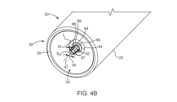
radially inward
direction as the piston 19 is advanced from the proximal end 30 to the distal
end 28 and such
that the outer surface of the sidewall 32 at the folding region 35 is unfolded
in a radially
outward direction as the piston 19 is retracted from the distal end 28 toward
the proximal end
30. Upon pressurization of the rolling diaphragm syringe 20 by distal movement
of the piston
19, the fluid pressure within the rolling diaphragm syringe causes the
sidewall 32 to expand
radially outward. This effect is enhanced by the relative thinness of the
syringe sidewall 32
compared to conventional syringes. As the syringe sidewall 32 expands radially
outward, it
contacts the interior surface of the pressure jacket 16, which limits further
expansion of the
syringe sidewall 32.
[00102] FIGS. 3A-3B show the rolling diaphragm syringe 20 in combination with
one
embodiment of a engagement mechanism 48 of the piston 19 in accordance with
some
embodiments of the present disclosure. The components of the rolling diaphragm
syringe 20
shown in FIGS. 3A-3B are substantially similar to the components of the
rolling diaphragm
syringe 20 described herein with reference to FIGS. 2A-2B. The engagement
portion 46 of
the rolling diaphragm syringe 20 is configured for interacting with one or
more engagement
pins or surfaces 86 of the engagement mechanism 48 that reversibly move
radially inward
and outward to engage and disengage, respectively, the engagement portion 46
of the rolling
diaphragm syringe 20. In various examples, the inward/outward movement of
engagement
elements or surfaces 56 may be effected by a proximal/distal movement of the
piston 19 or
may be moved inward/outward by one or more motive forces provided by the fluid
injector
10. The engagement elements or surfaces 56 may be moved radially
inward/outward via
linear movement, arcuate movement, or a combination of linear and arcuate
movement.
[00103] In various aspects, movement of the piston 19 in the proximal
direction may cause
the engagement elements or surfaces 56 to move inwards and contact the
engagement portion
46 of the syringe 30 such that the end wall 34 of the rolling diaphragm
syringe 20 may be
17
CA 03102226 2020-12-01
WO 2019/236367
PCT/US2019/034556
moved proximally with the proximal movement of the piston 19. Conversely,
movement of
the piston 19 in a distal direction may cause the engagement elements or
surfaces 56 to be
released from contacting the engagement portion 46 of the rolling diaphragm
syringe 20 such
that the rolling diaphragm syringe 20 may be removed from the pressure jacket
16 and the
injector 10. In various examples, the piston 19 may be movable by a motor
drive, a solenoid
drive, or it may be an electro-active polymer. Syringe engagement mechanism 48
may be any
of the syringe engagement mechanisms described in International Application
Publication
No. WO 2018/075386, the disclosure of which is incorporated herein by
reference.
[00104] With continued reference to FIGS. 3A-3B, according to certain
embodiments the
piston 19 may have an outer piston sleeve 50 and an abutment section 52
movably received
within the outer piston sleeve 50 at a distal end thereof The outer piston
sleeve 50 has a
substantially cylindrical structure with an open proximal end and an open
distal end. The
abutment section 52 has an outer engagement surface 57 at its distal end for
engaging at least
a portion of the proximal end 30 of the rolling diaphragm syringe 20 when the
piston 19 is
advanced distally to engage with the rolling diaphragm syringe 20. In some
embodiments, the
abutment section 52 of the piston 19 may contact at least a portion of the
proximal end 30 of
the rolling diaphragm syringe 20, such as the end wall 34. The outer
engagement surface 57
may be shaped to correspond to the shape of the end wall 34 such that the
outer engagement
surface 57 is in surface-to-surface contact with at least a portion of the end
wall 34 when
engaged with the rolling diaphragm syringe 20. The outer engagement surface 57
and outer
piston sleeve 50 define a surface over which the sidewall 32 of the rolling
diaphragm syringe
20 may roll over during a fluid filling or a fluid delivery process due to
proximal or distal
movement of the piston 19, respectively.
[00105] An opening 55 is formed in a central portion of the abutment section
52. The
opening 55 is configured to receive at least a portion of the engagement
portion 46 of the
rolling diaphragm syringe 20 when the abutment section 52 substantially
contacts the end
wall 34 of the syringe 20. In certain embodiments, an inner diameter of the
opening 55 is
larger than an outer diameter of the widest portion of the engagement portion
46 to allow free
insertion of the engagement portion 46 into the opening 55 during distal
movement of the
piston 19 toward the end wall 34 of the rolling diaphragm syringe 20 or
proximal movement
of the end wall 34 of the rolling diaphragm syringe 20 toward the piston 19,
for example
during insertion of the rolling diaphragm syringe 20 into the pressure jacket
16, as well as
free removal of the engagement portion 46 from the opening 55 during removal
of the rolling
diaphragm syringe 20.
18
CA 03102226 2020-12-01
WO 2019/236367
PCT/US2019/034556
[00106] In some embodiments, the abutment section 52 may be axially movable
relative to
the outer piston sleeve 50, which is held in a substantially fixed position,
for example due to
friction between the outer piston sleeve 50 and the piston 19. The abutment
section 52 is
movable or slidable in an axial direction relative to the outer piston sleeve
50 to control the
state or position of one or more engagement elements 56, as described herein.
The movement
of the abutment section 52 relative to the outer piston sleeve 50 is
configured to allow
engagement or disengagement of the one or more engagement elements 56 with the
engagement portion 46 of the rolling diaphragm syringe 20, as described
herein.
[00107] With continued reference to FIGS. 3A-3B, the syringe engagement
mechanism
48 includes one or more engagement elements 56 configured for contacting the
engagement
portion 46 of the rolling diaphragm syringe 20 during at least a proximal
movement of the
piston 19 to facilitate unrolling of the rolling diaphragm syringe 20. The one
or more
engagement elements 56 and optionally a plurality of engagement elements 56
are spaced
apart radially relative to the engagement portion 46 of the rolling diaphragm
syringe 20 when
the rolling diaphragm syringe 20 is inserted into the injector 10. In some
embodiments, a
single engagement element 56 may be configured to contact the engagement
portion 46 of the
rolling diaphragm syringe 20. In other embodiments, at least one pair of
engagement
elements 56 may be positioned opposite one another with the engagement portion
46 of the
rolling diaphragm syringe 20 disposed therebetween. The engagement elements 56
may be
spaced apart at equal or unequal angular intervals from one another.
[00108] The engagement elements 56 may be movable between a first position
(FIG. 3A),
where the engagement elements 56 do not contact the engagement portion 46 of
the rolling
diaphragm syringe 20, and a second position (FIG. 3B), wherein the engagement
elements 56
contact the outer surface of the engagement portion 46 of the rolling
diaphragm syringe 20.
The engagement elements 56 may be movable in a radially inward/outward
direction linearly
or non-linearly, such as in an arcuate movement, for example due to pivoting
about a pivot
point 83. In some embodiments, the engagement elements 56 may have a sharpened
edge or
pointed terminal ends 86 for embedding at least a portion of the engagement
elements 56 into
the material of the engagement portion 46 of the rolling diaphragm syringe 20
when the
engagement elements 56 are positioned in the second position (FIG. 3B). In the
second
position, the edge of the terminal ends 86 of the engagement elements 56 may
dig into and
become at least partially embedded into the material of the engagement portion
46.
[00109] According to various examples, the inward/outward movement of the
engagement
elements 56 in FIGS. 3A-3B and depth of engagement of the engagement element
56 and the
19
CA 03102226 2020-12-01
WO 2019/236367
PCT/US2019/034556
engagement portion 46 may at least in part be dependent on proximal/distal
movement of the
piston 19. For example, the engagement element may be angled so that the
sharpened edge or
pointed end are directed at a proximal angle such that during initial movement
of the piston
19 in the proximal direction, the engagement elements 56 may be advanced
radially inward to
an initial contact position where the engagement elements 56 contact the outer
surface of the
engagement portion 46 of the rolling diaphragm syringe 20. With continued
proximal
movement of the piston 19, the angled edge or point of the engagement elements
56 may
continue to move in a radially inward direction from the initial contact
position such that the
engagement elements 56 and pointed edge/terminal ends 86 dig further into or
become
embedded within the material of the engagement portion 46 of the rolling
diaphragm syringe
20 by the proximal movement of the piston 19 to increase the holding force on
the
engagement portion 46 and therefore the end wall 34 of the rolling diaphragm
syringe 20.
The engagement elements 56 may move to a final contact position having a
maximum radial
displacement from the initial contact position at a final proximal position of
the piston 19. In
some embodiments, radial movement of the engagement elements 56 may further be
a
function of proximal movement of the piston 19 in a direction of arrow B shown
in FIG. 3B.
That is, as the piston 19 is moved further in the proximal direction, the
force of the "bite" or
radially inward force between the engagement elements 56 and the edge/pointed
terminal
ends 86 with the engagement portion 46 increases so that any proximal slipping
of the
pointed terminal ends 86 through the material of the engagement portion 46 is
counteracted.
Further, as the edge/pointed terminal ends 86 dig into the material of the
engagement portion
46 a portion of the material of the engagement portion 46 may be forced
radially outward
forming a berm 98 of surface material proximal to the edge/pointed terminal
ends 86 of the
engagement elements 56 that increases the holding force of the engagement
elements 56 with
the engagement portion 46. According to the various embodiments described
herein, the
plurality of grooves 94 in the surface of the engagement portion 46 may
increase the depth
that the engagement elements 56 embeds into the engagement portion 46 and/or
the height of
berm 98, thereby increasing the "bite" and retaining force between the
engagement elements
56 and the engagement portion 46.
[00110] In other embodiments, the inward/outward movement of the engagement
elements
56 may occur independently of the proximal/distal movement of the piston 19
due to
operation of a drive mechanism 88. The drive mechanism 88 may be configured
for
controlling the movement of the engagement elements 56 between a first,
disengaged
position (FIG. 3A) and a second, engaged position (FIG. 3B). The drive
mechanism 88 may
CA 03102226 2020-12-01
WO 2019/236367
PCT/US2019/034556
be associated with at least a portion of the piston 19. In various examples,
the drive
mechanism 88 may be mechanically, electrically, pneumatically, and/or
hydraulically
operated. For example, the drive mechanism 88 may have an electric or
electromechanical
mechanism, such as a linear or rotary electric motor, or a solenoid. In other
examples, the
drive mechanism 88 may be activated/deactivated by an electromagnetic
mechanism, an
electroactive polymer mechanism, or a shape-memory alloy-based mechanism (such
as
nitinol wire). Various combinations of these mechanisms are also contemplated
at being
within the scope of the present disclosure. In some embodiments, the drive
mechanism 88
may be selectively energized, such as during proximal or distal movement of
the piston 19. In
other examples, the drive mechanism 88 may be constantly energized, regardless
of whether
the piston 19 is stationary, or moving in the proximal or distal direction.
[00111] With reference to FIGS. 4A-4C, rolling diaphragm syringes 20 with
various
examples of the engagement portion 46 are shown. In each example shown in
FIGS. 4A-4C,
the engagement portion 46 is configured for interacting with an engagement
mechanism 48
on the piston 19 of the fluid injector 10, as described herein. Each
engagement portion 46
extends in the proximal direction along the central axis 47 from the central
portion 44 of the
end wall 34. The engagement portion 46 is monolithically formed with the
rolling diaphragm
syringe 20 such that a base 90 of the engagement portion 46 is integrally
formed with the end
wall 34 of the syringe 19. In some embodiments, the base 90 of the engagement
portion 46
may be non-removably attached to the central portion 44 of the end wall 34,
such as by
welding, adhesion, or clip attachment, or other fastening mechanism.
[00112] With continued reference to FIGS. 4A-4C, the engagement portion 46 has
a body
92 protruding proximally from the base 90. In some embodiments, such as shown
in FIG.
4C, an outer diameter Do of the body 92 may be substantially uniform
throughout a
longitudinal length of the body 92. In other embodiments, such as shown in
FIGS. 4A-4B,
the outer diameter Do of the body 92 may be non-uniform. For example, the
diameter Do of
the body 92 may decrease in a proximal direction extending away from the base
90. In other
embodiments, the outer diameter Do of the body 92 may increase in the proximal
direction
extending away from the base 90. In further examples, the diameter Do of the
body 92 may
increase over a first portion of the longitudinal length of the body 92 in a
proximal direction
extending away from the base 90 and decrease over a second portion of the
longitudinal
length of the body 92, or vice versa. Changes in the outer diameter Do of the
engagement
portion 46 over the longitudinal length of the body 92 may have an impact of
the holding
21
CA 03102226 2020-12-01
WO 2019/236367
PCT/US2019/034556
force between the engagement elements 56 of the piston 19 and the engagement
portion 46 of
the rolling diaphragm syringe 20.
[00113] With continued reference to FIGS. 4A-4C, the body 92 of the engagement
portion
46 has one or more grooves 94 recessed radially inward relative to an outer
surface 96 of the
body 92. In this manner, the body 96 has a core 97 with one or more splines 99
extending
radially outward and defined between adjacent grooves 94. The one or more
grooves 94 may
be formed during manufacture of the rolling diaphragm syringe 20, such as
during the
molding operation to form the rolling diaphragm syringe 20. For example, in
one
embodiment, the one or more grooves 94 may be formed during an injection
molding
operation to form a preform that may be ultimately blow-molded to form the
rolling
diaphragm syringe 20. In another embodiment, the one or more grooves 94 may be
formed
during the blow-molding process to form the rolling diaphragm syringe 20
where, as the
engagement portion 46 on the preform moves into its final position in the blow-
mold, the
material of the engagement portion 46 is heated to the glass transition
temperature and the
one or more grooves 94 are press molded into the body 92 of the engagement
portion 46. In
some embodiments, the one or more grooves 94 may be formed on the body 92 in a
separate
manufacturing operation after the rolling diaphragm syringe 20 is formed. For
example, the
one or more grooves 94 may be cut into the outer surface 96 of the body 92
after the rolling
diaphragm syringe 20 is molded. In another embodiment, the one or more grooves
94 may be
molded into the engagement portion 46 during a rolling process, as described
in PCT
International Application No. PCT/US2019/018404, the disclosure of which is
incorporated
by reference, where before, during, or after the rolling process, the material
of the
engagement portion 46 is heated to the glass transition temperature and the
one or more
grooves 94 are press molded into the body 92 of the engagement portion 46. In
certain
embodiments, the one or more grooves 94 may be identical to each other. In
some
embodiments, at least one of the one or more grooves 94 may be different from
the other
grooves 94. While FIGS. 4A-4C show the one or more grooves 94 as having a
substantially
through-shaped form with a base and a pair of sides extending from the base,
other examples
of the one or more grooves 94 may have other geometric shapes, for example a
rounded or
curved base surface.
[00114] The one or more grooves 94 have a length L along at least a portion of
the
longitudinal length of the body 92 in a direction along the central axis 47.
In some
embodiments, the length L may be continuous over at least a portion of the
longitudinal
length of the body 92 in the direction along the central axis 47. In other
embodiments, the one
22
CA 03102226 2020-12-01
WO 2019/236367
PCT/US2019/034556
or more grooves 94 may be discontinuous along the longitudinal length of the
body 92 in the
direction along the central axis 47. The one or more grooves 94 may be spaced
apart at equal
or unequal intervals along the outer surface 96 of the body 92 of the
engagement portion 46
in a direction about the central axis 47. The one or more grooves 94 may have
equal or
unequal widths W measured along the outer surface 96 of the engagement portion
46 in the
direction about the central axis 47. While FIGS. 4A-4C show a plurality of
grooves 94
having equal widths W and/or equal circumferential spacing therebetween, other
examples of
the engagement portion 46 may have grooves with unequal widths W and/or
unequal
circumferential spacing. While FIGS. 4A-4C show a plurality of grooves 94
having
extending parallel to the central axis 47, in other embodiments, the one or
more grooves may
be formed around the circumference of the body 92. According to another
embodiment, the
one or more grooves may be formed in a spiral arrangement around the body 92
along the
length of the body. Other embodiments may include combinations of these groove
configurations, such as a cross-hatched pattern over the length of the body
92. In still other
embodiments, a first portion of the body 92 may include one or more
circumferential grooves
a second portion may include one or more longitudinal grooves. Further, in
various
embodiments, the grooves may be along a portion of the length of the body 92,
such that a
portion of the engagement portion 46 does not have any surface grooves.
[00115] With continued reference to FIGS. 4A-4C, the one or more grooves 94
have a
depth D in a radially inward direction from the outer surface 96 of the body
92. In some
embodiments, the depth D of the one or more grooves may be in the range of
0.003 to 0.080
inches, such as 0.020 to 0.080 inches. The depth D may be uniform along the
entire length L
of each of the one or more grooves 94, such as shown in FIGS. 4A-4B. In some
embodiments, the depth D may be non-uniform along at least a portion of the
length L of at
least one of the one or more grooves 94. For example, with reference to FIG.
4C, the depth D
may increase along the length L of the one or more grooves 94 in the proximal
direction of
the body 92 extending from the base 90. In such examples, the core 97 may be
tapered, such
that its diameter increases or decreases in a proximal direction of the body
92, while an outer
diameter of the body 92 may be uniform. Alternatively, the core 97 may have a
uniform
diameter, while an outer diameter of the body 92 may increase or decrease in a
proximal
direction of the body 92.
[00116] In some embodiments, one or more radially spaced apart grooves 94 may
be
combined with one or more axially spaced grooves such that the engagement
portion 46 of
the rolling diaphragm syringe 20 has a plurality of "dots" defined by the
radial and axial
23
CA 03102226 2020-12-01
WO 2019/236367
PCT/US2019/034556
grooves. For example, the one or more radial grooves may be similar to any of
the grooves 94
described herein with reference to FIGS. 4A-4C while the one or more axial
grooves may be
oriented at an angle relative to the radial grooves, such as substantially
perpendicular to the
radial grooves, to define a pattern of "dots" or other shapes on the outer
surface 96 of the
body 92. In some embodiments, the "dots" may have a rectangular shape, a
circular shape, or
any other geometric shape.
[00117] With reference to FIG. 6A, the body 92 of the engagement portion 46
may have a
first diameter D1 at its distal end that is connected to the end wall 34 of
the rolling diaphragm
syringe 20. The diameter of the body 92 may decrease from the first diameter
D1 at the distal
end to a second diameter D2 at an intermediate portion 63 of the body 92 and
then increases
from the second diameter D2 to a third diameter D3 at the proximal end of the
body 92. In
this manner, the body 92 may have a narrowed diameter at the intermediate
portion 63
between the proximal and distal ends. The first diameter D1 and the third
diameter D3 are
both larger than the second diameter D3. The first diameter D1 and the third
diameter D3
may be equal to each other, or one of the two may be larger than the other.
[00118] With reference to FIG. 6B, body 92 of the engagement portion 46 may
have a
widened portion 65 at a proximal end 67. The widened portion 65 may extend
radially
outward relative to an outer surface of the body 92 such that a diameter of
the widened
portion 65 is larger than a diameter of the body 92 distal of the widened
portion 65. In some
embodiments, the one or more grooves 94 (shown in FIGS. 4A-4C) may be provided
on at
least one of the body 92 and the widened portion 65. In the embodiments
illustrated in FIGS.
6A and 6B, the increased diameter of the proximal end of the body 92 may allow
better
gripping or "bite" between the engagement elements 56 and the engagement
portion 46.
[00119] Without intending to be bound by any theory, it has been found that
the one or
more grooves 94 contributes to a more consistent physical contact force
between the
engagement portion 46 of the rolling diaphragm syringe 20 and the engagement
elements 56
of the piston 19 during proximal movement of the piston 19. With reference to
FIGS. 5A-5B,
the engagement elements 56 of the engagement mechanism 48 are shown in the
second
position, wherein the engagement elements 56 directly contact the outer
surface of the body
92 of the engagement portion 46. In particular, the edge or pointed terminal
end 86 of each
engagement element 56 physically contacts the outer surface 96 of the body 92
and is
embedded or digs into the material of the engagement portion 46 of the rolling
diaphragm
syringe 20. In this manner, the engagement elements 56 are directly connected
to the
engagement portion 46 of the rolling diaphragm syringe 20 to allow the
proximal end wall 34
24
CA 03102226 2020-12-01
WO 2019/236367
PCT/US2019/034556
rolling diaphragm syringe 20 to be pulled back or unrolled with a proximal
movement of the
piston 19. This embedding or digging action of the edge or pointed terminal
end 86 of each
engagement element 56 may be increased during proximal movement of the piston
19,
particularly if the edge or pointed terminal end 86 is angled in a proximal
direction relative to
the engagement portion 46 so that proximal movement burrows the edge or
pointed terminal
end 86 of each engagement element 56 further into the engagement portion 46.
The grooves
or splines of the present disclosure reduces the amount of surface material on
the body 92
into which the engagement elements 56 must burrow, allowing the engagement
elements 56
to burrow further into the material of the body 92.
[00120] With reference to FIGS. 5C-5E, contact between the edge or pointed
terminal end
86 of each engagement element 56 with the outer surface 96 of the body 92
deforms at least a
portion of the body 92 and the plurality of grooves 94. For example, as shown
in FIG. 5E,
contact between the edge or pointed terminal end 86 of each engagement element
56 with the
outer surface 96 of the body 92 may deform the body 92 by drawing excess
material
proximally to form the berm 98 proximal to a proximal edge 102 of the edge or
pointed
terminal end 86. The berm 98 may prevent skipping or dragging of the
engagement elements
56 along the longitudinal length of the body 92 of the engagement portion 46
during proximal
movement of the piston 19. The deformation of the engagement portion 46 of the
rolling
diaphragm syringe 20 due to contact with the engagement elements 56 allows the
engagement elements 56 to grip the engagement portion 46. Incorporation of the
grooves or
splines of the present disclosure into the surface of the engagement portion
46 allows the
engagement elements 56 to more readily dig into the material of the outer
surface 96 of the
body 92 of the engagement portion 46 thereby increasing the grip of the
engagement
elements 56 on the engagement portion 46. In addition to the deformation of
the outer surface
96 of the body 92 of the engagement portion 46, the one or more grooves 94 may
be
deformed due to engagement between the edge or pointed terminal end 86 of each
engagement element 56 with the outer surface 96 of the body 92. For example,
the base
surface and/or the pair of sides may be deformed with the deformation of the
outer surface 96
of the body 92. In embodiments where the body 92 has a widened portion 65 at
its proximal
end, such as shown in FIG. 6B, the widened portion 65 may provide a stop
surface that
prevents sliding of the engagement elements 56 in an axial direction relative
to the body 92.
According to certain embodiments having widened portion 65, the one or more
grooves 94
may be on both the body 92 of engagement portion 46 and on the widened portion
65. In
CA 03102226 2020-12-01
WO 2019/236367
PCT/US2019/034556
other embodiments having widened portion 65, the one or more grooves 94 may be
only on
the body 92 of engagement portion 46 and not on the widened portion 65.
[00121] In some embodiments, the outer surface 96 of the body 92 including the
one or
more grooves 94 may be plastically deformed such that its shape is permanently
changed
after the engagement elements 56 are disengaged from the outer surface 96 of
the body 92. In
other embodiments, the outer surface 96 of the body 92 including the one or
more grooves 94
may be elastically deformed during contact with the engagement elements 56.
According to
certain embodiments, after disengaging the engagement elements 56 from the
engagement
portion 46, the outer surface 96 of the body 92 may revert to its original
shape prior to
engagement with the engagement elements 56. In other embodiments, after
disengaging the
engagement elements 56 from the engagement portion 46, the outer surface 96 of
the body 92
may remain deformed by the contact with the engagement elements 56.
[00122] While examples of a fluid delivery system and a syringe for use
therefor were
provided in the foregoing description, those skilled in the art may make
modifications and
alterations to these examples without departing from the scope and spirit of
the disclosure.
Accordingly, the foregoing description is intended to be illustrative rather
than restrictive.
The disclosure described hereinabove is defined by the appended claims, and
all changes to
the disclosure that fall within the meaning and the range of equivalency of
the claims are to
be embraced within their scope.
26