Note: Descriptions are shown in the official language in which they were submitted.
PATENT APPLICATION
Frame for a Floor Drain
Priority Claim
Priority is claimed of and to German Patent Application Serial No. DE 20 2019
107 083.8, filed December 18, 2019.
BACKGROUND OF THE INVENTION
Field of the Invention
The present invention relates to a frame for a floor drain which can be used,
in
particular, in the construction of flush-with-floor showers.
SUMMARY OF THE INVENTION
It is an object of the present invention to improve the installability of the
floor drain
and to improve the cleaning of the areas of the floor drain that are
accessible after
installation.
In order to achieve this object, the present invention provides a frame made
of
sheet metal and designed to be inserted into a channel body of a floor drain,
said channel
body forming an oufflow channel and having an oufflow opening, said frame
comprising
at least substantially vertically extending side walls arranged in the form of
a frame and
which together form a receiving opening, and an at least substantially
horizontally
extending frame flange that surrounds the receiving opening in a frame-like
manner and
adjoins the upper edges of the side walls, wherein projections projecting into
the receiving
opening are provided on opposite side walls and form a receiving matrix or
receiving
means or receiving framework for a cover to be inserted into the frame from
above,
characterized in that the projections are provided in the form of
indentations. A significant
advantage of the frame according to the invention is that in the production of
the
1
Date Recue/Date Received 2020-12-10
projections in the form of indentations, no recesses, openings or through-
holes are made
below the projections in the side walls. Accordingly, the step of covering the
recesses with
adhesive tape is dispensed with, thereby facilitating assembly. Moreover, the
frame can
be cleaned much more easily in the region of the projections, as water or
other liquid will
not flow through any openings in the side walls. Furthermore, if there are
indentations,
the frame need not be deburred in the region of the projections in order to
prevent injuries,
whereby the manufacture of the frame is simplified and the risk of injury is
reduced.
The upwardly facing surfaces of the projections preferably extend at least
substantially horizontally in order to provide a good bearing surface for the
cover.
The projections are advantageously of elongate design in order to make the
bearing surfaces large.
The lower edges of the side walls preferably extend in a straight line, i.e.
are not
interrupted by recesses.
Furthermore, the present invention provides a floor drain having a channel
body
forming an outflow channel and having an outflow opening; a frame according to
one of
the preceding claims which can be inserted into the channel body from above;
and a
cover which can be inserted into the frame from above, wherein the dimensions
of the
frame and the cover are matched to each other such that the projections of the
frame
receive the cover inserted into the frame.
Further features and advantages of the present invention will become apparent
from the following description of a frame according to an embodiment of the
present
invention with reference to the accompanying drawings. These show
BRIEF DESCRIPTION OF THE DRAWINGS
Figure 1 is a schematic perspective view of a floor drain as known in the
prior art;
2
Date Recue/Date Received 2020-12-10
Figure 2 is a cross-sectional view showing the floor drain shown in Figure 1
in the
installed state;
Figure 3 is a plan view of a frame according to an embodiment of the present
invention;
Figure 4 is a side view of the frame shown in Figure 3;
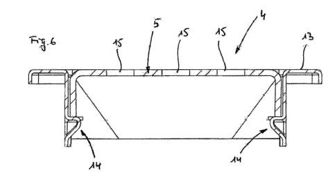
Figure 5 is a sectional view along the line V-V in Figure 4; and
Figure 6 is a sectional view analogous to Figure 5, wherein a cover has been
inserted into the frame from above.
DETAILED DESCRIPTION
Reference will now be made to the exemplary embodiments illustrated in the
drawings, and specific language will be used herein to describe the same. It
will
nevertheless be understood that no limitation of the scope of the invention is
thereby
intended. Alterations and further modifications of the inventive features
illustrated
herein, and additional applications of the principles of the inventions as
illustrated
herein, which would occur to one skilled in the relevant art and having
possession of
this disclosure, are to be considered within the scope of the invention.
Definitions
As used herein, the singular forms "a" and "the" can include plural referents
unless the context clearly dictates otherwise. Thus, for example, reference to
"a
projection" can include one or more of such projections, if the context
dictates.
As used herein, the term "substantially" refers to the complete or nearly
complete extent or degree of an action, characteristic, property, state,
structure, item, or
result. As an arbitrary example, an object that is "substantially" enclosed is
an article
that is either completely enclosed or nearly completely enclosed. The exact
allowable
degree of deviation from absolute completeness may in some cases depend upon
the
3
Date Recue/Date Received 2020-12-10
specific context. However, generally speaking the nearness of completion will
be so as
to have the same overall result as if absolute and total completion were
obtained. The
use of "substantially" is equally applicable when used in a negative
connotation to refer
to the complete or near complete lack of an action, characteristic, property,
state,
structure, item, or result. As another arbitrary example, a composition that
is
"substantially free of' an ingredient or element may still actually contain
such item so
long as there is no measurable effect as a result thereof.
As used herein, the term "about" is used to provide flexibility to a numerical
range
endpoint by providing that a given value may be "a little above" or "a little
below" the
endpoint.
Relative directional terms can sometimes be used herein to describe and claim
various components of the present invention. Such terms include, without
limitation,
"upward," "downward," "horizontal," "vertical," etc. These terms are generally
not
intended to be limiting, but are used to most clearly describe and claim the
various
features of the invention. Where such terms must carry some limitation, they
are intended
to be limited to usage commonly known and understood by those of ordinary
skill in the
art in the context of this disclosure. Generally, directional terms used in
this application,
such as top" or 'bottom" refer to the installed state. The formulations
'Substantially
vertical" and "substantially horizontal" are to be construed such that the
main extension
direction is vertical and horizontal, respectively.
As used herein, a plurality of items, structural elements, compositional
elements,
and/or materials may be presented in a common list for convenience. However,
these
lists should be construed as though each member of the list is individually
identified as a
separate and unique member. Thus, no individual member of such list should be
construed as a de facto equivalent of any other member of the same list solely
based on
their presentation in a common group without indications to the contrary.
Numerical data may be expressed or presented herein in a range format. It is
to
be understood that such a range format is used merely for convenience and
brevity and
thus should be interpreted flexibly to include not only the numerical values
explicitly
recited as the limits of the range, but also to include all the individual
numerical values
4
Date Recue/Date Received 2020-12-10
or sub-ranges encompassed within that range as if each numerical value and sub-
range
is explicitly recited. As an illustration, a numerical range of "about 1 to
about 5" should
be interpreted to include not only the explicitly recited values of about 1 to
about 5, but
also include individual values and sub-ranges within the indicated range.
Thus,
included in this numerical range are individual values such as 2, 3, and 4 and
sub-
ranges such as from 1-3, from 2-4, and from 3-5, etc., as well as 1,2, 3,4,
and 5,
individually.
This same principle applies to ranges reciting only one numerical value as a
minimum or a maximum. Furthermore, such an interpretation should apply
regardless
of the breadth of the range or the characteristics being described.
Invention
The present invention relates to a frame made of sheet metal and designed to
be
inserted into a channel body of a floor drain, said channel body forming an
outflow channel
and having an outflow opening, said frame comprising at least substantially
vertically
extending side walls arranged in the form of a frame and which together form a
receiving
opening, and an at least substantially horizontally extending frame flange
that surrounds
the receiving opening in a frame-like manner and adjoins the upper edges of
the side
walls, wherein projections projecting into the receiving opening are provided
on opposite
side walls and form a receiving means for a cover to be inserted into the
frame from
above.
In the following, identical reference numerals denote functionally identical
components or component regions as in Figures 1 and 2. Furthermore, it is
advised that
directions used in this application, such as "top" or "bottom" refer to the
installed state.
The formulations "substantially vertical" and "substantially horizontal" are
to be construed
such that the main extension direction is vertical and horizontal,
respectively.
Floor drains with frames of the aforementioned type are known in principle in
the
prior art. For example, DE 20 2010 002 763 U1, to the disclosure of which the
present
application makes full reference, describes the floor drain 1 shown
schematically in
5
Date Recue/Date Received 2020-12-10
Figures 1 and 2, wherein Figure 1 shows the basic structure and Figure 2 shows
the
installation situation of the floor drain. The floor drain 1 is used primarily
in the construction
of flush-with-floor showers. It comprises a base body 2, a channel body 3, a
frame 4, a
cover 5 and two identical spacers 6 used in the assembly of the floor drain 1.
The base
body 2 is an elongated and substantially rectangular block made of foamed
plastic, such
as, for example, expanded polystyrene. The base body 2 comprises a
longitudinally
extending, groove-like and upwardly open recess 7 which serves for receiving a
waste
pipe, not shown in greater detail, and is formed in the upper region for the
substantially
form-fitting accommodation of the channel body 3. The channel body 3 is made
of sheet
metal, for example aluminum or stainless steel sheet. Alternatively, it can
also be made
of plastic. It forms an outflow channel 8 which is provided with an oufflow
opening 9 to
which the waste pipe to be received by the base body can be connected. The
outflow
channel 8 is enclosed by an outflow channel flange 10, the underside of which
rests on
the upper side of the base body 2 in the assembled state of the floor drain 1.
The frame
4, made of sheet metal such as aluminum or stainless steel sheet, has
substantially
vertically extending side walls 11 arranged in a frame configuration which
together form
a receiving opening 12. Adjoining the upper edges of the side walls 11 is a
substantially
horizontally extending frame flange 13 which encloses the receiving opening 12
in a
frame-like manner and is bent downwards at the free end. Projections 14
projecting into
the receiving opening 12 are provided on opposite side walls 11, in the
present case on
the side walls 11 extending in the longitudinal direction, which projections
form a
receptacle for the cover 5 to be inserted into the frame 4 from above. The
projections 14
are in each case a side wall region positioned between two perpendicular cuts
into a side
wall 11 and bent upward by 90 . The cover 5 takes the form of a substantially
U-shaped
metal profile, which can likewise be made of aluminum or stainless steel
sheet. On the
upper side, the cover 5 is provided with a plurality of through-holes 15 for
draining water
into the channel body 3. In principle, such through-holes 15 can also be
dispensed with.
In this case, the cover 5 would have to be made somewhat narrower and be
laterally
distanced from the side walls 11 of the frame 4 by means of spacers, so that
lateral
drainage slots are created through which the water to be discharged can pass
in the
6
Date Recue/Date Received 2020-12-10
direction of the channel body 3. The spacers 6 each have a rectangular plate
element 16
with two threaded holes 17 through which an adjusting screw 18 extends in each
case.
For the installation of the floor drain 1, as shown in Figure 2, in a first
step the base
body 2 with the channel body 3 accommodated therein and connected to a waste
pipe is
set down on a substrate 19. A sloped board, not shown in detail, is then
placed on the
base body 2 and forms a slope in the direction of the floor drain 1. Instead
of a sloped
board, floor screed or the like can also be used. A circumferential sealing
collar 20 is then
glued to the upper side of the outflow channel flange 10 and projects
laterally outwardly
beyond the outflow channel flange 10 and covers the surrounding area of the
sloped
board. In a further step, the outer sides of the longitudinally extending side
walls 11 of the
frame 4 are sealed with adhesive tape to seal off the recesses provided below
the
projections 14 in the corresponding side walls, whereupon the frame 4 is
arranged on the
channel body 3 in such a way that its side walls 11 are partially inserted
into the outflow
channel 8 of the channel body 3. The two spacers 6 are here positioned at a
distance
from each other in such a way that the free ends of their plate elements 16
engage below
corresponding projections 14 of the frame 4. By manipulating the adjusting
screws 18,
which are supported on the bottom of the outflow channel 8 of the channel body
3, the
distance between the channel body 3 and the frame 4 is then adjusted to the
desired
amount in order to align the upper side of the frame flange 13 flush with the
upper side of
the floor covering that is to be installed. In a further step, the sealing
collar 20 is fixed to
the sloped board, in the present case using thin-bed mortar 21 which is then
also used
for laying the floor covering, more specifically, tiles 22. During the course
of tiling, the
cavity between the outflow channel flange 10 and the frame flange 13 is
filled. The
previously arranged adhesive tape prevents thin-bed mortar 21 from penetrating
through
the frame 4 into the channel body 3. Furthermore, the downwardly bent end of
the frame
flange 13 is embedded in the thin-bed mortar 21. After the thin-bed mortar 21
has
hardened to the point where it can support weight, the adjusting screws 18 of
the spacers
6 are loosened, whereupon the plate elements 16 of the spacers 6 are removed
through
the receiving opening 12 of the frame 4. The adhesive tape is then removed. In
a final
7
Date Recue/Date Received 2020-12-10
step, the cover 5 is inserted into the frame 4 from above in such a way that
it rests on the
projections 14 of the frame 4.
The frame 4 shown in Figures 2 to 6 is made of sheet metal, such as aluminum
or
stainless steel sheet. It has at least substantially vertically extending side
walls 11
arranged in a frame configuration which together form a receiving opening 12.
Adjoining
the upper edges of the side walls 11 is a frame flange 13 which extends at
least
substantially horizontally and surrounds the receiving opening 12 in a frame-
like manner
and is bent downwards at the free end. Projections 14 protruding into the
receiving
opening 12 are provided on opposite side walls 11, in the present case on the
side walls
11 extending in the longitudinal direction L, and form a receptacle for a
cover 5 to be
inserted into the frame 4 from above, as shown in Fig. 6.
The projections 14 are in the embodiment shown indentations which are produced
in the present case by applying external pressure to the side walls 11 with an
embossing
tool. The upwardly facing surfaces 14a of the projections 14 extend at least
substantially
horizontally. A plurality of the upwardly facing surfaces 14a of the
projections collectively
form a receiving means for receiving The downwardly facing surfaces 14b of the
projections 14 point obliquely downwards and away from the associated vertical
side wall
11. The downward facing surfaces 14b and the associated side walls 11
preferably
enclose an angle a of 135 10 , which facilitates the cleaning of the frame 4
in the region
of the projections 14. The projections thus create receiving cavities that can
receive
mortar therein during installation of the frame. The corners of the
projections 14 are
rounded, which is likewise conducive to simple cleaning. The cover 5 may
correspond to
the cover 5 previously described with reference to Figures 1 and 2.
The frame 4 shown in Figures 3 to 6 is designed to be inserted into a channel
body
3 of a floor drain 1 which forms an outflow channel 8 and has an outflow
opening 9. For
example, the frame 4 can thus replace the frame 4 shown in Figures 1 and 2. A
significant
advantage of the frame 4 according to the invention as compared with the frame
4
described with reference to Figures 1 and 2 is that the projections 14 are
produced in the
form of indentations: a such, no recesses or openings or through-holes are
produced
8
Date Recue/Date Received 2020-12-10
below the projections 14. Accordingly, the step of covering the recesses with
adhesive
tape is dispensed with, thereby facilitating assembly. In addition, the
projections 14
designed as indentations can receive thin-bed mortar on their rear side during
installation,
whereby load transfer from the frame is improved. In addition, the frame 4 can
be cleaned
much more easily from the inside in the region of the projections 14.
Furthermore, if there
are indentations, the frame 4 need not be deburred in the region of the
projections 14 in
order to prevent injuries. In the present case, the risk of injury is reduced
as no such
burrs are created during manufacture.
While the manner in which the projections 14 are formed in the side walls 11
can
vary, in some embodiments the projections are formed so that no opening or
though-hole
It should be understood that the above-described embodiment of a frame
according to the invention is not to be understood as restricting the scope of
protection.
Indeed, modifications of the embodiment are possible without departing from
the scope
of protection of the present application, which is defined by the appended
claims.
List of reference numbers
1 Floor drain
2 Base body
3 Channel body
4 Frame
5 Cover
6 Spacer
7 Recess
8 Outflow channel
9 Outflow opening
10 Outflow channel flange
11 Side wall
12 Receiving opening
13 Frame flange
14 Projection
15 Through-hole
16 Plate element
17 Threaded hole
18 Adjusting screw
19 Substrate
9
Date Recue/Date Received 2020-12-10
20 Sealing collar
21 Thin-bed mortar
22 Tile
23 Receiving cavity
L Longitudinal direction
Date Recue/Date Received 2020-12-10