Note: Descriptions are shown in the official language in which they were submitted.
CA 03102591 2020-12-03
WO 2019/235939
PCT/NZ2019/050063
INTERFACE ASSEMBLIES FOR RESPIRATORY THERAPY
BACKGROUND
Field
[0001] The present disclosure relates to interface assemblies for respiratory
therapy. In
particular, the present disclosure relates to under-nose interface assemblies
that do not cover
the bridge of the user's nose.
Description of Related Art
[0002] In patients suffering from obstructive sleep apnea (OSA), muscles that
normally keep
the upper airway open relax during slumber to the extent that the airway is
constrained or
completely closed off, a phenomenon often manifesting itself in the form of
snoring. When
this occurs for a period of time, the patient's brain typically recognizes the
threat of hypoxia
and partially wakes the patient in order to open the airway so that normal
breathing may
resume. The patient may be unaware of these waking episodes, which may occur
as many as
several hundred times per session of sleep. This partial awakening may
significantly reduce
the quality of the patient's sleep, over time potentially leading to a variety
of symptoms,
including excessive daytime sleepiness, chronic fatigue, elevated heart rate,
elevated blood
pressure, weight gain, headaches, irritability, depression and anxiety.
[0003] Obstructive sleep apnea is commonly treated with the application of
positive airway
pressure (PAP) therapy. PAP therapy involves delivering a flow of gas to a
patient at a
therapeutic pressure above atmospheric pressure that will reduce the frequency
and/or
duration of apneas, hypopneas, and/or flow limitations. The therapy is often
implemented by
using a positive airway pressure device to deliver a pressurized stream of air
through a
conduit to a patient through a patient interface or mask positioned on the
face of the patient.
[0004] One common type of patient interface assembly used with PAP therapy or
other
respiratory therapies involving the administration of gas includes a seal that
contacts the
bridge of the nose of a user of the interface assembly. The bridge of the nose
is sensitive to
pressure applied by the seal of the interface assembly. More recently,
interface assemblies
have become available that do not contact the bridge of the nose. Such
interface assemblies
can be referred to as "under-nose" interface assemblies. A need exists to
provide improved
CA 03102591 2020-12-03
WO 2019/235939 PCT/NZ2019/050063
under-nose interface assemblies with improved comfort and/or sealing
performance, or to
provide the public with a useful choice.
SUMMARY
[0005] The systems, methods and devices described herein have innovative
aspects, no single
one of which is indispensable or solely responsible for their desirable
attributes. Without
limiting the scope of the claims, some of the advantageous features will now
be summarized.
[0006] A preferred embodiment involves a headgear assembly for a full-face
under-nose
respiratory mask. The headgear assembly comprises a strap assembly including a
rear panel,
a crown strap, a pair of opposing upper side straps, and a pair of opposing
lower side straps.
The headgear assembly comprises a flexible headgear connector element. A free
end of each
of the upper straps is coupled to the headgear connector element. The headgear
connector
element is configured to extend laterally across and be removably fastened to
a frame of the
respiratory mask below a tip of a user's nose.
[0007] In some configurations, the pair of upper side straps, the headgear
connector element,
and the crown strap forms a closed loop when the headgear connector element is
removed
from the frame.
[0008] In some configurations, the upper straps are adjustably coupled to the
headgear
connector element, such that a user can adjust the length of the upper straps
when the upper
straps are coupled to the headgear connector element.
[0009] In some configurations, the headgear connector element is configured to
be coupled to
and removed from the frame without removing the upper straps from the headgear
connector
element.
[0010] In some configurations, the headgear connector element comprises one or
more
apertures each configured to receive and removably retain a post on the frame.
[0011] In some configurations, the headgear connector element further
comprises thickened
portions at least partially surrounding each of the apertures.
[0012] In some configurations, the headgear connector element comprises a
flexible material,
such that the headgear connector element is able to conform to a curvature of
the frame when
removably fastened to the frame.
2
CA 03102591 2020-12-03
WO 2019/235939 PCT/NZ2019/050063
[0013] In some configurations, the headgear connector element comprises an
elastomeric
material.
[0014] In some configurations, the headgear connector element comprises a
thermoplastic
elastomer material.
[0015] In some configurations, the headgear connector element has a
substantially upward-
concave shape.
[0016] In some configurations, the headgear connector element comprises a pair
of strap
loops, each configured to retain one of the upper straps.
[0017] A preferred embodiment involves a respiratory mask assembly. The
respiratory mask
assembly comprises a frame, a cushion module carried by the frame, and a
headgear
assembly. The cushion module includes a seal and a housing. The seal comprises
a nasal
portion having a pair of upward extensions that extend upwardly from opposite
sides of a
central sealing surface, and an oral portion. The upward extensions may be
referred to as
paddles. The headgear assembly comprises a strap assembly including a rear
panel, a crown
strap, a pair of opposing upper side straps, and a pair of opposing lower side
straps. The
headgear assembly comprises a flexible headgear connector element. A free end
of each of
the upper straps is coupled to the headgear connector element. The headgear
connector
element is configured to extend laterally across and be removably fastened to
the frame
below the upward extensions of the seal.
[0018] In some configurations, the frame is removably connectable to the
cushion module.
[0019] In some configurations, the pair of upper side straps, the headgear
connector element,
and the crown strap forms a closed loop when the headgear connector element is
removed
from the frame.
[0020] In some configurations, the upper straps are adjustably coupled to the
headgear
connector element, such that a user can adjust the length of the upper straps
when the upper
straps are coupled to the headgear connector element.
[0021] In some configurations, the respiratory mask assembly further comprises
an inlet tube
connected to the frame.
3
CA 03102591 2020-12-03
WO 2019/235939 PCT/NZ2019/050063
[0022] In some configurations, the headgear connector element is configured to
be removably
connected to the frame above the inlet tube.
[0023] In some configurations, the headgear connector element comprises one or
more
apertures each configured to receive and removably retain a post on the frame.
[0024] In some configurations, the post comprises an enlarged head that has a
greater cross-
sectional area than the cross-sectional area of the aperture of the headgear
connector element.
[0025] In some configurations, the headgear connector element comprises a
flexible material,
such that the headgear connector element is able to conform to a curvature of
the frame when
removably connected to the frame.
[0026] A preferred embodiment involves a headgear connector element for
connecting a
headgear assembly to a respiratory mask assembly. The headgear connector
element
comprises an elongate flexible main body having a first end and a second end.
The headgear
connector element comprises a pair of strap loops. A first one of the pair of
strap loops is
attached to the first end and a second one of the pair of strap loops is
attached to the second
end of the main body. Each of the strap loops is configured to adjustably
receive a strap of
the headgear assembly. The headgear connector element comprises at least one
aperture that
extends through the main body of the headgear connector element. The aperture
is configured
to receive and removably retain a post of a frame of the mask assembly. The
main body
further comprises a thickened portion at least partially surrounding the at
least one aperture.
[0027] In some configurations, the thickened portion is integrally formed with
the main body.
[0028] In some configurations, the thickened portion is constructed of the
same material as
the main body.
[0029] In some configurations, the thickened portion is over-moulded to the
main body.
[0030] In some configurations, the strap loops and the main body are
constructed of different
materials.
[0031] In some configurations, the main body is constructed of a thermoplastic
elastomer
material, such as for example silicone.
[0032] In some configurations, the strap loops are constructed of nylon.
4
CA 03102591 2020-12-03
WO 2019/235939 PCT/NZ2019/050063
[0033] In some configurations, each of the strap loops comprise a tab and
wherein the main
body is over-moulded over the tab.
[0034] In some configurations, the strap loops and the main body are attached
by a welded
joint.
[0035] In some configurations, the headgear connector element further
comprises a concave
portion along a central portion of a lower edge of the headgear connector
element.
[0036] In some configurations, the headgear connector element is substantially
flat when the
headgear connector element is not coupled to the mask assembly.
[0037] A preferred embodiment involves a seal for a respiratory mask. The seal
comprises an
oral sealing portion configured to seal around a user's mouth. The seal
comprises a nasal
sealing portion configured to seal on the lower surface of a user's nose and
be fully
positioned below a bridge of the user's nose. The nasal sealing portion
comprises a first and
second upward extensions that extend upwardly from opposite sides of a central
sealing
surface. Each of the first and the second upward extensions has an internal
wall configured to
engage with a lateral side of the user's nose, and an external wall configured
to provide
structure to the nasal sealing portion, the internal and external walls being
joined along an
upper edge of the seal. The external walls comprise a pocket having a wall
thickness that is
less than the surrounding wall thickness.
[0038] In some configurations, the external walls further comprise a thickened
rib extending
along an upper portion of the external wall. The thickened rib is proximate to
but spaced from
the upper edge of the seal. The thickened rib has a wall thickness that is
greater than the
surrounding wall thickness. The thickened rib extends from a rear end of the
external wall
towards the front of the seal.
[0039] In some configurations, the thickened rib narrows at opposed ends.
[0040] In some configurations, the thickened rib has a curved or serpentine
shape along its
length.
[0041] In some configurations, the pocket is at least partially defined by the
thickened rib.
[0042] In some configurations, the pocket is substantially teardrop shaped.
CA 03102591 2020-12-03
WO 2019/235939 PCT/NZ2019/050063
[0043] In some configurations, the pocket is located on an interior surface of
the external
walls.
[0044] In some configurations, the thickened rib is located on an interior
surface of the
external walls.
[0045] In some configurations, the thickened rib has varying thickness along
its length.
[0046] According to an aspect of this disclosure, there is provided a
respiratory mask
assembly comprising
a mask frame and a cushion module, the mask frame comprising a breathing gas
inlet
configured to receive a supply of breathable gas and to deliver the breathable
gas to
the cushion module, the cushion module being configured to form a seal with a
user's
face; and
a bias vent on the mask frame and in communication with the cushion module,
and
configured to allow air to be exhausted from the cushion module through the
bias
vent;
wherein the mask assembly further comprises:
a diffuser comprising diffuser material configured to extend over the bias
vent, the
diffuser material providing a tortuous air path from the bias vent through the
diffuser;
and
a headgear connector element configured to be removably mounted on a front
part of
the mask frame so as to extend laterally across the mask frame to define
opposed
distal ends, each opposed distal end being configured to be connected to
headgear, the
headgear connector element comprising at least one aperture which is aligned
with the
bias vent when the headgear connector element is mounted on the mask frame.
[0047] The diffuser may be positioned between the mask frame and the headgear
connector
element. The diffuser may be positioned on the headgear connector element. The
diffuser
may be positioned on a front surface of the headgear connector element, that
is, a surface of
the headgear connector element that does not face the mask frame. At least a
portion of the
diffuser may be spaced from the bias vent so that the portion of the bias vent
is not in direct
contact with the bias vent. The diffuser may be provided on the headgear
connector element
6
CA 03102591 2020-12-03
WO 2019/235939 PCT/NZ2019/050063
and may be spaced away from the mask frame by the headgear connector element.
The
diffuser may be provided on the mask frame.
[0048] The diffuser may comprise a diffuser frame, configured to be mounted on
the mask
frame, and the diffuser material may be held by the diffuser frame. The
diffuser material may
be held by the diffuser frame so as to be spaced from the bias vent so that
the portion of the
bias vent is not in direct contact with the bias vent. The diffuser frame
and/or the diffuser
material may comprise at least one raised portion and at least one recessed
portion, the raised
portion being configured to space the recessed portion away from the bias
vent. A plurality
of raised portions and/or a plurality of recessed portions may be provided.
[0049] The diffuser may be of substantially the same shape and size as the
bias vent.
[0050] The diffuser may be removably mounted on the mask assembly.
[0051] The diffuser may be removably mounted on the headgear connector
element.
[0052] The diffuser may be removably mounted on the mask frame via a clip on
one of the
diffuser and mask frame which engages the other of the diffuser and the mask
frame.
[0053] The diffuser may be permanently mounted on the mask assembly.
[0054] The headgear connector element may comprise a plurality of apertures.
The plurality
of apertures may be arranged in a U or V shaped vent array symmetrically about
a vertical
centre line of the mask frame, when the mask frame is viewed from the front.
The or each
aperture of the headgear connector element may be located above the breathing
gas inlet
when the headgear connector element is mounted on the mask frame.
[0055] The bias vent may comprise a plurality of vent holes. The plurality of
vent holes may
be arranged in a vent hole array. There may be a plurality of vent hole
arrays. The vent hole
arrays may be arranged symmetrically about a vertical centre line of the mask
frame, when
viewed from the front.
[0056] The headgear connector element may comprise an elongate flexible member
that
couples upper side straps of the headgear to the frame. The headgear connector
element may
extend laterally across the mask frame below a tip of a user's nose, when
coupled to the mask
frame.
7
CA 03102591 2020-12-03
WO 2019/235939 PCT/NZ2019/050063
[0057] The headgear connector element may comprise a central body portion, and
a pair of
opposed laterally extending arms extending from the central body portion, the
arms
terminating in the opposed distal ends for connection to the headgear, the
aperture being
provided in the central body portion. The central body portion may be arcuate
so as extend
downwardly from the arms in a U or V shape. The headgear connector element may
comprise a laterally extending brace element, extending between the laterally
extending arms,
above the central body portion. The laterally extending arms may be inclined
upwardly away
from the central body portion.
[0058] The mask assembly may comprise a locating feature, configured to locate
the
headgear connector element against the mask frame to resist movement of the
headgear
connector element relative to the mask frame. The locating feature may be
configured to
locate the headgear connector element against the mask frame to resist
vertical movement of
the headgear connector element relative to the mask frame in a direction
generally aligned
with a vertical central line of the mask frame when viewed from the front. The
locating
feature may comprise a recess or protrusion on the mask frame, against which
the headgear
connector element abuts or otherwise engages.
[0059] According to another aspect of this disclosure there is provided a
respiratory mask
assembly comprising:
a mask frame and a cushion module, the mask frame comprising a breathing gas
inlet
configured to receive a supply of breathable gas and to deliver the breathable
gas to
the cushion module, the cushion module being configured to form a seal with a
user's
face; and
a bias vent on the mask frame and in communication with the cushion module,
and
configured to allow air to be exhausted from the cushion module through the
bias
vent;
wherein the mask assembly further comprises:
a diffuser comprising a diffuser frame which holds diffuser material
configured to
extend over the bias vent, the diffuser material providing a tortuous air path
from the
bias vent through the diffuser, the diffuser frame being mounted on a front
surface of
the mask frame.
8
CA 03102591 2020-12-03
WO 2019/235939 PCT/NZ2019/050063
[0060] According to a further aspect of this disclosure there is provided a
respiratory mask
assembly comprising
a mask frame and a cushion module, the mask frame comprising a breathing gas
inlet
configured to receive a supply of breathable gas and to deliver the breathable
gas to
the cushion module, the cushion module being configured to form a seal with a
user's
face;
the mask frame being connected to the cushion module via a cushion connector
comprising a gas flow duct extending from the mask frame into the cushion
module
and arranged to deliver breathable gas to the cushion module from the
breathing gas
inlet; and
a bias vent in communication with the cushion module, and configured to allow
air to
be exhausted from the cushion module through the bias vent;
wherein the bias vent is provided on the gas flow duct.
[0061] The mask assembly may comprise a diffuser comprising diffuser material
configured
to extend over the bias vent, the diffuser material providing a tortuous air
path from the bias
vent through the diffuser. The diffuser may be arcuate and configured to
extend around part
of the exterior of the gas flow duct. The diffuser may be configured to be
concentrically
mounted on the gas flow duct. The diffuser may be arranged as a ring of
diffuser material
configured to receive the gas flow duct.
[0062] The bias vent may comprise a plurality of vent holes. The vent holes
may be spaced
around at least a portion of the perimeter of the gas flow duct, when viewed
along the
longitudinal axis of the gas flow duct. The vent holes may be spaced around an
upper portion
of the perimeter of the gas flow duct. The vent holes may be provided only on
the top half of
the gas flow duct, when viewed along the longitudinal axis of the gas flow
duct. In some
examples, the vent holes may not be provided around a bottom portion of the
perimeter of the
gas flow duct. The vent holes may be equi-spaced. The mask assembly may
comprise at
least ten vent holes, preferably at least fifteen vent holes, and more
preferably at least twenty
vent holes. The vent holes may be arranged in a line, the line extending
around at least a
portion of the perimeter of the gas flow duct. The line of vent holes may be
spaced along the
9
CA 03102591 2020-12-03
WO 2019/235939 PCT/NZ2019/050063
longitudinal axis of the gas flow duct, so as to be spaced from an interior
surface of the
cushion module. There may be provided a plurality of lines of vent holes, each
line being
spaced along the longitudinal axis of the gas flow duct.
[0063] The vent holes may each comprise an inlet and an outlet, and a bore
extending
between the inlet and the outlet through the wall of the gas flow duct, a vent
axis being
defined between the centre of the vent inlet and the centre of the vent
outlet, wherein the vent
axis is inclined relative to the longitudinal axis of the gas flow duct. The
vent axis may be
angled between 10 and 85 from the longitudinal axis of the gas flow duct. The
angle of the
vent axis of all vent holes may be the same. The angle of the vent axis of at
least one vent
hole may be different from the angle of the vent axis of at least one other
vent hole. The bias
vent may be provided on a portion of the gas flow duct that is in a space
between the mask
frame and the cushion module.
[0064] A bias vent flow path may be defined for each vent hole, between an
inner surface of
the mask frame and an outer surface of the cushion module. The bias vent flow
path may
extend radially outwardly of the longitudinal axis of the gas flow duct. The
bias vent flow
path may be inclined relative to the longitudinal axis of the gas flow duct,
when the mask
assembly is viewed from the side.
[0065] According to a further aspect of this disclosure there is provided a
respiratory mask
assembly comprising
a mask frame and a cushion module, the mask frame comprising a breathing gas
inlet
configured to receive a supply of breathable gas and to deliver the breathable
gas to
the cushion module, the cushion module being configured to form a seal with a
user's
face; and
the cushion module comprising a bias vent in communication with the cushion
module, and configured to allow air to be exhausted from the cushion module
through
the bias vent;
the mask frame being connected to the cushion module via a cushion connector
comprising a gas flow duct extending from the mask frame into the cushion
module
and arranged to deliver breathable gas to the cushion module from the
breathing gas
inlet;
CA 03102591 2020-12-03
WO 2019/235939 PCT/NZ2019/050063
wherein the mask assembly further comprises:
a diffuser comprising a diffuser frame, and diffuser material held by the
diffuser
frame and configured to extend over the bias vent, the diffuser material
providing a
tortuous air path from the bias vent through the diffuser; the diffuser frame
comprising a mounting portion being configured to be mounted on the cushion
connector.
[0066] The cushion module may comprise an mounting aperture configured to
receive the gas
flow duct of the cushion connector, the mounting portion of the diffuser frame
comprising a
mounting ring, the mounting ring being configured to be mounted on the cushion
module
concentrically with the mounting aperture.
[0067] The cushion module may comprise an annular recess which is concentric
with, and
extends around the periphery of, the mounting aperture, the mounting ring of
the diffuser
frame being received in the annular recess.
[0068] The bias vent may be located below the mounting aperture, when the
cushion module
is viewed along the axis of the inlet aperture.
[0069] The bias vent may comprise a plurality of vent holes. The plurality of
vent holes may
be arranged in a vent hole array. A plurality of vent hole arrays may be
provided. The vent
hole arrays may be arranged symmetrically about a vertical centre line of the
cushion module,
when viewed from the front. Each vent hole array may be laterally spaced away
from a
vertical centre line of the cushion module. Each vent hole array may be
adjacent a respective
side of the inlet aperture of the cushion module. Each vent hole array may be
adjacent a
respective side of a valve recess of the cushion module, the valve recess
being a region below
the inlet aperture which is recessed to receive part of a gas delivery inlet
tube or connector
assembly.
[0070] The diffuser frame may comprise a plurality of sub-frames, each of
which holds a
respective portion of diffuser material, each sub-frame being aligned with a
respective vent
hole array when the diffuser is mounted on the cushion module. The sub-frames
may extend
laterally outwardly from the mounting portion. The sub-frames may extend
laterally
outwardly from a lower part of the mounting portion. The diffuser may comprise
a brace
element which extends between the sub-frames, below the mounting portion. The
mounting
11
CA 03102591 2020-12-03
WO 2019/235939 PCT/NZ2019/050063
portion and the sub-frames may together define an omega shape. The sub-frames
may be
substantially triangular.
[0071] The diffuser may be permanently or removably mounted on the cushion
module. The
diffuser may be retained on the cushion module by frictional engagement with
the cushion
module. The diffuser may be retained on the cushion module by the cushion
connector, that
is by being sandwiched between the mask frame and the cushion module.
[0072] The diffuser may comprise a rear surface, the rear surface being shaped
to be
complimentary to a front surface of the cushion module against which the
diffuser is
adjacent, when the diffuser is mounted on the cushion module.
[0073] The diffuser frame and/or the mounting portion, may be of at least
partially hollow
construction and/or of at least partially solid construction.
[0074] The diffuser material may be permanently or removably mounted on the
diffuser
frame.
[0075] The diffuser frame and/or the diffuser material may be shaped to define
at least one
recess which forms an alternative gas flow path through the diffuser.
[0076] The diffuser mounting portion may comprise the diffuser frame which
holds the
diffuser material, the diffuser frame being mounted on the cushion module.
[0077] The diffuser frame and/or the cushion module may comprise mounting
features
configured to mount the diffuser frame on the cushion module to retain the
diffuser frame on
the cushion module.
[0078] According to another aspect of this disclosure, there is provided a
respiratory mask
assembly comprising
a mask frame and a cushion module, the mask frame comprising a breathing gas
inlet
configured to receive a supply of breathable gas and to deliver the breathable
gas to
the cushion module, the cushion module being configured to form a seal with a
user's
face; the cushion module comprising a mounting aperture;
the mask frame being connected to the cushion module via a cushion connector
comprising a gas flow duct extending from the mask frame and into the cushion
12
CA 03102591 2020-12-03
WO 2019/235939 PCT/NZ2019/050063
module through the mounting aperture, and arranged to deliver breathable gas
to the
cushion module from the breathing gas inlet;
the cushion module comprising a bias vent in communication with the cushion
module, and configured to allow air to be exhausted from the cushion module
through
the bias vent;
wherein the cushion module comprises a recess adjacent the mounting aperture,
the
recess forming a cavity defined between the cushion module and the mask frame
when the mask frame is connected to the cushion module, the bias vent
comprising at
least one vent hole located in the recess.
[0079] The recess may be an annular recess, extending around the perimeter of,
and being
concentric with, the mounting aperture.
[0080] The vent hole may comprise an inlet and an outlet, and a bore extending
between the
inlet and the outlet through the wall of the recess, a vent axis being defined
between the
centre of the vent inlet and the centre of the vent outlet, wherein the vent
axis extends
substantially in the direction of the longitudinal axis of the mounting
aperture of the cushion
module.
[0081] The vent axis may be substantially parallel to the longitudinal axis of
the mounting
aperture of the cushion module. The vent axis may be inclined relative to the
longitudinal
axis of the mounting aperture of the cushion module.
[0082] The bore of the or each vent hole may comprise a side wall, when the
vent hole is
viewed in transverse cross section, the side wall being inclined relative to
the longitudinal
axis of the mounting aperture of the cushion module. A radially outer and/or a
radially inner
part of the side wall of the bore may be inclined.
[0083] The vent hole may comprise an inlet and an outlet, and a bore extending
between the
inlet and the outlet through the wall of the recess, a vent axis being defined
between the
centre of the vent inlet and the centre of the vent outlet, wherein the vent
axis extends
substantially perpendicularly to the longitudinal axis of the mounting
aperture of the cushion
module, such that each vent axis extends radially outwardly from the mounting
aperture, the
gas flow duct of the cushion connector also comprising at least one vent hole,
aligned with
13
CA 03102591 2020-12-03
WO 2019/235939 PCT/NZ2019/050063
the vent hole in the recess, such that air can vent from the cushion connector
and into the
recess through the aligned vent holes.
[0084] The mask assembly may comprise a diffuser, the diffuser comprising an
annulus of
diffuser material configured to be received in the annular recess to cover the
or each vent hole
of the bias vent.
[0085] The cavity may be defined by the recess between the mask frame and the
cushion
module has a cavity volume, the volume of the diffuser being less than the
cavity volume.
[0086] The diffuser may be shaped and dimensioned such that when received in
the cavity,
the diffuser is not substantially compressed, and does not substantially
deform.
[0087] The diffuser material and the recess may be configured such that the
diffuser material
is spaced from the vent hole.
[0088] An abutment feature may be provided against which the diffuser abuts
when mounted
in the recess, the abutment feature limiting movement of the diffuser material
towards the
vent hole.
[0089] The bias vent may comprise a plurality of vent holes. The vent holes
may extend
around the entire perimeter of the mounting aperture. The bias vent holes may
be equi-
spaced.
[0090] A bias vent flow path may be defined for the or each vent hole, between
an inner
surface of the mask frame and an outer surface of the cushion module. The bias
vent flow
path may extend radially outwardly of the longitudinal axis of the mounting
aperture. The
bias vent flow path may be inclined relative to the longitudinal axis of the
mounting aperture,
when the mask assembly is viewed from the side.
[0091] According to another aspect of this disclosure there is provided a
respiratory mask
assembly comprising
a mask frame and a cushion module, the mask frame comprising a breathing gas
inlet
configured to receive a supply of breathable gas and to deliver the breathable
gas to
the cushion module, the cushion module comprising a housing and a cushion seal
configured to form a seal with a user's face; and
14
CA 03102591 2020-12-03
WO 2019/235939 PCT/NZ2019/050063
a bias vent on the mask frame or the cushion module configured to allow air to
be
exhausted from the cushion module through the bias vent; the bias vent
comprising a
plurality of vent holes arranged in at least one vent hole array;
the mask frame being removably connected to the cushion module via a cushion
connector comprising a gas flow duct extending from the mask frame into the
cushion
module and arranged to deliver breathable gas to the cushion module from the
breathing gas inlet;
wherein the mask assembly further comprises:
a diffuser comprising diffuser material configured to extend over the bias
vent, the
diffuser material providing a tortuous air path from the bias vent through the
diffuser;
the diffuser being of complementary shape to the vent hole array; and
a headgear connector element configured to be removably mounted on a front
part of
the mask frame so as to extend laterally across the mask frame to define
opposed
distal ends, each end being configured to be connected to headgear;
wherein the diffuser is mounted on one or more of the mask frame, cushion
module,
cushion connector, and headgear connector element.
[0092] According to a further aspect of this disclosure there is provided a
respiratory mask
assembly comprising
a mask frame and a cushion module, the mask frame comprising a breathing gas
inlet
configured to receive a supply of breathable gas and to deliver the breathable
gas to
the cushion module, the cushion module being configured to form a seal with a
user's
face; and
a bias vent in communication with the cushion module, and configured to allow
air to
be exhausted from the cushion module through the bias vent;
the mask frame being connected to the cushion module via a cushion connector
comprising a gas flow duct extending from the mask frame into the cushion
module
and arranged to deliver breathable gas to the cushion module from the
breathing gas
inlet;
wherein the mask assembly further comprises:
CA 03102591 2020-12-03
WO 2019/235939 PCT/NZ2019/050063
a diffuser comprising diffuser material configured to extend over the bias
vent, the
diffuser material providing a tortuous air path from the bias vent through the
diffuser;
wherein the diffuser is located between the mask frame and the cushion module.
[0093] According to another aspect of this disclosure there is provided a
respiratory mask
assembly comprising
a mask frame and a cushion module, the mask frame comprising a breathing gas
inlet
configured to receive a supply of breathable gas and to deliver the breathable
gas to
the cushion module, the cushion module being configured to form a seal with a
user's
face; and
a bias vent in communication with the cushion module, and configured to allow
air to
be exhausted from the cushion module through the bias vent;
the mask frame being connected to the cushion module via a cushion connector
comprising a gas flow duct extending from the mask frame into the cushion
module
and arranged to deliver breathable gas to the cushion module from the
breathing gas
inlet;
wherein the mask assembly further comprises:
a diffuser comprising diffuser material configured to extend over the bias
vent, the
diffuser material providing a tortuous air path from the bias vent through the
diffuser;
wherein the diffuser is located between the mask frame and another component
of the
mask assembly.
[0094] The mask assembly may further comprise a headgear assembly. The
headgear
assembly may comprise a strap assembly including at least a pair of opposing
side straps,
and/or a rear strap or panel, and/or a crown strap. The pair of opposing side
straps may be a
pair of opposing upper side straps; the mask assembly further comprising a
pair of opposing
lower side straps. A free end of each of the upper straps may be coupled to a
or the headgear
connector element. A free end of each of the lower side straps may be coupled
to the mask
frame.
[0095] The cushion module may comprise a cushion seal and a cushion housing.
The cushion
seal may comprise a nasal portion having a pair of upward extensions that
extend upwardly
from opposite sides of a central sealing surface, and an oral portion.
16
CA 03102591 2020-12-03
WO 2019/235939 PCT/NZ2019/050063
[0096] The mask assembly may further comprise any one or more of:
a) a tube connector for connecting a breathing gas delivery tube to the
breathing gas inlet
b) a breathing gas delivery tube.
[0097] The breathing gas delivery tube may comprise:
a) a tube heater wire; and/or
b) a sensor wire; and/or
c) a connector cuff at an end of the tube.
BRIEF DESCRIPTION OF THE DRAWINGS
[0098] Throughout the drawings, reference numbers can be reused to indicate
general
correspondence between reference elements. The drawings are provided to
illustrate example
embodiments described herein and are not intended to limit the scope of the
disclosure.
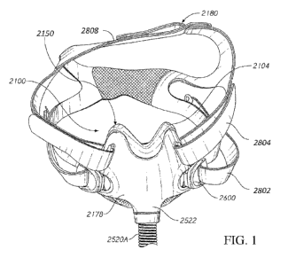
[0099] Figure 1 is a front and top perspective view of a mask assembly.
[0100] Figure 2A is a front, top and side perspective view of a mask assembly
with the
headgear omitted and an entirety of the air supply conduit shown.
[0101] Figure 2B is a rear, top and side perspective close-up view of the mask
assembly of
Figure 2A.
[0102] Figure 3A is a front view of a frame of the mask assembly of Figure 2A.
[0103] Figure 3B is a rear view of the frame of the mask assembly of Figure
2A.
[0104] Figure 4 is a side view of the frame of the mask assembly of Figure 2A.
[0105] Figure 5 is a side cross-sectional view of the frame of the mask
assembly of Figure 2A
taken along the line 5-5 of Figure 3A.
[0106] Figure 6 is a side cross-sectional view of the frame of the mask
assembly of Figure 2A
taken along the line 6-6 of Figure 3A.
[0107] Figure 7 is a front cross-sectional view of the frame of the mask
assembly of Figure
3A taken along the line 7-7 of Figure 4.
17
CA 03102591 2020-12-03
WO 2019/235939
PCT/NZ2019/050063
[0108] Figure 8 is a bottom view of the frame of the mask assembly of Figure
2A.
[0109] Figure 9 is a front, bottom, and side perspective exploded view of the
frame of the
mask assembly of Figure 2A.
[0110] Figure 10 is a rear, bottom, and side perspective exploded view of the
frame of the
mask assembly of Figure 2A.
[0111] Figure 11 is a side cross-sectional view of the frame of the mask
assembly of Figure
2A showing an inlet axis and a cushion connector axis.
[0112] Figure 12 is a front, top and side perspective view of a cushion module
of the mask
assembly of Figure 2A.
[0113] Figure 13 is a rear view of the cushion module of the mask assembly of
Figure 2A.
[0114] Figure 14 is a front view of the cushion module of the mask assembly of
Figure 2A.
[0115] Figure 15 is a side view of the cushion module of the mask assembly of
Figure 2A.
[0116] Figure 16 is a side cross-sectional view of the cushion module of the
mask assembly
of Figure 2A.
[0117] Figure 17 is a close-up rear view of a mask seal portion of the cushion
module of the
mask assembly of Figure 2A.
[0118] Figure 18 is a top view of the mask seal of the cushion module of the
mask assembly
of Figure 2A.
[0119] Figure 19A is a rear cross-sectional view of the mask seal of the mask
assembly of
Figure 2A taken along the line 19A-19A of Figure 18.
[0120] Figure 19B is a rear cross-sectional view of the mask seal of the mask
assembly of
Figure 2A taken along the line 19B-19B of Figure 18.
[0121] Figure 19C is a rear cross-sectional view of the mask seal of the mask
assembly of
Figure 2A taken along the line 19C-19C of Figure 18.
[0122] Figure 19D is a rear cross-sectional view of the mask seal of the mask
assembly of
Figure 2A taken along the line 19D-19D of Figure 18.
18
CA 03102591 2020-12-03
WO 2019/235939 PCT/NZ2019/050063
[0123] Figure 19E is a rear cross-sectional view of the mask seal of the mask
assembly of
Figure 2A taken along the line 19E-19E of Figure 18.
[0124] Figure 19F is a rear cross-sectional view of the mask seal of the mask
assembly of
Figure 2A taken along the line 19F-19F of Figure 18.
[0125] Figure 20A is a front and side perspective view of a cushion module
similar to the
cushion module of the mask assembly of Figure 2A.
[0126] Figure 20B is another version of a front and side perspective view of
the cushion
module of the mask assembly of Figure 20A with transitions or boundaries
between portions
of different thicknesses outlined.
[0127] Figure 21A is a front view of the cushion module of the mask assembly
of Figure
20A.
[0128] Figure 21B is an enlarged view of an upper portion of the cushion
module of the mask
assembly of Figure 20A.
[0129] Figure 21C is a side view of the cushion module of the mask assembly of
Figure 20A.
[0130] Figure 21D is a top view of the cushion module of the mask assembly of
Figure 20A.
[0131] Figure 21E is a rear cross-sectional view of the cushion module of the
mask assembly
of Figure 20A taken along the line of 21A-21A of Figure 21D.
[0132] Figure 21F is a side cross-sectional view of the cushion module of the
mask assembly
of Figure 20A taken along the line of 21B-21B of Figure 21D.
[0133] Figure 22A is a front view of the cushion module of the mask assembly
of Figure 20A
in neutral position.
[0134] Figure 22B is a front view of the cushion module of the mask assembly
of Figure 20A
when a laterally outward force is applied to each side of a nasal sealing
surface.
[0135] Figure 22C is a front view of the cushion module of the mask assembly
of Figure 20A
when a downward force is applied to the nasal sealing surface.
[0136] Figure 23 is a side view of the mask assembly of Figure 2A.
[0137] Figure 24 is a side cross-sectional view of the mask assembly of Figure
2A.
19
CA 03102591 2020-12-03
WO 2019/235939
PCT/NZ2019/050063
[0138] Figure 25 is a front view of the mask assembly of Figure 2A.
[0140] Figure 26 is a bottom view of the mask assembly of Figure 2A.
[0141] Figure 27A is a top cross-sectional view of the mask assembly of Figure
2A.
[0142] Figure 27B is a bottom view of the mask assembly of Figure 2A.
[0143] Figure 28 is a side view of an interface assembly showing a headgear
assembly.
[0144] Figure 29 is an exterior surface view of the headgear assembly of
Figure 28 in a laid
flat orientation.
[0145] Figure 30 is an interior surface view of the headgear assembly of
Figure 28 in a laid
flat orientation.
[0146] Figure 31A is a front, top, and side perspective view of an interface
assembly including a mask assembly and a headgear assembly with a yoke.
[0147] Figure 31B is a front and top perspective view of the interface
assembly of Figure
31A.
[0148] Figure 32 is a front view of the mask assembly of the interface
assembly of Figure
31A with the yoke.
[0149] Figure 33A is a front and side perspective view of the headgear
assembly of the
interface assembly of Figure 31A with the yoke.
[0150] Figure 33B is a side view of the headgear assembly of Figure 33A.
[0151] Figure 33C is a front view of the headgear assembly of Figure 33A.
[0152] Figure 34A is a front view of the yoke of the interface assembly of
Figure 31A.
[0153] Figure 34B is a rear view of the yoke of the interface assembly of
Figure 31A.
[0154] Figure 34C is a side view of the yoke of the interface assembly of
Figure 31A.
[0155] Figure 34D is a view of the yoke of the interface assembly of Figure
31A with a
portion of the yoke shown in outline form to illustrate underlying structure.
[0156] Figure 34E is a bottom view of the yoke of the interface assembly of
Figure 31A.
CA 03102591 2020-12-03
WO 2019/235939 PCT/NZ2019/050063
[0157] Figure 34F is an enlarged view of a portion of the bottom of the yoke
of the interface
assembly of Figure 31A as identified in Figure 34E.
[0158] Figure 34G is an enlarged view of a portion of a bottom cross-sectional
view of the
yoke of the interface assembly of Figure 32A taken along the line 34G-34G of
Figure 34D.
[0159] Figure 35A is a front and side perspective view of the frame of the
interface assembly
of Figure 31A.
[0160] Figure 35B is an enlarged cross-sectional view of a portion of the
frame of Figure
35A.
[0161] Figure 36 is a close up of a cross-sectional view of a portion of the
yoke and the mask
assembly of the interface assembly of Figure 31A.
[0162] Figure 37A is a front view of a yoke similar to the yoke of the
interface assembly of
Figure 31A.
[0163] Figure 37B is a rear view of the yoke of Figure 37A.
[0164] Figure 38 is front view of a mask frame of an interface assembly in
accordance with
aspects of this disclosure.
[0165] Figure 39 is a perspective view of the mask frame of Figure 38.
[0166] Figure 40 is a side view of the mask frame of Figures 39 and 39.
[0167] Figure 41 is a front perspective view of the mask frame of Figures 38
to 40 and a
yoke, with diffuser material omitted.
[0168] Figure 42 is a front perspective view of the mask frame of Figures 38
to 40 and a
further yoke, with diffuser material shown.
[0169] Figure 43 is a front view of the yoke of Figure 42.
[0170] Figure 44 is a front view of the yoke of Figure 42 with diffuser
material shown.
[0171] Figure 45 is front view of another mask frame of an interface assembly
in accordance
with aspects of this disclosure.
[0172] Figure 46 is a perspective view of the mask frame of Figure 45.
21
CA 03102591 2020-12-03
WO 2019/235939
PCT/NZ2019/050063
yoke, with diffuser material omitted.
[0173] Figure 47 is a front perspective view of the mask frame of Figures 45
to 46, with
diffuser material shown.
[0174] Figure 48 is a front perspective view of the mask frame of Figures 45
to 46, with a
diffuser and diffuser material removed from the mask frame.
[0175] Figure 49 is a sectional view through the diffuser of Figure 48.
[0176] Figure 50 is a sectional side view of the mask frame of Figures 45 to
46, with a
diffuser and diffuser material removed from the mask frame.
[0177] Figure 51 is a perspective view from the rear of a mask frame and mask
seal in
accordance with aspects of this disclosure.
[0178] Figure 52 is a perspective view from the rear of the mask frame of
Figure 51.
[0179] Figure 53 is a sectional side view of the mask frame and mask seal of
Figure 51.
[0180] Figure 54 is a rear perspective view of the mask frame and mask seal of
Figure 51.
[0181] Figure 55 is a perspective view from the front of the mask frame and
mask seal of
Figure 50.
[0182] Figure 56 is a rear view of the mask frame and mask seal of Figure 50.
[0183] Figure 57 is a front view of the mask frame and mask seal of Figure 50.
[0184] Figures 58 and 59 are perspective views from the rear of the mask frame
and mask
seal of Figure 50.
[0185] Figure 60 is a side view of the mask frame and mask seal of Figure 50.
[0186] Figure 61 is a front perspective view of another mask frame and mask
seal in
accordance with aspects of this disclosure.
[0187] Figure 62 is a view from underneath of the mask frame and mask seal of
Figure 61.
[0188] Figure 63 is a front view of the mask seal of Figure 62.
[0189] Figures 64 and 65 are perspective views of the mask seal of Figure 62.
22
CA 03102591 2020-12-03
WO 2019/235939 PCT/NZ2019/050063
[0190] Figures 66a and 66b are front and rear views of a diffuser for use with
the mask seal
of Figure 61.
[0191] Figures 67a and 67b are top and bottom views of the diffuser of Figure
66.
[0192] Figure 68 is a rear perspective view of the diffuser of Figure 68.
[0193] Figures 69 and 70 are front perspective views of the diffuser of Figure
68.
[0194] Figure 71 is a front view of the diffuser and mask seal of Figure 68.
[0195] Figure 72 is a front view of another diffuser for use with the mask
seal of Figure 62.
[0196] Figure 73 is a perspective front view of the diffuser and mask seal of
Figure 72.
[0197] Figure 74 is a perspective front view of another diffuser and mask
seal.
[0198] Figures 75a and 75b are front views of the mask seal of Figure 74.
[0199] Figure 76 is a cross sectional top view of the mask seal of Figure 75.
[0200] Figure 77 is a cross sectional front view of the mask seal of Figure
75.
[0201] Figures 78a and 78b are enlarged cross sectional top views of the part
of the mask seal
of Figure 75 shown in Box A of Figure 76.
[0202] Figures 79a and 79b are enlarged cross sectional top views of the mask
seal of Figure
75, with first and second vent hole configurations, and Figures 79c and 79d
are similar views
but with a wider recess and diffuser.
[0203] Figure 80 is an enlarged cross sectional top views of the mask seal of
Figure 75.
[0204] Figure 81 is an enlarged cross sectional top view of the mask seal of
Figure 75.
[0205] Figure 82 are enlarged cross sectional side views of the mask seal of
Figure 87.
DETAILED DESCRIPTION
[0206] Embodiments of systems, components and methods of assembly and
manufacture will
now be described with reference to the accompanying figures, wherein like
numerals refer to
like or similar elements throughout. Although several embodiments, examples
and
23
CA 03102591 2020-12-03
WO 2019/235939 PCT/NZ2019/050063
illustrations are disclosed below, it will be understood by those of ordinary
skill in the art that
the inventions described herein extend beyond the specifically disclosed
embodiments,
examples and illustrations, and can include other uses of the inventions and
obvious
modifications and equivalents thereof. The terminology used in the description
presented
herein is not intended to be interpreted in any limited or restrictive manner
simply because it
is being used in conjunction with a detailed description of certain specific
embodiments of
the inventions. In addition, embodiments of the inventions can comprise
several novel
features and no single feature is solely responsible for its desirable
attributes or is essential to
practicing the inventions herein described.
[0207] Certain terminology may be used in the following description for the
purpose of
reference only, and thus are not intended to be limiting. For example, terms
such as "above"
and "below" refer to directions in the drawings to which reference is made.
Terms such as
"front," "back," "left," "right," "rear," and "side" describe the orientation
and/or location of
portions of the components or elements within a consistent but arbitrary frame
of reference
which is made clear by reference to the text and the associated drawings
describing the
components or elements under discussion. For example, as the context may
dictate, the terms
"front" and/or forward can be used relative to components described herein
positioned
relatively or entirely distal to the user's face when the mask assembly as
described herein is
worn by the user. As the context may dictate, the terms "rear" and/or "back"
can be used
relative to components described herein positioned relatively or entirely
proximal to the
user's face and/or components that are forward or at the front of the mask
assembly when the
mask assembly as described herein is worn by the user. Moreover, terms such as
"first,"
"second," "third," and so on may be used to describe separate components. Such
terminology
may include the words specifically mentioned above, derivatives thereof, and
words of
similar import.
[0208] One or more of the embodiments described herein address issues with
sealing and
fitting a variety of facial (e.g., nasal) geometries that can be experienced
with face masks. In
particular, at least some of the embodiments are directed toward patient
interfaces, such as
face masks, which seal below the bridge of the user's nose and around the
nares. However,
the embodiments disclosed herein could also be adapted to other full face
masks (e.g., those
that partially cover and/or seal on the bridge of the user's nose), or an
under-nose nasal mask.
24
CA 03102591 2020-12-03
WO 2019/235939 PCT/NZ2019/050063
[0209] One or more of the embodiments described herein address issues with
creating a
satisfactory seal on a variety of facial geometries with an under-nose seal.
The reduced foot
print of an under-nose nasal or combined nasal and oral mask on the user's
face compared to
conventional nasal or full face masks that contact the nasal bridge can make
it more difficult
to maintain a seal with the user's face and be configured to adapt to various
facial geometries.
Sealing around and below the nose can present challenges due to the variation
seen in facial
geometries from user to user. One or more of the embodiments illustrated
herein can allow
for expansion of, for example, a nasal portion of the mask seal in response to
fitment on a
particular user or in response to pressure within the mask seal. In some
configurations, the
nasal portion of the mask seal can be configured to allow for relatively low
resistance to an
increase in width. Such an arrangement can allow a single mask seal to create
a satisfactory
seal with a user having a relatively narrow nose and a user having a
relatively wide nose. For
example, the width of the nasal portion may not expand or increase in width,
or may expand
or increase in width only slightly, when used with a user having a relatively
narrow nose. The
width of the nasal portion may expand or increase in width significantly or to
a maximum
extent when used with a user having a relatively wide nose. However, in at
least some
configurations, even when expanded, the nasal portion does not apply an
uncomfortable level
of force on the nose of the user. Such an arrangement advantageously can
maintain a
satisfactory seal between the user's face and the mask seal. An example of
such an
arrangement is disclosed in Applicant's PCT application No.
PCT/II32017/056146, the
entirety of which is incorporated by reference herein.
[0210] Figures 1-28 illustrate a mask assembly 2100 and components thereof,
both in
position on a face of a user and separated from the face of the user. The
illustrated mask
assembly 2100 comprises a cushion module 2150, which is a combined nasal and
oral
cushion module, such that the mask assembly 2100 can be referred to herein as
a nasal-oral or
oro-nasal mask. The illustrated cushion module 2150 is designed to seal under
the nose of the
user, along a portion of the face extending lateral to the nose, as well as
around the mouth of
the user. The cushion module 2150 advantageously does not require contact with
the bridge
of the nose of the user. In the illustrated configuration, the cushion module
2150 does not
extend over the bridge of the nose of the user. More particularly, the
illustrated cushion
module 2150 does not contact the bridge of the nose of the user. Even more
particularly, the
illustrated cushion module 2150 does not contact a forward-facing portion of
the bridge of the
nose of the user. In some configurations, the cushion module 2150 does not
contact the face
CA 03102591 2020-12-03
WO 2019/235939 PCT/NZ2019/050063
in a region vertically higher than a generally horizontal plane extending
along the lower
edges of the eyes of the user. The cushion module 2150 may or may not extend
over the tip of
the nose of the user. Thus, in some configurations, the cushion module 2150
covers the tip of
the nose. In some configurations, the seal of the cushion module 2150 covers
the tip of the
nose. In some configurations, the illustrated cushion module 2150 preferably
does not
enshroud the tip of the nose of the user. In some configurations or with some
facial
geometries, the tip of the nose of the user extends over the adjoining portion
of the cushion
module 2150.
[0211] As illustrated, the cushion module 2150 preferably is adapted to extend
around and
seal over the wing or alar of the nose, which flares out to form a rounded
eminence around
the nostril. The illustrated cushion module 2150 is adapted to seal around the
surfaces that
define the opening to the nostril, which may include a portion or entirety of
the fleshy
external end of the nasal septum, sometimes called the columella. In some
configurations, the
cushion module 2150 is adapted to extend upwardly to seal along at least a
portion of the left
and right dorsal side walls of the nose of the user. In some configurations,
the cushion
module 2150 is adapted to extend upwardly along at least a portion of the left
and right dorsal
side walls without extending upwardly to the region of the bridge of the nose
of the user. In
some configurations, a first sealing surface of the cushion module 2150
contacts the
underside of the nose of the user, possibly along with the upper lip and/or a
transition region
between the underside of the nose and the upper lip. A second sealing surface
of the mask can
contact the side surfaces of the nose of the user, possibly along with the
cheeks at a location
near the nose. Such primary and secondary sealing surfaces may not make
contact with the
face of all users; however, such an arrangement can provide a suitable seal
with a relatively
large range of facial geometries. The cushion module 2150 preferably also
seals around at
least a portion of the user's mouth. The cushion module 2150 may or may not be
adapted to
seal between the mouth and nose of the user.
[0212] As illustrated, the cushion module 2150 comprises a support structure.
In some
configurations, the support structure is a mask shell or housing 2102. A mask
seal or cushion
2104 can be attached to the housing 2102 such that the housing 2102 provides
some amount
of support for the mask seal 2104. However, in other configurations, the mask
seal 2104 may
not include a support and may be adapted for direct assembly to another
component of the
associated interface assembly. In some configurations, the housing 2102 can be
substantially
smaller than the illustrated housing 2102. For example, the housing 2102 can
define an
26
CA 03102591 2020-12-03
WO 2019/235939 PCT/NZ2019/050063
opening that allows the cushion module 2150 to be attached to another
component, such as a
frame and/or conduit connector (e.g., elbow) and the housing 2102 can be
localized to the
opening without providing direct support to other portions of the cushion
module 2150.
[0213] The housing 2102 can be formed from any suitable material. In some
configurations,
the housing 2102 is formed from a relatively hard material. In some
configurations, the
housing 2102 is formed from a hard plastic material, such as a polycarbonate
material. In
some configurations, the mask assembly 2100 can comprise a mask seal that
includes a mask
seal clip that is separate from but attachable to a housing. In such a
configuration, the mask
seal clip would connect the mask seal 2104 to the housing 2102. In such
configurations, the
mask seal and mask seal clip can be formed separately and secured together or
the mask seal
and the mask seal clip can be integrated into a single component. In some
configurations, the
mask seal can be over-moulded onto the mask seal clip and, in some
configurations, the mask
seal 2104 can be over-moulded directly onto the housing 2102, which can
comprise chemical
and/or mechanical over-moulding, for example.
[0214] In some configurations, the housing 2102 comprises a substantial
portion of a forward
wall of the cushion module 2150. Such an arrangement provides an advantageous
level of
support to the mask seal 2104. For example, the housing 2102 comprises a
substantial portion
of an oral portion of the forward wall of the cushion module 2150 or mask
assembly 2100. In
some configurations, the housing 2102 is generally limited to the oral portion
of the cushion
module 2150 or mask assembly 2100 and does not extend into the nasal portion
of the
cushion module 2150 or mask assembly 2100, at least to any significant extent.
Such an
arrangement can provide support to the mask seal 2104, while advantageously
permitting
movement or deformation of the nasal portion of the mask seal 2104. In other
arrangements,
the housing 2102 can extend into the nasal portion to provide additional
support to the nasal
portion, if desired.
[0215] The mask seal 2104 is designed to seal against the face of the user.
The mask seal
2104 preferably is formed of a soft material, such as silicone, for example
but without
limitation. In some configurations, at least portions of the mask seal 2104
can be textured to
improve comfort for the user. For example, in some configurations, at least
portions of the
mould used to form the illustrated mask seal 2104 can be bead blasted to
provide a surface
texture in at least the regions of the mask seal 2104 that will contact the
skin of the user.
Other techniques for texturing one or more surface of the mask seal 2104 can
be used. In
27
CA 03102591 2020-12-03
WO 2019/235939 PCT/NZ2019/050063
some configurations, it may be desirable to avoid surface texturing and
provide at least the
face-contacting surfaces of the mask seal 2104 with a smooth surface texture,
which may
increase grip of the mask seal 2104 on the user's face and improve sealing
characteristics.
[0216] The cushion module 2150 can be engaged with or otherwise supported by a
headgear
connector or frame 2178 that allows for connection to a head strap or headgear
2180 of any
suitable arrangement. Thus, the frame 2178 can be considered as a component of
the mask
assembly 2100. The mask assembly 2100 may also include an inlet tube, such as
a gas supply
conduit 2520A, connected to the frame 2178, among other possible components.
The cushion
module 2150 can be keyed to the frame 2178 to permit assembly in only the
correct
orientation. The headgear assembly 2180 can include straps, such as one or
more upper side
straps 2804, one or more lower side straps 2802, and/or a crown strap 2808,
among other
components (see Figures 25-27). In some configurations, the head strap or
headgear 2180
could be coupled directly to the cushion module 2150 and the frame 2178 can be
utilized for
other purposes or omitted. In such arrangements, the head strap or headgear
2180 could be
coupled to the housing 2102. Together, the frame 2178 and the headgear 2180
can support
the cushion module 2150 in place on the user's face. Collectively, the cushion
module 2150,
the frame 2178, gas supply conduit 2520A and the headgear 2180 can be referred
to as an
interface assembly. Although the illustrated mask assembly 2100 includes the
cushion
module 2150 that supports the seal 2104 and the frame 2178 that connects to
the headgear
2180, in other configurations a single integrated structure could both support
the seal 2104
and connect to the headgear 2180. For example, the housing 2102 of the cushion
module
2150 and the frame 2178 could be formed as an integrated structure, which
could be
simplified relative to the illustrated arrangement. Such a single integrated
structure is often
referred to as a "frame." Thus, references to the separate cushion module
2150/housing 2102
and frame 2178 in this disclosure could also refer to an integrated structure,
unless indicated
otherwise.
[0217] As shown in the illustrated example and as explained in more detail
below, the frame
2178 can include an anti-asphyxia (A-A) valve assembly 2522 (referred to
herein as the "A-A
valve 2522"). In some configurations, the A-A valve 2522 can be received by
the valve
recess 2726 of the cushion module 2150, as discussed below. As described in
more detail
below, the A-A valve 2522can include a valve housing. The A-A valve 2522can be
integrally
formed with the frame 2178. As described below, the A-A valve 2522can include
at least a
portion of the frame 2178, a valve element or valve member, such as a valve
flap 2524,
28
CA 03102591 2020-12-03
WO 2019/235939 PCT/NZ2019/050063
and/or a tube connector 2711, among other possible components. The A-A valve
2522 can be
located within the frame 2178 adjacent the air supply conduit 2520A. In some
embodiments,
the A-A valve 2522 can include an inlet tube positioned rearward of the front
wall of the
frame 2178. In some embodiments, the inlet tube can define at least a portion
of a gas flow
passage. In some configurations, the integration of the A-A valve 2522 with
the frame 2178
can allow the air supply conduit 2520A to extend in a generally downward
direction from a
lower front portion of the frame 2178. Such configurations can reduce the
overall bulkiness
of the patient interface. For example, in such configurations, the conduit
2520A can be
positioned closer to the user in use. The gas flow passage is provided by the
gas supply
conduit 2520A, the A-A valve 2522 and the cushion connector 2708. The gas flow
passage
provides a passage through which pressurized gas is delivered to the user's
nose and/or
mouth via the mask assembly 2100.
[0218] Figures 2A-2B illustrate an example of the mask assembly 2100. As
mentioned above,
the cushion module 2150 of the mask assembly 2100 can include the mask seal
2104 and
housing 2102, and is assembled to the frame 2178 and/or the air supply conduit
2520A,
among other components. The frame 2178 can be generally curved in a lateral
and/or a
vertical direction.
[0219] In some embodiments, the frame 2178 can be provided to a front side of
the cushion
module 2150. In some embodiments, the frame 2178 can cover a substantial
portion of the
front side of the cushion module 2150, such as a substantial portion of a
housing 2102 of the
cushion module 2150. In some embodiments, the frame 2178 is centered in the
lateral
direction along the front surface of the cushion module 2150. For example, the
entire front
surface of the frame 2178 can be positioned forward of the cushion module
2150.
[0220] Figures 3A-11 illustrate an embodiment of the frame 2178. In some
embodiments, the
frame 2178 can include a cushion connector 2708, an inlet or inlet opening
2706, the valve
2522, at least one upper strap connector 2702, at least one lower strap
connector 2704, and/or
upwardly extending supports 2179. The upwardly extending supports may be
referred to as
wings or paddles.
[0221] In some embodiments, the cushion connector 2708 can be positioned on a
rear side of
the frame 2178. In some embodiments, the cushion connector 2708 is unitary
with the frame
2178 and extends rearwardly from a rear surface of a front wall 2701 of the
frame 2178. The
29
CA 03102591 2020-12-03
WO 2019/235939 PCT/NZ2019/050063
cushion connector 2708 can provide a fluid connection between the inlet 2706
and the
cushion module 2150.
[0222] In some embodiments, the cushion connector 2708 can be shaped to fit
into at least a
portion of the cushion module 2150 to connect the frame 2178 to the cushion
module 2150.
For example, the cushion connector 2708 can fit into at least a receiving
portion of the mask
housing 2102, such as a frame connector 2730. The cushion connector 2708 can
include a
somewhat rounded `13' shape, a rounded trapezoidal shape, circular shape,
elliptical shape
and/or oval shape, among other possible shapes.
[0223] In some embodiments, the cushion connector 2708 is in the form of a
protruding wall
that forms a cuff or collar. The protruding wall can extend rearwardly and/or
upwardly from
the rear side of a front wall portion 2701 of the frame 2178. The cushion
connector 2708 can
be positioned above the A-A valve 2522 along the rear side of the frame 2178.
The cushion
connector 2708 can be positioned adjacent the A-A valve 2522 along the rear
side of the
frame 2178. In some configurations, the inlet 2706, the A-A valve 2522 and the
cushion
connector 2708 cooperate to form a gases flow passage defined by the frame
2178. In the
illustrated arrangement, each of the inlet 2706, the A-A valve 2522 and the
cushion connector
2708 includes a substantially enclosed space (e.g., with the exception of
specific and
deliberate openings) that defines a portion of the overall gases flow passage.
In some
configurations, the front wall portion 2701 of the frame 2178 defines at least
a portion of the
gases flow passage. In the illustrated arrangement, the front wall portion
2701 of the frame
2178 defines a portion of the gases flow passage in one or both of the A-A
valve 2522 and
the cushion connector 2708. Such an arrangement allows the frame 2178 to have
a reduced
depth in comparison to designs in which an entirety of the gases flow passage
is defined by
dedicated structure.
[0224] In some embodiments, the cushion connector 2708 can include an
alignment feature,
such as an alignment notch 2710. The alignment notch 2710 can be formed in a
portion of the
cushion connector 2710. For example, the alignment notch 2710 can be formed in
an upper
wall portion of the cushion connector 2708. The alignment notch 2710 can guide
the
connection between the frame 2178 and the mask assembly 2100. For example, the
alignment
notch 2710 can correspond to a feature on the mask assembly 2100 to allow the
frame 2178
and the mask assembly 2100 to be connected in a proper orientation. In some
embodiments,
the alignment notch 2710 has a generally trapezoidal shape, rectangular shape,
and/or square
CA 03102591 2020-12-03
WO 2019/235939 PCT/NZ2019/050063
shape, among other possible shapes. In some embodiments, the alignment notch
2710 can
have a width at a rearward edge of the upper wall of the cushion connector
2708 that is wider
than a width of the alignment notch 2710 at a position closer to the rear side
of the frame
2178.
[0225] In some embodiments, the frame 2178 can carry or otherwise include the
inlet 2706.
The inlet 2706 can be defined by a tube connector 2711, which can be a
separate structure
that is coupled to the frame 2178. In some embodiments, the inlet 2706 can
provide a fluid
flow path or gases flow passage through which pressurized air can be provided
to the mask
assembly 2100. In some embodiments, the pressurized air can be provided to the
mask
assembly 2100 through the inlet 2706 via the A-A valve 2522 or past the A-A
valve 2522. As
explained in more detail below, the A-A valve 2522 can provide access to
atmospheric air
when there is no pressurized air source or when the pressure within the mask
assembly 2100
otherwise drops below atmospheric pressure.
[0226] In some embodiments, the frame 2178 can include at least one upper
strap connector
2702 and at least one lower strap connector 2704. In the illustrated
arrangement, the frame
2178 includes a pair of upper strap connectors 2702 and a pair of lower strap
connectors
2704. Each of the pair of the upper and lower strap connectors 2702, 2704 can
be positioned
on opposite lateral sides of the frame 2178. In some embodiments, the upper
strap connectors
2702 can slidably receive the corresponding upper headgear straps 2804 of the
headgear 2180
(e.g., see Figure 1). With reference to Figure 4, the upper headgear
connectors 2702 can
include a post 2703A and an aperture 2703B. The post 2703A can be spaced away
from a
front surface of the frame 2178. The post 2703A can be positioned at
approximately a center
of the aperture 2703B. In some embodiments, the post 2703A can be positioned
offset from
the center of the aperture 2703B. In some embodiments, the post 2703A can be
offset
forward of a front wall of the frame 2178.
[0227] As shown in at least Figures 1 and 28, the post 2703A can help to
secure the upper
side strap 2804 to the upper headgear connector 2702. In some embodiments, the
post 2703A
together with the front surface of the frame 2178 can define a slot through
which the
corresponding upper side strap 2804 can pass. For example, the upper side
strap 2804 can
pass through the slot formed between the post 2703A and the aperture 2703B.
Once the upper
side strap 2804 passes through the slot, the upper side strap 2804 can be
wrapped around an
outer side of the post 2703A and folded over on itself, for example. In some
embodiments,
31
CA 03102591 2020-12-03
WO 2019/235939 PCT/NZ2019/050063
the aperture 2703B can provide additional space to allow the upper side strap
2804 to pass
behind the post 2703A. In some configurations, the aperture 2703B can help to
decrease a
distance between the post 2703A and the front surface of the frame 2178
necessary to
accommodate the thickness of the strap 2804. In some embodiments, the upper
strap
connectors 2702 can secure, such as removably secure, a headgear clip that can
be attached to
the upper side straps 2804.
[0228] In some embodiments, the lower strap connector 2704 can receive and/or
secure the
lower side strap 2802 and/or a lower headgear clip 2600 (see Figure 1). As
identified in
Figure 4, the lower strap connector 2704 can include a lower post 2705A. The
lower post
2705A can be positioned along a side edge of the frame 2178. The lower post
2705A can be
spaced away from a portion of the frame 2178 to define an aperture 2705B. In
some
embodiments, the lower post 2705A forms a lower lateral edge of the frame
2178. In some
embodiments, the aperture 2705B can be shaped to receive at least a portion of
the lower
headgear clip 2600. In some embodiments, the aperture 2705B can be
substantially D-shaped,
among other possible shapes. In some embodiments, the post 2705A can be
received within
and/or retain a portion of the corresponding lower headgear clip 2600, such as
a hook portion
of the clip 2600. The aperture 2705B may be sized and shaped to accommodate
the hook
portion of the clip 2600. The lower post 2705A can provide a removable
connection between
the lower side straps 2804 and the frame 2178 and/or the lower headgear clips
2600 and the
frame 2178.
[0229] In some embodiments, the frame 2178 can include the upwardly extending
supports
2179. The upwardly extending supports 2179 extend upwardly from opposite sides
of a
central portion of the frame 2178. The upwardly extending supports may be
referred to as
"frame paddles." As described above, the upwardly extending supports 2179 can
define upper
support members that provide support to forward facing lateral sides (upwardly
extending
portions 2126 of the seal 2104) of a nasal region 2168 of the mask seal 2104
when
assembled. The upwardly extending supports 2179 can help to minimize
deflection of the
mask seal 2104. In some embodiments, the upwardly extending supports 2179 can
help to
maintain contact between the nasal region 2168 and the user's nose. For
example, the
upwardly extending supports 2179 can help to prevent the nasal region 2168 and
the
upwardly extending portions 2126 of the mask seal 2104 from inflating away
from and/or
disengaging from the user's nose while allowing an internal wall of the
upwardly extending
portions 2126 to deflect outwardly. The upwardly extending supports 2179 each
have curved
32
CA 03102591 2020-12-03
WO 2019/235939 PCT/NZ2019/050063
upper edges. The upwardly extending supports 2179 each form semi-circular or D-
shaped
panels. The panels are located below and to either side of the wearer's nose
in use. A curved
trough is formed in the upper edge of the frame 2178 between the upwardly
extending
supports 2179.
[0230] Figures 4-10 illustrate certain portions of the valve 2522 in greater
detail. As shown in
at least Figures 4-6, 9 and 10, the valve 2522 can include a valve element or
valve member,
such as a valve flap 2524. The valve 2522 can also include a tube connector
2711, among
other possible components. In some embodiments, the valve 2522 can include
vent paths
2722 and/or outlets 2720. As illustrated, at least a portion or some
components of the valve
2522 can be integrally formed with the frame 2178. For example, the body
portions that
define the gases flow passage(s) of the valve 2522 are integrally formed with
the frame 2178.
Some configurations can desirably reduce assembly time and/or reduce the
number of
components necessary to manufacture, clean and/or replace. Some such
configurations can
desirably reduce the likelihood that pressurized air will leak from the
assembly.
[0231] Figure 5 and Figure 6 illustrate side cross-sectional views of the
frame 2178 along the
lines 5-5 and 6-6 shown in Figure 3A, respectively. Figure 7 illustrates a
front cross-sectional
view of the frame 2178 along the line 7-7 shown in Figure 4. As illustrated,
the frame 2178
can house the valve flap 2524. In some embodiments, the frame 2178 entirely
surrounds a
perimeter of a movable portion of the valve flap 2524. As such, the movable
portion of the
valve flap 2524 can be positioned to fit within a gases flow passage of the
valve 2522 of the
frame 2178.
[0232] In some embodiments, the tube connector 2711 can define the inlet
opening 2706 that
directs pressurized air through the valve 2522 to the user through the mask
assembly 2100. In
some embodiments, the tube connector 2711 can be elliptical shaped, circular
shaped, and/or
oval shaped, among other shapes. Preferably, a dimension of the inlet 2706 in
a forward-
rearward direction is smaller than a dimension of the inlet 2706 in a lateral
direction.
Accordingly, extra space is provided to accommodate the valve 2522 in a
forward-rearward
direction in comparison to a design in which the inlet 2706 is circular,
without increasing the
forward-rearward dimension of the frame 2178 or moving the inlet 2706 further
away from
the user's face.
[0233] The tube connector 2711 can include a male component that is received
by a
corresponding female connector. The female connector may be attached to the
conduit
33
CA 03102591 2020-12-03
WO 2019/235939 PCT/NZ2019/050063
2520A. In some embodiments, the tube connector 2711 can allow for
disconnection of the
conduit 2520A by twisting the conduit 2520A relative to the frame 2178 and/or
the tube
connector 2711. In some embodiments, the conduit 2520A is connected to the
tube connector
2711 by a snap-fit configuration, among other possible configurations. For
example, the tube
connector 2711 can include one or more tube connector notches 2712. The tube
connector
notches 2712 can engage corresponding features on the conduit 2520A via the
snap-fit
configuration.
[0234] In some embodiments, the valve flap 2524 can be secured within the
frame 2178 by
the tube connector 2711. In some embodiments, the tube connector 2711 can be
permanently
connected to a lower end of the frame 2178 that defines the valve 2522 by
various
configurations, such as welding, adhesive, and/or a snap-fit configuration,
among other
possible configurations. In some embodiments, the tube connector 2711 can
surround and/or
secure a tab of the valve flap 2524 between the lower end of the frame 2178
and a flange of
the tube connector 2711. In some embodiments, the valve flap 2524 can be
positioned
adjacent an inner end of the tube connector 2711 within the frame 2178. In
some
embodiments, the valve flap 2524 can be constructed in whole or in part from a
flexible
elastomer, such as silicone, among other materials.
[0235] The valve flap 2524 can open and close different flow paths within the
valve 2522 to
allow air to flow through a desired one of the different flow paths of the
valve 2522. For
example, when a flow generator supplies positive pressure air to the user
through the mask
assembly 2100, the valve flap 2524 can pivot about a hinge or otherwise move
in response to
the pressurized air entering the inlet 2706. In this position, the valve flap
2524 is opened
relative to the inlet 2706 of the tube connector 2711, and is closed relative
to the valve 2522
and/or vent paths 2722 of the valve 2522. Some configurations can help to
ensure that all or
substantially all of the positive pressure airflow is directed to the user
with little to no airflow
leaking from the vent paths 2722 of the valve 2522. When a flow generator does
not provide
airflow to the mask assembly 2100 or the pressure within the mask assembly
2100 otherwise
drops below atmospheric pressure, the valve flap 2524 closes relative to the
inlet 2706 of the
tube connector 2711 and the vent paths 2722 of the A-A valve 2522 are opened
to allow the
user in inhale ambient air through the valve 2522.
[0236] The tube connector 2711 can support the valve flap 2524 in an operable
position
relative to the valve 2522 portion of the frame 2178. In some configurations,
the tube
34
CA 03102591 2020-12-03
WO 2019/235939 PCT/NZ2019/050063
connector 2711 defines a stop that prevents the valve flap 2524 from inverting
or extending
downwardly out of the inlet 2706 of the frame 2178 (see, e.g. Figure 5). In
some
configurations, the tube connector 2711 can include a flap support 2724. In
some
embodiments, the tube connector 2711 can include at least three flap supports
2724 (see
Figure 8). In some embodiments, the tube connector 2711 can includes at least
two, three,
four, five, or six or more flap supports 2724. The flap supports 2724 can
extend radially
inwardly from an inner surface of a perimeter wall of the tube connector 2711
into the inlet
2706 of the tube connector 2711. In some embodiments, the flap supports 2724
can be
positioned adjacent an upper edge of the tube connector 2711. In some
configurations, the
flap supports 2724 can prevent the valve flap 2524 from inverting or extending
downwardly
into the inlet 2706.
[0237] As shown in at least Figure 7, the valve 2522 (alone, or in combination
with the frame
2178) can include various vent paths and valve outlets to allow air to flow in
and out of the
mask assembly 2100 when the valve flap 2524 is in the closed position. For
example, in some
embodiments, a flow path is provided through the vent paths 2722 and valve
outlets 2720 of
the valve assembly 2522. In some embodiments, the valve 2522 can include at
least two vent
paths 2722 and/or at least two lateral valve outlets 2720.
[0238] In some embodiments, the vent paths 2722 can extend rearwardly away
from the inlet
2706 towards the outlets 2720. In some embodiments, the vent paths 2722 can
extend through
an internal wall of the valve 2522 towards the outlets 2720. In some
embodiments, the vent
paths 2722 can extend through an internal wall of the valve 2522 towards the
outlets 2720. In
some embodiments, the vent paths 2722 can extend rearwardly and downwardly
into the
outlets 2720. In some embodiments, a central axis of the vent paths 2722 forms
an acute
angle with the central axis 2706A (as shown in Figure 11) of the inlet 2706.
[0239] In some embodiments, the outlets 2720 can define an opening to allow
exhausted air
to pass out of the patient interface or inhaled air to enter the patient
interface, via the vent
paths 2722 when the valve flap 2524 is in the closed position relative to the
inlet 2706. As
shown in Figure 6, the valve 2522 can include a rear wall 2523 that is spaced
rearwardly
away from an outlet of the vent paths 2722 on the side of the outlets 2720 and
defines a
rearward extend of the outlets 2720. Such configurations can provide a space
to direct the
exhausted air in a lateral direction, as indicated by arrows shown in Figure
3B. The rear wall
2523 of the valve 2522 can allow the exhausted air to be directed away from
the user. In
CA 03102591 2020-12-03
WO 2019/235939 PCT/NZ2019/050063
some embodiments, exhausting the air in the lateral direction can help to
minimize contact
between the exhausted air and the user. Some configurations can help to reduce
discomfort
caused to the patient by the exhausted air. In some embodiments, the outlets
2720 can extend
below a lower surface of the housing 2102 of the cushion module 2150 when
assembled (see
Figures 23 and 24). In such configurations, the exhausted air may not be
blocked by the
housing 2102.
[0240] Figures 9 and 10 illustrate exploded views of the frame 2178 showing
portions of the
valve 2522. In some embodiments, the valve flap 2524 can include an outer
perimeter 2524A
and an interior rib 2524B. The outer perimeter 2524A can include a lip. The
lip can define a
thickened region that extends along the outer perimeter 2524A. In some
embodiments, the rib
2524B can be positioned along a lower side of the valve flap 2524. The rib
2524B can be
positioned approximately along a central axis of the valve flap 2524. In some
embodiments,
the rib 2524B can define a thickened region along the center of the valve flap
2524. In some
embodiments, the outer perimeter 2524A and/or the rib 2524B can provide
rigidity to the
valve flap 2524. The outer perimeter 2524A and/or the rib 2524B can help to
inhibit
ballooning and/or deformation of the valve flap 2524 caused by the pressurized
airflow in
use. Some configurations can help to provide an effective seal around the vent
paths 2722
when the valve 2522 is in the opened position relative to the inlet 2706.
[0241] In some embodiments, the tube connector 2711 can define the inlet 2706
that directs a
source of pressurized air through the valve 2522 into the breathing chamber of
the cushion
module 2150. The inlet 2706 can be angled downwards in use. For example, as
shown in
Figure 11, a central axis 2706A of the inlet 2706 can form an angle with a
central axis 2708A
of the cushion connector 2708. In some embodiments, the angle is approximately
125
degrees. In some embodiments, the angle is greater than or less than 125
degrees. In some
embodiments, the angle is approximately 124.4 degrees. In some embodiments,
the angle is
greater than or less than 124.4 degrees. Some configurations can help to keep
the conduit
2520A away from the user. Some configurations can desirably minimize the
bulkiness of the
patient interface, such as at the front of the mask assembly 2100.
[0242] Figures 12 and 14 illustrate a front of the cushion module 2150 showing
the housing
2102. In some embodiments, the housing 2102 can include one, two, three, four,
or five, or
more bias vents 2502. The bias vents 2502 can be positioned at a bottom region
of the
housing 2102. In some embodiments, the bias vents 2502 can be positioned on a
generally
36
CA 03102591 2020-12-03
WO 2019/235939 PCT/NZ2019/050063
forward facing surface of the housing 2102. For example, the bias vents 2502
can be
positioned adjacent a lower edge of the housing 2102. In some configurations,
holes of the
bias vents 2502 can be positioned close to and/or adjacent the lower edge of
the frame 2178
when assembled. Preferably, the bias vents 2502 are positioned below a lower
edge of the
frame 2178. Such configurations can minimize contact between vented air and
the frame
2178. Such configurations can help to reduce noise and/or undesirable drafts
or air leaks.
[0243] Figure 14 shows an example of the housing 2102 including two bias vents
2502. The
bias vents 2502 can include a plurality of holes. The plurality of holes can
be arranged in a
generally triangular pattern, among other possible patterns. The bias vents
2502 can be
positioned on opposing lateral sides of an inlet 2732 and/or valve recess 2726
of the cushion
module 2150. In some embodiments, at least a portion of the bias vents 2502 is
positioned
below at least a portion of the inlet 2732 and at least a portion of the bias
vents 2502 is
positioned beyond a side of the inlet 2732. In such configurations, only a
portion of the bias
vents 2502 is positioned laterally beyond the inlet 2732. In some embodiments,
the bias vents
2502 are positioned entirely beyond a side of the inlet 2732. The bias vents
2502 can be
configured to help disperse the exhausted air. Such configurations can reduce
disturbance,
such as draft and/or noise, caused by the exhausted air to the user and/or the
user's bed
partner.
[0244] In some embodiments, the bias vents 2502 are positioned such that air
is exhausted
below the frame 2178 (see Figures 23-25). For example, the bias vents 2502 are
positioned
immediately below and/or adjacent a lower edge of the frame 2178. Such
configurations can
allow vented air to pass the frame 2178 with little or minimal disturbance to
airflow. As
discussed above, such configurations can help to disperse the exhausted air,
reduce noise,
and/or reduce disturbance caused by the exhausted air.
[0245] In some embodiments, the housing 2102 includes the valve recess 2726.
The valve
recess 2726 can define a concave region. The concave region can be positioned
below and/or
adjacent the inlet 2732. In some embodiments, the valve recess 2726 can have a
width that is
less than a maximum width of the inlet 2732.
[0246] As described above, the valve recess 2726 can receive at least a
portion of the A-A
valve 2522, such as a rear portion of the A-A valve 2522 and/or the valve
outlets 2720. In
some embodiments, the valve recess 2726 has a curved surface that includes a
curvature
accommodating or matching a curvature of a rear surface/wall 2523 of the A-A
valve 2522.
37
CA 03102591 2020-12-03
WO 2019/235939 PCT/NZ2019/050063
In at least some embodiments, the valve recess 2726 allows the A-A valve 2522
to be
positioned recessed into the cushion module 2150 and/or below at least a
portion of the mask
seal 2104, such as a forward upper portion and/or the nasal region 2168 of the
mask seal
2104. In at least some embodiments, the valve recess 2726 and/or the A-A valve
2522 can
desirably reduce an overall depth of the patient interface. This can help to
reduce the
obtrusiveness of the patient interface to the user and reduce hose pull. In at
least some
embodiments, the valve recess 2726 and/or the A-A valve 2522 can allow the A-A
valve
2522 to be positioned higher relative to the bottom of the mask seal 2104
and/or the inlet
2732 to be shorter. This can help to reduce the overall size of the mask
assembly 2100.
[0247] As mentioned above, the housing 2102 can include the frame connector
2730. As
shown in Figure 12, the frame connector 2730 can form a collar. The collar can
protrude
inwardly from a front surface of the housing 2102 toward or into an interior
of the cushion
module 2150. The frame connector 2730 can extend around an entirety or a
portion of a
perimeter of the inlet 2730. In some embodiments, the frame connector 2730 can
receive
and/or retain the cushion connector 2708 of the frame 2178.
[0248] In some embodiments, the frame connector 2730 can include a securement
feature to
engage the cushion connector 2708 of the frame 2178. For example, the frame
connector
2730 can include at least one connector bump 2734 (e.g., a pair of connector
bumps 2734) or
other retention or alignment features. The connector bump 2734 can be
positioned along a
portion of an interior surface of the frame connector 2730. The connector bump
2734 can
engage with a corresponding engagement feature 2715 of the cushion connector
2708. The
engagement feature 2715 can include a notch, recess, or other engagement
feature. The
engagement feature 2715 can be positioned on an outer surface of the cushion
connector
2708. In some embodiments, the connector bump 2734 can engage with the
engagement
feature 2715 of the cushion connector 2708 by a snap-fit arrangement, among
other
engagement arrangements. In some embodiments, the cushion connector 2708
includes a pair
of laterally opposed recesses 2715 that are configured to receive and/or
retain a
corresponding pair of connector bumps 2734 on the frame connector 2730. Such
configurations can secure the frame 2178 to the cushion module 2150.
[0249] As shown in at least Figures 16 and 24, in some embodiments, the frame
connector
2730 can include a lip 2738. The lip 2738 can define an upper wall of the
valve recess 2726.
In some configurations, the lip 2738 can be recessed relative to a front side
of the housing
38
CA 03102591 2020-12-03
WO 2019/235939 PCT/NZ2019/050063
2102. In some embodiments, the lip 2738 can form at least a portion of the
frame connector
2730 and/or the inlet 2732. When assembled, the lip 2738 can be positioned
above the valve
outlet 2720.
[0250] As described above, the frame connector 2730 can include an alignment
feature 2714.
The alignment feature 2714 can protrude radially into the inlet and/or forward
of a rear edge
of the frame connector 2730. The alignment feature 2714 can engage with the
alignment
notch 2710 of the cushion connector 2708 of the frame 2178. Such
configurations can help to
align and/or secure the frame 2178 to the mask seal 2104.
[0251] In some embodiments, the mask seal 2104 is substantially resilient. In
some
embodiments, the mask seal 2104 can include a nasal region 2168 and an oral
seal portion.
The nasal region 2168 can include a nasal opening 2124 and right and left
nasal sealing
surfaces 2124A, 2124B. The right and left nasal sealing surfaces 2124A, 2124B
can extend
outwardly from the nasal opening 2124. In some embodiments, the oral seal
portion can
include an oral opening 2122 (see Figure 13).
[0252] As shown in at least Figures 13-14, the cushion module 2150 can include
the inlet
2732. The inlet 2732 can form an opening in the cushion module 2150 to allow
air to flow
into the breathing chamber. In some embodiments, the inlet 2732 can include a
noncircular
perimeter. In some embodiments, the perimeter of the inlet 2732 is generally
oval-shaped,
elliptical-shaped, square-shaped, and/or rectangular-shaped, among other
shapes. In some
embodiments, the inlet 2732 includes a generally rounded 'D' shape and/or a
rounded
trapezoidal shape, among other shapes. The inlet 2732 having a non-circular
perimeter can
desirably help to more easily assemble and/or align the frame 2178 and the
cushion module
2150. Such configurations can help to prevent incorrect assembly of the seal
2104 to the
frame 2178. Such configurations can help to inhibit or limit rotation of the
frame 2178
relative to the cushion module 2150 when assembled. In some embodiments, the
noncircular
perimeter of the inlet 2732 can allow at least a portion of the valve 2522 to
be positioned
closer to a center of the inlet 2732 than a design having a circular inlet
2732, since such non-
circular configuration of the inlet 2732 will have smaller height than the
circular inlet 2732.
Such non-circular configurations can desirably create additional space for the
valve 2522,
thereby reducing the overall size (e.g., height) of the mask assembly 2100
when assembled in
comparison to a mask having a circular inlet.
39
CA 03102591 2020-12-03
WO 2019/235939 PCT/NZ2019/050063
[0253] As discussed above, the mask seal 2104 can include the nasal region
2168. The nasal
region 2168 can include left and right sealing surfaces 2124B, 2124A. In some
embodiments,
each of the left and right sealing surfaces 2124B, 2124A can define a convex
region. As
described previously herein, the left and right sealing surfaces 2124B, 2124A
cooperate to
define a concave region, which is configured to receive the user's nose. The
convex region of
the left and right sealing surfaces 2124B, 2124A can be generally flattened.
For example, the
flattened convex region can extend from a top of the left and right sealing
surfaces 2124B,
2124A towards the nasal opening 2124. The flattened convex region can have a
generally
linear profile as the left and right sealing surfaces 2124B, 2124A extends
from the uppermost
point towards the nasal opening 2124. The flattened sealing surfaces 2124B,
2124A can help
to prevent or limit creases forming in the sealing surfaces 2124B, 2124A when
the nasal
region 2168 engages the user's nose in use, for example. Some configurations
can help to
minimize leaks around the user's nose in use.
[0254] Figure 17 illustrates a close-up rear view of a portion of the nasal
region 2168.
Though the left nasal sealing surface 2124B is shown and described, the right
nasal sealing
surface 2124A can include similar features and, preferably, is a mirror-image
of the left nasal
sealing surface 2124B. As shown, the nasal sealing surface 2124B can be
relatively flat
laterally adjacent to the nasal opening 2124. In some embodiments, the
curvature of the nasal
sealing surface 2124B can be relatively low (e.g., approximately linear) as
the nasal sealing
surface 2124B extends radially outward from the nasal opening 2124 towards the
uppermost
point of the nasal sealing surface 2124B. In some embodiments, the curvature
of the nasal
sealing surface 2124B can be relatively low as the nasal sealing surface 2124B
extends
radially outward from the nasal opening 2124 to approximately a midpoint 2725
of the nasal
sealing surface 2124B, as illustrated by the lines of curvature 2727A, 2727B,
2727C, 2727D,
2727E. In some embodiments, the curvature of the nasal sealing surface 2124B
increases as
the nasal sealing surface 2124B extends radially outward beyond the midpoint
2725 (e.g., at
an outer nasal sealing surface region).
[0255] As indicated by a curve plot 2728 and as described in more detail
below, the radius of
curvature of the outer nasal sealing surface region decreases in a rearward to
forward
direction along the surface of the outer nasal sealing surface region. For
example, in some
embodiments, the radius of curvature of the outer nasal sealing surface region
at the rearward
portion of the nasal sealing surface 2124B is larger than the radius of
curvature of the outer
nasal sealing surface region at the forward portion of the nasal sealing
surface 2124B. That is,
CA 03102591 2020-12-03
WO 2019/235939 PCT/NZ2019/050063
the nasal sealing surface 2124B can go from less curved to more curved moving
in a rearward
to forward direction.
[0256] Figure 18 shows a top view of the mask seal 2104. Figures 19A-19F are
sectioned
views as viewed from the rear of the mask seal 2104. As shown, in some
embodiments, the
left and right nasal sealing surfaces 2124B, 2124A can be angled away from
each other in at
least two dimensions. For example, when viewed from the front or rear, the
left and right
nasal sealing surfaces 2124B, 2124A can extend upwardly away from the nasal
region 2168
at an angle to form a generally V-shape. In some embodiments, when viewed from
the top,
the left and right nasal sealing surfaces 2124B, 2124A can be angled away from
each other in
a direction from a front 2740 to a rear 2742 of the mask seal 2104 or seal
assembly 2100. In
such configurations, the nasal region 2168, including the left and right nasal
sealing surfaces
2124B, 2124A can form a generally triangular shape. Such configurations can
desirably
accommodate or generally match the geometry of a user's nose. This can provide
more
stability and/or comfort to the user. Such configurations can help to reduce
leakages of air
from the mask seal 2104.
[0257] Figure 19A illustrates a rear cross-sectional view taken along line 19A-
19A of Figure
18. Figure 19B illustrates a rear cross-sectional view taken along line 19B-
19B of Figure 18.
Figure 19C illustrates a rear cross-sectional view taken along line 19C- 19C
of Figure 18.
Figure 19D illustrates a rear cross-sectional view taken along line 19D- 19D
of Figure 18.
Figure 19E illustrates a rear cross-sectional view taken along line 19E-19E of
Figure 18.
Figure 19F illustrates a rear cross-sectional view taken along line 19F-19F of
Figure 18. As
shown in Figures 19A-19F, the left and right nasal sealing surfaces 2124B,
2124A of the
nasal region 2168 can be angled outwardly and upwardly away from each other,
and from the
central vertical plane, in a bottom to top direction. In some embodiments, an
angle between
the left and right nasal sealing surfaces 2124B, 2124A increases in a rear to
front direction. In
some embodiments, a depth of the nasal region 2168 decreases in a rear to
front direction. For
example, the angle 2744A can be approximately 57 degrees, the angle 2744B can
be
approximately 60 degrees, the angle 2744C can be approximately 64 degrees, the
angle
2744D can be approximately 71 degrees, the angle 2744E can be approximately 77
degrees,
the angle 2744F can be approximately 88 degrees, and angles therebetween such
ranges.
Such configurations can allow the nasal region 2168 to engage with the user's
nose in use
without extending over the tip of the user's nose. Such configurations can
desirably better
41
CA 03102591 2020-12-03
WO 2019/235939 PCT/NZ2019/050063
match the geometry of a user's nose. This can provide more stability and/or
comfort to the
user. Such configurations can help to reduce leakages of air from the mask
seal 2104.
[0258] Figures 20A-22C illustrates various views of the cushion module 2150
including the
mask seal 2104 and the housing 2102 according to one embodiment. The mask seal
2104
preferably comprises a pair of upwardly extending portions or upward
extensions 2126 (see,
for example, FIG. 21A). The upwardly extending portions 2126 extend upwardly
from
opposite sides of a central sealing surface of the seal. The central sealing
surface is provided
in a central portion of the mask seal 2104. The upwardly extending portions
may be referred
to as "seal paddles." The upper surface 2130 can define a line that lies along
the central
surface of the nasal region 2168 of the mask seal 2104 in a fore-aft
direction. Such a line
extends generally along the nasal septum in a direction away from the user's
face. The
upwardly extending portions 2126 are configured to extend upward alongside,
and in some
configurations above, the nares. The upwardly extending portions 2126 can
contact the edges
of the nares and/or sides of the nose. The upwardly extending portions 2126 or
portions of the
mask seal 2104 between the upwardly extending portions 2126 may or may not
cover the tip
of the user's nose. As described herein, preferably the mask seal 2104 does
not contact the
bridge of the user's nose.
[0259] In some configurations, the upwardly extending portions 2126 each
comprise an air
pocket that is formed by an internal wall (including nasal sealing surface
2124A,B) and an
external wall of the upwardly extending portions 2126. Such air pocket may be
in direct fluid
communication with the air path through the mask assembly 2100, such that the
upwardly
extending portions 2126 can be configured to expand in volume in response to
elevated
pressure within the mask seal 2104 and/or flex inwardly to accommodate various
facial and
nasal geometries and assist in creating a sealed contact with the user's face.
Expansion of the
upwardly extending portions 2126 can assist in sealing against the face of the
user, especially
along the varying contours on and around the user's nose. Inward flexing of
the upwardly
extending portions 2126 allows the central portion (e.g., upper surface 2130)
to move
downward with less restriction or less stretching of the material of the mask
seal 2104 so that
the mask seal 2104 can better conform to various nasal geometries.
[0260] The height of the upwardly extending portions 2126 above the upper
surface 2130 can
be selected to provide a desired balance between stability of the mask seal
2104 on the user's
face (e.g., vertical stability) and being able to accommodate a range of nasal
geometries or
42
CA 03102591 2020-12-03
WO 2019/235939 PCT/NZ2019/050063
reducing visual disruption by the upwardly extending portions 2126. In
general, taller
upwardly extending portions 2126 tend to provide additional vertical stability
of the mask
assembly 2100, while shorter upwardly extending portions 2126 tend to provide
a better fit of
a wider range of users and result in less visual disruption. In some
configurations, the height
of the upwardly extending portion 2126 is between about 10 mm and about 30 mm
or
between about 15 mm and about 25 mm. In some configurations, the height of the
upwardly
extending portion 2126 is between about 15 mm and about 22 mm or between about
18 mm
and about 20 mm, including any value or sub-range within the above described
ranges. In
some configurations, the height of the upwardly extending portion height is
about 18.5 mm.
[0261] The mask seal 2104 can also comprise support structures or supports
2163 for the
upwardly extending portions 2126, which can be in the form of suspension
members or
springs that provide mechanical rigidity and structure to hold the shape of
the upwardly
extending portions 2126 when the mask seal 2104 is worn by a user. The
supports 2163 can
comprise thickened regions of the seal material. The supports 2163 preferably
are sized,
shaped and/or otherwise configured to transfer force from a rearward or user-
contacting
surface of the upwardly extending portions 2126 toward or to a forward surface
of the
upwardly extending portions 2126. In some configurations, the interface
assembly can
include a support portion or cover for the upwardly extending portions 2126,
for example the
upwardly extending supports 2179, and the supports 2163 can transfer force
from the
rearward surface of the upwardly extending portions 2126 to the forward
surface or other
portion of the upwardly extending portions 2126 or mask seal 2104 that
contacts or faces the
upwardly extending supports 2179 or another portion of the frame 2178. In some
configurations, the supports 2163 can transfer force from the rearward surface
of the
upwardly extending portions 2126 toward or to another support portion of the
mask seal
2104, the housing 2102, or any other components of the interface assembly. The
supports
2163 can resist or prevent collapse of the upwardly extending portions 2126 or
other related
or adjacent portions of the mask seal 2104 to facilitate fitment and provide
feedback to the
user, such as in response to applied forces (e.g., headgear forces). In some
configurations, the
supports 2163 can resist or prevent collapse of the upwardly extending
portions 2126 or other
related or adjacent portions of the mask seal 2104 in the absence of
significant internal gas
pressure.
[0262] The supports 2163 can help maintain the shape of the upwardly extending
portions
2126 of the mask seal 2104 and/or help maintain a separation between a rear
wall of the mask
43
CA 03102591 2020-12-03
WO 2019/235939 PCT/NZ2019/050063
seal 2104 (defining a face contacting surface) and a front wall of the mask
seal 2104 at least
in response to forces experience during normal use. In addition, the supports
2163 can
provide support to the nasal region 2168. In particular, the supports 2163 can
provide
structure to and inhibit or prevent creasing, wrinkling or collapsing of the
nasal region 2168.
As described above, the nasal region 2168 preferably is relatively thin to
permit this portion
of the mask seal 2104 to conform to the user's nose. The relatively thin nasal
region 2168 can
expand and seal around the user's nose. The supports 2163 provide relatively
rigid portions
or elements of the seal 2104 adjacent or near the relatively thin nasal region
2168 to inhibit or
prevent collapse when a user engages his or her nose into the mask assembly
2100.
[0263] In some configurations, the supports 2163 help to reduce the likelihood
of wrinkling
or creasing of the nasal sealing surfaces 2124A, 2124B of the upwardly
extending portions
2126 during use while allowing the laterally inner portions to be as thin as
desired within
practical limitations. The supports 2163 can assist in inhibiting or
preventing collapse of the
upwardly extending portions 2126 or maintaining a desired shape of the
upwardly extending
portions 2126. For example, the supports 2163 can assist in maintaining a
desired fore-aft
shape of the upwardly extending portions 2126 and/or a lateral or side-to-side
shape of the
upwardly extending portions 2126. The level of support provided can vary in
different
directions. In some configurations, the supports 2163 could be formed as
separate portions or
separate components from the seal material and could be the same or a
different material.
Such separate supports 2163 could be coupled to the upwardly extending
portions 2126 or
other portion of the mask seal 2104 if desired. The supports 2163 disclosed
herein can be
particularly useful in under-nose type mask assemblies, including both nasal
masks and
combined nasal-oral masks. However, the supports 2163 can also be utilized in
other types of
mask assemblies or interfaces, including those that cover, contact or seal
against the bridge of
the user's nose and/or include a T-piece or other type of forehead support,
for example and
without limitation. The supports 2163 can be utilized, or modified for use, in
any locations of
an interface in which support against collapsing and/or support against
overexpansion may be
desirable. Such locations can be at or near the portion of the seal that
contacts or extends
alongside the user's nose or can be at other locations.
[0264] In the illustrated arrangement, at least a portion of the supports 2163
extend generally
in a fore-aft direction along the upwardly extending portions 2126. In
particular, the supports
2163 can extend along the upper edge 2169 of the upwardly extending portions
2126 or the
44
CA 03102591 2020-12-03
WO 2019/235939 PCT/NZ2019/050063
region or ridge that joins the nasal sealing surfaces 2124A and 2124B along
the upper edges
2169 of the upwardly extending portions 2126. The supports 2163 can extend
along a portion
of the sides of the nasal region 2168. The supports 2163 can comprise a
generally narrow,
elongate shape. Viewed from above, the supports 2163 can comprise a generally
triangular
shape with a base of the triangle positioned rearwardly of the top or point of
the triangle.
Viewed from side, the supports 2163 can comprise a generally sickle or
crescent shape. Other
shapes are possible to achieve a desired level of support or for other design
considerations,
such as the desired shape(s) of adjacent or nearby structures. The supports
2163 can have
additional portions to provide other levels of support or to provide support
in other directions.
For example, the supports 2163 could connect to one another, such as along one
or both of
the forward or rearward sides of the nasal opening 2124. In some
configurations, the supports
2163 could extend completely through the upwardly extending portions 2126,
such as to the
housing 2102, for example.
[0265] The illustrated mask seal 2104 of the cushion module 2150 comprises a
range and
configuration of thicknesses. The thicknesses are varied to take advantage of
or provide
different characteristics in different regions of the illustrated mask seal
2104. For example,
the thicknesses in the various regions can be selected to address a desired
characteristic for
that region and/or the mask seal 2104 as a whole. Such characteristics can
include, for
example, allowing the mask seal 2104 to conform to the facial geometry of the
user to
enhance sealing properties or comfort, supporting the shape of the mask seal
without
significant internal gas pressure to facilitate fitment and/or in response to
internal gas
pressure and/or external pressure (e.g., caused by headgear forces) or
providing strength or
durability.
[0266] As described above, the mask seal 2104 can include various regions of
different
thickness. Examples of such arrangements are disclosed in Applicant's
publication no. WO
2015/193821A1, the entirety of which is incorporated by reference herein. In
general, the
outer surface of the mask seal 2104 defines a relatively smoothly shaped or
curved surface
without abrupt changes in direction. The different thicknesses are created by
changes in wall
thickness that are apparent on or created by changes in shape of an interior
surface of the
mask seal 2104.
[0267] The supports 2163 can have a different thickness than other portions of
the upwardly
extending portions 2126 and can have a greater thickness than other portions
of the upwardly
CA 03102591 2020-12-03
WO 2019/235939 PCT/NZ2019/050063
extending portions 2126. In some configurations, the supports 2163 can have
the largest
thickness or among the largest thicknesses of the mask seal 2104. In some
configurations, a
portion or an entirety of the supports 2163 can have a thickness of between
about 1.5 mm and
about 3.5 mm. In some configurations, the supports 2163 may have a thickness
of between
about 4mm and about 5mm. In some configurations, a portion or an entirety of
the supports
2163 can have a thickness of about 2.5 mm. The thickness of the supports 2163
can be
constant or variable. In some configurations, support structures 2163 for the
upwardly
extending portions 2126 are thicker than the nasal region 2168.
[0268] To reduce the incidence of wrinkling of at least some of the face
contacting regions of
the mask seal 2104 during use, it has been found that outer peripheral
portions 2162 of the
mask seal 2104, shown in Figure 21C, which are generally adjacent to some or
all of the face
contacting portions of the mask seal 2104, provide desirable performance when
the outer
peripheral portions 2162 are fairly rigid or relatively rigid compared to
adjacent portions or
other portions of the mask seal 2104. In the illustrated arrangement, the
outer peripheral
portions 2162 extend along the generally vertically extending portions on the
rear of the mask
seal 2104 and wrap slightly inward at a bottom of the rear of the mask seal
2104. In addition,
the outer peripheral portions 2162 wrap from a rear facing side of the mask
seal 2104 around
to at least a portion of a laterally facing side of the mask seal 2104. In
some configurations,
the outer peripheral portions 2162 extend along the cheeks of the user. The
outer peripheral
portions 2162 can extend inward toward or to the chin or the region below the
user's lower
lip for a full-face mask or the region above the user's upper lip for a nasal
mask.
[0269] In the illustrated arrangements, the outer peripheral portions 2162 are
located on each
lateral side of the oral opening 2122. In some configurations, the outer
peripheral portions
2162 extend along an entire height of the oral opening 2122. Upper ends of the
outer
peripheral portions 2162 can extend at least to about an upper end of the oral
opening 2122.
Lower ends of the outer peripheral portions 2162 can extend below a lower end
of the oral
opening 2122. As described above, in some configurations the outer peripheral
portions 2162
wrap inwardly below the oral opening 2122 such that portions of the outer
peripheral portions
2162 are positioned vertically below portions of the oral opening 2122.
[0270] The relatively increased thickness of the outer peripheral portions
2162 can assist in
resisting or preventing collapse of the mask seal 2104 in the absence of
significant internal
gas pressure to facilitate fitment and provide feedback to the user, such as
in response to
46
CA 03102591 2020-12-03
WO 2019/235939 PCT/NZ2019/050063
applied forces (e.g., headgear forces). The outer peripheral portions 2162 can
help maintain
the curved shape of the lateral sides of the mask seal 2104 and/or help
maintain a separation
between a rear wall of the mask seal 2104 (defining a face contacting surface)
and a front
wall of the mask seal 2104 at least in response to forces experience during
normal use. In
some configurations, the thickness of a portion or an entirety of the outer
peripheral portions
2162 can be between about 1.0 mm and about 2.0 mm. In the illustrated
configuration, a
portion or an entirety of the outer peripheral portions 2162 preferably have a
thickness of
about 1.5 mm. The thicknesses of the outer peripheral portions 2162 can be
constant or varied
within a boundary of the outer peripheral portion 2162.
[0271] In some configurations, the upper portion of the front surface of the
seal 2104 adjacent
the external wall or front surface of the upwardly extending portions 2126,
includes an upper
recessed surface 2432 (see, for example, Figures 12 and 21B) formed within the
seal 2104. In
the illustrated configuration the upper recessed surface 2432 is positioned
along the front side
of the upwardly extending portions 2126. The upper recessed surface 2432 can
extend along
the outer peripheral portions 2162 of the front side of the mask seal 2104.
The upper recessed
surface 2432 can extend rearwardly around the sides of the mask seal 2104. In
some
configurations, the upper recessed surface 2432 can extend downwardly
approximately half a
height of the front side on each side of the seal 2104. In some
configurations, the upper
recessed surface 2432 extends downwardly less than half of the front side and
in some
instances about 1/3 of the front side of the seal 2104. An upper edge portion
of the seal 2104
projects forwardly from the seal 2104 and, in particular, forwardly from the
upper recessed
surfaces 2432. This projection together with each upper recessed surface 2432
may form
recesses to either side of the seal. The upwardly extending supports 2179 are
received in
respective recesses when the frame 2178 is assembled to the cushion module
2150. The
upwardly extending supports 2179 provide support to respective upper recessed
surfaces
2432. The upwardly extending supports 2179 engage the upper recessed surfaces
2432 when
the seal 2104 is inflated in use and/or when the seal 2104 is not in use (and
not inflated). The
forward projection of the upper edge of the seal 2104 forms an overhang that
extends over the
upper edge of the frame 2178 when the frame 2178 is assembled to the cushion
module 2150.
[0272] In some configurations, the upper recessed surface 2432 forms a stepped
transition
between an upper periphery of the upper front portion that extends along the
curvature of a
periphery or an upper edge of the upwardly extending portions 2126. In some
embodiments,
the support 2163 may form at least part of the stepped transition. In some
configurations, the
47
CA 03102591 2020-12-03
WO 2019/235939 PCT/NZ2019/050063
stepped transition extends at a constant depth or a varying depth. For
example, the depth of
the stepped transition can be constant throughout the entire stepped
transition. However, in
some configurations, the stepped transition varies. For example, the stepped
transition can be
tapered. In this arrangement, the depth may be smallest at or relatively near
a lower or lateral
extreme of the stepped transition. In some embodiments, however, the depth is
smallest at or
relatively near an upper extreme of the stepped transition.
[0273] The seal 2104 may include additional features configured to reduce the
likelihood of
wrinkling or creasing of the face contacting portions of the upwardly
extending portions 2126
during use while allowing the laterally inner portions to have an
advantageously small wall
thickness. For example, in some embodiments, the front or external wall of
each of the
upwardly extending portions 2126 of the seal 2104 may include a thin region or
thin pocket
2224, as illustrated in Figures 20A, 20B, 21B and 21E for example. The front
wall at the thin
pocket 2224 may have a reduced thickness in comparison to the surrounding wall
portion.
For example, the front wall at the thin pocket 2224 may have thickness of
0.2mm to 0.4mm,
preferably approximately 0.3mm, while the surrounding wall may have thickness
of 0.4mm
to 2.6mm. In some embodiments, the wall thickness of the thin pocket 2224 may
vary along
the region of the thin pocket 2224. In some embodiments, the change of wall
thickness of the
thin pocket 2224 may be located on an internal surface 2142 of the front wall
of the upwardly
extending portions 2126, such that the thin pocket 2224 forms a step on the
internal surface
2142 as illustrated in Figure 21E, while an outer surface of the front wall at
the region of the
thin pocket 2224 is smooth and continuous. Thus, in the illustrated
configuration, the thin
pocket 2224 may not be visible from the outside of the seal 2104. (Figures 20B
and 21B
include an outline of the thin pocket 2224 to illustrate its location in the
inner surface). In
other embodiments, the thin pocket 2224 may include a recessed outer surface
and/or a
recessed inner surface of the front wall of the upwardly extending portions
2126.
[0274] In some embodiments, the thin pocket 2224 may be substantially tear
drop shape, with
the narrower ends or points of the tear drop shape near a center front of the
seal 2104. The
thin pockets 2224 may taper in height towards the front of the seal,
substantially following
the contour of the upper edge of the upwardly extending portions 2126. In some
embodiments, the thin pockets 2224 may have any suitable shapes, such as an
oval shape. In
some embodiments, at least a portion of the lower edge of the thin pocket 2224
is bounded by
an upper portion of the over-moulded region 2106 of the seal 2104. The reduced
wall
thickness of the thin pockets 2104 may be limited to the upwardly extending
portions 2126 or
48
CA 03102591 2020-12-03
WO 2019/235939 PCT/NZ2019/050063
the upper front portion of the seal 2104 and not extend across the front wall
of the seal 2104,
which may reduce or limit creasing of the nasal sealing surfaces 2124A, 2124B.
The upper
edge of the thin pocket 2224 may be at least partially defined by a thickened
rib 2222.
[0275] In some embodiments, the front wall of the each of the upwardly
extending supports
2126 of the seal 2104 may include the thickened rib 2222, such as shown in
Figures 20B,
21C and 21E. The thickened rib 2222 may extend along an upper portion of the
external wall
of the upwardly extending portion 2126 from a lower edge of the support
structure 2163
toward the center of the seal 2104, providing additional support to the seal
2104. The
thickened rib may be proximate to the upper edge 2169 of the seal 2104, but at
the same time,
it may be spaced from the upper edge 2169. Viewed from front, the thickened
rib may be
curved diagonally downward. The rib 2222 may generally follow the curvature of
the upper
edge of the upwardly extending portions 2126. In some embodiments, such as
illustrated in
Figure 21E, the thickened rib 2222 may be located on the internal surface 2142
of the front
wall of the upwardly extending portions 2126, such that the thickened rib 2222
forms a
rearwardly-protruding structure between the thin pocket 2224 and the nasal
sealing surface
2168.
[0276] As described above, the thickened rib 2222 may define at least a part
of the upper
edge of the thin pocket 2224. As illustrated, for example, in Figures 20B and
21B, the rib
2222 may at least partially extend along the corner/step 2144 of the upper
recessed surface
2432. In some embodiments, the rib 2222 may mostly extend along the
corner/step 2144 of
the upper recessed surface 2432. In some embodiments, there may be a gap 2226
between the
thickened rib 2222 and the step 2144 of the upper recessed surface 2432
adjacent where the
rib 2222 merges with the support structure 2613, as shown in Figure 20B. The
gap 2226 may
have a reduced thickness relative to the surrounding wall of the seal 2104. In
some
embodiment, the gap 2226 may have similar thickness to the thin pocket 2224.
The gap 2226
may have thickness of 0.2mm to 0.4mm, preferably approximately 0.3mm. In other
embodiments, the thickened rib 2222 may extend along the step without the gap
2226.
[0277] The thickened ribs 2222 may have sufficient thickness to withstand
vertical force to
the upwardly extending portions 2126, such that the likelihood of wrinkling or
creasing of the
face contacting portions of the upwardly extending portions 2126 is reduced or
limited. For
example, the rib 2222 may have a thickness of between 1.0mm and 2.0mm,
preferably
between 1.1mm and 1.4mm. The thickened rib 2222 may have varying thickness
along its
49
CA 03102591 2020-12-03
WO 2019/235939 PCT/NZ2019/050063
length. For example, in some embodiments, the thickened rib 2222 may have a
thickness that
is greatest near the horizontal center of the seal 2104, such that the
thickened rib 2222
provides relatively greater support at the central region of the seal 2104. In
some
embodiments, the thickened rib 2222 may have relatively constant thickness,
height and/or
width along its length. The thickened rib 2222 may evenly offset from the step
2144.
[0278] Figures 22A-22C illustrate several positions of the seal 2104, which
may be facilitated
or enhanced by the presence of one or both of the thin pocket 2224 and the
thickened rib
2222. Figure 22A illustrates the seal 2104 in its natural or relaxed position.
The thin pocket
2224 provides flexibility in the outer walls of the upwardly extending
portions 2126, such
that the upwardly extending portions 2126 can flex outwardly, as shown in
Figure 22B, when
a laterally outward force is applied to each side of the nasal region 2168
and/or the internal
walls of the upwardly extending portions 2126. Such a lateral force may be
applied to the
nasal region 2168 when the width of a user's nose is such that the nose
sealing surface is
deformed or deflected laterally outwards. This may happen, for example, when a
user has a
nose width that is on the large side for the particular seal size. In some
embodiments, the thin
pocket 2224 may also enable the upwardly extending portions to inflate under
positive
pressure. This may increase engagement between the nasal region 2168 and the
user's nose
and therefore improve the seal. On the other hand, the thickened rib 2222 is
configured to
provide support to reduce or limit creasing in the nasal region 2168 when a
downwards force
is applied to the upper surface 2130 of the nasal region 2168 resulting in
some deformation of
the seal 2104, as shown in Figure 22C. The downward force may cause the
upwardly
extending portions 2126 to be drawn inward towards the user's nose in use. If
excessive
downward force is applied, the nasal region 2168 can collapse inwardly, and
sometimes at
least partially towards the front of the seal. The thickened ribs 2222 may
support the nasal
sealing surfaces 2124A and 2124B, such that the ribs 2222 help the upwardly
extending
portions 2126 to roll inward, providing resistance to creasing, whilst still
allowing the seal
2104 to adapt to different facial geometries.
[0279] Figure 28 illustrates a side view of the patient interface showing an
embodiment of the
headgear 2180. Figure 29 illustrates an exterior plan view of an external
surface of the
headgear 2180 and Figure 30 illustrates an interior plan view of an interior
surface of the
headgear 2180, with the headgear 2180 laid flat in both Figures 29 and 30. As
mentioned
above, the headgear 2180 can include a strap assembly including at least two
upper side
straps 2804, at least two lower side straps 2802, a rear panel 2806, and/or a
crown strap 2808,
CA 03102591 2020-12-03
WO 2019/235939 PCT/NZ2019/050063
among other components or portions. As shown in at least Figures 29 and 30,
the upper side
straps 2804 can be connected to the crown strap 2808 at an angle 2818. For
example, the
angle 2818 between the upper side straps 2804 and the crown strap 2804 can be
approximately 144 degrees. In some embodiments, the angle 2818 is 130 degrees,
135
degrees, 140 degrees, 145 degrees, or 150 degrees or more. The angle 2818
allows the upper
side straps 2804 to extend downwardly above the user's ears to the frame 2178
in use.
[0280] In use, the upper sides straps 2804 can be positioned on opposite sides
of the headgear
2180 and can extend downwardly from the crown strap 2808 towards the mask
assembly
2100. In some embodiments, the upper side straps 2804 can be configured to
extend across
the user's cheeks when worn. In some embodiments, the upper side straps 2804
can be
adjustably and/or directly connected to the frame 2178, such as at the upper
strap connectors
2702 of the frame 2178.
[0281] In some embodiments, the lower side straps 2802 can be positioned on
opposite sides
of the headgear 2180. In use, the lower side straps 2802 can extend
substantially horizontally
below the ears of the user. The lower side straps 2802 can extend from the
rear panel 2806 to
or towards the mask assembly 2100. In some embodiments, the lower side straps
2802 can be
configured to extend across the user's face when worn such as generally along
the jaw of the
user. In some embodiments, the lower side straps 2804 can be adjustably
connected to the
frame 2178. The connection between the frame 2178 and the lower side straps
2802 can
include a direct and/or an indirect connection. For example, the lower side
straps 2802 can be
indirectly connected to the frame 2178 via the headgear clips 2600.
[0282] As shown in Figures 28-30, the upper and lower side straps 2804, 2802
can be
connected by the rear panel 2806. The connection between the upper and lower
side straps
2804, 2802 at the rear panel 2806 can be positioned rearward of the user's ear
in use. Such
configurations can provide stability and support to the headgear 2180. Such
configurations
can be more comfortable to the user when worn and/or provide a more
aesthetically pleasing
appearance.
[0283] In some embodiments, the rear panel 2806 can be positioned at
approximately the
center of the headgear 2180. The rear panel 2806 can be configured to contact
a rear portion
of the user's head when worn. In some embodiments, the rear panel 2806 can
include at least
two or more portions. The rear panel 2806 can include a first portion 2806A
and a second
portion 2806B. The first portion 2806A can be integrally formed with one or
both of the
51
CA 03102591 2020-12-03
WO 2019/235939 PCT/NZ2019/050063
upper and lower side straps 2804, 2802. In the illustrated arrangement, the
first portion
2806A is made up of two separate sections, which may be spaced-apart by the
second portion
2806B. In some embodiments, the second portion 2806B can be positioned at
approximately
the center of the rear panel 2806. The second portion 2806B can be made at
least in part by
spacer fabric. An example of such a spacer fabric is disclosed in Applicant's
publication no.
WO 2017/021836, the entirety of which is incorporated by reference herein. The
spacer
fabric can provide additional comfort to the user. For example, the spacer
fabric can be
desirably light weight, breathable and/or form a cushioned region at the rear
of the user's
head. In some embodiments, the spacer fabric of the second portion can extend
inwardly from
the first portion 2806A of the rear panel 2806. In some embodiments, the
spacer fabric can
include two spacer fabric layers. For example, each of the layers can be
layered on top of the
other.
[0284] As described above, in some embodiments the headgear 2180 includes the
crown strap
2808. The crown strap 2808 can include a right portion 2810 and a left portion
2812. In some
embodiments, the left and right portions 2812, 2810 can form a strap that
extends across an
upper region of the user's head, such as the crown of the user's head.
[0285] In some embodiments, the left and right portions 2812, 2810 can be
adjustably
coupled. In some embodiments, the left and right portions 2812, 2810 are
adjustably coupled
by a buckle. In some embodiments, the left portion 2812 includes an aperture
2813. The
aperture 2813 can be positioned near an end of the left portion 2812 of the
crown strap 2808.
In some embodiments, the aperture 2813 can receive at least a portion of the
right portion
2810 of the crown strap 2808. In some embodiments, the aperture 2813 allows
the left
portion 2812 and the right portion 2810 to be adjustably coupled. For example,
the left and
right portions 2812, 2810 can be slidably adjusted relative to one another.
[0286] In some embodiments, the right portion 2810 includes a first recessed
region 2811A
and a second recessed region 2811A. The first and second recessed regions
2811A, 2811B
can be formed along opposite sides of the right portion 2810. The first and
second recessed
regions 2811A, 2811B can be aligned with one another and positioned offset
from an end of
the right portion 2810. In some embodiments, the first and second recessed
regions 2811A,
2811B define a region of reduced width. The region of reduced width can slide
through the
aperture 2813. In some embodiments, the region of reduced width can slide
through the
52
CA 03102591 2020-12-03
WO 2019/235939 PCT/NZ2019/050063
aperture 2813 with no deformation or little deformation of the left and/or
right portions 2812,
2810.
[0287] Although the left portion 2812 is illustrated as having the aperture
2813 and the right
portion 2810 as having the first and second recessed regions 2811A, 2811B,
other
configurations are contemplated. For example, the right portion 2810 can
include the aperture
2813 and the left portion 2812 can include the first and second recessed
regions 2811A,
2811B.
[0288] In some embodiments, the upper side straps 2804, the lower side straps
2802, and/or
the crown strap 2808 can include fastening features 2820. The fastening
features 2820 can
include one or more of a hook and a loop fastener, among other features. The
fastening
features 2820 can allow the headgear to be adjusted at various lengths, such
as user-defined
lengths. In some embodiments, the fastening features 2820 of the lower side
straps 2802
and/or the upper side straps 2804 can allow the straps 2802, 2804 to be easily
adjusted and/or
removed from the mask assembly 2100.
[0289] Figures 31A-B illustrates an embodiment of an interface assembly
including the
headgear assembly 2180 similar to the headgear assemblies described elsewhere
herein.
Figure 31A is a front, top, and side perspective view of the interface
assembly and Figure
31B is a front and top perspective view of the interface assembly. Among other
components,
the headgear assembly 2180 can include at least two upper side straps 2804, at
least two
lower side straps 2802, which may be similar with corresponding components of
the headgear
assemblies described elsewhere in the specification and the headgear assembly
2180 can be
attached to a frame 2178 and a mask assembly 2100 including a seal 2104. As
described in
relation to Figures 3A-11, the frame 2178 may include an air inlet or conduit
connector
portion 2706, connected to an air supply conduit 2520A.
[0290] Additionally, the headgear assembly 2180 may also include headgear
connector
element 2900. The headgear connector element may be in the form of a tether or
yoke. As
illustrated in Figures 31A-B, the headgear connector element 2900 may be an
elongate
flexible member that couples the upper side straps 2804 to the frame 2178. The
headgear
connector element 2900 may extend laterally across the frame 2178 below a tip
of a user's
nose when coupled to the frame 2178, such that interference between the
headgear straps
2800 and the upwardly extending portions 2126 is prevented. The headgear
connector
element 2900 may further provide the correct force vectors to the seal 2104 on
the underside
53
CA 03102591 2020-12-03
WO 2019/235939 PCT/NZ2019/050063
of the user's nose. The headgear connector element 2900 may be placed between
the upper
side straps 2804 and connect two upper side straps 2804. The headgear
connector element
2900 may be removably attached to the frame 2178, thereby also removably
attaching the
upper side straps 2804 connected to the headgear connector element 2900 to the
frame 2178.
[0291] In some embodiments, the headgear connector element 2900 may be
constructed of a
flexible material, such that the headgear connector element 2900 can bend and
comply with
the curvature of the frame 2178 when the headgear connector element 2900 is
attached to the
mask assembly 2100. In some embodiments, the headgear connector element 2900
may be
constructed of an elastomeric material, such as a silicone or thermoplastic
elastomer (TPE),
such as a material sold under the Pebax 2533 name. The frame 2178 may include
fasteners
2904 which are configured to retain the headgear connector element 2900 when
the headgear
connector element 2900 is removably attached to the frame 2189. The fasteners
2904 and the
headgear connector element 2900 may include any suitable mechanical
connection, for
example, a male/female or button/hole interlocking arrangement.
[0292] Figure 32 illustrates a front view of the headgear connector element
2900, without the
upper side straps 2804 shown, attached to the frame 2178 which is assembled to
the mask
assembly 2100, which can have a cushion module 2150 comprising the housing
2102 and the
mask seal 2104. As illustrated in Figure 32, the headgear connector element
2900 may be
positioned below an upper edge of the frame 2178, such that at least part of
the upwardly
extending supports 2179 of the frame 2178 extend above the headgear connector
element
2900. In some embodiments, the upwardly extending supports 2179 may work as a
backing
structure for the headgear connector element 2900, such that the headgear
connector element
2900 is spaced from the seal 2104. In some embodiments, the headgear connector
element
2900 may curve upwardly toward the upwardly extending supports 2179. The
headgear
connector element 2900 may have a length that is less than a width of the
frame 2178, such
that the headgear connector element 2900 is positioned laterally within the
lateral edges of
the frame 2178, thereby inhibiting or preventing the headgear connector
element 2900 or its
rigid components such as strap loops 2940 (described in detail below) from
contacting the
seal 2104 or the user's face.
[0293] Figures 33A-C illustrate a front and side perspective view, a side view
and a front
view of the headgear 2180 including the headgear connector element 2900,
respectively. The
headgear assembly 2180 can include a strap assembly including at least two
upper side straps
54
CA 03102591 2020-12-03
WO 2019/235939 PCT/NZ2019/050063
2804, at least two lower side straps 2802, a rear panel 2806, and/or a crown
strap 2808,
among other portions or components. The components of the headgear 2180 may be
similar
with the components of the headgear described in relation to Figures 28-30.
For example, the
upper side straps 2804 can be connected to the crown strap 2808, and the lower
side straps
2802 include headgear clips 2600 at their free ends to be coupled to the frame
2178. Also as
described above, the upper side straps 2804 may be also connected to the
headgear connector
element 2900, such that such that the upper side straps 2804, the headgear
connector element
2900 and the crown strap 2808 form a closed loop 2910. In some embodiments, as
shown in
Figure 33A, the upper side straps 2804 may be connected to the headgear
connector element
2900 even when the yoke is detached from the frame 2178, such that the closed
loop 2910
formed by the upper side straps 2804, the headgear connector element 2900 and
the crown
strap 2808 is maintained when the headgear 2180 is detached from the frame
2178. This
allows the user's fitment/sizing settings to be retained when the headgear
assembly 2180 and
the headgear connector element 2900 is disconnected from the frame 2708, for
example, for
cleaning. Accordingly, it would be quicker and easier for the user to fit the
interface as the
straps do not need to be re-adjusted. Further, the headgear connector element
2900 may hold
apart free ends of the upper side straps 2804 and prevent them from hanging
loose and
swinging freely when the headgear assembly 2180 is decoupled from the frame
2178. Such
an arrangement makes it easier to couple the headgear assembly 2180 to the
frame 2178.
[0294] Figures 34A-G illustrates an embodiment of the headgear connector
element 2900.
Figures 34A-C illustrate the front view, the rear view, and the side view of
the headgear
connector element 2900, respectively. The headgear connector element 2900 may
include a
main body portion ("main body") 2920, and strap loops 2940 at each of the ends
of the main
body 2920. The main body 2920 may be substantially flat and/or planar, and may
have a
rearward-facing surface 2924 configured to face the frame 2178 when the
headgear connector
element 2900 is attached to the frame 2178, and a forward-facing surface 2922
opposite the
rearward-facing surface 2924. Even though the headgear connector element 2900
may be
relatively flat or planar in its natural configuration, its flexibility may
enable it to be bent to
conform to the curvature of the frame 2178. Being formed as a flat component
provides the
headgear connector element 2900 with a resilience which biases it towards its
flat natural
configuration. This resilience may help the headgear assembly 2180 to maintain
an open
configuration when it is not attached to the mask, as illustrated in Figures
33A-C. Further, the
CA 03102591 2020-12-03
WO 2019/235939 PCT/NZ2019/050063
main body 2920 may have sufficient level of stiffness to allow it to be
securely snapped onto
and retained by the fasteners 2904.
[0295] In the illustrated embodiment, the main body 2920 includes a recess or
concave
portion 2980 in the center of the lower edge. The concave portion 2980 may
improve
aesthetic appeal by passing above a boss of the air inlet 2706, rather than
overlapping with it.
Further, the concave portion 2980 reduces a width of a central portion of the
body 2920 and
therefore minimizes bulk at the front of the interface assembly, providing a
less obtrusive
appearance. The reduced width of the central portion of the body 2920 may also
help the
headgear connector element 2900 bend to conform to the surface contour of the
frame 2178.
In some embodiments, the body 2920 may not include the concave portion and the
upper
edge and the lower edge of the body 2920 may extend at least substantially
parallel to each
other.
[0296] The strap loops 2940 may have any suitable shapes/dimensions to receive
and retain
the upper side straps 2804. For example, in some embodiments, a free end of
each of the
upper side straps 2804 may be threaded through one of the strap loops 2940,
folded back on
itself and secured to itself at a user defined location to set the size of the
headgear 2180. The
upper side straps 2804 may be secured about the loops 2940 using any suitable
fasteners
known in the art, for example, a hook and loop fastener or Velcro . The strap
loops 2940
may have an internal slot with a length L, which can be substantially the same
as or larger
than a width of the upper side straps 2804, such that the upper side straps
2804 are not kinked
when coupled to the loops 2940. Further, the main body 2920 may have a width W
that is
substantially similar to or is the same as a width of the upper side straps
2804, such that the
headgear connector element 2900 and the upper side straps 2804 have an
appearance similar
to a single strap that extends all the way around the user's head and the mask
assembly 2100.
In the illustrated embodiment, the headgear connector element 2900 is upwardly
concave-
shaped such that the strap loops 2940 are angled upwards, thus when the upper
side straps
2804 are coupled to the strap loops 2940, straps 2804 are directed upwards to
pass between
the user's ears and eyes. However, the headgear connector element 2900 and the
body 2920
may have any suitable shape to conform to the frame 2178, and to direct the
upper side straps
2804 in desirable directions.
[0297] The strap loops 2940 may be formed of a more rigid material than the
main body
2920, such that the strap loops 2940 maintain their shape when coupled to the
straps 2804.
56
CA 03102591 2020-12-03
WO 2019/235939 PCT/NZ2019/050063
Further, the strap loops 2940 may have a low friction surface finish which
enables the upper
side straps 2804 to slide smoothly through the loops 2940. In some
embodiments, the strap
loops 2940 may include a higher frictions surface, or the strap loops 2940 are
shaped and/or
sized to provide some interference with the straps, such that the straps 2804
do not fall freely
through the strap loops 2940. Such interference between the strap loops 2940
and the straps
2804 may enable the straps to remain assembled to the headgear connector
element 2900
even when the straps are not folded back and fixed to themselves, therefore
improving the
ease with which the straps 2804 are fitted and adjusted.
[0298] In some embodiments, the strap loops 2940 may be formed of a material
different than
a silicone or a thermoplastic elastomer (TPE), such as nylon. In some
embodiments, the strap
loops 2904 may be constructed, for example by moulding, as separate component
from the
body 2920 and later coupled with the body 2920 to form the headgear connector
element
2900. Figure 34D illustrates a view of the headgear connector element 2900 in
which the
main body 2920 is shown in outline to illustrate an example of an arrangement
for coupling
the strap loops 2940 and the main body 2920. In the illustrated embodiment,
the main body
2920 may be over-moulded onto the strap loops 2940 at overmoulding tabs 2942
extending
from one side of each of the strap loops 2940. In some embodiments, the over-
moulding tabs
2942 may have one or more holes 2943 through them to form a mechanical
interlock with the
over-moulded material of the main body 2920. Since the strap loops 2940 and
the over-
moulding tabs 2942 may serve as over-moulding substrates, they may be made of
a highly
stiff material, thereby inhibiting or preventing the over-moulding tabs 2942
from flexing or
otherwise distorting and, as a possible result, bursting through the
overmoulded region during
the over-moulding process. In some embodiments, the over-moulding tabs 2942
may include
additional support to prevent the tabs 2942 from flexing and bursting through
the over-
moulded region. Additionally or alternatively to the over-moulding, in some
embodiments,
the strap loops 2940 and the main body 2920 may be coupled by adhesives and/or
heat-
welded, for example.
[0299] In some embodiments, the main body 2920 may further include one or more
fastener
apertures 2960 in the form of eyelets to receive the fasteners 2904 of the
frame 2178. In the
illustrated embodiment, the main body 2920 has two apertures 2960 to receive
two fasteners
2904. In some embodiments, the headgear connector element 2900 and the frame
2178 may
have three or more apertures 2960 and fasteners 2904, such that there are more
points of
attachment for additional coupling or more secure coupling of the headgear
connector
57
CA 03102591 2020-12-03
WO 2019/235939 PCT/NZ2019/050063
element 2900 to the frame 2178. The apertures 2960 may have any appropriate
shapes which
can receive and retain the fastener 2904. For example, as in the illustrated
embodiment, the
apertures 2960 and the fasteners 2904 may have a circular shape. As shown in
Figure 34B,
the headgear connector element 2900 may also include one or more rims 2962
which are
located around and surround each of the apertures 2960. The rims 2962 may be
constructed
of stiffer or more resilient material, such that the rims 2962 can help the
apertures 2960
withstand a large number of attachment/removal cycles of the headgear
connector element
2900. In some embodiments, the rims 2962 may be formed of a material same as
the body
2920. In some embodiments, the rims 2962 may be constructed of thermoplastic
elastomer
(TPE). In some embodiments, the rims 2962 may have a greater thickness than
the main body
2920. Since the rims 2962 may be thicker than the main body 2920, it may
protrude out of the
main body 2920. In the illustrated embodiment, the thickened rims 2962 are
provided only on
the rear surface 2924 of the headgear connector element 2900, such that they
are not visible
once the headgear connector element 2900 is coupled to the frame 2178. In some
embodiments, the rims 2962 may be formed on the front side surface 2922, or on
both the
front and the rear surfaces 2922, 2924.
[0300] Figure 35A illustrates an embodiment of the frame 2178 having the
fasteners 2904. In
the illustrated embodiment, the frame 2178 includes two male fasteners 2904
that protrude
from a front surface of the frame 2178. Each male fastener 2904 is configured
to pass through
one of the apertures 2960 in the headgear connector element 2900 to fasten the
headgear
connector element 2900 to the frame 2178. However, the fasteners 2904 and the
apertures
2960 may be replaced with any removable attachment mechanisms known in the
art. For
example, in some embodiments, the frame 2178 may have female components while
the
headgear connector element 2900 may have male components. The frame 2178 and
the
headgear connector element 2900 may have other mechanical connection
mechanisms. For
example, the headgear connector element 2900 may be configured to be push fit
into a slot on
the frame 2178, the headgear connector element 2900 may be configured to
stretch fit across
the frame 2178, or the headgear connector element 2900 and the frame 2178 may
have
sliding glider type arrangement. In one such sliding glider type arrangement,
one or more
attachment members (e.g., filaments or strips) of the headgear connector
element 2900 are
received by one or more suitable receptacle structures (e.g., cavities) of the
frame 2178 such
that some amount of relative sliding movement between the headgear connector
element
58
CA 03102591 2020-12-03
WO 2019/235939 PCT/NZ2019/050063
2900 and the frame 2178 is permitted. In some embodiments, the headgear
connector element
2900 and the frame 2178 may be coupled by one or more hook and loop fasteners.
[0301] As shown in Figure 35B, which illustrates an enlarged cross-sectional
view of the
frame 2178, each of the male fastener components 2904 includes a post 2934
with an
enlarged head 2932 at the top end of the post 2934. The enlarged head 2932 may
have greater
cross-sectional diameter/area than the aperture 2960 of the headgear connector
element 2900.
The enlarged head 2932 may be in the form of a flange extending from the
perimeter of the
post. The enlarged head 2392 may form a substantially planar surface facing
outward away
from the frame. In some embodiments, the enlarged head 2932 may be laterally
offset or
asymmetric relative to the post 2934. The enlarged heads 2932 of respective
posts may be
asymmetric in opposed directions. The asymmetry of the enlarged head 2932 may
help the
headgear connector element 2900 be fastened to the frame 2178 and prevent the
ends of the
headgear connector element 2900 from popping off the frame. Further, this
design may
improve manufacturability of frame 2178 by simplifying the draw planes of the
mould tool.
The height of the fastener component 2904 (i.e. distance that it protrudes
from the front
surface of the frame 2178) may be determined by the draw planes of the mould
tool. In the
illustrated embodiment, the fastener 2904 has a height of 3.5mm. In some
embodiments, the
fastener 2904 may have a height greater or less than 3.5mm, for example, 2-
10mm, 3- 7mm,
or 3-4mm.
[0302] With reference to Figure 34E, which is a bottom view of the headgear
connector
element 2900, the headgear connector element 2900 may have a varying thickness
along its
length. In some embodiments, such as shown in Figure 34F, the main body 2920
may be the
thinnest region with a thickness A of, for example, 2.5mm. In some
embodiments, the main
body 2920 may have thickness of 1-5mm, 1.5-4mm, or 2-3mm. The thickness of the
main
body 2920 may be selected to provide the desired degree of flexibility, in
combination with
the properties of the elastomeric material forming the main body 2920. In some
embodiments, the main body 2920 may have at least substantially constant
thickness along its
length. In some embodiments, a portion of the main body 2920, for example a
central portion
of the main body 2920, may have less thickness, so that such portion would be
more flexible
to help the bending of the headgear connector element 2900.
[0303] As shown in Figure 34F, which is an enlarged view of the headgear
connector element
2900 shown in Figure 34E, and as described elsewhere in the specification, the
thickness may
59
CA 03102591 2020-12-03
WO 2019/235939 PCT/NZ2019/050063
be increased around the perimeter of the fastener aperture 2960 to form the
thickened
aperture rim 2962. In the illustrated embodiment, the rim 2962 may have a
thickness B of
3.25mm. In some embodiments, the rim 2962 may have a thickness of 1-7mm, 2-
5mm, or 3-
4mm.
[0304] The thickness of the rim 2962 may be determined based on the height of
the male
fastener posts 2934 to which they attach. In some embodiments, a top of the
enlarged head
2932 may be flush with or relatively flush with the forward facing surface
2922 of the
headgear connector element 2900 when the fasteners 2904 are coupled to the
apertures 2960.
This may provide a smoother look, and may also prevent the post 2934 from
digging into a
user's thumb or finger, and causing discomfort, when fastening the headgear
connector
element 2900 to the frame 2178. In some embodiments, the thickness B of the
rim 2962 may
be slightly less than the height of the fastener 2904, such that the apertures
2960 can fully
pass over and be retained by the fastener 2904. Even though the thickness of
the rim 2962
may be determined based on the height of the fastener posts 2934, it may be
undesirable for
the entire headgear connector element 2900 to have a thickness that matches
the thickness of
the rim 2962 or the height of the fastener 2904, as it may limit the
flexibility of the headgear
connector element 2900 and make the headgear connector element 2900 and the
interface
heavier and more expensive due to the increased material usage. Therefore, in
some
configurations, only the rim 2962 may be thickened. In some embodiments, an
internal
surface 2964 of the aperture 2960 may be at least partially toroidal shaped,
as shown in
Figure 34G, which illustrates a cross-sectional view of the headgear connector
element 2900
along the line 34G-34G of Figure 34D. The internal surface 2964 can have a
minimum
diameter that substantially matches the outer diameter of the post 2934 of the
male fastener
2904. As a result, temporary deformation of one or both of the post 2934 and
the portion of
the headgear connector element 2900 defining the aperture 2960 occurs when the
headgear
connector element 2900 is connected to the frame 2178 such that a snap-fit or
interlocking
connection is created. The diameter of the internal surface 2964 of the
aperture 2960 may be
larger at both the forward facing surface 2922 and rearward facing surface
2924 of the
headgear connector element 2900. This provides a lead-in for the post 2934
and/or allows at
least a portion of the head 2932 to be recessed into the headgear connector
element 2900
upon complete assembly, such that the head 2932 does not protrude too far from
the front
surface 2922 of the headgear connector element 2900 and catch on obj ects,
such as clothes.
CA 03102591 2020-12-03
WO 2019/235939 PCT/NZ2019/050063
In some embodiments, the head 2932 may protrude beyond the forward facing
surface 2922
of the headgear connector element 2900, as shown in Figure 36.
[0305] The strap loops 2940 may have a thickness C which is greater than the
main body
2920. In some embodiments, the thickness C may be less than the thickness B of
the aperture
rim 2962. In other embodiments, the thickness C may be the same as or greater
than the
thickness B. In the illustrated embodiment, the thickness C of the strap loops
2940 may be
3mm. In some embodiments, the strap loops 2940 may have a thickness of 1-5mm,
2-4mm,
or 2.5-3.5mm. As shown in Figure 34G, the over-moulding tab 2942 may have a
reduced
thickness D that is less than the thickness A of the main body 2920, such that
the tab 2942 is
fully encapsulated by the material of the main body 2920. In some embodiments,
the over-
moulding tab 2942 may have a thickness D of lmm. In some embodiments, the over-
moulding tab 2942 may have a thickness D of 0.5-1.5mm or any other suitable
thickness.
[0306] Figures 37A-37B illustrates another embodiment of the headgear
connector element
2900. Similar to the headgear connector element 2900 described in relation to
Figures 31A-
36, the headgear connector element 2900 may include the main body 2920, strap
loops 2940
attached to each end of the main body 2920, and the apertures 2960. The body
2920 includes
a front surface 2922 and a rear surface 2924. In the illustrated embodiment,
the main body
2920 may be constructed of a foam and/or textile laminate, such as Breath-o-
Preneg, and
thus the main body 2920 may be more flexible than the main body 2920
constructed from
TPE described above. In some embodiments, the forward-facing surface 2922 may
be
constructed of a textile material, while the rearward facing surface 2924 may
be constructed
of a foam material, such that the textile front surface 2922 of the main body
2920 provides
continuity with the appearance and texture of the upper side straps 2804. In
some
embodiments, both of the forward-facing surface 2922 and the rearward facing
surface 2924
may be constructed from one or more textile materials. The strap loops 2940
may be
constructed of material stiffer than the main body 2920. In the illustrated
embodiment, the
main body 2920 may be welded onto the strap loops 2940. In some embodiments,
the main
body 2920 may be adhered to the strap loops 2940 by adhesives, or stitching.
[0307] As described elsewhere in the specification, the main body 2920 at the
region of
aperture 2960 may have certain level of stiffness to securely snap on the
enlarged head 2932
of fastener 2904 and retain the fastener 2904. However, the main body 2920
constructed from
textile laminate and/or foam may not have such level of stiffness. Therefore,
the headgear
61
CA 03102591 2020-12-03
WO 2019/235939 PCT/NZ2019/050063
connector element 2900 may have aperture rims 2962 made of stiffer materials.
In some
embodiments, the rims 2962 may be made of TPE, and may be formed as over-
moulded
grommets that extend through the apertures 2960 and protrude beyond both the
forward and
rearward facing surfaces 2922, 2924 of the main body 2920, such that the
grommet 2962
provides reinforcement to the aperture 2960.
[0308] Referring now to Figures 38 to 87, various embodiments of mask assembly
2100 are
shown comprising different configurations of bias vents 2502 and an associated
diffuser.
Some of these examples use a bias vent arrangement similar to the Figure 14
example in
which housing 2102 including two bias vents 2502 at a bottom margin of the
housing 2012.
Some of these examples use a different bias vent arrangement.
[0309] Further, in the embodiment of Figure 31 a headgear connector element
2900 is
provided in the form of a tether or yoke. As illustrated in Figures 31A-B, the
headgear
connector element 2900 may be an elongate flexible member that couples the
upper side
straps 2804 of the headgear to the frame 2178. As noted above, the headgear
connector
element 2900 may extend laterally across the frame 2178 below a tip of a
user's nose when
coupled to the frame 2178.
[0310] With reference to Figures 38 to 44, this embodiment may be modified
such that the
bias vents 2502 are provided on the mask frame 2178, and a diffuser 3000 is
provided on the
headgear connector element 2900. In this example the diffuser 3000 comprises a
portion of
diffuser material which is either mounted on the headgear connector element
2900, or is held
in place between the mask frame 2178 and the headgear connector element 2900.
[0311] As described above, the headgear connector element 2900 is held in
place on the mask
frame 2178 by way of fasteners 2904 that engage corresponding apertures in the
headgear
connector element 2900.
[0312] The headgear connector element 2900 in this example is a planar piece
of semi-rigid
material such as plastic or silicone, which is flexed around the curved
exterior front surface of
the mask frame 2178. The headgear connector element 2900 includes a central
main body
2920 shaped to provide a pair of opposed laterally extending arms 2920A
extending from the
central body 2090, and strap loops 2940 at each of the ends of the laterally
extending arms
2920A of the main body 2920.
62
CA 03102591 2020-12-03
WO 2019/235939 PCT/NZ2019/050063
[0313] The headgear connector element 2900 therefore extends laterally across
the mask
frame 2178, has a centrally located window or aperture in main body 2920, and
a pair of
opposing lateral strap loops 2940. The headgear connector element 2900, curves
downwardly from strap loops 2940 towards a central region to form a `U' shape.
The lower
and central region of the headgear connector element 2900 is located in front
of the vent
holes of the bias vent 2502, when mounted on the mask frame 2178.
[0314] In this example, the headgear connector element 2900 is provided with
one or more
diffuser apertures 2900A, and in this case with a pair of such apertures
2900A, one on each
side of the vertical centreline of the mask assembly 2100, as can best be seen
in Figure 41
(noting that in Figure 41 the holes of the bias vent 2502 are not shown).
[0315] The diffuser apertures 2900A are arranged on headgear connector element
2900 to be
aligned with the bias vents 2502 on the mask frame 2178. The bias vents 2502
therefore
comprise two arrays of bias vent holes, the arrays being equispaced about the
vertical
centreline of the mask assembly 2100. The arrays are arranged to form a U or V
shape on the
mask frame 2178. The vent holes are located on the front surface of the mask
frame 2178,
above the inlet 2706 and below the fasteners 2904. The vent holes are oriented
to direct
exhaled air away from and reduce draft on the user's face and are positioned
within the
protruding boss that forms the cushion connector 2708 on the rear of the frame
2178. Any
number of vent holes can be used, preferably of diameter between 0.5 ¨ 3 mm
configured to
provide sufficient flushing of CO2.
[0316] The air flow through the vent holes may have a high velocity (relative
to the air that is
inhaled by the user) that may lead to noise. This is at least partially
addressed by the use of a
diffuser 3000, which includes a portion of diffuser material that diffuses
air, decreasing its
velocity. Diffusion of air occurs as the composition of the diffuser material
produces a
tortuous path for the air. The diffuser material may be a single piece, or
multiple pieces of
appropriate material such as needle punched non-woven fabrics (e.g. felt). In
one example,
the diffuser material is formed as a diffuser mat made from a needle punched
thermally
bonded polyester (100% PET). Any other textile material or combination of
materials could
alternatively be used. The fibres comprising this material are entangled or
mechanically
interlocked, forming a tortuous path for the air passing through it. This
disperses the air flow,
reducing its velocity and therefore noise.
63
CA 03102591 2020-12-03
WO 2019/235939 PCT/NZ2019/050063
[0317] The diffuser apertures 2900A are covered by diffuser material (not
shown) which may
be in, on top of, or underneath, the apertures 2900A. The diffuser material
diffuses bias flow
through the bias vents 2502 and therefore may reduce noise, and may reduce or
prevent any
jetting or bias flow onto the user's face.
[0318] The diffuser material may be permanently mounted on the headgear
connector
element 2900, for example by overmoulding, adhesive, or a mechanical clip, or
may be
removably mounted, for example by way of, frictional engagement, clips or snap
fit
connectors or the like.
[0319] The diffuser 3000 is located on the exterior front surface of the
headgear connector
element 2900 to produce an offset distance between the diffuser material and
vent holes. This
offset ensures that the diffuser material, which holds some moisture due to
the moist exhaled
air, does not come into direct contact with the vent holes. When moist exhaled
air hits/travels
through the diffuser it can condense, causing moisture to be retained in the
diffuser. Such
moisture retention is undesirable. The offset between the diffuser material
and vent holes
prevents this moisture from coming into contact with the vent holes, or at
least minimises or
reduces such contact. This therefore minimises moisture from the diffuser
material from
moving to the vent holes and clogging or blocking them. The diffuser 3000 may
alternatively
be attached to the interior or rear surface of the headgear connector element
2900 with
additional features on the headgear connector element 2900 to create the
offset between the
vent holes and diffuser material, such as a protrusion or recess for example
as shown in
Figure 49, or a headgear connector element 2900 with a rear surface with a
curvature that is
steeper than that of the front surface of the mask frame 2178 so that the
headgear connector
element 2900 sits away from the front surface of the mask frame 2178.
[0320] The diffuser 3000 covers the aperture 2900A in the headgear connector
element 2900
- this may be a single aperture with a shape corresponding to the area the
vent hole
arrangement is located. As can best be seen in Figure 41, this aperture may be
divided by
dividing structures 2900B to produce several separate apertures or windows
2900A. These
dividing structures 2900B increase the stiffness of the headgear connector
element 2900 and
reduce the amount of bending or flexing that the headgear connector element
2900 may
experience. This in effect ensures a more secure attachment of the headgear
connector
element 2900 to the mask frame, hence the placement of the diffuser 3000
against the vent
holes.
64
CA 03102591 2020-12-03
WO 2019/235939 PCT/NZ2019/050063
[0321] With reference to Figures 42 and 43, an alternative embodiment
comprises a headgear
connector element 2900 comprising a linkage structure 2900E to provide
additional stability
and stiffness for the headgear connector element 2900. Linkage structure 2900E
comprises a
linkage or connection element that connects or extends between left and right
lateral strap
loops 2940 of the headgear connector element 2900. This structure 2900E
maintains a
constant distance between the two lateral strap loops 2940 of the headgear
connector element
2900, reducing the torsion that the centre of the headgear connector element
2900
experiences that may deform it and push it forward, away from the front
surface of the mask
frame 2178. This minimises the distance that the headgear connector element
2900 may be
pushed away from the vent holes when the headgear connector element 2900 is
attached to
the mask frame 2178. This reduces the increase in distance between the two
structures when
the centre of the headgear connector element 2900 is subject to torsion.
[0322] The bending of the headgear connector element 2900 occurs when the
lateral ends of
the headgear connector element 2900 are moved and/or twisted downwards or
upwards
relative to the mask frame 2178, as per arrows A in Figure 42. This leads to
the upper edge of
the headgear connector element 2900 being bent upwards or downwards,
respective to the
movement of the lateral ends of the headgear connector element 2900. A
locating feature
2178A may be provided on the mask frame 2178 or on the headgear connector
element 2900
to engage the other of the mask frame 2178 or the headgear connector element
2900, to resist
such movement. In this example, with reference to Figure 42, locating feature
2178A
comprises an elevated section or protrusion on the exterior surface of the
mask frame 2178,
which limits this movement. Locating feature 2178A is complementary to the
upper edge of
the linkage structure 2900E and limits the upwards movement of the headgear
connector
element 2900, therefore limiting the excessive bending or flexing of the
headgear connector
element 2900.
[0323] Referring now to Figures 45 to 49 a diffuser 3000 is provided on the
mask frame
2178, aligned with one or more arrays of bias vent holes 2502 also on the mask
frame 2178.
[0324] In this example the bias vent 2502 comprises a single array of vent
holes extending
across the vertical centre line of the mask frame 2178, above the inlet 2706
of the mask frame
2178. The bias vent array extends symmetrically about the vertical centre line
in this
example.
CA 03102591 2020-12-03
WO 2019/235939 PCT/NZ2019/050063
[0325] Diffuser 3000 comprises a diffuser frame 3002 attached to, or forming
an integral part
of, the mask frame 2178, and positioned to extend around the bias vent array
2502. The
diffuser frame 3002 is configured to retain a portion of diffuser material
3004 (not shown in
Figures 4 and 46). When so retained the diffuser material 3004 covers the
holes of the bias
vent 2502 to diffuse bias flow through the bias vent 2502.
[0326] This embodiment, similar to the embodiment of Figures 28 to 44,
features vent holes
laser drilled or moulded into the centre of the mask frame 2178. The vent hole
configuration
may be substantially U or V shaped, or arranged in any other suitable shape
such as a circle
or horizontal, vertical or inclined straight line. The holes are oriented to
direct exhaled air
away from and reduce draft on the user's face and are positioned within the
protruding boss
that forms the cushion connector 2708 on the rear of the frame 2178.
[0327] This embodiment also features a headgear connector element 2900 to
which upper
headgear straps are connected. In this example however, the a headgear
connector element
2900 does not hold or support the diffuser and does not cover the bias vent
2502.
[0328] The diffuser 3000 is instead held by the diffuser frame 3002 which
corresponds to the
shape of the vent hole array. The walls of the diffuser frame 3002 surround
the edges of the
diffuser material 3004 and either the rear or front side of the diffuser frame
3002 may feature
a lip or rim 3006 which extends inwards, away from the walls, see Figure 50 in
particular.
Lip 3006 may act as a support structure for the diffuser 3000 and provide a
space between
the bias vent 2502 and diffuser material 3004 to prevent condensation from the
moist air
blocking the vent holes. The diffuser 3000 can be attached to the diffuser
frame 3002 by
gluing, welding, overmoulding, or any other suitable method and this
attachment may be
permanent or non-permanent. The former requires the replacement of the
diffuser frame 3002
and diffuser material 3004 when the diffuser material 3004 requires
replacement, while the
latter allows the diffuser material 3004 alone to be easily replaced.
[0329] The diffuser frame 3002 itself is secured to the front wall of the mask
frame 2718 via
clips 3008 on the mask frame 2178. In this example, a pair of laterally
opposed clips 3008 are
provided, adjacent to the vent hole array of bias vent 2502. Each clip 3008 is
located
adjacent a respective left and right side margin of the vent hole array, and
are laterally spaced
from the centre line of the mask frame 2178. The clips 3008 protrude forward
from the
exterior surface of the front wall of the mask frame 2178. The clips 3008 are
configured to
engage and mechanically couple with corresponding structures on the left and
right walls of
66
CA 03102591 2020-12-03
WO 2019/235939 PCT/NZ2019/050063
the diffuser frame 3002, as can best be seen in Figure 46. Mechanical coupling
between the
diffuser frame 3002 and the clips 3008 may be achieved through a simple
retention
mechanisms such as a snap-fit mechanism whereby the clips 3008 may be barbed
and deflect
as the diffuser frame 3002 is pressed onto the mask frame 2718, the clips 3008
snapping into
engagement with the diffuser frame 3002 when the diffuser frame 3002 is fully
pressed onto
the mask frame 2718. Alternative embodiments could use a friction fit
engagement between
the diffuser frame 3002 and clips 3008.
[0330] In a variant of this embodiment, the diffuser frame 3002 may be
integral with the
mask frame 2718 so that these two components comprise a single unit,
eliminating the need
for clips 3008. In this example, the diffuser material 3004 is removably
mounted in the
diffuser frame 3002 and may be replaced when required.
[0331] With additional reference to Figure 49, the diffuser frame 3002 may
feature gaps or
spaces 3002A on the top, bottom or side walls to provide a passage between the
mask frame
2178 and the wall of the diffuser frame 3002. These gaps 3002A provide
alternative flow
paths for exhaled air to flow through. This ensures that air is able to escape
the mask with
lower resistance than through the diffuser 3000 alone. In this example, the
diffuser frame
3002 spaces 3012 the diffuser material 3004 from the surface of the front wall
of the mask
frame 2178. This allows more CO2 gas (in the exhaled air) to be expelled from
the mask
during exhalation, or faster washing out of CO2 gas.
[0332] Referring now to Figures 51 to 60 a mask assembly 2100 is provided
comprising a
bias vent on the cushion connector structure 2708. As described above, and as
can be seen
from Figure 11 for example, the frame 2178 can include a cushion connector
2708 positioned
on a rear side of the frame 2178. In some embodiments, the cushion connector
2708 is unitary
with the frame 2178 and extends rearwardly from a rear surface 2178A of a
front wall 2701
of the frame 2178. The cushion connector 2708 can provide a fluid connection
between the
inlet 2706 and the cushion module 2150. The cushion connector 2708 can be
shaped to fit
into at least a portion of the cushion module 2150 to connect the frame 2178
to the cushion
module 2150. For example, the cushion connector 2708 can fit into at least a
receiving
portion of the mask housing 2102, such as a frame connector 2730.
In this example the vent holes of bias vent 2502 are not present on the front
surface of the
mask frame 2178 as with the previous embodiments, but on the cushion connector
2708 that
67
CA 03102591 2020-12-03
WO 2019/235939 PCT/NZ2019/050063
provides a gas flow passage between the inlet structure 2706 of the mask frame
2178 and the
cushion module 2150.
[0333] As can best be seen in Figure 51, the cushion connector 2708 comprises
a tubular gas
flow duct which projects rearwardly from the rear (internal) surface of the
mask frame 2178.
The gas flow duct, when viewed along its longitudinal axis, can be any shape
in transverse
cross section, but in this example is trapezoidal but with a continuously
curved profile. The
gas flow duct comprises an outer surface the side and upper portions of which
are provided
with vent holes. In this example the vent holes are arranged concentrically
around the side
and upper portions so that the vent hole array fans out from the centre of the
gas flow duct of
the cushion connector 2708, away from the central axis 2708A of the cushion
connector
2708, illustrated in Figure 53. The portions provided with vent holes may be
equal to about
half of the height of the cushion connector structure 2708. The number of vent
holes may be
around twenty in this example and may be spaced evenly along a single line
when the
cushion connector 2708 is viewed from the side, as can best be seen in Figure
52. The vent
holes may alternative be arranged in any other shape and/or position of vent
array around the
cushion connector 2708, but are preferably not located on the lower region of
the cushion
connector 2708, as the vent holes may be subject to occlusion in this
location, leading to
noise.
[0334] In this example, the vent holes are arranged in a single line around
part of the
perimeter of the gas flow duct of the cushion connector, at a distance along
the length of the
cushion connector (i.e. along its central axis 2708A) that is in the space
between the rear
surface 2178A of the mask frame 2178 and the front surface 2150A of the
cushion module
2150 when assembled. This positioning ensures that the vent holes are aligned
to lead airflow
into the space between the two surfaces 2178A, 2150A. This airflow path,
indicated by arrow
A in Figure 50, does not lead to air draft flowing directly onto the user's
face due to the
contours of the rear surface 2178A of the mask frame 2178 leading the air
generally laterally,
or at least with a significant lateral component, rather than wholly upwards
towards the user's
eyes.
[0335] The vent holes may be arranged in different arrangements around the a
perimeter the
cushion connector 2708 ¨ such arrangements may include one where vent holes
are provided
around the entire perimeter of the cushion connector 2708, and one where vent
holes are
present only on side portions of the cushion connector 2708, that is, there
are no vent holes at
68
CA 03102591 2020-12-03
WO 2019/235939 PCT/NZ2019/050063
the top or bottom portions of the cushion connector 2708. Additionally or
alternatively, vent
holes may be arranged in multiple rows or lines or arrays along all or part of
the length of the
cushion connector duct.
[0336] A annulus or arcuate portion of diffuser material (not shown) may be
fitted around the
cushion connector 2708 on the exterior perimeter of the cushion connector 2708
to surround
and cover all vent holes to diffuse air and reduce noise. The diffuser
material may simply be
slotted or pushed onto the cushion connector. The diffuser material is
sandwiched between
the rear surface 2178A of the mask frame 2178 and the front surface 2150A of
the cushion
module 2150, securing the diffuser material in place when the mask assembly
2100 is
assembled.
[0337] Referring now to Figures 61 to 73, in this example the bias vent 2502
is located on the
mask shell housing 2102, generally below the inlet structure 2706. In this
example the bias
vent 2502 comprises a pair of arrays of vent holes, each array being located
below, and to one
side of, the inlet aperture 2102A in the mask shell housing 2012 and the valve
recess 2726, as
described above with reference to Figures 25 and 26 for example.
[0338] Referring particularly to Figures 66 to 70, a diffuser 3000 is
provided, for mounting
on the mask shell housing 2102, so that diffuser material 3004 of the diffuser
3000 covers the
arrays of vent holes to diffuse the gas flow and reduce noise. In this example
the diffuser
3000 comprises a diffuser frame 3002 comprising a mounting portion in the form
of an upper
ring shaped mount 3002A and a pair of lower tabs or wings in the form of
laterally positioned
diffuser subframes 3002B that are laterally spaced apart so as to each be
below and to one
side of the ring mount 3002A.
[0339] The ring mount 3002A is dimensioned, shaped and configured to be
removably
mounted on the mask shell housing 2102, with the ring mount 3002A being
received in a
corresponding ring shaped recess 2102B surrounding the inlet aperture 2102A in
the mask
shell housing 2102 so that the ring mount 3002A is sandwiched in use between
the mask shell
housing 2102 and the mask frame 2178, and held in place by the connection
between the
mask shell housing 2102 and the mask frame 2178.
[0340] The diffuser frame 3002 is therefore omega shaped in this embodiment
with the size,
shape and layout of the ring mount 3002A, and subframes 3002B matching the
size, shape
and layout of the inlet and vent arrays of the mask shell housing 2102. Thus,
when the ring
69
CA 03102591 2020-12-03
WO 2019/235939 PCT/NZ2019/050063
mount 3002A is mounted as described above, the diffuser subframes 3002B are
aligned with,
and cover the vent arrays. As described above, each diffuser subframe 3002B is
provided
with a portion of diffuser material 3004 which may be removably or permanently
mounted in
the subframes 3002B.
[0341] The contours of the rear surfaces of the diffuser 3000, and
particularly the contours of
the diffuser subframes 3002B, are shaped to match the shape and contours of
the front surface
of the mask shell housing 2102 and in this example are concavely curved so as
to match the
convex curvature of the front surface of the mask shell housing 2102. The
diffuser 3000 and
the mask shell housing 2102 thus mate, when the diffuser 3000 is mounted on
the mask shell
housing 2102.
[0342] The ring mount 3002A may be secured in the recess 2012B through
frictional fit
between the ring mount 3002A and the surrounding surfaces (i.e. inner and
outer walls) of the
recess 2012B. It may alternatively be held in place between the mask shell
housing 2102 and
mask frame 2178 when assembled, that is when the cushion connector 2708 of the
mask
frame 2178 is inserted into the cushion connector structure, and the ring
mount 3002A of the
diffuser frame 3002 is sandwiched between the mask frame 2178 and mask shell
housing
2102. Alternative methods of attachment include snap fit type connection, and
other methods
of attachment.
[0343] The wing like diffuser subframes 3002B are configured to be aligned
with, and spaced
above, the vent holes when the support component is retained by the housing.
The shape and
size of the perimeter walls of the subframes 3002B follow that of the vent
hole arrays but are
slightly larger than this area to avoid blockage of the vent holes. The left
and right subframes
3002B are connected by laterally extending linking members 3014 which extend
across the
diffuser 3000 to form a brace to provide stiffness and stability of the
subframes 3002B. The
linking members 3014 are located in front of the valve recess 2726 of the mask
shell housing
2102 and when the mask frame 2178 and mask shell housing 2012 are assembled,
the linking
members 3014 are sandwiched between the valve recess 2726 and the inlet 2706
of the mask
frame 2178.
[0344] The vent arrays each have a generally triangular shape, therefore each
subframe
3002B has a corresponding generally triangular shape.
CA 03102591 2020-12-03
WO 2019/235939 PCT/NZ2019/050063
[0345] In this example there are two linking members 3014, the first
comprising the lower
region of the ring mount 3002A and the second being located below the ring
section. The
second linking member is in-line with (follows the curvature of) and extends
between the
bottom margin of the subframes 3002B framing the vent holes on each opposing
lateral sides
of the mask shell housing 2102.
[0346] The diffuser 3000 is shaped to avoid occlusion of air flow paths or the
inlet 2706 of
the mask frame 2178 . To achieve this, the linking members 3014 have a concave
shape
(towards the rear direction), following contours of the exterior surface of
the valve recess
2726 of the mask shell housing 2102. This allows the complementary positioning
of the mask
frame inlet 2706 with reference to the linking members 3014, and therefore
also of the mask
frame 2178 in relation to the mask shell housing 2102. Complementary
positioning refers to
the alignment of the rear surface of the mask frame inlet 2706 to the
exterior/front surface of
the linking member 3014 which in turn follows the contours of the valve recess
2726. This
concave section may comprise a solid wall or be formed by multiple linking
members as per
the illustrated examples.
[0347] The bottom region of the subframes 3002B may be in the form of a solid
wall. This
increases the stiffness of the diffuser 3000, at least partially accounting
for the relatively low
stiffness of thin or narrow structures such as the linking members 3014 and
diffuser frame
3002A and diffuser subframes 3002B.
[0348] The linking members 3014 and/or the diffuser frame 3002A and/or the
diffuser
subframes 3002B may have retention features, such as a snap fit bump and
depression
combinations, to allow easier assembly and disassembly between the diffuser
3000 and the
mask shell housing 2102. The bottom wall of the diffuser 3000 is located
beneath the bottom
region of the mask shell housing 2102 to "cup" the region below the vent
holes, as shown in
Figure 62 and Figure 74.
[0349] The diffuser frame 3002 is constructed of rigid or semi-rigid material
as a single-piece
construction. It may also be comprised of softer materials such as silicone to
enhance the
frictional fit attachment of the ring mount 3002A in the recess 2102B of the
mask shell
housing 2102.
[0350] A portion of diffuser material 3004 is attached to each diffuser
subframe 3002B. This
may be on the front or exterior surface of the subframe 3002B (i.e. on top, as
illustrated in
71
CA 03102591 2020-12-03
WO 2019/235939 PCT/NZ2019/050063
Figure 75). The linking members 3014 and subframes 3002B provide a fixed
offset distance
between the vent holes and diffuser material 3004. The method of attachment of
the diffuser
material to the diffuser subframes 3002B may involve any combination of
adhesion, slotting
into the space defined between the subframe 3002 walls, frictional engagement,
overmoulding, clips, for example. The shape of the portions of diffuser
material 3004
corresponds to that of the subframes 3002B. The subframes 3002B may also
comprise gaps
on the top or bottom sides of the subframes 3002B to provide an alternative
air passage,
maintaining a clear flow path for exhaled air (CO2 washout).
[0351] Referring now to Figures 74 to 82, in this embodiment, the holes of
bias vent 2502 are
provided in the recess 2102B that surrounds the mounting aperture 2102A of
mask shell
housing 2102 of cushion module 2150. As described above aperture 2102A
functions as part
of the connection between the mask shell housing 2012 and mask frame 2178, and
receives
cushion connector 2708. A diffuser 3000 in this example comprises a ring of
diffuser
material 3004 shaped and dimensioned to be received and retained in the recess
2102B.
[0352] The diffuser material 3004 has a ring shape that is the same as that of
the recess
2102B and is therefore concentric to the aperture 2102A of the mask shell
housing 2102.
Diffuser 3000 is in this example constructed of a single layer of diffuser
material through
laser cutting or die cutting.
[0353] Vent holes are spaced apart in the recess 2102B concentrically to the
aperture 2102A.
The diffuser 3000 and vent hole array have the same shape and are concentric
with each
other. The diffuser 3000 covers all vent holes to diffuse the air flowing out
of them. The
diffused air then flows through the space between the rear surface 2178A of
the mask frame
2178 and the front surface 2102C of the mask shell housing 2102. The vent
holes may be
evenly spaced around the entire perimeter of the aperture 2102A or have a
variable spacing or
extend along only a portion of the recess 2102B. The vent flow path can most
clearly be seen
by arrow A in Figure 82, and also in Figure 78.
[0354] An example number and spacing of vent holes can be seen in Figure 75.
Any other
number and spacing of vent holes is possible.
[0355] In Figures 74 to 82 the vent holes may be arranged concentrically
around the central
axis of the aperture 2102A, so that the axis of each vent hole extends
generally in the same
direction as the axis of aperture 2102A, albeit each vent axis may be inclined
to some degree.
72
CA 03102591 2020-12-03
WO 2019/235939 PCT/NZ2019/050063
[0356] Alternatively, the vent holes may be arranged concentrically around and
fanning away
from the central axis of the aperture 2102A, so that the axis of each vent
hole extends
generally perpendicularly to the axis of aperture 2102A. In this alternative
embodiment, the
cushion connector structure 2708 of the mask frame 2178 which is inserted into
the aperture
2102A of the mask shell housing 2102 for assembly, also has vent holes to
allow air to flow
out of the gas flow passage.
[0357] The recess 2102B in which the diffuser 3000 is removably mounted may be
modified
to further diffuse the air and reduce noise. The recess 2102B, when viewed
along the axis of
aperture 2102A, may be broadened to allow for an increase in diffuser width
(hence diffusion
area), and sufficient space to install the ring of vent holes, as illustrated
in Figures 78 and 79.
Figures 78 and 79 show an enlarged view of the part shown in box A of Figure
76.
[0358] Vent holes located in the recess 2102B may be formed using various
techniques such
as laser drilling, and/or with various shapes and arrangements. For example,
the diameter of
the vent holes may not be constant ¨ one or more of the vent holes may have a
smaller or
larger rear radius than the front radius such that each aperture comprises a
bore which tapers
along its length, leading to different air flow dynamics and levels of noise.
A rear radius
which is larger than the front radius may be preferred as the opposite
configuration may lead
to air turbulence, hence noise, that is the vent cross sectional area
increases along its length in
the direction of the vent gas flow. The two opposite tapering vent
arrangements are shown in
Figure 78. Figure 78a shows vent holes with a larger hole entry (rear) radius
and smaller exit
(front) radius while Figure 78b shows diffuser holes with a smaller rear
radius than front
radius. Diffuser material 3004 is located at the vent hole outlets.
[0359] The vent holes can be further modified such that the longitudinal axis
of at least one
vent hole is at an angle offset from the central axis of the aperture 2102A.
This arrangement
is illustrated in Figure 79. Vent holes which are angled outwardly and/or
laterally direct air
draft both away from the user's face and also away from objects or people that
may be
directly in front of the mask. This not only increases the comfort of the user
but also those in
close vicinity to the user. Figures 79a and 79c show two examples in which a
radially inner
vent wall portion is inclined, whereas Figures 79b and 79d show two examples
in which a
radially outer vent wall is inclined. A further embodiment is envisaged in
which both inner
and outer vent hole walls are inclined, and/or where the vent is uniformly
tapered along its
length so that its longitudinal axis is inclined. In these figures, the
vertical dotted line
73
CA 03102591 2020-12-03
WO 2019/235939 PCT/NZ2019/050063
represents the central axis of the aperture 2102A (shifted across for clarity)
while the
diagonal dotted line represents the angle of the vent holes. The arrow A may
be taken as an
approximation or average of the direction of the resultant vent flow through
the vent holes.
[0360] Providing vent holes in recess 2102B may necessitate recess 2102B being
widened
over the recess of say Figure 24. Figures 78, 79a and 79b both show the non-
widened recess.
Figures 78, 79c, and 79d show the widened recess 2102B provided with the vent
hole. The
widened recess in Figure 78 is shown in hatched lines. In Figure 78a,
dimension (a) denotes
the width of the broadened recess 2102B broadened over the embodiment of
Figure 24 for
example, whilst dimension (b) denotes the width of the original recess 2102B
of the Figure
24 example. These vent holes may be drilled in line with the central
longitudinal axis of the
aperture 2102A.
[0361] Changes to the recess 2102B may be implemented with changes to the
curvature of
the mask shell housing 2102. For example, a wider recess 2102B may require the
curvature
of the walls of the mask shell housing 2102 adjacent the recess 2102B to be
displaced
laterally. This wider recess is illustrated in dashed line B of Figure 84 (the
narrower recess is
shown by dashed line A). This is because the seal width needs to remain
substantially
constant in order to seal effectively or sufficiently with a user's face. The
depth of the seal
housing also cannot easily be reduced or it will contact a user's nose.
Therefore the curvature
must change to allow for an increased width of recess 2102B. A wider recess
2102B may
help to reduce noise as air exiting the vent holes is less likely to hit the
side walls of the
recess 2102B.
[0362] In this embodiment, the diffuser 3000, which need only be the ring of
diffuser
material 3004 as described above, is contained within the ring shaped recess
2102B of the
mask shell housing 2102. The diffuser material 3004 could be arranged to float
within that
recess 2012B, that is, so as to be able to move between the mask frame 2178
and the rearmost
surface of the recess 2012B. However, the diffuser material 3004 and recess
2102B must be
together configured to resist any relative movement between the two components
that is
sufficient for there to be a direct flow path through the recess 2102B and
around the diffuser
material to atmosphere. Such a direct flow path is undesirable because if
exhausted air
bypasses the diffuser 3000 then it will not provide the draft and noise
damping properties that
are desirable.
74
CA 03102591 2020-12-03
WO 2019/235939 PCT/NZ2019/050063
[0363] Further, the diffuser material 3004 and recess 2102B must be further
configured to
avoid any part of the diffuser material 3004 being squashed or flattened so as
to occlude vent
flow through the diffuser material 3004. This embodiment therefore provides a
diffuser
cavity defined between the mask shell housing 2102 and the mask frame 2178, in
which the
diffuser material snugly fits, where the diffuser material 3004 has a slightly
smaller volume
than the diffuser cavity. For example, the diffuser 3000 can have a depth that
is less that the
depth between the rear wall of the recess 2102B and the internal surface of
the mask frame
2178. This allows a gap between the vent holes and the diffuser 3000 as shown
in Figure 82,
which helps to prevent or minimise condensate filling vent holes. The diffuser
3000 should
however, have a depth that is greater than the distance between the front
surface of the mask
shell housing 2102 and the rear surface of the mask frame 2178, to prevent the
formation of a
direct flow path as described above. The diffuser 3000 may be able to slide
back and forward
within the recess 2102B.
[0364] Unless the context clearly requires otherwise, throughout the
description and the
claims, the words "comprise", "comprising", and the like, are to be construed
in an inclusive
sense as opposed to an exclusive or exhaustive sense, that is to say, in the
sense of "including,
but not limited to". Conditional language used herein, such as, among others,
"can," "could,"
"might," "may," "e.g.," and the like, unless specifically stated otherwise, or
otherwise
understood within the context as used, is generally intended to convey that
certain
embodiments include, while other embodiments do not include, certain features,
elements
and/or states. Thus, such conditional language is not generally intended to
imply that features,
elements and/or states are in any way required for one or more embodiments or
that one or
more embodiments necessarily include logic for deciding, with or without
author input or
prompting, whether these features, elements and/or states are included or are
to be performed
in any particular embodiment.
[0365] The term "plurality" refers to two or more of an item. Recitations of
quantities,
dimensions, sizes, formulations, parameters, shapes and other characteristics
should be
construed as if the term "about" or "approximately" precedes the quantity,
dimension, size,
formulation, parameter, shape or other characteristic. The terms "about" or
"approximately"
mean that quantities, dimensions, sizes, formulations, parameters, shapes and
other
characteristics need not be exact, but may be approximated and/or larger or
smaller, as
desired, reflecting acceptable tolerances, conversion factors, rounding off,
measurement error
and the like and other factors known to those of skill in the art. Recitations
of quantities,
CA 03102591 2020-12-03
WO 2019/235939 PCT/NZ2019/050063
dimensions, sizes, formulations, parameters, shapes and other characteristics
should also be
construed as if the term "substantially" precedes the quantity, dimension,
size, formulation,
parameter, shape or other characteristic. The terms "approximately," "about,"
and
"substantially" as used herein represent an amount close to the stated amount
that still
performs a desired function or achieves a desired result. For example, in some
embodiments,
as the context may dictate, the terms "approximately", "about", and
"substantially" may refer
to an amount that is within less than or equal to 10% of the stated amount.
The term
"generally" as used herein represents a value, amount, or characteristic that
predominantly
includes, or tends toward, a particular value, amount, or characteristic. For
example, as the
context may dictate, the term "generally linear" can mean something that
departs from
exactly parallel by less than or equal to 15 .
[0366] Numerical data may be expressed or presented herein in a range format.
It is to be
understood that such a range format is used merely for convenience and brevity
and thus
should be interpreted flexibly to include not only the numerical values
explicitly recited as
the limits of the range, but also interpreted to include all of the individual
numerical values or
sub-ranges encompassed within that range as if each numerical value and sub-
range is
explicitly recited. As an illustration, a numerical range of "1 to 5" should
be interpreted to
include not only the explicitly recited values of about 1 to about 5, but
should also be
interpreted to also include individual values and sub-ranges within the
indicated range. Thus,
included in this numerical range are individual values such as 2, 3 and 4 and
sub-ranges such
as "1 to 3," "2 to 4" and "3 to 5," etc. This same principle applies to ranges
reciting only one
numerical value (e.g., "greater than 1") and should apply regardless of the
breadth of the
range or the characteristics being described.
[0367] A plurality of items may be presented in a common list for convenience.
However,
these lists should be construed as though each member of the list is
individually identified as
a separate and unique member. Thus, no individual member of such list should
be construed
as a de facto equivalent of any other member of the same list solely based on
their
presentation in a common group without indications to the contrary.
Furthermore, where the
terms "and" and "or" are used in conjunction with a list of items, they are to
be interpreted
broadly, in that any one or more of the listed items may be used alone or in
combination with
other listed items. The term "alternatively" refers to selection of one of two
or more
alternatives, and is not intended to limit the selection to only those listed
alternatives or to
only one of the listed alternatives at a time, unless the context clearly
indicates otherwise.
76
CA 03102591 2020-12-03
WO 2019/235939
PCT/NZ2019/050063
[0368] Reference to any prior art in this specification is not, and should not
be taken as, an
acknowledgement or any form of suggestion that that prior art forms part of
the common
general knowledge in the field of endeavour in any country in the world.
[0369] The invention may also be said broadly to consist in the parts,
elements and features
referred to or indicated in the specification of the application, individually
or collectively, in
any or all combinations of two or more of said parts, elements or features.
[0370] Where, in the foregoing description reference has been made to integers
or
components having known equivalents thereof, those integers are herein
incorporated as if
individually set forth.
[0371] It should be noted that various changes and modifications to the
presently preferred
embodiments described herein will be apparent to those skilled in the art.
Such changes and
modifications may be made without departing from the spirit and scope of the
invention and
without diminishing its attendant advantages. For instance, various components
may be
repositioned as desired. It is therefore intended that such changes and
modifications be
included within the scope of the invention. Moreover, not all of the features,
aspects and
advantages are necessarily required to practice the present invention.
Accordingly, the scope
of the present invention is intended to be defined only by the claims that
follow.
77