Note: Descriptions are shown in the official language in which they were submitted.
A METHOD AND SYSTEM FOR JOINT ACCESS TO UNLICENSED SPECTRUM
CROSS REFERENCE
[1] The present application claims priority to U.S. Patent Application
Serial No.
16/005,564, filed June 11, 2018, entitled "A Method and System for Joint
Access to Unlicensed
Spectrum".
TECHNICAL FIELD
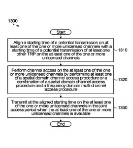
[2] The present application relates to mobile air interface technologies,
in particular to
methods and systems for access to unlicensed spectrum by transmit receive
points (TRPs).
BACKGROUND
[3] There is ongoing interest in increasing the use of unlicensed spectrum.
There is
special interest in aggregating unlicensed spectrum to licensed spectrum, in
order to increase
resources of a network when needed. Licensed assisted access ("LAA") allows
access to
unlicensed spectrum via unlicensed component carrier, with assistance from
primary
component carriers (PCC) operating on licensed spectrum. LAA aims to port the
Mobile
Broadband (MBB) air interface to the unlicensed spectrum through aggregating
unlicensed
component carriers (CCs) at the operator's small cells. Small cells (also
referred to as low
power nodes (LPNs)) are low-powered radio access nodes that may operate in
both the
licensed and unlicensed spectrum, and have a relatively short coverage range
(e.g., within
200m from antenna(s) of the small cell). The 5 GHz unlicensed spectrum,
commonly used by
wireless local area networks (WLANs), is of particular interest.
[4] Some existing technologies transmit a blocking signal or use a
deferring time period
between a clear channel assessment (CCA) process completing time and a
downlink
transmission starting time, and unlicensed spectrum is not used for downlink
transmission
during this period. As well, other TRPs of WLAN or other LAA groups may start
downlink
transmission during the deferring time period and thus cause downlink
transmission collisions.
In addition, some existing technologies have aggressive schemes to access
unlicensed
spectrum.
[5] LAA is directed to individual TRPs accessing one or more channels and
does not
support spatial reuse.
[6] It is important for a technology to access unlicensed spectrum in a
fair and efficient
manner, so that satisfactory intra-operator or inter-operators coexistence
1
Date Recue/Date Received 2022-03-25
CA 03103057 2020-12-08
WO 2019/238021 PCT/CN2019/090622
performance as well as satisfactory coexistence performance with incumbent
WLAN may be
achieved. With the envisioned dense deployments and/or high channel occupancy
of WLAN,
e.g., IEEE802.11ac, and LAA networks, it is more challenging to attain
coexistence fairness.
New Radio Unlicensed (NR-U) networks are being developed in part to address
such
concerns.
SUM MARY
[7] The present disclosure describes methods and systems for access to
unlicensed
spectrum by a group of transmit receive points (TRPs). A group of TRPs can
include any of
a group of base stations (for example gNBs) that are spatially distributed
with ideal or non-
ideal backhaul/fronthaul connections, a group of antenna panels of the same
gNB (intra-site
panels) or a group of antennas with different QCL (quasi co-located)
assumptions, i.e., with
different large-scale channel parameters. Therefore, an individual TRP may be
a gNB, a
radio head, an antenna set of a gNB or one of multiple antenna sets with
different QCL
assumptions.
[8] An objective of embodiments of the present disclosure is to access
unlicensed
spectrum in an efficient manner. In embodiments of the present application,
optional
objectives may also include to avoid downlink transmission collisions, and, to
improve
coexistence fairness with other radio access technologies, and enable advanced
transmission schemes such as coordinated multi-point transmission (CoMP) in
the
unlicensed spectrum.
[9] According to an aspect of the present application there is provided a
method for a
transmit receive point (TRP) to access one or more unlicensed channels in an
unlicensed
spectrum jointly with at least one other TRP. the method includes: aligning a
starting time of
a potential transmission on at least one of the one or more unlicensed
channels with a
starting time of a potential transmission of at least one other TRP on the at
least one of the
one or more unlicensed channels; performing channel access on the at least one
of the one
or more unlicensed channels by performing at least one of a spatial domain
channel access
procedure or a combination of a spatial domain channel access procedure and a
frequency
domain multi-channel access procedure; and transmitting at the aligned
starting time on the
at least one of the one or more unlicensed channels in the joint access period
when the at
least one of the one or more unlicensed channels is available.
[10] In some embodiments, the method further includes receiving a
configuration from
a central controller including an indication of a type of a spatial domain
channel access
procedure and a type of a frequency domain multi-channel access procedure to
be used for
joint access to the one or more unlicensed channels.
2
CA 03103057 2020-12-08
WO 2019/238021
PCT/CN2019/090622
[11] In some embodiments, performing channel access includes
performing a first
type of clear channel assessment (CCA) for at least one of the one or more
unlicensed
channels by configuring the TRP with a random back-off counter for at least
one unlicensed
channel for the first type of CCA.
[12] In some embodiments, configuring the TRP with a random back-off
counter for at
least one unlicensed channel for a first type of CCA includes configuring the
TRP with a
different random back-off counter for one of the unlicensed channels than a
random back-off
counter for one of the unlicensed channels for the at least one other TRP.
[13] In some embodiments, configuring the TRP with a random back-off
counter for at
least one unlicensed channel for a first type of CCA includes configuring the
TRP with the
same random back-off counter for one of the unlicensed channels as a random
back-off
counter for one of the unlicensed channels for the at least one other TRP.
[14] In some embodiments, the random back-off counter is generated from a
single
distribution for a contention window based at least in part on the channel
access priority
class.
[15] In some embodiments, the random back-off counter is generated from a
distribution for a contention window corresponding to a largest channel access
priority class
value of all of the unlicensed channels across the set of the TRP and the at
least one other
TRP.
[16] In some embodiments, configuring the TRP with a random back-off
counter for at
least one unlicensed channel for a first type of CCA includes configuring the
TRP with a
random back-off counter for all of the unlicensed channels that is different
than a random
back-off counter for all of the unlicensed channels for the at least one other
TRP.
[17] In some embodiments, configuring the TRP with a random back-off
counter for at
least one unlicensed channel for a first type of CCA includes configuring the
TRP with a
random back-off counter for all of the unlicensed channels that is that same
as a random
back-off counter for all of the unlicensed channels for the at least one other
TRP.
[18] In some embodiments, performing the first type of CCA for at least one
of the one
or more unlicensed channels includes performing a wideband (WB) CCA for all of
the
unlicensed channel simultaneously.
[19] In some embodiments, the method further includes, upon the TRP
determining
that the WB channel is busy during a CCA slot of the WB CCA, changing from the
WB CCA
3
CA 03103057 2020-12-08
WO 2019/238021
PCT/CN2019/090622
to sub-band CCA for the remaining CCA slots without terminating the channel
access
procedure for each separate unlicensed channel.
[20] In some embodiments, determining that the WB channel is busy
during a CCA
slot of the WB CCA comprises receipt of a notification of CCA failure.
[21] In some embodiments, the method further includes the TRP performing a
second
type of CCA for at least one of the one or more unlicensed channels
immediately prior to the
starting time of the potential transmission on the one or more of the
unlicensed channels.
[22] In some embodiments, the method further includes, when the first type
of CCR, or
the second type of CCA senses an unlicensed channel to be busy during a CCA
slot, the
TRP sending a notification of at least one of a CCA failure and a missed
starting time of a
potential transmission to the at least one other TRP.
[23] In some embodiments, the method further includes receiving a
notification of an
earlier starting time of a potential transmission than a previously scheduled
starting time of a
potential transmission and realigning the starting time of the potential
transmission
accordingly.
[24] In some embodiments, a duration between an end of the first type of
CCA and
the starting time of a potential transmission are defined by at least one of a
self-deferral
duration, a post-back-off CCA and a duration of a second type of CCA.
[25] According to an aspect of the present application there is provided a
transmit
receive point (TRP) comprising at least one antenna configured to transmit or
receive a
signal and a controller. The controller is configured to: align a starting
time of a potential
transmission on at least one of the one or more unlicensed channels with a
starting time of a
potential transmission of at least one other TRP on the at least one of the
one or more
unlicensed channels; perform channel access on the at least one of the one or
more
unlicensed channels by performing at least one of a spatial domain channel
access
procedure or a combination of a spatial domain channel access procedure and a
frequency
domain multi-channel access procedure; and transmit at the aligned starting
time on the at
least one of the one or more unlicensed channels in the joint access period
when the at least
one of the one or more unlicensed channels is available.
[26] In some embodiments, the TRP is further configured to receive on the
at least
one antenna, a configuration from a central controller including an indication
of a type of a
spatial domain channel access procedure and a type of a frequency domain multi-
channel
access procedure to be used for joint access to the one or more unlicensed
channels.
4
CA 03103057 2020-12-08
WO 2019/238021
PCT/CN2019/090622
[27] In some embodiments, the controller configured to perform channel
access
comprises the controller performing a first type of clear channel assessment
(CCA) for at
least one of the one or more unlicensed channels by configuring the TRP with a
random
back-off counter for at least one unlicensed channel for the first type of
CCA.
[28] In some embodiments, the controller configuring the TRP with a random
back-off
counter for at least one unlicensed channel for a first type of CCA includes
configuring the
TRP with a different random back-off counter for one of the unlicensed
channels than a
random back-off counter for one of the unlicensed channels for the at least
one other TRP.
[29] In some embodiments, the controller configuring the TRP with a random
back-off
counter for at least one unlicensed channel for a first type of CCA includes
configuring the
TRP with the same random back-off counter for one of the unlicensed channels
as a random
back-off counter for one of the unlicensed channels for the at least one other
TRP.
[30] In some embodiments, the controller performing the first type of CCA
for at least
one of the one or more unlicensed channels includes performing a wideband (WB)
CCA for
all of the unlicensed channel simultaneously.
[31] In some embodiments, the controller is further configured to, upon the
TRP
determining that the WB channel is busy during a CCA slot of the WB CCA,
change from the
WB CCA to sub-band CCA for the remaining CCA slots without terminating the
channel
access procedure for each separate unlicensed channel.
[32] In some embodiments, the controller is further configured to perform a
second
type of CCA for at least one of the one or more unlicensed channels
immediately prior to the
starting time of the potential transmission on the one or more of the
unlicensed channels.
[33] In some embodiments, when the first type of CCA or the second type of
CCA
senses an unlicensed channel to be busy during a CCP, slot, the TRP sends a
notification of
at least one of a CCA failure and a missed starting time of a potential
transmission to the at
least one other TRP.
BRIEF DESCRIPTION OF THE DRAWINGS
[34] Reference will now be made, by way of example, to the accompanying
drawings
which show example embodiments of the present application, and in which:
[35] FIG. 1 is a block diagram illustrating an example communications
system in
accordance with one implementation of the present disclosure;
[36] FIG. 2 is a block diagram illustrating an example processing
system in
accordance with one implementation of the present disclosure;
5
CA 03103057 2020-12-08
WO 2019/238021
PCT/CN2019/090622
[37] FIG. 3A is a diagram illustrating a mechanism for access to unlicensed
spectrum
by a single New Radio Unlicensed (NR-U) gNB;
[38] FIG. 3B is a diagram illustrating a mechanism for access to unlicensed
spectrum
by a group of NR-U gNBs;
[39] FIG. 4 is a diagram illustrating an example for a group of TRPs
attempting to
jointly access a single channel in unlicensed spectrum according to one
embodiment of the
present disclosure;
[40] FIG. 5 is a diagram illustrating a second example for a group of TRPs
attempting
to jointly accessing a single channel in unlicensed spectrum according to one
embodiment of
the present disclosure;
[41] FIG. 6A is a diagram illustrating a third example for a group of TRPs
attempting
to jointly accessing a single channel in unlicensed spectrum according to one
embodiment of
the present disclosure;
[42] FIG. 6B is a diagram illustrating a fourth example for a group of TRPs
attempting
to jointly accessing a single channel in unlicensed spectrum according to one
embodiment of
the present disclosure;
[43] FIG. 7A is a diagram illustrating a fifth example for a group of TRPs
attempting to
jointly accessing a single channel in unlicensed spectrum according to one
embodiment of
the present disclosure;
[44] FIG. 7B is a diagram illustrating a sixth example for a group of TRPs
attempting
to jointly accessing a single channel in unlicensed spectrum according to one
embodiment of
the present disclosure;
[45] FIG. 8A is a diagram illustrating a seventh example for a group of
TRPs
attempting to jointly accessing a single channel in unlicensed spectrum
according to one
embodiment of the present disclosure;
[46] FIG. 8B is a diagram illustrating an eighth example for a group of
TRPs
attempting to jointly accessing a single channel in unlicensed spectrum
according to one
embodiment of the present disclosure;
[47] FIG. 9A is a diagram illustrating a first example for a group of TRPs
attempting to
jointly accessing a multiple channels in unlicensed spectrum according to one
embodiment
of the present disclosure;
6
CA 03103057 2020-12-08
WO 2019/238021
PCT/CN2019/090622
[48] FIG. 9B is a diagram illustrating a second example for a group of TRPs
attempting to jointly accessing a multiple channels in unlicensed spectrum
according to one
embodiment of the present disclosure;
[49] FIG. 10A is a diagram illustrating a third example for a group of TRPs
attempting
to jointly accessing a multiple channels in unlicensed spectrum according to
one
embodiment of the present disclosure;
[50] FIG. 10B is a diagram illustrating a fourth example for a group of
TRPs
attempting to jointly accessing a multiple channels in unlicensed spectrum
according to one
embodiment of the present disclosure;
[51] FIG. 10C is a diagram illustrating a fifth example for a group of TRPs
attempting
to jointly accessing a multiple channels in unlicensed spectrum according to
one
embodiment of the present disclosure;
[52] FIG. 11A is a diagram illustrating a sixth example for a group of TRPs
attempting
to jointly accessing a multiple channels in unlicensed spectrum according to
one
.. embodiment of the present disclosure;
[53] FIG. 11B is a diagram illustrating a seventh example for a group of
TRPs
attempting to jointly accessing a multiple channels in unlicensed spectrum
according to one
embodiment of the present disclosure; and
[54] FIG. 12 is a diagram illustrating an eighth example for a group of
TRPs
attempting to synchronously access a single channel while jointly accessing
multiple
channels in unlicensed spectrum according to one embodiment of the present
disclosure.
[55] FIG. 13 is a flow chart describing a method according to a first
aspect of the
application.
[56] FIG. 14 is a flow chart describing a method according to a second
aspect of the
.. application.
[57] FIG. 15 is a flow chart describing a method according to a third
aspect of the
application.
[58] Similar reference numerals may have been used in deferent figures to
denote
similar components. Although aspects of the invention will be described in
conjunction with
the illustrated embodiments, it will be understood that it is not intended to
limit the invention
to such embodiments.
7
CA 03103057 2020-12-08
WO 2019/238021 PCT/CN2019/090622
DETAILED DESCRIPTION OF ILLUSTRATIVE EMBODIMENTS
[59] The present disclosure teaches methods and systems for accessing the
unlicensed spectrum. Although described below primarily with respect to New
Radio
Unlicensed (NR-U) networks, the present disclosure may also be applied to
other networks
operating on unlicensed spectrum.
[60] Listen-Before-Talk (LBT) mechanism may be used for access to
unlicensed
spectrum. A TRP may access a medium (which in the case of this application is
unlicensed
spectrum) to transmit its downlink transmission, such as a downlink burst
during a channel
occupancy time (COT), when the medium is sensed by the TRP to be available or
idle for a
predefined period. Such a period may be a clear channel assessment (CCA)
period. A
downlink transmission, such as a downlink COT, may include downlink user data
and/or
control signaling. A downlink COT may further include UL data and/or control
signaling
occurring after a DL-to-UL switching time gap.
[61] The LBT mechanism specified for LAP, (Release 13 to 15 of 3GPP
standard)
relies only on energy detection (ED) to determine the availability of the
medium and it is
considered the baseline for designing the channel access mechanism for NR-U.
If the same
ED threshold is used, this LBT mechanism is more aggressive than the carrier
sense
multiple access with collision avoidance (CSMA/CA) mechanism currently used by
WLAN.
This is because the CSMA/CA mechanism used by WLAN can be 20dB more sensitive
in
detecting the presence of other WLAN signals through Physical Carrier sense
and MAC
(virtual) Carrier sense.
[62] As well, joint access by NR-U TRPs is desired to simplify NR-U
interference
measurement and management. In particular, joint access by NR-U TRPs may help
address an intra-NR-U operator "exposed node" problem that may result in
improved
spectral efficiency. The "exposed node" problem occurs when for two
neighboring NR-U
TRPs operating independently, although not interfering with each other, one
may
nonetheless block the other's access to the medium. When two TRPs are not
interfering with
each other's transmission, their respective served UEs are outside the
overlapping coverage
area. The medium may be the unlicensed spectrum, an unlicensed spectrum
channel, or a
set of unlicensed spectrum channels. The other TRP may perceive that the
medium is busy
when it senses the presence of a transmission of the one TRP on the medium.
When the
medium is perceived as busy by a TRP, the TRP considers that the medium is
unavailable at
its scheduled downlink transmission starting time. When the two TRPs are
grouped together,
such as in the same group or Radio Access Cluster (RAC), the TRPs may jointly
access the
medium as one group. The group of the TRPs can access the medium at the same
starting
8
time, i.e., synchronously. A first TRP will not block access to the medium by
the second TRP
because the second TRP has already started transmitting over the medium.
[63] Joint access by NR-U TRPs may also provide more effective
protection from co-
channel interference that occurs due to a "hidden node" co-channel
interference problem. The
"hidden node" problem occurs where a node within the coverage area of a first
NR-U TRP may
not be in the coverage area of a neighboring second NR-U TRP. However, the
node may still
interfere with transmissions by the second TRP. By grouping the first and
second TRPs
together as a single group or RAC, transmissions from the first TRP may block
the channel
access of the node and thus protect the transmission of the first TRP.
[64] Joint access of neighboring TRPs may also enable features such as
aligning the
transmissions of neighboring TRPs so as to enable more airtime for coexisting
nodes and hence
improving coexistence fairness, enabling advanced transmission schemes such as
Coordinated
Multi-Point (CoMP).
[65] FIG. 1 illustrates an example system 100 in which examples described
herein may
be implemented. The system 100 may be used in an NR-U network.
[66] In the example system 100, a controller manages operation of a
plurality of TRP
groups, such as RACs, for example, TRP groups 140, 150, and 160. In an
embodiment, the
controller may be a central spectrum management control unit (CSMC) 102. A
CSMC 102 is a
network logical controller, which may be hosted by a Macro gNB or a TRP
connected to the
TRPs of a group. The CSMC 102 may define one or more RACs for the TRPs managed
by the
CSMC 102. Each RAC may be channel-specific or channel set-specific ¨ that is,
each RAC
may be defined to use an unlicensed spectrum channel or a set of unlicensed
channels that is
different from an adjacent RAC. Several examples of mechanisms to group TRPs
into disjoint
groups or RACs are described in US application No. 14/869,617.
[67] Each group or RAC may include one or more TRPs and each TRP may belong
to
one or more groups or RACs. For example, TRP 108 in FIG. 1 belongs to both
group 140 and
group 150. Each TRP provides unlicensed spectrum access for one or more
devices, such as
UEs or STAs. A TRP may also be a gNB. In the example of FIG. 1, TRP group 140
may
comprise TRP1 104, TRP2 106, and TRP3 108; TRP group 150 may comprise TRP3 108
and
TRP6 110; and TRP group 160 may comprise TRP4 112 and TRP5 114.
[68] Each TRP of a TRP group may connect to the CSMC 102 via at least
one
communication link, for example, a backhaul connection link, such as backhaul
connection links
124, 126, 128, 130, 132, or 134. Message between the TRPs and the CSMC 102 may
9
Date Recue/Date Received 2022-03-25
CA 03103057 2020-12-08
WO 2019/238021 PCT/CN2019/090622
be exchanged via communication links. The communication links may be wireless
communication link, such as microwave links, or wired links, such as optical
fiber links. The
CSMC 102 may manage the TRPs via one or more communication links.
[69] Joint access of TRPs, including NR-U TRPs, is desired to
opportunistically
achieve a frequency reuse factor of one. As shown in TRP groups 140, 150 and
160, TRP
group 140 may use unlicensed spectrum channel 1, TRP group 150 may use
unlicensed
spectrum channel 2, and TRP group 160, the coverage area of which does not
overlap with
that of the TRP group 140, may re-use unlicensed spectrum channel 1. Grouping
TRPs into
a group allows the same unlicensed channel to be used by all of the TRPs of
the TRP group.
As such, a frequency reuse factor of one of the TRPs within a TRP group may be
achieved.
With respect to a TRP belonging to more than one TRP groups, the TRP uses the
unlicensed spectrum channel assigned to the specific TRP group when the TRP
operates as
a member of the TRP group. For example, when TRP3 108 of FIG. 1 operates as a
member
TRP of TRP group 140, TRP3 108 uses the unlicensed channel assigned to TRP
group 140,
namely, the unlicensed channel 1; and when TRP 108 operates as a member TRP of
TRP
group 150, TRP3 108 uses the unlicensed spectrum channel assigned to group
150, namely,
the unlicensed spectrum channel 2.
[70] Although FIG. 1 only illustrates one CSMC 102, multiple CSMCs may be
used to
manage a plurality of TRPs. The CSMCs may be interconnected via backhaul
connection
links or interfaces, such as X2 or 5G Xn. As well, the numbers of TRPs of each
TRP group
managed by the CSMC 102 may also be varied.
[71] FIG. 2 is a block diagram of an example processing system 200, which
may be
used to implement the methods and systems disclosed herein. The processing
system 200
may be a component of a CSMC, a gNB, or a TRP. Other processing systems
suitable for
implementing the present disclosure may also be used, which may include
components
differing from those discussed below. Although FIG. 2 shows a single instance
of each
component, there may be multiple instances of each component in the processing
system
200.
[72] The processing system 200 may include one or more processing devices
205,
such as a processor, a microprocessor, an application-specific integrated
circuit (ASIC), a
field-programmable gate array (FPGA), a dedicated logic circuitry, or
combinations thereof.
The processing system 200 may also include one or more input/output (I/O)
interfaces 210,
which may enable interfacing with one or more appropriate input devices 235
and/or output
devices 240. The processing system 200 may include one or more network
interfaces 215
for wired or wireless communication with a network (e.g., a wireless core
network, an
CA 03103057 2020-12-08
WO 2019/238021
PCT/CN2019/090622
intranet, the Internet, a P2P network, a WAN and/or a LAN). The network
interface(s) 215
may include wired links (e.g., Ethernet cable, or fiber optical links) and/or
wireless links (e.g.,
one or more microwave links, or satellite links) for intra-network and/or
inter-network
communications. The network interface(s) 215 may provide wireless
communication via one
.. or more transmitters or transmitting antennas and one or more receivers or
receiving
antennas, for example. The processing system 200 may also include one or more
storage
units 220, which may include a mass storage unit such as a solid state drive,
a hard disk
drive, a magnetic disk drive and/or an optical disk drive.
[73] The processing system 200 may include one or more memories 225, which
may
include a volatile or non-volatile memory (e.g., a flash memory, a random
access memory
(RAM), and/or a read-only memory (ROM)). The non-transitory memory(ies) 225
may store
instructions for execution by the processing device(s) 205, such as to carry
out examples
described herein. The memory(ies) 225 may include other software instructions,
such as for
implementing an operating system and other applications/functions. In some
examples, one
.. or more data sets and/or module(s) may be provided by an external memory
(e.g., an
external drive in wired or wireless communication with the processing system
200) or may
be provided by a transitory or non-transitory computer-readable medium.
Examples of non-
transitory computer readable media include a RAM, a ROM, an erasable
programmable
ROM (EPROM), an electrically erasable programmable ROM (EEPROM), a flash
memory, a
.. CD-ROM, or other portable memory storage.
[74] There may be a bus 230 providing communication among components of the
processing system 200, including the processing device(s) 205, I/O
interface(s) 210, network
interface(s) 215, storage unit(s) 220 and/or memory(ies) 225. The bus 230 may
be any
suitable bus architecture including, for example, a memory bus, a peripheral
bus or a video
.. bus.
[75] In FIG. 2, the input device(s) 235 (e.g., a keyboard, a mouse, a
microphone, a
touchscreen, and/or a keypad) and output device(s) 240 (e.g., a display, a
speaker and/or a
printer) are shown as external to the processing system 200. In other
examples, one or more
of the input device(s) 235 and/or the output device(s) 240 may be included as
a component
of the processing system 200.
[76] FIG. 3A illustrates a category 4 (CAT4) LBT mechanism for a single NR-
U gNB to
access a medium. In FIG. 3A, a TRP group is associated with a CSMC 302, and an
NR-U
gNB1 304. The CSMC 302 is connected to the gNB1 304 via a backhaul connection
link.
The gNB1 304 may provide unlicensed spectrum access to NR-U UE1 and NR-U UE2.
The
horizontal axis of the plot in FIG. 3A is divided into marked intervals
labeled from 1 to 8. The
11
CA 03103057 2020-12-08
WO 2019/238021
PCT/CN2019/090622
marked intervals are the boundaries of a particular time unit. The time unit
may be a slot, a
mini-slot or a sub-frame boundary. The boundaries may also align with
boundaries of time
units of the licensed spectrum. In this example, the gNB1 304 first senses,
for example using
energy detection (ED)-based CCA, that the medium is busy at period 312 that
occurs over a
portion of interval 1, all of interval 2 and a portion of interval 3. The CCA
process includes a
Distributed Coordination Function (DCF) InterFrame Space (DIES) 314 within
interval 3 and
a random Contention Window (CW) duration 316 that occurs over a portion of
interval 3, all
of interval 4 and a portion of interval 5. The CW 316 is also called an
extended Clear
Channel Assessment (eCCA) process. The gNB1 304 independently generates a
random
back-off counter value, CW, which corresponds with the CW 316, where CW=CWp X
a CCA
slot duration. For example, a CCA slot duration may be 9 ps. When the status
of the
medium is continuously idle for a DIES duration 314, for example 34 ps, the
gNB1 304
continues sensing the medium during the CW 316. When the NR-U gNB1 304 is
sensing
the medium during CW 316, the back-off counter value initialized with CWp
decrements by 1
when an idle CCA slot duration has elapsed, and is decreased to 0 at the
completing time of
CW 316. In FIG. 3A, the medium remains idle at the completing time of the CW
316.
Release 13 of 3GPP requires LAA TRPs to align their respective downlink burst
transmissions during COTs with a starting time of a licensed primary component
carrier
subframe, or a licensed spectrum subframe, for example the licensed subframe
starting time.
However, for NR-U, there is no such requirement of aligning the transmission
with a starting
time of the licensed primary component carrier subframe. The CSMC 302
determines the
downlink burst transmission starting time 320 and communicates the starting
time 320 to
NR-U gNB1 304 via the backhaul connection link, so that NR-U gNB1 304 may
access to the
medium at the starting time 320. At the starting time 320, which aligns with a
starting time
of the licensed primary component carrier subframe, gNB1 304 starts
transmitting over the
medium its downlink bursts to NR-U UE1 and/or NR-U UE2 during the duration of
322.
[77] If
during the CW 316, the eCCA process is terminated due to the medium 'busy'
assessment, the remaining back-off counter value is frozen to maintain
priority in a
subsequent medium access attempt of the NR-U gNB1 304. In a particular
example, the
CWp value initially generated by the random back-off counter generator of the
NR-U gNB1
304 is equal to 5 CCA slot durations, during the CW 316. If the medium becomes
busy when
the back-off counter value is currently equal to 3 CCA slot durations (i.e.
after the counter
has been decremented by 2 successful CCA slots), the random back-off counter
of the NR-U
gNB1 304 is frozen at 3 CCA slot durations. In a subsequent medium access
attempt by
NR-U gNB1 304, the random back-off counter generator will not generate a new
counter
value but use the remaining value of 3 CCA slot durations.
12
CA 03103057 2020-12-08
WO 2019/238021
PCT/CN2019/090622
[78] FIG. 3B illustrates a CAT4 LBT mechanism for a group of NR-U gNBs to
jointly
access a medium. In the example of FIG. 3B, a TRP group is associated with a
CSMC 306,
an NR-U gNB1 308 and an NR-U gNB2 310. The CSMC 306 is connected to each of NR-
U
gNB1 308 and NR-U gNB2 310 via a backhaul connection link. The NR-U gNB1 308
may
provide unlicensed spectrum access to NR-U UE1 and NR-U UE2. The NR-U gNB1 310
may provide unlicensed spectrum access to NR-U UE3. In FIG. 3B, the NR-U gNB1
308
and NR-U gNB2 310 may first sense, for example using ED-based CCA, that the
medium is
busy at periods 332 and 342, respectively. The NR-U gNB1 308 and NR-U gNB2 310
keep
sensing the medium. The NR-U gNB1 308 and NR-U gNB2 310 independently generate
respective random back-off counter values CW1 and CW2, which corresponds with
CW1
336 and CW2 346, respectively, where CW1= cws1 X a CCA slot duration and CW2=
cws2
X a CCA slot duration. For example, a CCA slot duration may be 9 ps. When the
status of
the medium is continuously idle for a DIFS duration 334 or 344, NR-U gNB1 308
and NR-U
eNB2 310 continue sensing the medium during the CW 336 and CW 346. When the NR-
U
gNB1 308 and NR-U gNB2 310 are sensing the medium during respective CW1 336
and
CW2 346, the respective back-off counter values cws1 and cw52 decrement by 1
when a
CCA slot duration has elapsed, and are decreased to 0 at the completing time
of OW 336 or
OW 346, respectively. Similarly, if during the CW1 336 or 0W2 346, the CCA
process is
terminated due to the medium 'busy' assessment, the remaining back-off counter
value cws1
or cw2 is frozen to maintain priority in a subsequent medium access attempt of
the NR-U
gNB1 308 or NR-U gNB2 310.
[79] CW1 336 and CW2 346 may differ from each other. In the example of FIG.
3B,
CW1 336 is shorter than 0W2 346. The NR-U gNB1 308 and NR-U gNB2 310
continuously
assess whether the medium is idle during CW1 336 and CW2 346, respectively,
using ED-
based CCA. NR-U gNB1 308 can align its downlink burst transmissions with a
starting time
of a licensed primary component carrier subframe at 321, which occurs after
both the CW1
period 336 and CW2 period 346 have completed. Therefore, after the completion
of a
successful CCA period, each of the NR-U gNB1 308 and the NR-U gNB2 310 defers
its
downlink burst transmission to a common starting time 321, so that gNB1 308
and gNB2 310
may jointly access the medium at the common downlink subframe transmission
starting time
321. The CSMC 306 determines the common starting time 321 and communicates the
common starting time 321 to the NR-U gNB1 308 and NR-U gNB2 310 via respective
backhaul connection links. After the CCA process has been successfully
completed but
before the starting time 321, NR-U gNB1 308 invokes a deferring time period
338 for aligning
its downlink burst transmission to the starting time 321. Similarly, NR-U gNB2
310 invokes a
deferring time period 348 for aligning its transmission of bursts starting at
the starting time
13
CA 03103057 2020-12-08
WO 2019/238021
PCT/CN2019/090622
321. As such, the NR-U gNB1 308 and NR-U gNB2 310 may jointly access the
medium at
the common starting time 321.
[80] Similar to the example of the NR-U gNB1 304 in FIG. 3A, during the CW1
336 or
CVV2 346 period in FIG. 3B, if an eCCA is terminated due to 'busy' assessment,
the
remaining back-off counter value cws1 of NR-U gNB1 308 or cws2 of NR-U gNB2
310 is
frozen to maintain the priority in a subsequent access attempt.
[81] During the deferring time periods 338 and 348, neither the NR-U gNB1
308 nor
the NR-U gNB2 310 transmits any signal to notify adjacent TRPs of other
networks that the
NR-U gNB1 308 or the NR-U gNB2 310 has completed a CCA process. As such, the
medium appears to remain idle to TRPs of other networks, such as WLAN or other
NR-U
networks. Just prior to the end of the deferring time periods 338 and 348 a
Category 2
(CAT2) CCA 339,349 can be performed to determine if the channel is still
accessible. The
CAT2 CCA is a brief one shot CCA that would end at the target start time for
accessing the
channel. After the deferring time periods 338 and 348, if the CAT2 CCA are
successful, the
NR-U gNB1 308 and NR-U gNB2 310 start transmitting respective downlink bursts
in COTs
to NR-U UEs at the common starting time 321 for the durations of 340 and 350,
respectively.
[82] In the example of FIG. 3A, the NR-U gNB1 304 transmits a blocking
signal 318
on the medium to prevents TRPs of WLAN or other NR-U groups from accessing the
medium. However, in the group access mechanism of FIG. 3B, the NR-U gNB1 308
or the
NR-U gNB2 310 in FIG. 3B cannot transmit a blank blocking or reservation
signal to prevent
TRPs of WLANs or other NR-U groups from accessing the medium during the
deferring time
period 338 or 348. In FIG. 3B, after the NR-U gNB1 308 has completed its CCA
process
before the CCA process of the NR-U gNB2 310 is completed, if NR-U gNB1 308
starts
transmitting a blocking signal on the medium, if the NR-U gNB2 310 senses the
blocking
signal, the NR-U gNB2 310 may determine that the medium became "busy" and
subsequently terminate its eCCA process. Therefore, the blocking signal may
defeat joint
access to the medium by a group of TRPs.
[83] On the other hand, because during the deferring time periods 338 and
348, the
status of the medium is still idle, adjacent TRPs of WLAN or other NR-U groups
that have
completed their CCA process before the common starting time 321 may access the
medium.
In other words, during deferring time periods 338 and 348, the status of the
medium may
change from idle to busy. The access of the medium by adjacent TRPs of WLAN or
other
NR-U groups prior to the starting time 321 will not cause the NR-U gNB1 308
and the NR-U
gNB2 310 to back off from downlink burst transmissions in COTs at the common
starting
time 321. As such, when the NR-U gNB1 308 and the NR-U gNB2 310 start
transmitting
14
CA 03103057 2020-12-08
WO 2019/238021 PCT/CN2019/090622
bursts in COT on the downlink of the medium at the common starting time 321,
their
downlink bursts transmissions in COTs could collide with the transmissions of
adjacent
TRPs of WLAN or other NR-U groups. This collision may cause back-off delays
and
throughput losses to other co-existing networks, especially WLANs.
[84] Other versions of CCP, may be used as opposed to, or in addition to,
the CAT4
CCA. A CAT2 CCA involves a brief one-shot CCA for pre-defined deterministic
duration, e.g.,
25 or 34 sec, just prior to a scheduled t
-target time for accessing a channel for either downlink
or uplink. The CAT2 CCA may be used in addition to the CAT4 CCA. For instance,
the CAT4
CCA may occur for a period of time, followed by a self-deferral period between
the CAT4
CCA and the t
-target time. To determine if there is any new transmission on the channel
since
the end of the CAT4 CCA, or if transmission on the channel determined during
the CAT4
CCA has dissipated, a CAT2 CCA occurs just before the t
-target time as a final check to
determine if the channel is accessible or not. Another type of CCA is a
wideband (WB) CCA.
Although the CAT4 CCA and CAT2 CCA are originally defined for single channel
CCA, the
WB CCA extends the CCA concept to allow a TRP to make a determination of the
collective
state of multiple contiguous channels simultaneously. In some embodiments of
the present
disclosure, if there is a determination that a WB channel state is busy, then
the WB CCA can
be switched, e.g., during the back-off duration CCA, to multiple sub-band
CCAs. The sub-
band CCAs are performed similar to the original CAT4 CCA or CAT2 CCA.
[85] LAA-specified channel access procedures for transmission(s) on
multiple carriers
for a single TRP are performed according to one of Type A or Type B procedures
as defined
in 3GPP TS 36.213 Section 15.1.5. A TRP can access multiple component carriers
(CCs), or
channels, on which NR-U secondary cell (Scell) transmissions are performed,
according to
the Type A or Type B procedures. In LAA, each CC is a 20MHz unlicensed
channel. In NR-U,
a CC may comprise multiple channels. However, a similar frequency-domain type
A-like and
type B-like procedure can be applied within one CC.
[86] Type A has two variations for generation of multiple back-off
counters of a group
of CCs accessible to the TRP. In a first variation, referred to as Type Al,
back-off counters
used for each CC of the group are generated and maintained independently from
different
distributions, i.e., using independent values of the priority contention
window CWp. The term
distribution refers to a particular range of values that the back-off counter
can be randomly
selected from. In a second variation, referred to as Type A2, the back-off
counters for each
CC of the group are set to a same number generated from a distribution of a
largest priority
contention window CW0 of the group of CCs.
CA 03103057 2020-12-08
WO 2019/238021 PCT/CN2019/090622
[87] For Type B, a single CC of multiple CCs potentially being
accessed is selected as
a primary channel for which the TRP performs a CAT4 CCA process, and the
remainder of a
group of multiple CCs are designated as secondary channels. If the CAT4 CCA is
successful
for the primary CC, then the secondary CCs may have a shorter one-shot CCA
process
performed on them, such as a CAT2 CCA, immediately before the TRP may access
the
primary and secondary CCs. If the TRP needs to apply self-deferral after a
successful
backoff of the CAT4 CCA, a one-shot CCA process may be performed as well on
the
primary CC before the TRP may access the primary and secondary CCs. Type B
also has
two variations for generation of a back-off counter for a randomly selected
primary CC from
the group of CCs accessible to the TRP. In a first variation, referred to as
Type Bl, the back-
off counter for the selected primary CC is generated from a single common
distribution with
a common CWp, regardless of the actual value of the CWp of the selected
primary CC. In a
second variation, referred to as Type B2, the back-off counter for the
selected primary CC is
set to a number generated from a distribution of a largest CWp across the set
of CCs.
[88] Reference is made to joint access by multiple TRPs in the description
below. It is
to be understood that although a majority of the examples are described with
regard to joint
multiple access TRPs, the same principles can apply to multiple antenna panels
of a single
TRP or multiple antenna panels on each of multiple TRPs being used for joint
access.
[89] Aspects of the present disclosure may provide joint TRP access to
multiple
channels in a manner that is compliant with existing aspects of New Radio
(NR). This may
be achieved through combining either a spatial-domain Type A-like or Type B-
like procedure,
and either a frequency-domain Type A-like or Type B-like multi-channel access
procedure.
In such a joint TRP mechanism, one or more of the following techniques may
also be utilized.
A `CCA Failure' occurs when a TRP detects a signal on the channel and
therefore the
channel is considered to be unavailable. A 'Missed Target' occurs when a TRP
determines it
will not be able to complete its back-off procedure before an arranged target
start time. A
TRP `CCA Failure' or 'Missed Target' indication that is triggered by either
respective event
may be transmitted to a controller to be used to improve efficiencies of
operation of the joint
access process by the other TRPs of the group. For example, the indications
may enable an
earlier (fall-back) alignment of a transmission start time than a previous
target start time, if
the previous start time was dependent upon the TRP experiencing the `CCA
Failure' or
'Missed Target'. Another technique may include switching from performing a
Wdeband (WB)
CCA simultaneously on multiple channels to performing individual sub-band CCAs
during a
same channel access attempt to avoid inadvertently identifying that all of a
group of
channels for which the WB CCA is performed are unavailable if less than all of
the channels
16
CA 03103057 2020-12-08
WO 2019/238021 PCT/CN2019/090622
would trigger a "CAA Failure" using individual sub-band CCAs. Another
technique may
include using TRP on-demand blanking within an acquired Channel Occupancy Time
(COT),
i.e. the portion of the time domain resource of a given channel accessible to
transmission, to
allow TRPs to have additional opportunities within the COT for late joint
access of TRPs. A
CCA Success' occurs when a TRP does not detect a threshold level of energy on
the
channel and therefore the channel is considered to be available for
transmission or reception
by the TRP. A TRP 'CCP, Success' indication sent by a TRP may enable alignment
of
transmissions when using CAT2 CCA for spatial domain secondary TRPs. DL and UL
slot
configurations and dynamic indications associated with those slot
configurations can be
aligned across the jointly acquired COTs. Selecting a spatial-domain primary
TRP and a
channel access priority class can be performed depending on the particular
combination of
spatial domain Type A-like and Type B-like processes and frequency domain Type
A-like
and Type B-like processes being used. Spatial-domain updating and maintenance
of back-
off generator parameter CWp can be performed depending on the particular
combination of
spatial domain Type A-like and Type B-like processes and frequency domain Type
A-like
and Type B-like processes being used. DL transmit power can be reduced based
on
concurrently transmitted COTs in the spatial-domain
[90] FIGs. 4, 5, 6A, 6B, 7A, 7B, 8A and 8B provide examples of joint TRP
access for a
single unlicensed channel by three TRPs. It should be understood that although
the
examples are all directed to three TRPs, the principles apply to joint TRP
access for two
TRPs or more than three TRPs. Furthermore, although three TRPs are utilized in
the
examples, the same principles could apply to multiple antenna panels of a
single TRP or
multiple antenna panels of more than one TRP.
[91] FIGs. 4,5, 6A, 6B, 7A, 7B, 8A and 8B illustrate examples of signal
timing that
allow a group of TRPs to jointly access a medium. The figures each illustrate
a timing
diagram for three TRPs. The three TRPs are connected to a controller via at
least one
communication link, for example, a backhaul or a fronthaul connection link.
Messages
between the TRPs and the controller may be exchanged via the communication
links. The
communication links may be wireless communication links, such as microwave
links, or
wired links, such as optical fiber links. The controller may oversee one or
more TRP groups.
A TRP group may include one or more TRPs. The TRPs may be NR-U TRPs. Each TRP
group uses one or more unlicensed spectrum channels. In the case of FIGs. 4,
5, 6A, 6B, 7A,
7B, 8A and 8B there may be additional transmissions that have been aligned
prior to what is
shown, i.e. what is shown is not necessarily a first aligned transmissions
made by the three
TRPs. Similarly, there may be additional transmission continuing after the
example
communications shown in the figures.
17
CA 03103057 2020-12-08
WO 2019/238021
PCT/CN2019/090622
[92] The TRP group in the examples of FIGs. 4, 5, 6A, 6B, 7A and 7B is
associated
with a controller 402 and three TRPs 404, 406, and 408. The controller 402 is
connected
with each of the three TRPs 404, 406 and 408 via backhaul connection links for
message
exchanges between the controller 402 and each of the three TRPs 404, 406, and
408. For
example the TRPs 404, 406, and 408 may provide the controller 402 with
information the
controller needs to determine the t
-target= This information may include channel access
parameters for a current or subsequent joint access period for the TRP such
as, but not
limited to burst end point or COT end point, contention window (CVV) or
corresponding back-
off counter, channel access priority class p, and current back-off generator
parameter CWp.
The TRPs 404, 406, and 408 may provide the controller 402 with information
such as if a
TRP misses a target, successfully completes a CCA or fails to complete a CCA.
In addition,
the controller 402 may provide the TRPs 404, 406, and 408 with a new or
revised t
-target as
well as any configuration information the TRPs may need as part of the joint
access
procedure, such as, but not limited to, the type of joint access procedure.
Examples of
different types of joint access as described below in FIGs. 4,5, 6A, 68, 7A,
7B, 8A, 8B, 9A,
9B, 10A, 10B, 10C, 11A, 11B and 12. In some of the types of joint access
procedures, TRPs
or unlicensed channels may be designated as primary TRPs or primary channels.
These
designations may be defined explicitly by the controller 402, inherent in the
type of joint
access, or determined by the TRPs.
[93] There are 17 consecutive time intervals labelled 1 to 17 in FIGs. 4,
5, 6A, 68, 7A,
7B, 8A and 8B. The marked intervals are defined by the boundaries of a
particular time unit.
The time unit may be a slot, a mini-slot, a sub-frame, or an OFDM symbol of
the unlicensed
spectrum. The boundaries are hereafter referred to as 'alignment boundaries.'
The alignment
boundaries may also align with boundaries of time units of the licensed
spectrum.
[94] FIG. 4 illustrates two consecutive joint access periods. For each TRP,
each joint
access period includes a first contention window for performing a CAT4 CCA, a
self-deferral
interval prior to a determined target start time (ttarget) to begin
transmission of a downlink
,
burst, a second period for performing a CAT2 CCA, just before t
-target and an interval for the
acquired COT. If during the CAT4 and CAT2 CCA the channel is sensed as idle,
i.e., the
.. energy detected is below the ED threshold, then the TRP will start the
transmission. If the
channel is sensed as busy during CAT4, the self-deferral and the CAT2 CCA do
not occur
and the CAT4 CCA is attempted again.
[95] In FIG. 4, each TRP can independently generate and maintain its
own back-off
counter for a contention window (CVV) during which a CCA occurs according to a
respective
.. priority class. This can be considered a spatial Type A-like procedure.
Each TRP controls its
18
CA 03103057 2020-12-08
WO 2019/238021
PCT/CN2019/090622
own CCA and transmission of data on the channel. The target ._ t is
dependent upon a longest
-
transmission period, indicated as a Burst End (BE) time, of the three TRPs and
a maximum
contention window (CVV) of the three TRPs. As such, each TRP may provision for
failure of
initial CCA (iCCA) due to potential mutual blocking as a result of different
COTs. The
determination of target can be achieved by the TRPs communicating their
respective CCA
counters and transmission burst end points to the controller 402. The
controller determines
the value of target. The controller may align, e.g., quantize, the tar tget ._
tn the earliest possible
-
alignment boundary. The 1. _target value is then provided to the TRPs. In this
example t
-target 418
of the first joint access period occurs at the start of interval 4.
[96] In FIG. 4, TRP1 404 is shown to perform a CAT 4 CCA 409 that happens
to start
at the beginning of interval 1. The medium is sensed as idle by CAT4 CCA 409,
and so
CAT4 CCA 409 is considered to be successful and the channel is available to
TRP1 404. If
the medium is sensed as busy during CAT4 CCA 409, the CAT4 CCA 409 is not
considered
to be successful and TRP1 404 would not transmit at t
-target 418. Subsequent to CAT4 CCA
409, a self-deferral interval 410 occurs that ends just prior to t
-target 418 for the first joint
access period. TRP1 404 then performs a CAT2 CCA 411 that begins just prior to
t
-target 418
and ends at t
_target 418, because the CAT2 CCA 411 is successful. If the medium is sensed
as
busy during CAT2 CCA 411, the TRP1 404 would not transmit at t
-target 418 for the first joint
access period. The period of CAT2 CCA is denoted as Td and in FIG. 4 is shown
to be 34ps.
However, this example should not be considered to limit Td to only this value.
Because the
channel is accessible, TRP1 404 transmits and may receive data in a burst
during COT 412
ending at BEi. TRP1 404 has the longest COT of the three TRPs in the first
joint access
period. A new CAT4 CCA 413 begins at the end of COT 412. The new CCA 413 is
based on
a random CW counter time. In the example of FIG. 4, the new CCA 413 is a
shorter period of
time than the first CCA 409 due to this random selection of the counter time.
There is
another self-deferral period 414 that occurs until a new CAT2 CCA 415. The new
CAT2 CCA
415 ends at t
-target 419 for the second joint access period, which occurs at the start of
interval
11. The t
-target 419 for the second joint access period is determined in the same
manner as
target 418 for the first joint access period was determined, i.e. the TRPs
providing information
to the controller, the controller making a determination and the controller
sending t garget 419
for the second joint access period to the TRPs. The medium is sensed to be
idle by either
CAT 4 CCA 413 or CAT2 CCA 415 and TRP1 404 transmits and may receive a burst
during
COT 416 ending at BEi starting at t
-target 419. Another random length CW 417 is shown
subsequent to COT 416 for a third joint access period.
[97] The operation of TRP3 408 in FIG. 4 is similar to TRP1 404. A CAT4 CCA
420,
which has a random duration determined by TRP3 408 starts during interval 1
and does not
19
CA 03103057 2020-12-08
WO 2019/238021
PCT/CN2019/090622
detect a signal on the channel. A first self-deferral interval 421 occurs
after the successful
CAT4 CCA 420. A CAT2 CCA 422 starts prior to t
-target 418 and ends at t
-target 418. The
duration of CAT2 CCA 422 is indicated to be Td and equal to 34 ps, which is
comparable to
VVi-Fi Distributed Inter-frame Spacing (DIFS). However, it is to be understood
that this
example should not limit the duration of the CAT2 CCA. TRP3 408 transmits and
may
receive a burst during COT 423 ending at BE3 because the channel is considered
to be
accessible. In the example of FIG. 4, the COT 423 finishes prior to the longer
COT 412 of
TRP1 404. TRP3 408 starts a new CAT4 CCA 424 after COT 423. However, TRP3 408
may
detect the transmission of TRP1 404 because TRP1 404 is still transmitting at
that time.
Whenever CAT4 CCA is interrupted, back-off counter is frozen and iCCA will be
repeated
until successful. Once iCCA is successful, the back-off counter can be
decremented again.
Ultimately, CAT4 CCA 424 is successful and a self-deferral interval 425 occurs
after CAT4
CCA 424. A new CAT2 CCA 426 starts prior to t
-target 419 for the second joint access period
and ends at t
-target 419. A new burst is transmitted and UL reception may occur during COT
427 ending at BE3 by TRP3 408 starting at t
-target 419. TRP 3 408 starts a new CAT4 CCP,
428 after COT 427 for the third joint access period.
[98] The operation of TRP2 406 in FIG. 4 is different than TRP1 404 and
TRP2 408
because the channel is determined not to be accessible in the second joint
access period. A
CAT4 CCA 430, which has a random duration determined by TRP2 406, starts
during
interval 1 and is completed successfully. A first self-deferral interval 431
occurs after the
successful CAT4 CCA 430. A CAT2 CCA 432 starts prior to t
-target 418 for the first joint
access period and ends at t
-target 418. A burst 433 ending at BE2. In the example of FIG. 4,
COT 433 finishes prior to the longer COT 412 of TRP1 404. TRP2 406 starts a
new CAT4
CCA 434 after COT 433. However, TRP2 406 may detect the transmission of TRP1
404 or
TRP3 408 because those TRPs are still transmitting at this time. Whenever CAT4
CCA is
interrupted, the back-off counter is frozen and iCCA will be repeated until
successful. Once
iCCA is successful, the back-off counter can be decremented again. Although
there is a
duration 435 within CAT4 CCA 434 where TRP2 406 does not sense the channel
busy,
CAT4 CCA 434 is interrupted before the end of CAT4 CCA 434, e.g., due to some
out-of-
group transmission. Based on the conventional CAT4 CCA mechanism, the TRP
performs
iCCA again until success and freezes the remaining value of the random back-
off counter of
the TRP. Because CATA CCA 434 is not successful, there is no self-deferral
interval, no
CAT2 CCA and TRP2 406 does not transmit on the channel. After t
-target 419 for the second
transmission period, TRP2 406 notifies the controller 402 of a remaining
counter value of
CAT4 CCA 434 that was unused for channel access in the second transmission
period.
CA 03103057 2020-12-08
WO 2019/238021
PCT/CN2019/090622
TRP2 406 can then use this remaining counter duration for a next CAT4 CCA 437
for the
third transmission period.
[99] By not performing CCA processes during the periods between time
intervals 9 to
14, the TRP2 406 saves power and computational complexity, and behaves less
aggressively by not constantly sensing the medium during the periods from
intervals 9 to 14.
As well, during the period from time intervals 9 to 14, TRP1 404 and TRP3 408
keep
transmitting their respective bursts. As such, even if TRP2 406 kept
performing a CCA
process during this period, TRP2 406 would sense that the medium is busy and
CCA
process would not succeed. Therefore, it is unnecessary for TRP2 406 to
perform a CCA
process during the period from time intervals 9 to 14. As such, this
unlicensed spectrum
access mechanism is more efficient compared to directly adopting the CAT4 CCA
in
Release 13 of 3GPP by not sensing the medium when other TRPs in the group are
transmitting.
[100] FIG. 5 illustrates two consecutive joint access periods, each period
including a
pre-CCA deferral interval prior to a CAT4 CCA, a first contention window for
performing the
CAT4 CCA, which ends at the ttarget for transmitting the burst and an interval
for transmission
of the burst. It is noted that no additional CAT2 CCA is needed since the CAT4
CCA is
aligned to end at the t
4arget. If throughout the CAT4 CCA the medium is idle, then the TRP will
proceed to transmit the burst. If the medium is busy, then the TRP will not
transmit the burst
because the channel is considered to be unavailable.
[101] In FIG. 5, each TRP can independently generate and maintain its own
back-off
counter for the OW during which a CCA occurs according to a respective
priority class. This
can be considered a Type A-like procedure. Each TRP controls its own CCA and
transmission of data on the channel. The ttarget for each joint access period
is dependent
upon a longest BE and a maximum CW of the three TRPs. In this example the
target for the
first joint access period is located at the start of interval 4. Differences
between FIG. 4 and
FIG. 5 include that in FIG. 4, for each joint access period, there is a
deferral time after the
CAT4 CCA and before a CAT2 CCA and in FIG. 5, for each joint access period,
the deferral
time is prior to the CAT4 CCA and the CAT4 CCA is aligned to end at t
-target Of that joint
access period.
[102] In FIG. 5, TRP1 404 is shown to have a pre-CCA deferral interval 505
that ends
at the beginning of a CAT4 CCA 509. The pre-CCA deferral interval 505 happens
to start at
the beginning of interval 1 in FIG. 5. The pre-CCA deferral interval 505 is
determined based
on the time of the end of a previous joint access period, the known duration
of the CAT4
CCA for the current joint access period and the next t
-target. The medium is sensed idle by
21
CA 03103057 2020-12-08
WO 2019/238021
PCT/CN2019/090622
CAT4 CCA 509, and so the CAT4 CCA 509 is considered to be successful because
the
channel appears to be accessible. If the medium is sensed as busy during CAT4
CCA 509,
CAT4 CCA 509 is not successful as the channel is not accessible as of ttarget
518 during the
first joint access period. CAT4 CCP, 509 ends just prior to t
-target 518 for the first joint access
.. period. TRP1 404 transmits and may receive a burst during COT 512 ending at
BEi starting
at ttarget 518. A new pre-CCA deferral interval 513 occurs from the end of COT
512 until the
next CAT4 CCA 514. CAT4 CCA 514 begins at the end of the pre-CCA deferral
interval 513.
The new CCA 514 is based on a random CW counter time and is scheduled to end
at the
nextttarget 519 for the second joint access period, which occurs at the start
of interval 11. The
.. ttarget 519 for the second joint access period is determined in the same
manner as the t
-target
518 for the first joint access period was determined. The medium is sensed as
idle by CAT4
CCA 514 and TRP1 404 transmits and may receive a burst during COT 515 ending
at BEi.
A new pre-CCA deferral interval 516 occurs from the end of COT 515 until the
next CAT4
CCA 517. CAT4 CCA 517 begins at the end of the pre-CCA deferral interval 516.
The new
CCA 517 is based on a random CW counter time and is scheduled to end at the
next ttarget
528 for a third joint access period.
[103] The
operation of TRP3 408 in FIG. 5 is similar to TRP1 404. A pre-CCA deferral
interval 520 starts in interval 1 and ends at the beginning of a CAT4 CCA 521.
There is no
signal detected during CAT4 CCA 521, and so the CCA 521 is considered to be
successful
because the channel appears to be accessible. CAT4 CCA 521 ends just prior to
t 518
.target ¨
TRP3 408 transmits and may receive a burst during COT 522 ending at BE3
starting at ttarget
518. A new pre-CCA deferral interval 523 occurs from the end of COT 522 until
the next
CAT4 CCA 524. CAT4 CCA 524 begins at the end of the pre-CCA deferral interval
523. The
new CCA 524 is based on a random CW counter time and is scheduled to end
target ¨
at ttarget q - .. 51
.
The channel is sensed idle by CAT4 CCA 524 and TRP3 408 transmits and may
receive a
burst during COT 525 ending at BE3. A new pre-CCA deferral interval 526 occurs
from the
end of COT 525 until the next CAT4 CCA 527. CAT4 CCA 527 begins at the end of
the pre-
CCA deferral interval 526. The new CCA 527 is based on a random CW counter
time and is
scheduled to end at ttarget 528 for the third joint access period.
[104] The operation of TRP2 406 in FIG. 5 is different than TRP1 404 and
TRP2 408
because the channel is determined not to be accessible in the second joint
access period. A
pre-CCA deferral interval 530 starts within interval 1 and ends at the
beginning of a CAT4
CCA 531. The channel is sensed idle by the CCA 531, and so the CCA 531 is
considered to
be successful because the channel appears to be accessible. CAT4 CCA 531 ends
just prior
to target 518. TRP2 406 transmits and may receive a burst during COT 532
ending at BE2. A
new pre-CCA deferral interval 533 occurs from the end of COT 532 until the
next CAT4 CCA
22
CA 03103057 2020-12-08
WO 2019/238021
PCT/CN2019/090622
534. CAT4 CCA 534 begins at the end of the pre-CCA deferral interval 533. CAT4
CCA 534
is based on a random CW counter time and is scheduled to end at ttarget 519.
During CAT4
CCA 534, TRP2 406 senses the channel as busy and thus CAT4 CCA 534 is not
successful.
Because CAT4 CCA 534 is not successful, TRP2 406 does not transmit on the
channel.
After t
-target 519, TRP2 406 notifies the controller 402 of a remaining counter
duration of CAT4
CCA 534 that was unused in the second joint access period. TRP2 406 can then
use this
remaining counter duration for a next CAT4 CCA 537 leading up to t
-target 528 for the third
joint access period.
[105] FIG. 6A is another example of a group of TRPs jointly accessing a
medium. In
this case fall-back early alignment is shown. If the ttarget in a given joint
access period is
based on either BE or CW of a TRP that is not going to access the channel as
of ttarget in the
given joint access period due to an unsuccessful CAT4 CCA, then an earlier
ttarget may be
possible. The first joint access period of FIG. 6A is the same as in FIG. 4
and the various
features of FIG. 6A are therefore labelled the same as in FIG. 4 until the end
of the first joint
access period.
[106] The ttarget time of the second joint access period is originally
determined by the
controller 402 to be based on the BE of TRP1 402 of the previous joint access
period, in this
case the first joint access period, and on the CW of TRP2 406 of the first
joint access period.
Because TRP2 406 is not going to transmit in the second joint access period
due to the
unsuccessful CAT4 CCA 434, instead of the ttarget time being dependent upon
BEi (BE of
TRP1 404) and CW2 (CW of TRP2 406), the controller 402 can determine a
target _ new time
-
based on BEi of the previous joint access period and the second longest CW of
the previous
joint access period. In the example of FIG. 6A, the second longest CW is CW3
(CW for TRP3
408).
[107] In a situation where the second longest CW belongs to a TRP that is
also not
transmitting due to an unsuccessful CAT4 CCA, then the controller 402 may
generate a new
ttarget based on the third longest CW, and so on.
[108] When a TRP has an unsuccessful CCA, the TRP sends an indication to
the
controller that the TRP will not be transmitting as of t
-target in the current joint access period
through a 'missed target' indication. This indication occurs after a point in
time equal to the
original t
-target time minus a remainder of the CW.
[109] Referring to FIG. 6A, a missed target indication time 612 is equal to
the original
ttarget 419 minus the remainder counter duration of CW (Rem CW2) 610 for TRP2
406.
Therefore, at missed target indication time 612, TRP2 406 indicates to the
controller 402 that
23
CA 03103057 2020-12-08
WO 2019/238021
PCT/CN2019/090622
no transmission of a burst at t
-target will occur for TRP2 406 and therefore the controller 402
can determine a new t
-target based on BEi and CW3. The controller 402 notifies TRP1 404 and
TRP3 408 of the revised t
-target=
[110] Once the revised tar
tget ._ is received at TRP1 404, a CAT2 CCA 620 is performed
-
that successfully ends at the revised t
-target= Subsequent to CAT2 CCA 620, TRP1 404
transmits and may receive a burst during COT 622 ending at BEi. Another random
length
CW 623 is shown subsequent to COT 622 for a third joint access period.
[111] Once the revised tar tget ._ is received at TRP3 408, a CAT2 CCA 630
is performed
-
that successfully ends at the revised t
-target= Subsequent to CAT2 CCA 630, TRP3 408
transmits and may receive a burst during COT 632 ending at BE3. Another random
length
CW 633 is shown subsequent to COT 632 for the third joint access period.
[112] In an alternative manner of accessing the channel by a group of
multiple TRPs,
one TRP of the group of TRPs being selected as a spatial domain primary TRP
and the
remaining TRPs of the group of TRPs are denoted as spatial domain secondary
TRPs, i.e.,
similar to the frequency domain Type B procedure. The selection of the spatial
domain
primary TRP can be made by random selection, round robin selection or by the
first TRP that
finishes its CAT4 CCA indicating that it is the spatial domain primary TRP for
that joint
access period and other TRPs truncating any ongoing CAT4 CCA.
[113] The spatial domain primary TRP notifies the controller of a
successful CAT4 CCA
procedure upon completion. The notification can be done through a `CCA
Success'
indication.
[114] A back-off counter of the spatial domain primary TRP can be generated
from the
distribution with the largest CWp among all of the TRPs, i.e., similar to the
frequency domain
Type B2 procedure. Furthermore, the maximum COT (MCOT) associated with the
channel
access parameters used by the spatial domain primary TRP applies to the
transmissions of
the spatial domain primary TRP as well as its spatial domain secondary TRPs.
[115] Transmission power for each TRP that successfully acquires the
channel can be
reduced based on a number of concurrently transmitting TRPs to aid in
mitigating
interference and controlling transmission power in the joint access period.
[116] FIG. 6B illustrates an example similar to FIG. 6A. However, instead
of TRP1 404
having a self-deferral, such as self-deferral 410 in the first joint access
period between the
CAT4 CCA 409 and CAT2 CCA 411 as shown in FIG. 6A, in FIG. 6B after a CAT4 CCA
650
ends on the channel, a post-back-off CCA 651 is performed until t
-target 418. Note that a CAT2
CCA immediately before transmission is not necessary since TRP1 404 continues
to sense
24
CA 03103057 2020-12-08
WO 2019/238021
PCT/CN2019/090622
the channel after the back-off period ends. A similar process occurs for the
second joint
access period for a CAT4 CCA 653 and a post-back-off CCA 654. In a similar
fashion to FIG.
6A, because TRP2 406 is unsuccessful for CAT4 CCA 660, TRP2 406 notifies the
controller
and other TRPs of the failure and the originally scheduled target, can be
revised to be an
earlier time, in a similar manner as described with reference to FIG. 6A.
[117] FIG. 7A illustrates two consecutive joint access periods, each period
including for
a selected spatial domain primary TRP, a first contention window for
performing a CAT4
CCA, a self-deferral interval prior to a determined t
-target, a second pre-defined period for
performing a CAT2 CCA, just before the t
-target and an interval for transmission a burst. For
each spatial domain secondary TRP, each period includes a self-deferral
interval prior to a
CAT2 CCA, a pre-defined period for performing the CAT2 CCA, and an interval
for
transmission a burst. If the channel is sensed as idle by the CAT4 CCA and
CAT2 CCA of
the spatial domain primary TRP and/or by the CAT2 CCA of the spatial domain
secondary
TRPs, then the respective TRPs will have access to the channel to transmit at
the t
-target= If
the channel is sensed as busy during either of the CAT4 CCA or CAT2 CCA of the
spatial
domain primary TRP then the spatial domain primary TRP will not access the
channel. The
spatial domain secondary TRP will also not access that channel if the spatial
domain primary
TRP has sensed the channel as busy during the CAT4 CCA or the spatial domain
secondary
TRP has sensed the channel as busy during its CAT2 CCA. If the spatial domain
primary
TRP has sensed the channel as not busy during the CAT4 CCA, but busy during
the CAT2
CCA and the spatial domain secondary TRP has sensed the channel as not busy
during its
CAT2 CCA, the spatial domain secondary TRP may access the channel.
Furthermore, if the
spatial domain primary TRP has sensed the channel as busy during the CAT4 CCA
before
Tmt from the t
-target, then the spatial domain primary TRP will not perform the CAT CCA when
self-deferral is used, and the spatial domain secondary TRPs may not perform
the CAT2
CCA either, e.g., upon receiving a CCA Failure indication.
[118] In FIG. 7A, TRP1 404 is selected as the spatial domain primary TRP in
both the
first and second joint access periods. In other embodiments, it should be
understood that the
spatial domain primary can change from one joint access period to another.
TRP1 404
generates and maintains its own back-off counter for a contention window (CVV)
during
which a CCA occurs according to a respective priority class. This can be
considered a
spatial domain Type B-like procedure. TRP1 404 controls its own CAT4 CCA and
CAT2
CCA processes and transmission or receipt of data on the channel. TRP2 406 and
TRP3
408 are spatial domain secondary TRPs and control their CAT2 CCA processes and
transmission or receipt of data on the channel. Note that with spatial domain
Type B-like
procedure, -tartet =-- is dependent only upon the BE and the contention window
(CVV) of the
g
CA 03103057 2020-12-08
WO 2019/238021
PCT/CN2019/090622
spatial domain primary TRP and need not be communicated to the spatial
secondary TRPs if
a CCA Success indication is employed. In this example target ¨. t the first
joint access period is
- of
located at the start of interval 3.
[119] In FIG. 7A, spatial domain primary TRP1 404 is shown to perform a
CAT4 CCA
710 that happens to start at the beginning of interval 1. The channel is
sensed as idle by
CAT4 CCA 710, and so CAT CCA 710 is considered to be successful because the
channel
appears to be accessible. If the channel is sensed busy during CAT4 CCA 710,
CAT4 CCA
710 would not have been successful and spatial domain primary TRP1 404 would
not
transmit at a t
-target 709 for the first joint access period. Subsequent to CAT4 CCA 710, a
self-
deferral interval 711 occurs that ends just prior to target 709. Spatial
domain primary TRP1
404 then performs a CAT2 CCA 712 that begins just prior to
-target 709 and ends at target 709,
because the CCA 712 is successful. The duration of CAT2 CCA 512 is indicated
to be Td,
which may be equal to 34 ps. However, it is to be understood that this example
should not
limit the duration of the CAT2 CCA. If the channel is sensed as busy during
CAT2 CCP, 712
and CAT2 CCA 712 was not successful, the TRP1 404 would not access the channel
at t
-target
709. The period of the CAT2 CCA is denoted as Td. TRP1 404 transmits and may
receive a
burst during COT 713 ending at BEt starting at t
-target 709. A new CAT4 CCA 714 begins at
the end of the COT 713. The new CCA 714 is based on a random CW counter time.
There is
another self-deferral period 715 that occurs up until a new CAT2 CCA period
716. The new
CAT2 CCA period 716 ends at target 717 for the second joint access period,
which occurs at
the start of interval 11. The t
-target 717 is determined in the same manner as t
-target 709 for the
first joint access period. The channel is sensed as idle by either CAT4 CCA
714 or CAT2
CCA 716 and a burst 718 is transmitted by TRP1 404.
[120] Spatial domain secondary TRP3 408 is shown to perform a CAT2 CCA 720
starting prior to t
_target 709 and ending at t
-target 709. The duration of CAT2 CCA 720 is indicated
to be Tmt_Tt. Tmt is intended to define a CAT2 CCA duration for multiple
frequency or spatial
domain secondary TRPs. Tt may be considered to be equal to 25 ps, which is
comparable to
VViFi Priority Inter-frame spacing (PIFS). However, it is to be understood
that this example
should not limit the duration of the CAT2 CCA. TRP3 408 transmits and may
receive a burst
during COT 721. In the example of FIG. 7A, the burst during COT 721 finishes
prior to the
longer COT 713 of spatial domain primary TRP1 404. Once TRP3 408 finishes the
burst
during COT 721, TRP3 408 waits until another CAT2 CCP, 725 starts prior to t
-target 717 and
ends at t
-target 717 for the second joint access period. TRP3 408 transmits and may
receive
another burst during COT 726 as a spatial domain secondary.
26
CA 03103057 2020-12-08
WO 2019/238021
PCT/CN2019/090622
[121] The operation of spatial domain secondary TRP2 406 in FIG. 7A is
similar to
spatial domain secondary TRP3 408 except that the channel is found to be not
accessible in
the second joint access period. Spatial domain secondary TRP2 406 is shown to
perform a
CAT2 CCA 730 starting prior to t
-target 709 and ending at t
-target 709. TRP2 406 transmits and
may receive a burst during COT 731. TRP2 406 is dormant until another CAT2 CCA
735
starts prior to a t
-target 717 for the second joint access period and is scheduled to end at t
-target
717. In this case, CAT2 CCA 735 is unsuccessful and the channel is considered
not to be
accessible by TRP2 406.
[122] In another embodiment of the spatial domain Type B not captured in
the figures,
a self-deferral period and a CAT2 CCA may not be needed after a successful
CAT4 CCA by
the spatial domain primary TRP. Rather the spatial domain primary TRP may
start a
transmission immediately upon the success of the CAT4 CCA using a mini-
slot/partial sub-
frame and/or cyclic prefix (CP) extension to fill the time gap, if any, until
the earliest
alignment boundary. In such case, CAT2 CCA for a spatial secondary TRP is
performed
such that it ends at the transmission starting point of the spatial domain
primary TRP, e.g.,
based on prior knowledge of the spatial domain primary TRP's CW period or back-
off
counter value.
[123] A TRP selected as a spatial domain primary TRP can apply channel
access
parameters, such as but not limited to burst or COT endpoint, contention
window (CVV) or
corresponding back-off counter, channel access priority class p, current back-
off generator
parameter CWp, and a range of the contention window, from minimum to maximum
for a
given priority class (CWõ,,,,p,CWmax,p), corresponding to the lowest channel
access priority
class among those classes handled by all the group TRPs. The lowest channel
access
priority class corresponds to a largest value of p.
[124] The back-off counter of the spatial domain primary TRP is randomly
generated
from a uniform distribution between [0,CWp ] where CW,T,õ,,,p, CWp 5 CW,,a,cp.
Initially, the
value of CWp can be set to CWmin,p=
[125] If at least a preset percentage of hybrid automatic repeat quest
acknowledgement (HARQ-ACK) values corresponding to a reference slot or
subframe of all
spatial transmissions on the channel are determined as a negative
acknowledgement
(NACK), then the value of CWp of the spatial primary TRP can be increased for
each priority
class to the next higher allowed value. Otherwise, the value of CWp is reset
CWp = CWinipp.
[126] FIG. 7B illustrates an example similar to FIG. 7A, but instead of a
TRP being
designated as a spatial domain primary TRP, the first TRP to finish a CAT4 CCA
27
CA 03103057 2020-12-08
WO 2019/238021 PCT/CN2019/090622
successfully declares itself to be the spatial domain primary TRP by sending a
notification
message, e.g., a CCA Success indication, to the controller or other TRPs, or
both. Therefore,
instead of TRP1 404 being selected as the primary spatial domain TRP prior to
the first
CAT4 CCA starting in the first joint access period as described above with
reference to FIG.
7A, in FIG. 7B because TRP1 404 is the first TRP that completes a CAT4 CCA,
TRP1 404 is
determined to be the primary spatial domain TRP. TRP1 404 sends a notification
to the
controller 402 as well as TRP2 406 and TRP3 408 that TRP1 404 has successfully
completed the CAT4 CCA 740 and proclaims itself to be the spatial domain
primary TRP for
the first joint access period. In the second joint access period, TRP3 408 is
the first TRP that
completes a CAT4 CCA. TRP3 408 sends a notification to each of the controller
402, TRP2
406 and TRP1 404 that TRP3 408 has successfully completed the CAT4 CCA 750 and
proclaims itself to be the spatial domain primary TRP for the second joint
access period.
[127] When TRP2 406 receives a notification that TRP1 404 has declared
itself to be a
spatial domain primary in the first joint access period, TRP2 406 truncates
its CAT4 CCA
and abandons the remaining CW to take on the role of a spatial domain
secondary. TRP2
406 generates a new back-off counter value to be used in the second joint
access period.
The same process occurs when TRP3 408 receives the notification that TRP1 404
has
declared itself to be a spatial domain primary.
[128] FIG. 8A illustrates two joint access periods, each illustrating a
different
embodiment that takes advantage of gaps within the COT in a joint access
period. FIG. 8A is
described with regard to the use of three antenna panels associated with and
controlled by a
gNB. This embodiment may also be applicable to the case of multiple TRPs being
multiple
gNBs or other spatially separated network nodes controlled by a controller, as
in the
examples of FIG. 4, 5, 6A, 6B, 7A and 7B. Therefore, in FIG. 8A there are a
spatial domain
primary panel and multiple spatial domain secondary panels. The first joint
access period
illustrates a first embodiment that includes using an on-demand or pre-
configured blanking
pattern to enable spatial domain secondary panels to have late joint access in
the case of an
earlier CCA failure. The second period illustrates a second embodiment that
involves taking
advantage of blanking gaps for switching between downlink and uplink
transmissions on
channel within the joint access period.
[129] The first joint access period, for a selected spatial domain primary
panel, includes
a first contention window for performing a CAT4 CCA, a self-deferral interval
subsequent to
the first contention window, a second contention window for performing a CAT2
CCA just
prior to a determined t
-target, and an interval for accessing the channel, which may include
transmitting and receiving data bursts. One or more small duration windows can
occur within
28
CA 03103057 2020-12-08
WO 2019/238021
PCT/CN2019/090622
the interval for transmitting or receiving the data bursts that are used for
CAT2 CCA by a
panel as a spatial domain secondary panel. The one or more small duration
windows can
occur on demand or be preconfigured. If the small duration windows are blanked
for more
than a predetermined period of time, a non-limiting example being 25s, then a
CAT2 CCA
can be performed before resuming the COT transmission.
[130] For each spatial domain secondary panel, each period includes a
self-deferral
interval prior to a CAT2 CCA, a pre-defined period for performing the CAT2 CCA
just prior to
ttarget, and an interval for transmission and receipt of data bursts. One or
more small duration
windows can occur within the interval for transmitting or receiving the data
bursts that can be
used for CAT2 CCA by other panels as spatial domain secondary panels. The one
or more
small duration windows can occur on demand or be preconfigured. If the channel
is sensed
as idle by the CAT4 CCA and CAT2 CCA of the spatial domain primary panel
and/or by the
CAT2 CCA of the spatial domain secondary panels, then the respective panels
will proceed
to transmit the data bursts.
[131] If the channel is sensed as busy for either of the CAT4 CCA or CAT2
CCA of the
spatial domain primary panel and/or during the CAT2 CCA of the spatial domain
secondary
panels, then the respective panels may not be able to transmit starting at 't
-target= According to
some embodiments, if a panel cannot initially transmit the gNB schedules one
or more small
duration blanking windows for each of the panels, to enable one or more of the
panels to
determine if the channel has cleared since a last CCA and allow the panel to
access the
channel after t
-target. The panel that starts transmission after a successful CAT2 CCA in one
of
the small duration windows may not be able to transmit all of the intended
data burst
because the allowable time for transmission is limited by the maximum channel
occupancy
time (MOOT) of the spatial domain primary panel in the current joint access
period.
[132] According to some embodiments, there may be a preconfigured pattern
of one or
more small duration blanking windows that are scheduled to occur regardless of
whether any
of the panels have specifically indicated that the CCA processes have been
unsuccessful.
[133] Panels that have successfully acquired the channel can blank the
joint access
period for at least 25ps immediately before one or more subsequent alignment
boundaries
according to a pre-configured or on-demand pattern. The pattern may be based
on a CAT2
failure indication of a spatial domain secondary panel. If transmission is
blanked for more
than 25ps, the blanking panel can also apply a CAT2 CCA before resuming a data
COT
transmission.
29
CA 03103057 2020-12-08
WO 2019/238021 PCT/CN2019/090622
[134] The second joint access period, for the selected spatial domain
primary panel,
includes a first contention window for performing a CAT4 CCA, a self-deferral
interval prior
subsequent to the first contention window, a second pre-defined period for
performing a first
CAT2 CCA, that occurs prior to t
-target, and a COT for transmission of DL data bursts and
receipt of UL data bursts. Within the COT there are one or more small duration
windows that
act as guard windows to mitigate interference during switching between
downlink and uplink
transmissions within the joint access period. Within the switching duration
between the DL
and UL transmissions, a CAT2 CCA can also be performed to ensure the channel
is still free
for the intended new transmission. For each spatial domain secondary panel,
each joint
access period includes an initial pre-defined period for performing a first
CAT2 CCA prior to
target and a COT for transmission of DL data bursts and receipt of UL data
bursts. The COT
also includes one or more small duration windows that act as guard windows to
mitigate
interference during switching between downlink and uplink transmissions within
the joint
access period. If the channel is sensed as idle by the CAT4 and CAT2 CCA of
the spatial
domain primary TRP and/or by the CAT2 CCA of the spatial domain secondary
panels, then
the respective TRPs will proceed to transmit. If the channel is sensed as busy
for either of
the CAT4 CCA or CAT2 CCA of the spatial domain primary panel and/or during the
CAT2
CCA of the spatial domain secondary panels, then the respective panels may not
be able to
transmit starting at t
-target=
[135] If a panel has been unsuccessful in being able to access the channel
at an earlier
time in the joint access period, during any of the one or more small duration
windows, the
panel can perform a CAT2 CCA, which if successful, can result in the panel
being able to
transmit on the channel that was scheduled in an upcoming portion of the joint
access period.
[136] In some embodiments, the panels that successfully acquire the
channel use
matching DL/UL slot configurations of their acquired channel occupancy times
(COTs). This
may be enabled, for instance, by indicating identical dynamic slot format
indications (SFIs).
Panels that failed an initial CCA can perform CAT2 CCA at the switching gaps
for late joint
access. If the late accessing panel successfully completes CAT4 CCA before
acquiring the
channel, its COT is not limited by the Spatial Domain Primary MCOT.
[137] It should be understood that although the two joint access periods
shown in FIG.
8A are shown as consecutive joint access periods, FIG. 8A is illustrative of
two example joint
access periods showing how a blanking pattern can be used in at least two
different ways,
i.e. despite an earlier failed CCA, allowing late joint access by using an on-
demand or pre-
configured blanking pattern or switching gaps between DL and UL transmissions.
CA 03103057 2020-12-08
WO 2019/238021 PCT/CN2019/090622
[138] In FIG. 8A, panel1 804 is selected as the spatial domain primary
panel. Therefore,
panel1 804 generates and maintains its own back-off counter for a contention
window (CVV)
during which a CCA occurs according to a respective priority class. This can
be considered a
Type B-like process. gNB 802 controls the CAT 4 CCA and CAT2 CCA processes and
transmission of data on the channel for panel 1. Panel2 406 and pane13 408 are
spatial
domain secondary panels and their CAT2 CCA processes, blanking processes and
transmission of data on the channel are controlled by gNB 804. A target
transmission time
target, when the channel is considered clear for starting transmission of a
burst during the
COT, is dependent only upon the previous BE and the contention window (CVV) of
the spatial
domain primary panel and need not be communicated to the spatial secondary
TRPs if a
CCA Success indication is employed to allow for application of self-deferral
periods on the
spatial domain primary panel. In this example the target for the first joint
access period is
located at the start of interval 3.
[139] In FIG. 8A, in the first joint access period, spatial domain primary
panel1 404 is
shown to perform a CAT4 CCA 810 that happens to start at the beginning of
interval 1. The
channel is sensed as idle by CAT4 CCA 810, and so CAT4 CCA 810 is successful
and the
channel is considered to be available for transmission. If a signal had been
detected during
the CAT4 CCA 810, CAT4 CCA 810 would not be successful and spatial domain
primary
panel1 404 would not transmit at a t
-target 809 for the first joint access period. Subsequent to
the CAT4 CCA 810, a self-deferral interval 811 occurs that ends prior to the
ttarget 809.
Panel1 804 then performs a CAT2 CCA 812 that begins just prior to t
-target 809 and ends at
target 809. CAT2 CCA 812 is successful. If the channel had been sensed as busy
during
CAT2 CCA 812 and CAT2 CCA 812 was not successful, the panel1 804 would not
transmit
at ttarget 809. The period of CAT2 CCA 812 is denoted as Td. Within Primary
MCOT 813,
panel1 804 transmits a burst 813A starting at t
-target 809. During data MCOT 813, prior to the
beginning of interval 4, a first blanking window begins. As described above,
this blanking
window may be the result of a pre-configured one or more blanking windows
scheduled
during the Primary MCOT 813, or might be one or more blanking windows
scheduled on-
demand as a result of, for example, pane12 806 having an unsuccessful CAT2 CCA
and the
gNB scheduling the blanking windows for possible late access. CAT2 CCA 814A is
performed during the first blanking window that ends at the beginning of
interval 4. The
CAT2 CCA 814A is successful and the burst 813B continues. A second blanking
window
occurs prior to the beginning of interval 5 during which a CAT2 CCA 814B is
performed. The
CAT2 CCA 814B is successful and the burst 813C continues to completion. After
the burst
813C has finished transmission, a new CAT4 CCA 815 begins. After a successful
CAT4
CCA 815, there is a brief self-deferral period 816 which ends prior to a CAT2
CCA 817.
31
CA 03103057 2020-12-08
WO 2019/238021
PCT/CN2019/090622
Although two blanking windows are illustrated in FIG. 8A, it is to be
understood that the
number of blanking windows can vary in number from joint access period to
joint access
period and can vary in number based on whether the blanking windows are pre-
configured
or provided on-demand.
[140] With regard to spatial domain secondary pane12 806, in the first
joint access
period, the panel is shown to perform a CAT2 CCA 830 that starts just prior to
interval 3 and
ends at the start of interval 3. The channel is sensed as busy during CAT2 CCA
830, and so
CAT2 CCA 830 is unsuccessful so there is no transmission at pane12 806
starting at a t
-target
809. Panel1 804 and pane13 808 are notified of the failure of CAT2 CCA 830,
which can
trigger an on-demand usage of one or more blanking windows to allow pane12 806
to join the
joint access period late, if there is no pre-configured blanking window
scheduled. With the
use of on-demand blanking, prior to the beginning of interval 5, a first
blanking window
occurs and a CAT2 CCA 832 is performed. The CAT2 CCA 832 is successful and
burst 833
begins. The duration of the burst 833 is limited based on a maximum time
(Primary MOOT)
.. allotted by the spatial domain primary panell 804. After the burst 833 has
finished there is a
period of inactivity until in the second joint access period a new CAT2 CCA
835 begins prior
to interval 11.
[141] With regard to spatial domain secondary pane13 808, in the first
joint access
period, pane13 808 performs a CAT2 CCA 840 that begins just prior to t
-targ et 809 and ends at
.. tta rg et 809. The CAT2 CCA 840 is successful. During COT 841, pane13 808
transmits a burst
841A starting at t
-targ et 809. During COT 841, prior to the beginning of interval 4, a first
blanking window begins. A CAT2 CCA 842A is performed within the blanking
window and
ends at the beginning of interval 4. The CAT2 CCA 842A is successful and burst
841B
continues. Prior to the beginning of interval 5, a second blanking window
occurs and a CAT2
CCA 8428 is performed within the blanking window. The CAT2 CCA 842B is
successful and
burst 841C continues to completion. After the burst 8410 has finished
transmission, a new
CAT4 CCA 815 begins. After the burst 8410 has finished there is a period of
inactivity until
in the second joint access period a new CAT2 CCA 843 begins prior to interval
11.
[142] As indicated above, the second joint access period is used to
illustrate late joint
access exploiting DL/UL switching gaps. Panel1 804 is once again the spatial
domain
primary panel and pane12 806 and pane13 808 are spatial domain secondary
panels.
[143] Referring to panel1 804, in the second joint access period the CAT2
CCA 815 is
successfully performed and followed by a self-deferral period 816. Prior to t
-targ et 829 CAT2
CCA 817 is successfully performed. Following CAT2 CCA 817 a DL data COT 818
occurs.
.. After the DL data COT 818 there is a switching gap 819, which ends at the
beginning of
32
CA 03103057 2020-12-08
WO 2019/238021 PCT/CN2019/090622
interval 13. Switching gap 819 allows transition from DL to UL and reduces a
risk of
interference between DL and UL communications. Prior to the end of the
switching gap 819
at the beginning of interval 14, a further CAT2 CCA 820 occurs. After a
successful CAT2
CCA 820, a UL data COT 821 occurs. After the UL data COT 821 there is another
switching
gap 822 to allow transition from UL back to DL. Prior to the end of the
switching gap 822 a
further CAT2 CCA 823 occurs. After a successful CAT2 CCA 822, another DL data
COT 824
occurs.
[144] Referring to pane12 806, in the second joint access period, a CAT2
CCA 835 is
performed prior to t
-target 829. CAT2 CCA 835 is unsuccessful and so there is no transmission
from pane12 806 because the channel is deemed unavailable. A first switching
gap 836
occurs just prior to interval 13, in alignment with the DLJUL switching gap
seen by panel1
804. CAT2 CCA 836 is not in fact performed because DL and UL configurations
are matched
across panels and the pane12 806 cannot start with no access to UL. A second
switching
gap 837 occurs just prior to interval 14 in alignment with the UL/DL switching
gap seen by
panel1 804. Prior to the end of the switching gap 837 a further CAT2 CCA 838
occurs. After
a successful CAT2 CCA 838, a DL data COT 839 occurs.
[145] Referring to pane13 808, in the second joint access period, after a
successful
CAT2 CCA 843, a DL data COT 844 occurs. After the DL data COT 844 there is a
switching
gap 845, which ends at the beginning of interval 13. Prior to the end of the
switching gap 845,
which ends at the beginning of interval 13, a further CAT2 CCA 846 occurs.
After a
successful CAT2 CCA 846, a UL data COT 847 occurs. After the UL data COT 847
there is
another switching gap 848 to allow transition from UL to back to DL. Prior to
the end of the
switching gap 848 a further CAT2 CCA 849 occurs. After a successful CAT2 CCA
849,
another DL data COT 850 occurs.
[146] FIG. 8B illustrates an example in which the second joint access
period is similar
to the first joint access period of FIG. 8A. In FIG. 8B, in the first joint
access period, TRP1
804 is the first to finish a CAT4 CCP, 860. TRP1 804 sends a notification to
the controller 802,
TRP2 806 and TRP3 808 that TRP1 804 has successfully completed the CAT4 CCA
and
proclaims itself to be the spatial domain primary TRP for the first joint
access period. A post-
back-off CCP, 861 is performed until CAT2 CCA 862. TRP2 806 and TRP3 808
perform
CAT4 CCA 870 and 880, respectively, and the CAT2 CCP, 871 and 881.
[147] In the second joint access period, TRP3 808 is the first TRP that
completes a
CAT4 CCA. TRP3 808 sends a notification to the controller 802, TRP2 806 and
TRP1 804
that TRP3 808 has successfully completed the CAT4 CCA 882 and proclaims itself
to be the
spatial domain primary TRP for the second joint access period.
33
CA 03103057 2020-12-08
WO 2019/238021
PCT/CN2019/090622
[148] The CAT4 CCA 872 performed by TRP2 806 is unsuccessful and the CAT2
CCA
873 performed by TRP2 806 is also unsuccessful. TRP2 806 sends a notification
to the
controller 802, TRP2 806 and TRP1 804 that TRP3 808 of the CAT2 CCA failure.
This
notification from TRP2 806 may result in an on-demand blanking configuration
being
implemented by the TRPs to allow a late joint access by TRP2 806, as described
with
reference to the first joint access period in FIG. 8A.
[149] In some embodiments, the data bursts may use a Cyclic Prefix (CP)
extension to
reserve fractional symbol durations, if any.
[150] FIGs. 9A, 9B, 10A, 10B, 10C, 11A, 11B and 12 illustrate further
example
scenarios of joint access to the unlicensed spectrum. FIGs. 9A, 9B, 10A, 10B,
10C, 11A,
11B and 12 illustrate examples of how embodiments relating to joint access by
a group of
multiple TRPs, or panels, as described with reference to FIGs. 4 to 8, can be
combined to
provide joint access by a group of multiple TRPs, or panels, to more than one
channel. The
examples of FIGs. 4, 5, 6A and 6B were described to be spatial domain Type-A
like
procedures and the examples of FIGs. 7A, 7B, 8A and 8B were described to be
spatial
domain Type-B like procedures. In a scenario of coordinating multiple TRPs
over multiple
unlicensed channels, it is possible to combine a spatial domain type A-like
procedure with a
frequency domain type B-like procedure (as will be described with reference to
FIGs. 9A and
9B), combine a spatial domain type A-like procedure with a frequency domain
type A-like
procedure (as will be described with reference to FIGs. 10A, 10B and 10C),
combine a
spatial domain type B-like procedure with a frequency domain type B-like
procedure (as will
be described with reference to FIGs. 11A and 11B) or combine a spatial domain
type B-like
procedure with a frequency domain type A-like procedure (as will be described
with
reference to FIG. 12).
[151] The TRP group in the example of FIG. 9A includes TRPs 904, 906, and
908,
which are associated with a controller 902 and three TRPs 904, 906, and 908.
The controller
902 is connected with each of the three TRPs 904, 906 and 908 via backhaul
connection
links.
[152] Although in FIGs. 9A, 9B, 10A, 10B, 10C and 11A channels are shown
to be
adjacent, it is not considered to be necessary in all embodiments of a
combination of a
spatial domain Type A-like procedure with a frequency domain Type B-like
procedure, or a
combination of a spatial domain Type B-like procedure with a frequency domain
Type B-like
procedure, or a combination of a spatial domain Type B-like procedure with a
frequency
domain Type A-like procedure. In some embodiments, the channels being accessed
by the
34
CA 03103057 2020-12-08
WO 2019/238021
PCT/CN2019/090622
TRPs, or panels, can be non-contiguous in the frequency domain. In FIG. 12,
for example,
not all of the channels being accessed are illustrated as being immediately
adjacent.
[153] Embodiments pertaining to combinations of a spatial domain Type A-
like
procedure with a frequency domain Type A-like procedure and that use Wideband
CCA, for
example as shown in FIGs. 10A, 10B, 100 and 11B, include only adjacent
channels.
[154] There are consecutive time intervals labelled 1 to 17 in FIGs. 9A,
9B, 10A, 10B,
100, 11A, 11B and 12. The marked intervals are the boundaries of a particular
time unit. The
time unit may be a slot, a mini-slot, a sub-frame, or an OFDM symbol of the
unlicensed
spectrum. The boundaries are hereafter referred to as 'alignment boundaries.'
The alignment
boundaries may also align with boundaries of time units of the licensed
spectrum.
[155] FIG. 9A illustrates three consecutive joint access periods for access
of multiple
unlicensed channels by each TRP. It should be understood that this embodiment
is equally
applicable to cases where the multiple TRPs are multiple panels of the same
gNB.
[156] FIG. 9A is a combination of Type A-like procedure in the spatial
domain (i.e. per
TRP) and Type B-like procedure in the frequency domain (i.e. per channel).
Each TRP
independently generates and maintains its own back-off counter for use on its
selected
frequency-domain channel according to the respective priority class (Al-like).
Alternatively,
the back-off counters are initialized with the same random number generated
from the
distribution with the largest C\Afp among all TRPs/Panels (A2-like). In FIG.
9A each TRP is
attempting to access four channels. For each of the TRPs, one of the four
channels is
selected to be a frequency domain primary channel and the remaining three
channels are
frequency domain secondary channels. The frequency domain primary channel does
not
need to be the same channel for each TRP, but it is possible. Likewise, the
frequency
domain primary channel does not need to be a different channel for each TRP,
but it is also
possible. The TRPs 904, 906, 908 communicate with the controller 902 for
coordinating the
ttarget in each joint access period and keeping the controller and other TRPs
apprised of
failures in accessing one or more channels.
[157] In FIG. 9A, referring to TRP1 904, channel 2 is selected to be the
frequency
domain primary channel and channels 1, 3 and 4 are frequency domain secondary
channels
for all three joint access periods. Although this is the case in FIG. 9A, the
frequency domain
primary channel could be reconfigured so that the frequency domain primary
channel is a
different channel in a subsequent joint access channel. In the first joint
access period, a first
contention window for performing a CAT4 CCA 910 starts at the beginning of
interval 2. A
post-back-off CCA interval 911 occurs between the end of CAT4 CCA 910 and a
determined
CA 03103057 2020-12-08
WO 2019/238021 PCT/CN2019/090622
ttarget 909. The t
-target 909 starts at the beginning of interval 5. Because CAT4 CCA 910 is
successful, TRP1 904 transmits and may receive data within COT 912B ending at
of BEi on
channel 2. Prior to t
-target 909, for each of the frequency domain secondary channels, there is
a short pre-defined period 913A, 9130, 913D for performing a CAT2 CCA on each
respective secondary channel 1, 3 and 4. CAT2 CCA 913A and 913C are successful
for
frequency domain secondary channels 1 and 3, so TRP1 904 transmits and may
receive
data within COTs 912A and 9120 on channels 1 and 3, respectively. CAT2 CCA
913D is
unsuccessful for frequency domain secondary channel 4, so TRP1 904 does not
transmit a
burst on channel 4 in the first joint access period. The maximum duration of
the COT for the
frequency domain secondary channels is the maximum duration of the COT for the
frequency domain primary channel. After the end of COT 912B, a new contention
window for
a CAT4 CCA 914 begins for the second joint access period. After the CAT4 CCA
914 is
finished there is a new post-back-off CCA interval 915 between the end of CAT4
CCA 914
and a determined t
-target 916 for the second joint access period. The t
-target 916 starts at the
beginning of interval 11. Because CAT4 CCA 914 is successful, TRP1 904
transmits and
may receive data within a COT 917B ending at BEi on channel 2. Prior to t
-target 916, for each
of the frequency domain secondary channels, there is a pre-defined period
918A, 9180,
918D for performing a CAT2 CCA on each respective secondary channel 1, 3 and
4. CAT2
CCA 918A and 918D are successful for frequency domain secondary channels 1 and
4, so
TRP1 904 transmits and may receive data within a COT 917A and 917D on channels
1 and
4, respectively. CAT2 CCA 918C is unsuccessful for frequency domain secondary
channel 3,
so TRP1 904 does not transmit/receive a data on channel 3 in the second joint
access
period. After the end of COT 917B, a new contention window for a CAT4 CCA 919
begins for
the third joint access period. After CAT4 CCA 919 is finished there is a new
post-back-off
CCA interval 920 between the end of CAT4 CCA 919 and a determined t
-target 921 for the
third joint access period. The t
-target 921 starts at the beginning of interval 18. Because CAT4
CCA 919 is successful, TRP1 904 transmits and may receive data within a COT
922B on
channel 2. Prior to t
-target 921, for each of the frequency domain secondary channels, there is
a short pre-defined period 923A, 9230, 923D for performing a CAT2 CCA on each
respective secondary channel 1, 3 and 4. CAT2 CCA 9230 is successful for
frequency
domain secondary channel 3, so TRP1 904 transmits and may receive data within
a COT
9220 on channel 3. CAT2 CCA 923A and 923D are unsuccessful for frequency
domain
secondary channels 1 and 4, so TRP1 904 does not transmit/receive a data on
channels 1
and 4 in the third joint access period.
[158] Referring to TRP2 906, channel 3 is selected to be the frequency
domain primary
channel and channels 1, 2 and 4 are frequency domain secondary channels. In
the first joint
36
CA 03103057 2020-12-08
WO 2019/238021 PCT/CN2019/090622
access period, a first contention window for performing a CAT4 CCP, 930 starts
within
interval 2. A post-back-off CCA interval 931 occurs between the end of the
CAT4 CCA 930
and t
-target 909. Because CAT4 CCA 930 is successful, TRP2 906 transmits and may
receive
data within a COT 932C ending at BE2 on channel 3. Prior to the target, for
each of the
frequency domain secondary channels, there is a short pre-defined period 933A,
933B,
933D for performing a CAT2 CCP, on each respective secondary channel 1, 2 and
4. CAT2
CCA 933A and 933B are successful for frequency domain secondary channels 1 and
2, so
TRP2 906 transmits and may receive data within COTs 932A and 932B on channels
1 and 2,
respectively. CAT2 CCA 933D is unsuccessful for frequency domain secondary
channel 4,
so TRP2 906 does not transmit/receive data on channel 4 in the first joint
access period. The
maximum duration of the COT for the frequency domain secondary channels is the
maximum duration of the data COT (MCOT) for the frequency domain primary
channel. The
duration is not necessarily the same for all channels as long as each COT is
less than the
frequency domain primary MCOT. After the end of COT 932C, a new contention
window 934
for a CAT4 CCA begins for the second joint access period. The CAT4 CCA in
contention
window 934 is unsuccessful because a signal is detected on the channel.
Because the CAT4
CCA is unsuccessful, no post-back-off CCA interval occurs because the TRP2 906
is not
going to transmit a burst on frequency domain primary channel 3. As a result
of the
frequency domain primary channel not being considered available to TRP2 906,
TRP2 906
does not perform CAT2 CCA processes for any of the frequency domain secondary
channels 1, 2 and 4 in the second joint access period. TRP2 906 continues with
iCCA 935
on primary channel 3 until a new contention window begins for a CAT4 CCA 936
in the third
joint access period, the duration of CAT4 CCP, 936 being equal to a remainder
of the counter
duration not used in the second joint access period. After CAT4 CCA 936 is
finished there is
a new post-back-off CCA interval 937 between the end of CAT4 CCP, 936 and a
determined
target 921 for the third joint access period. The t
-target 921 starts at the beginning of interval 18.
Because CAT4 CCA 936 is successful, TRP2 906 transmits a burst during COT 938C
on
channel 3. Prior to the t
_target 921, for each of the frequency domain secondary channels,
there is a short pre-defined period 939A, 939B, 9390 for performing a CAT2 CCA
on each
respective secondary channel 1, 2 and 4. CAT2 CCA 939B is successful for
frequency
domain secondary channel 2, so TRP2 906 transmits and may receive data within
COT
938B on channel 2. CAT2 CCA 939A and 939D are unsuccessful for frequency
domain
secondary channels 1 and 4, so TRP2 906 does not transmit/receive a burst on
channels 1
and 4 in the third joint access period.
[159] Referring to TRP3 908, channel 3 is selected to be the frequency
domain primary
channel and channels 1, 2 and 4 are frequency domain secondary channels. In
the first joint
37
CA 03103057 2020-12-08
WO 2019/238021
PCT/CN2019/090622
access period, a first contention window for performing a CAT4 CCA 940 starts
within
interval 2. A post-back-off CCA interval 941 occurs between the end of the
CAT4 CCA 940
and t
-target 909. Because CAT4 CCA 940 is successful, TRP3 908 transmits and may
receive
data within a burst 942C ending at BE3 on channel 3. Prior to t
-target 909, for each of the
frequency domain secondary channels, there is a short pre-defined period 943A,
943B,
943D for performing a CAT2 CCA on each respective secondary channel 1, 2 and
4. CAT2
CCA 943A, 943B and 913D are all successful for frequency domain secondary
channels 1,2
and 4, so TRP3 908 transmits and may receive data within a COT 942A, 942B and
942D on
channels 1, 2 and 4, respectively. The maximum duration of the COT for the
frequency
domain secondary channels is the maximum duration of the COT for the frequency
domain
primary channel. After the end of COT 942C, a new contention window 944 for a
CAT4 CCA
945 begins for the second joint access period. After CAT4 CCA 945 is finished
there is a
new post-back-off CCA interval 946 between the end of the CAT4 CCA 945 and
_tartge. + 916.
The t
-target 916 starts at the beginning of interval 11. Because CAT4 CCA 945 is
successful,
TRP3 908 transmits and may receive data within a burst 947B on channel 3.
Prior to the
ttarget 916, for each of the frequency domain secondary channels, there is a
short pre-defined
period 948A, 948B, 948D for performing a CAT2 CCA on each respective secondary
channel 1, 2 and 4. CAT2 CCA 948A and 948D are successful for frequency domain
secondary channels 1 and 4, so TRP3 908 transmits and may receive data within
a COT
947A and 947D on channels 1 and 4, respectively. CAT2 CCA 948B is unsuccessful
for
frequency domain secondary channel 2, so TRP3 908 does not transmit/receive a
burst on
channel 2 in the second joint access period. After the end of COT duration
947C, a new
contention window 949 for a CAT4 CCA begins for the third joint access period.
The CAT4
CCA in contention window 949 is unsuccessful because the channel is sensed as
busy.
Similar to TRP2 906 in the second joint access period, because the CAT4 CCA is
unsuccessful, there is no transmission on frequency domain primary channel 3
or any of the
frequency domain secondary channels 1, 2 and 4 in the third joint access
period. TRP3 908
continues with iCCA on frequency domain primary channel 3 until a new
contention window
begins for a remainder of the duration of a CAT4 CCA 936 process not used in
the third joint
access period.
[160] FIG. 9B illustrates an example similar to FIG. 9A with the
addition of fall-back
early alignment based on a revised t
-target start time. The first joint access period in FIG. 9B is
the same as shown in FIG. 9A. In the second joint access period of FIG. 9B the
CW 960 for
the frequency domain primary channel (channel 3) is the longest of the spatial
domain
primary channels for the three TRPs. The CAT4 CCA 962 being performed in the
CW 960 is
unsuccessful. As a result TRP2 906 issues a missed ttamet notification to the
controller 902. In
38
CA 03103057 2020-12-08
WO 2019/238021
PCT/CN2019/090622
some embodiments, the notification is also sent to TRP1 904 and TRP3 908. In
other
embodiments, TRP1 904 and TRP3 908 do not receive the notification from TRP2
906, but
receive the notification from the controller 902. The controller 902 is able
to determine an
earlier t
-target 964 than the originally scheduled t
-target 966 because the originally scheduled t
-target
966 was based on the longest CW being associated with TRP2 906. Because TRP2
906 will
miss the originally scheduled t
-target 966 and the originally scheduled t
-target 966 is dependent
upon CW2 960, it is not necessary for TRP1 904 and TRP3 908 to wait for the
originally
scheduled tia,et 966, if the controller 902 has sufficient time to coordinate
a revised t -target 964.
The revised t
-target 964 will be dependent upon the next longest CW between TRP1 904 and
TRP3 908.
[161] In some embodiments, the transmission power for each TRP that
successfully
accesses the channel can be reduced based on the number of concurrently
transmitting
TRPs and the number of cleared frequency channels per TRP.
[162] In some embodiments, coordinating the starting point for the channel
access
procedures on different frequency primary channels across TRPs results in
alignment of the
transmission start time per unlicensed channel for a multi-channel access
attempt.
[163] In some embodiments, when the target ._ t at least based on the
latest BE of the
- is
multiple TRPs and the largest CW of the TRPs, deferral of the CCA due to
mutual blocking
by longer COTs is provisioned for during the subsequent joint access attempt.
The potential
aligned transmission of a TRP occurs at the t
-target which can be the same as or later than the
earliest starting point possible if the TRP performs the channel access
procedure
independently rather than jointly with other TRPs.
[164] In some embodiments, the use of CAT2 CCA on secondary frequency
channels
of each TRP avoids blocking of a wideband (WB) joint TRP channel access
opportunity due
to one or more coexisting subband transmissions.
[165] In some embodiments, applying Type Al-like or Type A2-like rules in
the spatial
domain to generate the back-off counters of the primary channels improves
coexistence
fairness with other nodes from same or different Radio Access Technologies
(RATs).
[166] FIGs. 10A, 10B and 100 illustrate two consecutive joint access
periods for joint
access of multiple unlicensed channels by each TRP or panel. Each of FIGs.
10A, 10B and
100 is a combination of Type A-like procedure in the spatial domain and Type A-
like
procedure in the frequency domain. Each TRP independently generates and
maintains its
own back-off counter for wideband (WE) CCA over a wideband CC or a BandkAldth
Part
(8WP) thereof (Type Al-like).
39
CA 03103057 2020-12-08
WO 2019/238021
PCT/CN2019/090622
[167] In FIG. 10A each TRP is attempting to access four channels. Each of
the TRPs
begins a wideband (WB) CCA process across all four channels, at least until a
busy status is
detected on one of the channels. If a busy status is detected, the TRP can
switch to CAT4
CCA for each of the channels, i.e., sub-band CCA to avoid compromising the
entire
transmission opportunity. One or more channels may still have a successful
CAT4 CCA
result even though a busy status is detected on one of the channels. The TRPs
1004, 1006,
and 1008 communicate with the controller 1002 for coordinating the ttamet and
keeping the
controller and other TRPs apprised of failures accessing one or more of the
channels.
[168] In FIG. 10A, referring to TRP1 1004, in the first joint access
period, a first
contention window for performing a WB CCA 1010 starts at the beginning of
interval 1. WB
CCA 1010 is successful because an idle status is detected collectively for the
four channels.
A self-deferral interval 1011 occurs between the end of the WB CCA 1010 and a
determined
target 1009. Prior to target 1009, for each of the channels, there is a short
pre-defined period
1012A, 1012B, 10120, 10120 for performing a CAT2 CCA on each respective
channel.
CAT2 CCA 10128 and 10120 are successful for channels 2 and 3, so TRP1 1004
transmits
and may receive data within COTs 1013B and 1013C having durations BEi on
channels 2
and 3, respectively. CAT2 CCA 1012A and 1012D are unsuccessful for channels 1
and 4, so
TRP1 1004 does not transmit/receive a burst on channels 1 and 4 in the first
joint access
period.
[169] Also in the first joint access period, TRP2 1006 performs a WB CCA
1030. The
WB CCA 1030 for TRP2 1006 fails, e.g., due to detection of a transmission on
channel 4.
Although the transmission detected by TRP2 1006 is in channel 4, it should be
understood
that the TRP may not know which channel or channels have caused the failure.
As a result,
TRP2 1006 switches to a CAT4 CCA 1031A, 1031B, 10310 and 10310 for each of the
individual channels. When WB CCA is switched to multiple separate subband
CCAs, the
remaining value of the WB back-off counter is used for the subband back-off
counters. This
is Type A2-like in the frequency domain. The TRP switches to subband CCA upon
detection
of CAT4 WB "CCA Failure' at a given CCA slot. If WB CCA failure occurs before
the latest
BE, switching to subband CCA may not be triggered because the WB CCA failure
is
attributed to mutual blocking,
[170] TRP2 1006 notifies the controller 1002, TRP1 1004 and TRP3 1008 of
the failure.
Because the failure and notification occurs after TRP1 1004 has completed its
WB CCA
1010, this has no effect on TRP1 1004 WB CCA operation. However, TRP3 1008 has
not
finished its WB CCA 1060, so TRP3 1008 switches to CAT4 CCA for each of the
individual
channels, to avoid the possibility of compromising the whole transmission
opportunity.
CA 03103057 2020-12-08
WO 2019/238021 PCT/CN2019/090622
Cross-TRP indication can be sent to other in-group TRP, e.g., through the
controller, to
switch from WB CCA to subband CCA. Switching can also follow a preset rule,
e.g., always
use WB CCA for CAT4 back-off procedure whereas sub-band CCA is always CAT2
before
transmission start,
[171] TRP2 1006 completes the CAT4 CCA procedure 1031A, 1031B, 10310 and
1031D for each of channels 1 to 4, respectively. The CAT4 CCA 1031A, 10318 and
10310
are successful for channels 1 to 3 and CAT4 CCA1031D is unsuccessful for
channel 4. A
self-deferral interval 1032 occurs between the end of the CAT4 CCAs for each
channel and
target 1009. Prior to t
-,arget 1009, for each of the channels, there is a short pre-defined period
1033A, 1033B, 10330, 10330 for performing a CAT2 CCA on each respective
channel.
CAT2 CCA 1033B and 10330 are successful for channels 2 and 3, so TRP2 1006
transmits
and may receive data within COTs 1034B and 10340 ending at BE2 on channels 2
and 3,
respectively. CAT2 CCA 1033A and 1033D are unsuccessful for channels 1 and 4,
so TRP2
1006 does not transmit/receive a burst on channels 1 and 4 in the first joint
access period.
[172] Also in the first joint access period, TRP3 1008 initially performs a
WB CCA 1060.
Once TRP3 1008 is notified by TRP3 1008 of the failure of the WB CCA 1030,
TRP3 1008
switches to a CAT4 CCA 1061A, 1061B, 10610 and 1061D for each of the
individual
channels. TRP3 1008 completes the CAT4 CCA procedure 1061A, 1061B, 10610 and
10610 for each of channels 1 to 4, respectively. The CAT4 CCA 1061A, 10618 and
10610
are successful for channels 1 to 3 and CAT4 CCA 10610 is unsuccessful for
channel 4. A
self-deferral interval 1062 occurs between the end of the CAT4 CCA and t
-target 1009. Prior to
the target 1009, for each of the channels, there is a short pre-defined period
1063A, 1063B,
10630, 10630 for performing a CAT2 CCA on each respective channel. CAT2 CCA
1063A,
10638 and 10630 are successful for channels 1, 2 and 3, so TRP3 1008 transmits
and may
receive data within COTs 1064A, 10648 and 10640 ending at BE3 on channels 1,2
and 3,
respectively. CAT2 CCA 1063D is unsuccessful for channel 4, so TRP3 1008 does
not
transmit/receive a burst on channel 4 in the first joint access period.
[173] Still referring to TRP3 1008, after the end of COTs 1064A, 1064B
and 1064C of
channels 1, 2 and 3, a new contention window 1065 for a WB CCA 1066 begins for
the
second joint access period. TRP3 1008 performs the WB CCA 1066. The WB CCA
1066
fails, because a signal is detected on channel 2. As a result, TRP3 1008
switches to a CAT4
CCA 1067A, 1067B, 10670 and 10670 for each of the individual channels. TRP3
1008
notifies the controller 1002 and TRP1 1004 and TRP2 1006 of the failure. TRP1
and TRP2
1008 are not finished their WB CCA 1015 and 1036, so TRP1 1002 and TRP2 1006
switch
to CAT4 CCA for each of the individual channels, to mitigate the possibility
that all of the
41
CA 03103057 2020-12-08
WO 2019/238021
PCT/CN2019/090622
channels will be indicated to be unavailable when some of the channels may in
fact still be
available. TRP3 1008 completes the CAT4 CCA procedure 1067A, 1067B, 10670 and
1067D for each of channels 1 to 4, respectively. The CAT4 CCA 1067A, 10670 and
1067D
are successful for channels 1, 2 and 4 and CAT4 CCA 10670 is unsuccessful for
channel 3.
A self-deferral interval 1068 occurs between the end of the CAT4 CCA and t
-target 1055. Prior
to the t
-target 1055, for each of the channels, there is a short pre-defined period
1069A, 1069B,
10690, 10690 for performing a CAT2 CCA on each respective channel. CAT2 CCA
1069A,
1069C and 10690 are successful for channels 1, 3 and 4, so TRP3 1008 transmits
and may
receive data within COTs 1070A, 10700 and 1070D on channels 1, 3 and 4,
respectively.
CAT2 CCA 1069B is unsuccessful for channel 2, so TRP3 1008 does not
transmit/receive a
burst on channel 2 in the second joint access period.
[174] Referring back to TRP2 1006, after the end of COTs 1034B and
10340 of
channels 2 and 3, a new contention window 1035 for a WB CCA 1036 begins for
the second
joint access period. TRP2 1006 starts the WB CCA 1036. As a result of
receiving notification
of a WB CCA failure of TRP3 1008, TRP2 1006 switches to a CAT4 CCA 1037A,
1037B,
10370 and 10370 for each of the individual channels. CAT4 CCA procedure 1037A,
1037B,
10370 and 10370 are each unsuccessful for channels 1, 2, 3 and 4,
respectively, so TRP2
1006 does not transmit/received a burst on any of the channels in the second
joint access
period.
[175] Referring back to TRP1 1004, after the end of COTs 1013B and 10130 of
channels 2 and 3, a new contention window 1014 for a WB CCA 1015 begins for
the second
joint access period. As a result of receiving notification of the WB CCA
failure of TRP3 1008,
TRP1 1004 switches to a CAT4 CCA 1016A, 1016B, 10160 and 10160 for each of the
individual channels. TRP1 1004 completes the CAT4 CCA procedure 1016A, 1016B,
10160
and 1016D for each of channels 1 to 4, respectively. The CAT4 CCA 1016A and
1016D are
successful for channels 1 and 4 and CAT4 CCA 1016B and 10160 are unsuccessful
for
channels 2 and 3, respectively. A self-deferral interval 1017 occurs between
the end of the
CAT4 CCA and t
-target 1055. Prior to the t
-target 1055, for each of the channels, there is a short
pre-defined period 1018A, 1018B, 10180, 1018D for performing a CAT2 CCA on
each
respective channel. CAT2 CCA 1018A and 10180 are successful for channels 1 and
4, so
TRP1 1004 transmits and may receive data within COTs 1019A and 1019D on
channels 1
and 4, respectively. CAT2 CCA 1018B and 10180 are unsuccessful for channels 2
and 3, so
TRP1 1004 does not transmit/receive a burst on channels 2 and 3 in the second
joint access
period.
42
CA 03103057 2020-12-08
WO 2019/238021
PCT/CN2019/090622
[176] FIG. 10B illustrates an example similar to FIG. 10A. However, instead
of having a
self-deferral 1032 between the WB CCA 1010 and the CAT2 CCAs 1012A, 1012B,
10120
and 1012D or the separate sub-band CCAs 1031A, 1031B, 10310 and 1031D and the
CAT2
CCAs 1033A, 1033B, 1033C and 1033D, as in the example of the first joint
access period of
TRP1 1008 and TRP2 1006 in FIG. 10A, in FIG. 10B the WB CCA, or the separate
sub-band
CCAs, end at the t
-target and there is no CAT2. There is also a pre-CCA deferral period prior to
when the WB CCA starts for each TRP in each joint access period.
[177] Referring to FIG. 10B, in the first joint access period, for each of
the TRPs, after a
pre-CCA deferral period, a WB CCA is performed. The WB CCA for TRP2 1006 fails
and
TRP2 1006 sends a cross-TRP indication, e.g., through the controller. Thus
both TRP1 1004
and TRP3 1008 switch to a sub-band CCA. The sub-band CCA each start from a
same
back-off counter and therefore the CAAs finish at target simultaneously.
[178] In the second joint access period, all three TRPs start with WB CCA,
but once
again they change to sub-band CCA as in the first joint access period. The sub-
band CCA is
unsuccessful for all of the channels for TRP2 1006 and so TRP2 1006 does not
access any
of the channels in the second joint access period. TRP2 1006 notifies the
controller 1002,
TRP1 1004 and TRP8 1008 of a missed t
-target. The originally scheduled t is
thus revised
-target .¨
to an earlier start time. The originally scheduled I.
-target was dependent upon the BEi of TRP1
1004 and 0W2 of TRP2 1006. The controller can then determine the revised t
-target based on
the next longest CW in a similar manner as described with reference to FIG.
6A.
[179] In the third joint access period, TRP1 1004 and TRP 3 1008 perform WB
CCA
and TRP2 1006 performs sub-band CCA instead of a WB CCA until target since its
access
was blocked in the second joint access period. The sub-band CCA performed by
TRP2 1006
may have a duration equal to a remainder of the counter duration of the CW of
the second
joint access period from when the sub-band CCA was frozen upon detecting busy
status on
the four channels.
[180] FIG. 100 illustrates an example using WB CCA and which also involves
using a
post back-off CCA and a missing target notification sent by a TRP when the
target will be
missed due to a failed CCA. In FIG. 100, the notification also results in the
t
-target being
revised from the originally scheduled t
-target in the second joint access period.
[181] In FIG. 100, in the first joint access period, for TRP 11004, a WB
CCA 1070 is
successfully completed, after which a post back-off WB CCA 1071 is started.
The post back-
off WB CCA 1071 fails and so the post back-off WB CCA 1071 switches to a post
back-off
sub-band CCA 1072A, 1072B, 10720 and 1072D. Upon failure of the post back-off
WB CCA
43
CA 03103057 2020-12-08
WO 2019/238021
PCT/CN2019/090622
1071, TRP1 1004 sends the failure notification to controller 1002, TRP2 1006
and TRP3
1008. Upon receipt of the notification from TRP1 1004, TRP2 1006 has already
finished a
WB CCA 1080 and is currently undergoing a post back-off WB CCA. TRP2 1006 then
switches from the post back-off WB CCA to a post back-off sub-band CCA 1082A,
10828,
10820 and 10820. Upon receipt of the notification from TRP1 1004, TRP3 1008
has not
finished a WB CCA 1090 so TRP3 1008 switches from WB CCA 1090 to a sub-band
CCA
1091A, 1091B, 1091C and 1091D. Once the sub-band CCA is completed, TRP3 1008
performs the post back-off sub-band CCA 1092A, 1092B, 1092C and 1092D. Each of
the
post back-off sub-band CCAs for the three TRPs end at the target for the first
joint access
period.
[182] In the second joint access period, all three TRPs start with WB
CCA, but once
again they change to sub-band CCA. The WB CCA 1085 is unsuccessful for all of
the
channels for TRP2 1006 and so TRP2 1006 does not access any of the channels in
the
second joint access period. The originally scheduled target ._ t is also
revised to an earlier start
-
time. The originally scheduled t
-target was dependent upon the BEi of TRP1 1004 and CW2 of
TRP2 1006. The sub-band CCP, is unsuccessful for TRP2 1006 and TRP2 1006
notifies the
controller 1002, TRP1 1004 and TRP8 1008 of a missed t
-target. The controller can then
determine the revised t
-target based on the next longest OW in a similar manner as described
with reference to FIG. 6A.
[183] With regard to TRP1 1004, in the second joint access period, TRP1
1004
receives a missed target notification from TRP2 1006. TRP1 1004 does not need
to switch
from post back-off WB CCA 1074 to post back-off sub-band CCP, based on the
received
missed t
-target notification. However, there is a detected signal on channels 2 and 3
that
results in TRP1 1004 switching from WB post-back-off CCA 1074 to sub-band post
back-off
CCAs 1075A, 1075B, 10750 and 1075D. The busy status detected on channels 2 and
3
results in channels 2 and 3 being inaccessible to TRP1 1004.
[184] With regard to TRP3 1008, in the second joint access period, TRP3
1008
receives the missed t
-target notification from TRP2 1006. TRP3 1008 is still in WB CCA 1094,
but does not switch from WB CCA 1094 to sub-band CCA based on the received
missed
target notification. However, there is a detected signal on channel 2 at
around the same time
that results in TRP3 1008 switching from WB CCA 1094 to sub-band CCA 1095A,
109513,
10950 and 10950. Once the sub-band CCA is completed, the sub-band post back-
off CCA
1096A, 1096B, 10960 and 1096D is performed until the revised t
-target= The busy status
detected on channel 2 results in channel 2 being inaccessible to TRP3 1008.
44
CA 03103057 2020-12-08
WO 2019/238021
PCT/CN2019/090622
[185] In some embodiments, employing WB CCA as a default for the back-off
procedure per TRP reduces complexity and energy consumption of LBT compared to
subband LBT.
[186] In some embodiments, switching to subband CAT4 or CAT2 on the
secondary
frequency channels of each TRP avoids blocking of a WB joint TRP channel
access
opportunity due to one or more coexisting subband transmissions.
[187] In some embodiments, coordinating the starting point for the channel
access
procedures on different frequency primary channels of the multiple TRPs
results in alignment
of the transmission start time per unlicensed channel for a multi-channel
access attempt.
[188] In some embodiments, when the t is at least
based on a latest BE for the
-target ._
multiple TRPs and the largest OW for the multiple TRPs, deferral of the CCA
due to mutual
blocking by longer COTs is provisioned for during a subsequent joint access
attempt.
[189] In some embodiments, applying Type Al-like or Type A2-like rules in
the spatial
domain to generate the back-off counters of the primary channels improves
coexistence
fairness with other nodes from same or different RATs.
[190] FIG. 11A illustrates two consecutive joint access periods for access
of multiple
unlicensed channels by each TRP or panel. FIG. 11A is a combination of a Type
B-like
procedure in the spatial domain and a Type B-like procedure in the frequency
domain. In
FIG. 11A each TRP is attempting to access four channels. One of the TRPs of
the group of
TRPs is selected to be a spatial domain primary TRP for at least one joint
access period and
the remaining two TRPs are spatial domain secondary TRPs for the corresponding
number
of joint access periods. The spatial domain primary TRP does not need to be
the same TRP
for all joint access periods. The spatial domain primary TRP can independently
generate and
maintain its own back-off counter according to the respective priority class.
The back-off
counter of the spatial primary TRP can be generated from the distribution with
the largest
CW among all TRPs/Panels similar to frequency-domain Type 82.
[191] The TRPs 1104, 1106, and 1108 communicate with the controller 1102
for
communicating the t
-target, which depends only on the spatial domain primary TRP, and
keeping the controller and other TRPs apprised of failures accessing one or
more channels.
[192] In FIG. 11A, TRP1 1104 is selected as the spatial domain primary TRP
for both
the first and second joint access periods. In another embodiment, no
coordination of starting
time is required and a cross-TRP back-off success indication sent by TRP1 1104
through the
controller is employed instead. The TRP can be selected as a spatial domain
primary based
on a random selection of the TRPs in the group of TRPs, based on a round robin
selection
CA 03103057 2020-12-08
WO 2019/238021 PCT/CN2019/090622
or based on the first TRP that finishes its CAT4 CCA on its frequency-domain
primary
channel indicating that it is the primary for the current joint access period,
which can result in
other TRPs terminating their own CAT4 CCA and abandoning the respective
remaining OW.
[193] In the first joint access period, a first contention window for
performing a CAT4
CCA 1110 starts on a frequency-domain primary channel within interval 2. The
frequency-
domain primary channel is channel 2 (CH2). TRP1 1104 notifies the controller
1102, TRP2
1106 and TRP3 1108 of a successfully completed CAT4 CCA procedure. A self-
deferral
interval 1111 occurs between the end of the CAT4 CCA 1110 and a determined t
-target 1109.
Prior to the t
-target 1109, for each of the channels, there is a short pre-defined period
1112A,
1112B, 1112C, 1112D for performing a CAT2 CCA on each respective channel. CAT2
CCA
1112A, 1112B and 1112C are successful for channels 1,2 and 3, so TRP1 1104
transmits
and may receive data within COTs 1113A, 1113B and 1113C on channels 1, 2 and
3,
respectively. CAT2 CCA 1112D is unsuccessful for channel 4, so TRP1 1104 does
not
transmit/receive a burst on channel 4 in the first joint access period.
[194] For TRP2 1106, also in the first joint access period, prior to t
-target 1109, for each of
the channels, there is a short pre-defined period 1130A, 1130B, 1130C, 1130D
for
performing a CAT2 CCA on each respective channel. CAT2 CCA 1130A, 1130B and
1130C
are successful for channels 1, 2 and 3, so TRP2 1106 transmits and may receive
data within
COTs 1131A, 1131B and 1131C on channels 1,2 and 3, respectively. CAT2 CCA
1130D is
unsuccessful for channel 4, so TRP2 1106 does not transmit/receive a burst on
channel 4 in
the first joint access period.
[195] For TRP3 1108, also in the first joint access period, prior to t
-target 1109, for each of
the channels, there is a short pre-defined period 1160A, 1160B, 1160C, 1160D
for
performing a CAT2 CCA on each respective channel. CAT2 CCA 1160A, 1160B, 1160C
and
1160D are successful for channels 1, 2, 3 and 4, so TRP3 1108 transmits and
may receive
data within COTs 1161A, 1161B, 1161C and 1161D on channels 1,2, 3 and 4,
respectively.
[196] TRP1 1104 is still selected as the spatial domain primary TRP in the
second joint
access period. A first contention window for performing a CAT4 CCA 1114 starts
after COT
1113B of the first joint access period. A self-deferral interval 1116 occurs
between the end of
the CAT4 CCA 1114 and t
-target 1125. Prior to t
-target 1125, for each of the channels, there is a
short pre-defined period 1117A, 1117B, 1117C, 1117D for performing a CAT2 CCA
on each
respective channel. CAT2 CCA 1117A, 1117B and 1117D are successful for
channels 1,2
and 4, so TRP1 1104 transmits and may receive data within COTs 1118A, 1118B
and
1118D on channels 1,2 and 4, respectively. CAT2 CCA 1117C is unsuccessful for
channel 3,
so TRP1 1104 does not transmit/receive a burst on channel 3 in the second
joint access
46
CA 03103057 2020-12-08
WO 2019/238021 PCT/CN2019/090622
period. There is a new contention window 1120 as part of a third joint access
period. The
CAT4 CCA is shown to fail in contention window 1120.
[197] Referring to TRP2 1106, after the end of COTs 1131A, 1131B and 1131C
of
channels 1, 2 and 3, TRP2 1106 remains idle with respect to accessing,
transmitting or
receiving on the unlicensed channels until prior to t
-target 1125. Prior to t
-target 1125, for each of
the channels, there is a short pre-defined period 1135A, 1135B, 1135C, 1135D
for
performing a CAT2 CCA on each respective channel. CAT2 CCA 1135A and 1135B are
successful for channels 1 and 2, so TRP2 1106 transmits and may receive data
within COTs
1137A and 1137B on channels 1 and 2, respectively. CAT2 CCA 1135C and 1135D
are
unsuccessful for channels 3 and 4, so TRP2 1106 does not transmit/receive a
burst on
channels 3 and 4 in the second joint access period.
[198] Referring to TRP3 1108, after the end of the COTs 1161A, 1161B, 1161C
and
1161D of channels 1, 2, 3 and 4, TRP3 1108 remains idle with respect to
accessing,
transmitting or receiving on the unlicensed channels until prior to t
-target 1125. Prior to t
-target
1125, for each of the channels, there is a short pre-defined period 1164A,
1164B, 1164C,
1164D for performing a CAT2 CCA on each respective channel. CAT2 CCA 1164A,
1164C
and 1164D are successful for channels 1, 3 and 4, so TRP3 1108 transmits and
may receive
data within COTs 1165A, 1165C and 1165D on channels 1,3 and 4, respectively.
CAT2
CCA 1164B is unsuccessful for channel 2, so TRP3 1108 does not
transmit/receive a burst
on channel 2 in the second joint access period.
[199] FIG. 11B is described with regard to the use of three antenna panels
associated
with, and controlled by a gNB, as opposed to multiple TRPs being controlled by
a controller,
as in the example of FIG. 11A. However, it is to be understood that the same
procedure
could apply to multiple TRPs being coordinated by a controller, or to multiple
antenna panels
of multiple TRPs. In FIG. 11B a spatial domain primary panel is designated and
the
remaining panels are designated spatial domain secondary panels. In FIG. 11B,
in a first
joint access period instead of a panel being pre-selected as the spatial
domain primary panel,
panel1 1154 completes a WB CCA 1160 before WB CCAs 1170 and 1180 of the other
two
panels 1156 and 1158 and therefore sends a notification to gNB 1150, pane12
1156 and
pane13 1158 designating itself the spatial domain primary panel. In addition,
the notification
causes the WB CCAs 1170 and 1180 to truncate prior to t
-target 1168 of panel1 1154 for the
first joint access period. Therefore, all three panels have the same t
-target, which can be
different than the originally scheduled ttarget for pane12 1156 and pane13
1158.
47
CA 03103057 2020-12-08
WO 2019/238021
PCT/CN2019/090622
[200] Once panel1 1154 has completed the WB CCA 1160, there is a brief self-
deferral
period 1161. A sub-band CAT2 CCA 1162A, 1162B, 11620 and 1162D occurs after
the self-
deferral period 1161 and ends at t
-targ et 1168.
[201] In the example of FIG. 11B, if a channel of the spatial domain
primary panel is
found not to be accessible, then that channel is also considered not to be
accessible for the
spatial domain secondary panels. In the brief period between when WB CCAs 1170
and
1180 are truncated and t
-ta rg et 1168, pane12 1156 and pane13 1158 each switch from WB CCA
to CAT2 sub-band CCA.
[202] In the second joint access period, spatial domain secondary Panel2
1156 fails
WB CCA 1174 before the counter reaches zero and spatial domain secondary
pane13 1158
completes WB CCA 1184 first. Panel3 1158 sends a notification to gNB 1150
designating
itself the spatial domain primary panel. In some embodiments, panel 1158 sends
the
notification to panel1 1154 and pane12 1156. In other embodiments, gNB 1150
sends the
notification to panel1 1154 and pane12 1156. Before t
-ta rg et 1178 switches to a sub-band CCA
1185A, 1185B, 11850 and 1185D. Panel3 1158 senses channel 2 as busy, so it is
unavailable, but senses that channels 1, 3 and 4 are accessible.
[203] Also in the second joint access period, spatial domain panel1 1154
receives the
notification that spatial domain panel 3 is the new spatial domain primary
panel and switches
to a sub-band CAT2 CCA 1165A, 1165B, 11650 and 1165D. Panel1 1154 senses
channel 2
as busy, so it is unavailable, but senses that channels 1, 3 and 4 are
accessible.
[204] Also, in the second joint access period, spatial domain pane12 1156
receives the
notification that spatial domain pane13 1158 is the new spatial domain primary
panel and
switches to a sub-band CCP, 1175A, 1175B, 11750 and 1175D. Panel2 1156 senses
channels 2 and 3 as busy, so they are unavailable, but senses that channels 1
and 4 are
accessible.
[205] In some embodiments, employing a Type B-like procedure in both
spatial and
frequency domains provides fast low-complexity joint TRP access to multiple
channels with
reduced calculation and coordination of ttarg et for the current joint access
period, yet at the
expense of higher probability of blocking due to dependency on a single
channel. However,
the embodiment of FIG. 11B mitigates the latter issue by employing WB CAT4 CCA
on the
spatial domain primary panel and switching to sub-band CAT2 CCA per channel
before the
transmission start time, especially once the WB CCA fails at a CCA slot. As
such, channel
access of spatial domain secondary panels to each unlicensed channel depends
on the
48
CA 03103057 2020-12-08
WO 2019/238021
PCT/CN2019/090622
spatial domain primary CCA result on the corresponding unlicensed channel, in
addition to
their respective CAT2 CCA.
[206] In another embodiment of joint multi-channel access using the spatial
domain
Type B (not captured in the figures), a self-deferral period and a CAT2 CCA
may not be
needed after a successful WB or sub-band CAT4 CCA by the spatial domain
primary TRP.
Rather the spatial domain primary TRP may start a transmission immediately
upon the
success of the WB or sub-band CAT4 CCA using a mini-slot/partial sub-frame
and/or cyclic
prefix (CP) extension to fill the time gap, if any, until the earliest
alignment boundary. In such
case, CAT2 CCA for a spatial secondary TRP is performed such that it ends at
the
transmission starting point of the spatial domain primary TRP, e.g., based on
prior
knowledge of the spatial domain primary TRP's CW period or back-off counter
value.
[207] Embodiments consistent with what is described for FIG. 11 may be
particularly
suitable for intra-site panels of the same gNB due to more efficient backhaul
communications.
[208] In some embodiments, applying Type B-like processes in the spatial
domain to
generate the back-off counters of the primary channels may improve coexistence
fairness
with other nodes from same or different RATs.
[209] FIG. 12 illustrates two consecutive joint access periods for access
of multiple
unlicensed channels by each TRP or panel, each illustrating a different
embodiment of a
combination of a Type B-like procedure in the spatial domain and a Type A-like
procedure in
the frequency domain. The first joint access period illustrates a first
example of combining a
Type B-like procedure in the spatial domain and a Type A-like procedure in the
frequency
domain and the second joint access period illustrates a second example of
combining a
Type B-like procedure in the spatial domain and a Type A-like procedure in the
frequency
domain. In FIG. 12 each TRP is attempting to access four channels. Each of the
channels is
selected to have a spatial domain primary TRP. The TRPs 1204, 1206, and 1208
communicate with the controller 1202 for coordinating thet
-target and keeping the controller
and other TRPs apprised of failures accessing one or more channels.
[210] In the first joint access period, the various channels have tar
different+
-get times,
which means that the t
-target are not necessarily aligned with one another because the back off
counters of the spatial domain primary TRPs for each channel are generated and
maintained
independently from one another from individual distributions. Maintenance and
adjustment of
the CW on a given frequency channel can be based at least on the HARQ-ACK
values
49
CA 03103057 2020-12-08
WO 2019/238021
PCT/CN2019/090622
corresponding to a reference slotJsubframe of all the spatial transmissions on
the respective
channel.
[211] In FIG. 12, TRP1 1204 is selected as the spatial domain primary
TRP for
channels 2 and 3 for both joint access periods. TRP2 1206 is selected as the
spatial domain
primary TRP for channel 1 in the two separate example joint access periods.
TRP3 1208 is
selected as the spatial domain primary TRP for channel 4 in the two separate
example joint
access periods. The spatial domain primary TRP does not need to be maintained
for the
same channel for each joint access period, as the spatial domain primary TRP
for a given
channel can be reconfigured for different joint access channels.
[212] In the first joint access period, for TRP1 1204 and channels 2 and 3,
a first
contention window for performing a WB CCA 1210 starts within interval 2. A WB
CCA is
used in this case because channels 2 and 3 are adjacent to one another. A self-
deferral
interval 1211 occurs between the end of the VVB CCA 1210 and a determined t
4argetCH2/CH3
1209. The t gargetCH2/CH3 1209 begins at interval 4. Because WB CCA 1210 is
successful, prior
to the+ .targetCH2/CH3 1209, for each of channels 2 and 3, there is a short
pre-defined period
1212B and 1212C for performing a CAT2 CCA on each of channels 2 and 3,
respectively.
The CAT2 CCA 1212B and 1212C are successful and therefore TRP1 1204 transmits
and
may receive data within COTs 1213B and 1213C, on each of channels 2 and 3,
respectively.
[213] For TRP2 1206 and channels 2 and 3, prior to f ..targetCH2/CH3 1209,
for each of
channels 2 and 3, there is a short pre-defined period 1232B and 12320 for
performing a
CAT2 CCA on each of channels 2 and 3, respectively. The CAT2 CCA 1232B and
12320
are successful and therefore TRP2 1206 transmits and may receive data within
COTs 1233B
and 1233C, on each of channels 2 and 3, respectively.
[214] For TRP3 1208 and channels 2 and 3, prior to f -targetCH2/CH3 1209,
for each of
channels 2 and 3, there is a short pre-defined period 1262B and 1262C for
performing a
CAT2 CCA on each of channels 2 and 3, respectively. The CAT2 CCA 1262B and
12620
are successful and therefore TRP3 1208 transmits and may receive data within
COTs 1263B
and 12630, on each of channels 2 and 3, respectively.
[215] Also in the first joint access period, for TRP2 1206 and channel 1, a
first
contention window 1230 for performing a CAT4 CCA 1230A starts at the beginning
of
interval 1. The CAT4 CCA 1230A is unsuccessful because a signal is detected on
channel 1.
A self-deferral interval 1231 occurs between the end of the CAT4 CCA 1230A and
.I. .targetCH1
1219. The 1. ..targetCH1 1219 begins at interval 3. Prior to the '.
.targetCH11219, for channel 1, there is
a short pre-defined period 1236 for performing a CAT2 CCA on channel 1. The
CAT2 CCA is
CA 03103057 2020-12-08
WO 2019/238021
PCT/CN2019/090622
unsuccessful and therefore nothing is transmitted/received, because channel 1
is considered
to be unavailable.
[216] For TRP1 1204 and channel 1, prior to the 1. gargetcH11219, for
channel 1, there is a
short pre-defined period 1214 for performing a CAT2 CCA. The CAT2 CCA is
unsuccessful
and therefore nothing is transmitted/received, because channel 1 is considered
to be
unavailable.
[217] For TRP3 1208 and channel 1, prior to the t .targetcH11219, for
channel 1, there is a
short pre-defined period 1264 for performing a CAT2 CCA. The CAT2 CCP, is
unsuccessful
and therefore nothing is transmitted/received, as channel 1 is considered to
be unavailable.
[218] Also in the first joint access period, for TRP3 1208 and channel 4, a
first
contention window for performing a CAT4 CCA 1260 starts prior to interval 1. A
self-deferral
interval 1261 occurs between the end of the CAT4 CCA 1260 and+ .targetCH4
1229. Prior to
ttargetCH41229, for channel 4, there is a short pre-defined period 1262 for
performing a CAT2
CCA on channel 4. CAT2 CCA 1262 is successful for channel 4, so TRP3 1208
transmits
and may receive data within COT 1263 on channel 4.
[219] For TRP1 1204 and channel 4, prior to the t .targetcH,41229, for
channel 4, there is a
short pre-defined period 1215 for performing a CAT2 CCA. The CAT2 CCP, is
successful
and therefore TRP1 1204 transmits and may receive data within COT 1216 on
channel 4.
[220] For TRP2 1206 and channel 4, prior to the .targetCH41229, for channel
4, there is a
short pre-defined period 1234 for performing a CAT2 CCA. The CAT2 CCA is
successful
and therefore TRP2 1206 transmits and may receive data within COT 1235 on
channel 4.
[221] In the second joint access period, instead of the various channels
having different
target times, all the channels have a same target time because the back off
counters of the
spatial domain primary TRPs for each channel are generated and maintained form
a single
distribution. Therefore the tartget .s i aligned for the various channels.
Maintenance and
-
adjustment of this common CW can be based at least on the HARQ-ACK values
corresponding to a reference slot/subframe of all the space-frequency
transmissions.
[222] In the second joint access period, for TRP1 1204 and channels 2 and
3, a first
contention window for performing a WB CCA 1220 starts at the beginning of
interval 11. A
self-deferral interval 1221 occurs between the end of the WB CCA 1220 and a
determined
ttarget 1239. The t
-target 1239 begins at interval 13. Because WB CCA 1220 is successful, prior
to the
-target 1239, for each of channels 2 and 3, there is a short pre-defined
period 1222B
and 1222C for performing a CAT2 CCA on each of channels 2 and 3, respectively.
The
51
CA 03103057 2020-12-08
WO 2019/238021
PCT/CN2019/090622
CAT2 CCA 1222B and 1222C are successful and therefore TRP1 1204 transmits and
may
receive data within COTs 1223B and 1223C, on each of channels 2 and 3,
respectively.
[223] For TRP2 1206 and channels 2 and 3, prior to t
-target 1239, for each of channels 2
and 3, there is a short pre-defined period 1242B and 12420 for performing a
CAT2 CCA on
each of channels 2 and 3, respectively. The CAT2 CCA 1242B and 1242C are
successful
and therefore TRP2 1206 transmits and may receive data within COTs 1243B and
12430,
on each of channels 2 and 3, respectively.
[224] For TRP3 1208 and channels 2 and 3, prior to t
-target 1239, for each of channels 2
and 3, there is a short pre-defined period 1265B and 12650 for performing a
CAT2 CCA on
each of channels 2 and 3, respectively. The CAT2 CCA 1265B and 12650 are
successful
and therefore TRP3 1208 transmits and may receive data within COTs 1268B and
12638, on
each of channels 2 and 3, respectively.
[225] Also in the second joint access period, for TRP2 1206 and channel 1,
a first
contention window 1240 for performing a CAT4 CCA 1240A starts at the beginning
of
interval 11. The CAT4 CCA 1240A is unsuccessful because a signal is detected
on channel
1. A self-deferral interval 1241 occurs between the end of the CAT4 CCA 1240A
and t
-target
1229. The t
-target 1239 begins at interval 13. Prior to the t
-target 1239, for channel 1, there is a
short pre-defined period 1246 for performing a CAT2 CCA on channel 1. The CAT2
CCA is
unsuccessful and therefore nothing is transmitted/received, because channel 1
is considered
to be unavailable.
[226] For TRP1 1204 and channel 1, prior to the t
-target 1239, for channel 1, there is a
short pre-defined period 1224 for performing a CAT2 CCA. The CAT2 CCA is
unsuccessful
and therefore nothing is transmitted/received, because channel 1 is considered
to be
unavailable.
[227] For TRP3 1208 and channel 1, prior to the t
-target 1239, for channel 1, there is a
short pre-defined period 1267 for performing a CAT2 CCA. The CAT2 CCA is
unsuccessful
and therefore nothing is transmitted/received, because channel 1 is considered
to be
unavailable.
[228] Also in the second joint access period, for TRP3 1208 and channel
4, a first
contention window for performing a CAT4 CCA 1270 starts at interval 11. A self-
deferral
interval 1271 occurs between the end of the CAT4 CCP, 1270 and t
-target 1239. Prior to t
-target
1239, for channel 4, there is a short pre-defined period 1272 for performing a
CAT2 CCP, on
channel 4. CAT2 CCA 1272 is successful for channel 4, so TRP3 1208 transmit
and may
receive data within COT 1273 on channel 4.
52
CA 03103057 2020-12-08
WO 2019/238021
PCT/CN2019/090622
[229] For TRP1 1204 and channel 4, prior to the t
-target 1239, for channel 4, there is a
short pre-defined period 1225 for performing a CAT2 CCA. The CAT2 CCA is
successful
and therefore TRP1 1204 transmit and may receive data within COT 1226 on
channel 4.
[230] For TRP2 1206 and channel 4, prior to the t
-target 1239, for channel 4, there is a
short pre-defined period 1244 for performing a CAT2 CCA. The CAT2 CCA is
successful
and therefore TRP2 1206 transmits and may receive data within COT 1245 on
channel 4.
[231] In some embodiments of the application, there is provided a method
for a
transmit receive point (TRP) to access one or more unlicensed channels in an
unlicensed
spectrum jointly with at least one other TRP. FIG. 13 is a flow chart 1300
illustrating steps in
an example method. Step 1310 includes aligning a starting time of a potential
transmission
on at least one of the one or more unlicensed channels with a starting time of
a potential
transmission of at least one other TRP on the at least one of the one or more
unlicensed
channels. Step 1320 include performing channel access on the at least one of
the one or
more unlicensed channels by performing at least one of a spatial domain
channel access
procedure or a combination of a spatial domain channel access procedure and a
frequency
domain multi-channel access procedure. Step 1330 includes transmitting at the
aligned
starting time on the at least one of the one or more unlicensed channels in
the joint access
period when the at least one of the one or more unlicensed channels is
available.
[232] In some embodiments, the method further includes receiving a
configuration from
a central controller including an indication of a type of a spatial domain
channel access
procedure and a type of a frequency domain multi-channel access procedure to
be used for
joint access to the one or more unlicensed channels.
[233] In some embodiments, performing channel access comprises performing a
first
type of clear channel assessment (CCA) for at least one of the one or more
unlicensed
channels by configuring the TRP with a random back-off counter for at least
one unlicensed
channel for the first type of CCA.
[234] In some embodiments, configuring the TRP with a random back-off
counter for at
least one unlicensed channel for a first type of CCA comprises configuring the
TRP with a
different random back-off counter for one of the unlicensed channels than a
random back-off
counter for one of the unlicensed channels for the at least one other TRP.
[235] In some embodiments, configuring the TRP with a random back-off
counter for at
least one unlicensed channel for a first type of CCA comprises configuring the
TRP with the
same random back-off counter for one of the unlicensed channels as a random
back-off
counter for one of the unlicensed channels for the at least one other TRP.
53
CA 03103057 2020-12-08
WO 2019/238021
PCT/CN2019/090622
[236] In some embodiments, the random back-off counter is generated from a
single
distribution for a contention window based at least in part on the channel
access priority
class.
[237] In some embodiments, the random back-off counter is generated from a
distribution for a contention window corresponding to a largest channel access
priority class
value of all of the unlicensed channels across the set of the TRP and the at
least one other
TRP.
[238] In some embodiments, configuring the TRP with a random back-off
counter for at
least one unlicensed channel for a first type of CCA comprises configuring the
TRP with a
random back-off counter for all of the unlicensed channels that is different
than a random
back-off counter for all of the unlicensed channels for the at least one other
TRP.
[239] In some embodiments, the TRP with a random back-off counter for at
least one
unlicensed channel for a first type of CCA comprises configuring the TRP with
a random
back-off counter for all of the unlicensed channels that is that same as a
random back-off
counter for all of the unlicensed channels for the at least one other TRP.
[240] In some embodiments, performing the first type of CCA for at least
one of the one
or more unlicensed channels comprises performing a wideband (WB) CCA for all
of the
unlicensed channel simultaneously.
[241] In some embodiments, the method further includes, upon the TRP
determining
that the WB channel is busy during a CCA slot of the WB CCA, changing from the
WB CCA
to sub-band CCA for the remaining CCA slots without terminating the channel
access
procedure for each separate unlicensed channel.
[242] In some embodiments, determining that the WB channel is busy during a
CCA
slot of the WB CCA comprises receipt of a notification of CCA failure.
[243] In some embodiments, the method further includes the TRP performing a
second
type of CCA for at least one of the one or more unlicensed channels
immediately prior to the
starting time of the potential transmission on the one or more of the
unlicensed channels.
[244] In some embodiments, the method further includes, when the first type
of CCA or
the second type of CCA senses an unlicensed channel to be busy during a CCA
slot, the
TRP sending a notification of at least one of a CCA failure and a missed
starting time of a
potential transmission to the at least one other TRP.
[245] In some embodiments, the method further includes receiving a
notification of an
earlier starting time of a potential transmission than a previously scheduled
starting time of a
54
CA 03103057 2020-12-08
WO 2019/238021
PCT/CN2019/090622
potential transmission and realigning the starting time of the potential
transmission
accordingly.
[246] In some embodiments, a duration between an end of the first type of
CCA and
the starting time of a potential transmission are defined by at least one of a
self-deferral
duration, a post-back-off CCA and a duration of a second type of CCA.
[247] In some embodiments of the application, there is provided a method
for a
transmit receive point (TRP) to access one or more unlicensed channels in an
unlicensed
spectrum jointly with at least one other TRP. FIG. 14 is a flow chart 1400
illustrating steps in
an example method. Step 1410 includes receiving an indication of a channel
access priority
class that is determined at least by the individual channel access priority
classes of the set of
the TRP and the at least one other TRP. Step 1420 involves aligning a starting
time of a
potential transmission on at least one of the one or more unlicensed channels
with a starting
time of a potential transmission of the at least one other TRP on the at least
one of the one
or more unlicensed channels. Step 1430 includes performing channel access on
the at least
one of the one or more unlicensed channels by performing at least one of a
spatial domain
channel access procedure or a combination of a spatial domain channel access
procedure
and the frequency domain multi-channel access procedure based at least in part
on the
channel access priority class. Step 1440 includes transmitting an indication
of successful
first type of clear channel assessment (CCA) on the at least one of the one or
more
unlicensed channels to the at least one other TRP. Step 1450 includes
transmitting at the
aligned starting time on the at least one of the one or more unlicensed
channels in the joint
access period when the at least one of the one or more unlicensed channels is
available.
[248] In some embodiments, the method further includes receiving a
configuration from
a central controller indicating a type of the spatial domain channel access
procedure or a
type of combination of the spatial domain channel access procedure and the
frequency
domain multi-channel access procedure to be used for joint access to the one
or more
unlicensed channels.
[249] In some embodiments, the TRP is assigned as a primary TRP based upon
a
controller selecting the TRP as the primary TRP or the TRP contending to be
the primary
TRP by being a first TRP to complete a first type of CCA.
[250] In some embodiments, performing channel access comprises performing
the first
type of CCA for at least one of the one or more unlicensed channels by
configuring the
primary TRP with a random back-off counter for at least one unlicensed channel
for the first
type of CCA.
CA 03103057 2020-12-08
WO 2019/238021
PCT/CN2019/090622
[251] In some embodiments, configuring the primary TRP with a random
back-off
counter for at least one unlicensed channel for a first type of CCA comprises
configuring the
primary TRP with a different random back-off counter for one of the unlicensed
channels
than a random back-off counter for one of the unlicensed channels for the
secondary TRPs.
[252] In some embodiments, configuring the primary TRP with a random back-
off
counter for at least one unlicensed channel for a first type of CCA includes
configuring the
primary TRP with the same random back-off counter for one of the unlicensed
channels as a
random back-off counter for one of the unlicensed channels for the secondary
TRPs.
[253] In some embodiments, the random back-off counter is generated from a
single
distribution for a contention window based at least in part on the channel
access priority
class.
[254] In some embodiments, the random back-off counter is generated from a
distribution for a contention window corresponding to a largest channel access
priority class
value of all of the unlicensed channels across the set of the TRP and the at
least one other
TRP.
[255] In some embodiments, performing the first type of CCA for at least
one of the one
or more unlicensed channels includes performing a wideband (WB) CCA for a
subset of the
unlicensed channels simultaneously.
[256] In some embodiments, the method further includes upon receipt of a
notification
.. of CCA failure, changing from the WB CCA to sub-band CCA for the remaining
CCA slots
without terminating the channel access procedure for each separate unlicensed
channel.
[257] In some embodiments, the method further includes configuring the TRP
with a
random back-off counter for at least one unlicensed channel for a first type
of CCA that
includes assigning at least one unlicensed channel to the TRP, so that the TRP
is a primary
TRP to the at least one unlicensed channel and configuring the primary TRP
with a random
back-off counter for the at least one unlicensed channel of that primary TRP.
[258] In some embodiments, the method further includes the primary TRP
performing a
second type of CCA for at least one of the one or more unlicensed channels
immediately
prior to the starting time of the potential transmission on the one or more of
the unlicensed
channels.
[259] In some embodiments, the method further includes when the first type
of CCA or
the second type of CCA of the primary TRP senses an unlicensed channel to be
busy during
56
CA 03103057 2020-12-08
WO 2019/238021
PCT/CN2019/090622
a CCA slot, the primary TRP sending a notification of CCA failure to the at
least one other
TRP.
[260] In some embodiments, the method further includes the primary TRP
performing
the channel access procedure, even if the primary TRP has nothing to transmit
in the current
joint access period, upon receiving a channel access request from a secondary
TRP and the
primary TRP not transmitting in the joint access period although one or more
unlicensed
channels are available.
[261] In some embodiments, the method further includes the primary TRP
providing
one or more blanking periods, subsequent to the starting time of the potential
transmission,
during which a second type of CCA can be performed.
[262] In some embodiments, the primary TRP providing one or more blanking
periods
occurs as a result of a switching period between downlink (DL) and uplink (UL)
transmissions or upon receipt of an notification of a CCA failure from the at
least one other
TRP.
[263] In some embodiments, the method further includes a duration between
an end of
the first type of CCA and the starting time of a potential transmission are
defined by at least
one of a self-deferral duration, a postback-off CCA and a duration of a second
type of CCA.
[264] In some embodiments of the application, there is provided a method
for a
secondary transmit receive point (TRP) to access one or more unlicensed
channels in an
unlicensed spectrum jointly with a primary TRP. FIG. 15 is a flow chart 1500
illustrating steps
in an example method. Step 1510 includes receiving an indication of a channel
access
priority class used by the primary TRP. Step 1520 includes receiving at least
one of an
indication of a successful first type of clear channel assessment (CCA) or a
target starting
time of a potential transmission on the at least one of the one or more
unlicensed channels
from the primary TRP. Step 1530 includes performing channel access on the at
least one of
the one or more unlicensed channels by performing a spatial domain channel
access
procedure or a combination of a spatial domain channel access procedure and a
frequency
domain multi-channel access procedure. Step 1540 includes transmitting at the
aligned
starting time on the at least one of the one or more unlicensed channels in
the joint access
period when the at least one of the one or more unlicensed channels is
available.
[265] In some embodiments, the method further includes aligning a starting
time of a
potential transmission on at least one of the one or more unlicensed channels
with a starting
time of a potential transmission of the primary TRP on the at least one of the
one or more
unlicensed channels.
57
CA 03103057 2020-12-08
WO 2019/238021
PCT/CN2019/090622
[266] In some embodiments, the method further includes the secondary
TRP sending a
channel access request to the primary TRP when the secondary TRP intends to
transmit
during the current joint access period regardless of whether the primary TRP
intends to
transmit in the current joint access period or not.
[267] In some embodiments, the method further includes the secondary TRP
performing a second type of CCA for at least one of the one or more unlicensed
channels
immediately prior to the target transmission start time for jointly
transmitting on the one or
more of the unlicensed channels.
[268] In some embodiments, the method further includes when the second type
of CCA
senses an unlicensed channel to be busy that results in the secondary TRP
making a
determination that the unlicensed channel is unavailable to the secondary TRP,
the
secondary TRP sending a notification of a CCA failure to the at least one TRP.
[269] In some embodiments, the method further includes the TRP providing
one or
more blanking periods, subsequent to the starting time of the potential
transmission, during
which a second type of CCA can be performed.
[270] In some embodiments, the TRP providing one or more blanking periods
occurs
as a result of a switching period between downlink (DL) and uplink (UL)
transmissions or
upon receipt of an notification of a CCA failure from the at least one TRP.
[271] In some embodiments, the method further includes performing the
second type of
CCA for at least one of the one or more unlicensed channels comprises
performing a
wideband (WB) CCA for a subset of adjacent channels of the one or more
unlicensed
channels simultaneously.
[272] Although the present disclosure describes methods and processes with
steps in a
certain order, one or more steps of the methods and processes may be omitted
or altered as
appropriate. One or more steps may take place in an order other than that in
which they are
described, as appropriate.
[273] Although the present disclosure is described, at least in part, in
terms of methods,
a person of ordinary skill in the art will understand that the present
disclosure is also directed
to the various components for performing at least some of the aspects and
features of the
described methods, be it by way of hardware components, software or any
combination of
the two. Accordingly, the technical solution of the present disclosure may be
embodied in the
form of a software product. A suitable software product may be stored in a pre-
recorded
storage device or other similar non-volatile or non-transitory computer
readable medium,
including DVDs, CD-ROMs, USB flash disk, a removable hard disk, or other
storage media,
58
CA 03103057 2020-12-08
WO 2019/238021
PCT/CN2019/090622
for example. The software product includes instructions tangibly stored
thereon that enable a
processing device (e.g., a personal computer, a server, or a network device)
to execute
examples of the methods disclosed herein.
[274] The present disclosure may be embodied in other specific forms
without
departing from the subject matter of the claims. The described example
embodiments are to
be considered in all respects as being only illustrative and not restrictive.
Selected features
from one or more of the above-described embodiments may be combined to create
alternative embodiments not explicitly described, features suitable for such
combinations
being understood within the scope of this disclosure.
[275] All values and sub-ranges within disclosed ranges are also disclosed.
Also,
although the systems, devices and processes disclosed and shown herein may
comprise a
specific number of elements/components, the systems, devices and assemblies
could be
modified to include additional or fewer of such elements/components. For
example, although
any of the elements/components disclosed may be referenced as being singular,
the
embodiments disclosed herein could be modified to include a plurality of such
elements/components. The subject matter described herein intends to cover and
embrace all
suitable changes in technology.
59