Note: Descriptions are shown in the official language in which they were submitted.
CA 03103281 2020-12-09
WO 2020/010054 PCT/US2019/040252
¨ / ¨
SUTURE CLIPS
[0001] This application claims the benefit of U.S. Patent Application No.
62/693,272, filed July 2,
2018, the entire disclosure of which is incorporate by reference. The entire
disclosure of U.S. Patent
Application No. 14/757,938 (published as U.S. Patent Application Publication
No. 2016/0183937 Al
on June 30, 2016), which describes related suture clips and suture clip
deployment devices and
methods, is hereby incorporated by reference in its entirety for all purposes.
This application is also
related to U.S. Patent Application No. 14/868,741, filed September 29, 2015;
U.S. Patent Application
No. 14/543,240, filed November 17, 2014; U.S. Patent No. 9,017,347; U.S.
Patent No. 9,498,202; U.S.
Patent Application No. 14/307,694, filed June 18, 2014; U.S. Patent
Application No. 14/329,797, filed
July 11, 2014; U.S. Patent Application No. 14/965,323, filed December 10,
2015; and U.S. Patent
Application No. 14/658,575, filed March 16, 2015; all which are incorporated
by reference herein in
their entireties for all purposes.
[0002] This disclosure relates to suture clips and devices and methods for
securing sutures
using suture clips.
[0003] Sutures are used for a variety of surgical purposes, such as
approximation of tissue and
ligation of tissue. When placing sutures, the strand of suture material to be
used typically has a
needle affixed to one end which is passed (looped) through the tissue to be
approximated or ligated,
forming a stitch. The stitch is then tensioned appropriately, and the two free
ends of the suture loop,
the needle end and the non-needle end, are knotted to retain the desired
tension in the stitch.
Forming knots in suture during open surgery is a simple matter, though time-
consuming, but forming
knots in sutures during endoscopic surgery can require two surgeons to
cooperate in a multi-step
process which is performed with multiple instruments to pass the needle and
suture back and forth
to tie the suture knot.
[0004] Suture locking devices can eliminate the need to tie knots in order
to speed up surgical
procedures. Suture clips, retainers, or locks are used in place of suture
knots to prevent passage of a
suture end into and through tissue and to maintain the tension applied to the
suture material during
a suturing procedure.
[0005] When using a method that employs a clip to secure sutures, the clip
can be delivered by
advancing the clip along the suture lines to the area of interest, and then
engaging the clip to the
sutures such that the clip secures the sutures in place. With the clip thus
secured, the excess sutures
can be cut and removed from the patient. However, deployment of several suture
clips during a
CA 03103281 2020-12-09
WO 2020/010054 PCT/US2019/040252
¨2 ¨
procedure can be very time consuming, difficult to accomplish without error,
and prone to
inconsistent tensioning from one clip to the next.
[0006] Multi-suture clip deployment systems can be used for deploying
several consecutive
suture clips onto suture without having to stop to reload the device have been
developed. Such
devices can also ensure consistent tensioning of the sutures being secured. In
some deployment
device, the several suture clips are mounted along a common rail. Each clip
can include an internal
opening including two opposing tabs that flex open to allow the rail to be
positioned through the
opening, thereby allowing the suture clips to be mounted around the rail with
the tabs forced apart.
As each clip is deployed off of the rail and onto a suture, the tabs
resiliently flex closed and pinch the
suture, securing the suture from pulling back through the tissue.
[0007] However, the suture clips mounted on the rail can sometimes become
mis-aligned on
the rail, causing the suture clips to misfire when deployed from the rail.
This can result in the
deployment device jamming and/or result in the clip not properly securing the
suture as intended.
SUMMARY
[0008] Disclosed herein are improved suture clips that include stepped
slots that help orient the
clip on a rail of a deployment device and maintain the suture clips in proper
alignment while sliding
along the rail during use, avoiding malfunctioning of the delivery device. The
stepped slots create
bracketing surfaces that interface with the surfaces of a rail on which the
clips are mounted, such
that the bracketing surfaces prevent or limit the freedom of the clips from
tilting or rotating or
shifting relative to the rail. Disclosed suture clips also include rounded,
smooth suture engagement
edges that reduce the risk of particulate matter coming loose from the clips
and harming a patient.
The disclosed suture clips make the suture securement process more reliable,
safer, and faster.
[0009] An exemplary suture clip for securing one or more sutures comprises
a generally disk-
shaped body having an annular outer body, a first tab extending radially
inwardly from a first side of
the annular outer body, a second tab extending radially inwardly from a
second, opposing side of the
annular outer body, a first slot and a second slot passing through a thickness
of the suture clip and
separating the annular outer body from lateral sides of the first tab and
second tab, and a suture
engagement slot passing through a thickness of the suture clip between the
first tab and the second
tab and connecting the first and second slots, wherein the suture engagement
slot are sized to
receive and hold one or more sutures between the first and second tabs, and
wherein the first and
second slots comprise stepped portions configured to align the suture clip on
a rail of a clip
CA 03103281 2020-12-09
WO 2020/010054 PCT/US2019/040252
¨3 ¨
deployment device. The stepped portions can be located on opposite sides of
the suture
engagement slot, and the stepped portions can comprise two stepped portions in
the first slot and
two stepped portion in the second slot. The stepped portions can define steps
that extend inwardly
from the annular outer body, and the stepped portions can define indentations
in lateral sides of the
first and second tabs. The stepped portions can be spaced apart by a distance
that corresponds to a
width dimension of a rail of a clip deployment device on which the suture clip
in configured to be
mounted. The first and second slots can comprise straight portions extending
between the stepped
portions. The first and second tabs can be configured to resiliently deform to
increase the size of the
suture engagement slot to allow a rail of a suture clip deployment device to
pass through the suture
clip between the first and second tabs. In some embodiment, the first and
second slots can
terminate in enlarged circular portions located where the first and second
tabs join with the annular
outer body, such that the enlarged circular portions reduce stress
concentrations when the first and
second tabs resiliently deform relative to the annular outer body along hinge
axes extending
between the enlarged circular portions. In some embodiments, the opposing
suture engagement
surfaces of the two tabs comprise rounded edges that contact and slide along
the rail. In some
embodiments, the rail comprises a coating or lubricant that reduces friction
between the rail and the
suture clip.
[0010] A further understanding of the features and advantages of the
disclosed technology will
become apparent from a consideration of the following detailed description.
BRIEF DESCRIPTION OF THE DRAWINGS
[0011] FIG. 1 is a perspective view of an exemplary suture clip.
[0012] FIG. 2 shows several of the suture clips of FIG. 1 mounted on a rail
of a deployment
device.
[0013] FIG. 3 is a cross-sectional view of the rail of FIG. 2.
[0014] FIG. 4 illustrates how some suture clips can become undesirably
misaligned on the rail.
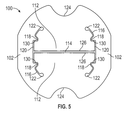
[0015] FIG. 5 is a plan view of another exemplary suture clip having pro-
alignment features.
[0016] FIG. 6 shows several of the suture clips of FIG. 5 mounted on a rail
in alignment.
[0017] FIG. 7 is a cross-sectional view of the loaded rail of FIG. 6, taken
at section 7-7.
CA 03103281 2020-12-09
WO 2020/010054 PCT/US2019/040252
¨ 4 ¨
[0018] FIG. 8 is a perspective view of the suture clip of FIG. 1 mounted on
a rail.
[0019] FIG. 9 is a perspective view of the suture clip of FIG. 5 mounted on
a rail.
[0020] FIG. 10 illustrates how an exemplary suture clip tab having a sharp
engagement edge can
become damaged.
[0021] FIG. 11 illustrates an exemplary suture clip tab having a rounded
engagement edge.
DETAILED DESCRIPTION
[0022] Described herein are improved suture clips and related devices and
methods for
securing sutures with suture clips. FIG. 1 illustrates an exemplary suture
clip 10 and FIG. 2 illustrates
several of the clips 10 mounted on a rail, or mandrel, 20 of deployment device
(see U.S. Patent
Application Publication No. 2016/0183937 Al for an exemplary deployment device
using a similar
clips-on-a-rail system). Additional information regarding procedures for which
the disclosed suture
clips and related delivery devices can be used, and other information
regarding exemplary suture
clips and suture clip delivery devices, are disclosed in the following
references, the entire contents of
which are expressly incorporated by reference herein: U.S. Patent Nos.
6,626,930; 7,094,244;
7,083,628; and 7,381,210; and U.S. Patent Application Publication Nos.
2007/0005079 Al and
2013/0165953 Al.
[0023] FIG. 3 is an exemplary cross-sectional profile of the rail 20,
showing a hollow central
region that can receive sutures during the clip deployment process. A delivery
device including the
rail 20 can be loaded with suture clips and can be used to deploy loaded
suture clips in succession
onto one or more sutures, such as during implantation of a prosthetic device
within the heart. The
disclosed suture clips can be used to secure a single suture, or can be used
to secure plural sutures
or suture segments at the same time.
[0024] The clip 10 is generally disk shaped and includes an annular outer
body and two
opposing tabs 12 defined by slots 14 and 16 passing through the clip. The slot
14 is between the
opposing edges of the two tabs 12, and is where sutures are engaged by the
clip to secure the clip
onto the sutures.
[0025] Any of the suture clips disclosed herein can comprise a resiliently
deformable material
that allows the opposing tabs to flex out of plane and apart from each other
and open a space
between the two tabs sufficient for the rail to pass through the clip between
the tabs, as shown in
CA 03103281 2020-12-09
WO 2020/010054 PCT/US2019/040252
¨ 5 ¨
FIGS. 2, 4, and 6-9. Any of the suture clips disclosed herein can be made from
a variety of materials
including, for example, nickel-titanium alloys, shape-memory alloys, stainless
steel, titanium, various
plastics, and other biologically-compatible materials. Exemplary suture clips
can be formed from
shape memory and/or pseudoelastic materials such as nitinol. In some
embodiments, the suture
clips can be formed from nitinol (e.g., with an alloy of nickel at about 54.5
¨ 57% by weight with
titanium accounting for the balance except for residual amounts (less than
about 0.05% each) of
oxygen, carbon, and hydrogen) or another shape memory and/or pseudoelastic
material, with the
suture clips formed so that the clip assumes its closed position (e.g., the
flat position shown in FIGS.
1 and 5) when in the austenite condition (e.g., when generally unstressed at
body temperature). The
nitinol can have an austenite finish temperature selected to match the
particular application. For
example, an austenite finish temperature of about ¨5 degrees to about +15
degrees Celsius may be
selected.
[0026] Any of the suture clips disclosed herein can comprise more than one
layer of material,
with the layers stacked in the thickness dimension of the clip. Each layer can
comprise a different
material. The outer surfaces of the clips can include coatings in some
embodiments. The thickness of
the clip and/or the diameter of the clip can be any sizes, and can be selected
based on the forces
needed properly secure target sutures, the materials of the clips, the tissues
through which the
sutures pass, and/or other factors. Similarly, the spacing and length of the
slot 114 between the
opposing tabs 112 can be selected based on the size and material of the
sutures to be secured and
based on the number of sutures (1, 2, 3, etc.) to be secured by each clip. In
some embodiments, the
suture engagement slot 114 can be non-straight, such as comprising zig-zag
portions or curved
portions, which can help contain the sutures in the middle of the slot.
[0027] A suture clip can be formed from material that will assume its
martensite condition
when subjected to sufficient stress, such as the stress applied to the clip's
suture engagement tabs
and annular outer body when the suture clip is mounted onto the rail, as shown
in FIGS. 4 and 6. In
such an embodiment, the rail applies stress to the engagement tabs, forcing
the tabs to open wide
enough to receive the rail through the opening between the tabs. The stressed
material, including
the bent material where the engagement tabs join the annular outer body, is
forced into its
martensite condition. When the stress is removed, such as when the rail slides
out from within the
distal-most clip during deployment, the material returns to its austenite
condition so that the
annular outer body and the engagement tabs assume their flat shape.
CA 03103281 2020-12-09
WO 2020/010054 PCT/US2019/040252
¨ 6 ¨
[0028] As illustrated in FIGS. 4 and 8, the clips 10 can sometimes become
misaligned on the rail
20. For example, in FIG. 4 the clip 22 can shifted out of alignment relative
to the rail and the other
clips. For example, the smooth round shape of the slots 16 in the suture clips
can allow the clips to
rotate about the rail enough to become misaligned. This misalignment can be
caused by a variety of
causes, such as manual error during the loading of the clips onto the rail,
impacts on the deployment
device while the clips are loaded in the device, or uneven forces on the clip
while the rail is slid
through the clips during deployment. Whatever the cause, misaligned clips can
fail to deploy
properly onto sutures and/or can jam the deployment device. This can lead to
increase time needed
to complete a surgery and/or failure of the clip to secure a suture, which can
increase the risk of
harm to a patient.
[0029] FIG. 5 is a plan view of an exemplary suture clip 100 that includes
rail alignment features
that help keep the suture clip properly oriented on a rail such as the rail
20, reducing the risk of the
suture clips becoming misaligned and failing to deploy properly onto sutures.
The clip 100 comprises
an annular outer body 102 and two opposing suture engagement tabs 112 that
extend inwardly
from the outer body. The clip 100 has a suture engagement slot 114 defined
between the tabs 112,
and two lateral slots 116 positioned at either end of the slot 114 and
separating the lateral sides of
the tabs 112 from the outer body 102. Each of the lateral slots 116 include
two steps 118, one on
either side of the suture engagement slot 114. The steps 118 are portions of
the slots 116 that
extends radially inwardly into the tabs 112 a short distance. The slots 116
also include a generally
straight portion 120 that extends between the two steps 118. The portion 120
can also be curved or
partially curved. At the ends of the slots 116 are relief openings 122 that
can reduce stress
concentrations when the tabs 112 are bent while mounted on a rail. The clip
100 also includes
opposing cutouts 124 that can help with gripping, loading, and/or manipulating
the clips relative to a
delivery device.
[0030] FIGS. 6, 7, and 9 illustrate the clip 100 mounted on a rail 20. When
the clip 100 is
mounted on a rail, the tabs flex out of plane relative to the outer body 102,
with the flexure
primarily occurring along hinge axes that extend between the relief openings
122, where the tabs
joint the outer body and the width of the tab is narrowest. The outer body 102
can also flex a small
amount in the opposite direction, as can be seen in FIG. 6, where the tabs 112
are extending to the
right and the outer body is flexed slightly to the left.
[0031] When mounted on the rail 20, the clips 100 are retained via opposing
clamping forces
applied to the rail by the edges 126 of the tabs 112. These clamping forces
are generated by the
CA 03103281 2020-12-09
WO 2020/010054 PCT/US2019/040252
¨ 7 ¨
resilient deformation of the clips in the mounted configuration, as the tabs
want to close back
together toward the closed neutral position shown in FIG. 5. These same forces
allow the tabs to
clamp onto sutures positioned between the tabs 112 once deployed from the
rail.
[0032] When mounted on the rail 20, the clips 100 are also held in
alignment relative to the rail
by surfaces 130 of the slot steps 118 and the walls of the slot portions 120.
The surfaces 130 can
contact the rail 20 and restrict the clips from tilting and shifting relative
to the rail, preventing the
misalignment such as the type shown in FIG. 4 with clip 22. There can be four
of the surfaces 130,
two on each of the lateral slots 116. The distance between each pair of
opposing surfaces 130 can be
selected to match the size of the rail 20. Similarly, the distance between the
walls of the slot
portions 120 can be selected to match the size of the rail. Together, the
portions of the clip 120 and
130 can act to bracket the rail 20 and maintain the clip in proper alignment
on the rail.
[0033] The features 118, 120, and 130 of the clips 100 can help the clips
to be mounted on the
rail in proper alignment during assembly; can help to prevent the clips from
inadvertently shifting
out of alignment or relaxing out of alignment after they are mounted on the
rail; and/or can help to
maintain the clips in proper alignment as the delivery device is actuated
during use and as the clips
100 are caused to slide longitudinally down the length of the rail step-by-
step, as each subsequent
clip is deployed during a surgical procedure (see U.S. Patent Application
Publication No.
2016/0183937 Al for exemplary deployment devices and methods).
[0034] FIGS. 10 and 11 show detailed views on the suture engagement edges
of two different
suture clips. FIG. 10 shows an exemplary suture engagement edge 200 (such as
can be present in
suture clip 10) that is a sharp and angular. Such a suture engagement edge can
be problematic, as
the sharp edge can cut or damage a suture and the sharp edge can more easily
become plastically
deformed and damaged, leading to particular matter coming loose from the
suture clip and harming
the patient. By contrast, FIG. 11 shows an exemplary suture engagement edge
300 (such as can be
present in suture clip 100) that is rounded and smooth, reducing/eliminating
the risk of the edge
becoming damaged, sutures being damaged by the edges, loose particulates
harming patients, etc.
The rounded edges 126 of the clip 100 also protect against damage when the
edges 126 are
contacting and sliding along the side of the rail 20, as in FIG. 6.
[0035] The suture clip 100, for example, can include four suture engagement
edges, two on
each tab 112. Each tab 112 can have one such edge on each side of the clip,
such that the clips are
symmetrical about a plane slicing through the middle of the thickness of the
clip. The clips can also
be symmetrical about planes cutting through the width of the clip along the
slot 114 and cutting
CA 03103281 2020-12-09
WO 2020/010054 PCT/US2019/040252
¨8¨
through the orthogonal width between the cutouts 124. In this way, the clips
can be used in any
orientation (e.g., flipped 180 degrees and/or rotated 180 degrees) so long as
the clip is oriented
relative to the rail 20 as shown in FIG. 7. This prevents accidental mis-
loading of the clips.
[0036] In some embodiments of the disclosed technology, the rail of the
deployment device
and/or the suture clips can include a coating or lubricant that reduces
friction between the suture
clips and the rail, which can make it easier to load and deploy the clips on
and off of the rail, and can
reduce scraping and particulate generation as the clips move over the rail.
The rail and/or the suture
clips can include a coating of a solid material and/or a viscous lubricant,
including dry and wet
lubricants. Exemplary coating/lubricant materials can include PTFE (e.g.,
DURAGLIDE dry PTFE
lubricant, MicroCare Medical, New Britain, Conn.) or other dry lubricants such
as, graphite, and
molybdenum disulfide; grease and other petroleum-based lubricants; polymer
based lubricants, for
example, silicone lubricants; metallic materials such as gold plating, and
other materials applied via
physical vapor deposition or chemical vapor deposition (e.g., CVD diamond or
diamond-like films);
and combinations thereof.
[0037] For purposes of this description, certain aspects, advantages, and
novel features of the
embodiments of this disclosure are described herein. The disclosed suture
clips, devices, methods,
and systems should not be construed as limiting in any way. Instead, the
present disclosure is
directed toward all novel and nonobvious features and aspects of the various
disclosed
embodiments, alone and in various combinations and sub-combinations with one
another. The
methods, apparatuses, and systems are not limited to any specific aspect or
feature or combination
thereof, nor do the disclosed embodiments require that any one or more
specific advantages be
present or problems be solved.
[0038] Features, characteristics, materials, compounds, integers, or groups
described in
conjunction with a particular aspect, embodiment or example of the invention
are to be understood
to be applicable to any other aspect, embodiment or example described herein
unless incompatible
therewith. All of the features disclosed in this specification (including any
accompanying claims,
abstract and drawings), and/or all of the steps of any method or process so
disclosed, may be
combined in any combination, except combinations where at least some of such
features and/or
steps are mutually exclusive. The invention is not restricted to the details
of any foregoing
embodiments. The invention extends to any novel one, or any novel combination,
of the features
disclosed in this specification (including any accompanying claims, abstract
and drawings), or to any
novel one, or any novel combination, of the steps of any method or process so
disclosed.
CA 03103281 2020-12-09
WO 2020/010054 PCT/US2019/040252
¨ 9 ¨
[0039] Although the operations of some of the disclosed methods are
described in a particular,
sequential order for convenient presentation, it should be understood that
this manner of
description encompasses rearrangement, unless a particular ordering is
required by specific
language. For example, operations described sequentially may in some cases be
rearranged or
performed concurrently. Moreover, for the sake of simplicity, the attached
figures may not show the
various ways in which the disclosed methods and devices can be used in
conjunction with other
methods and devices.
[0040] As used herein, the terms "a", "an", and "at least one" encompass
one or more of the
specified element. That is, if two of a particular element are present, one of
these elements is also
present and thus "an" element is present. The terms "a plurality of" and
"plural" mean two or more
of the specified element. As used herein, the term "and/or" used between the
last two of a list of
elements means any one or more of the listed elements. For example, the phrase
"A, B, and/or C"
means "A", "B", "C", "A and B", "A and C", "B and C", or "A, B, and C." As
used herein, the term
"coupled" generally means physically coupled or linked and does not exclude
the presence of
intermediate elements between the coupled items absent specific contrary
language.
[0041] In view of the many possible embodiments to which the principles of
the disclosure may
be applied, it should be recognized that the illustrated embodiments are only
preferred examples
and should not be taken as limiting the scope of the disclosure. Rather, the
scope of the disclosure is
at least as broad as the following claims. We therefore claim all that comes
within the scope of the
following claims.