Note: Descriptions are shown in the official language in which they were submitted.
PIVOTING SWIVEL ILLUMINATION DEVICE
Technical Field of the Invention
The present invention relates generally to illumination devices. More
particularly, the
present invention relates to illumination devices that pivot and/or swivel.
Background of the Invention
Illumination devices, such as flashlights, are often used in areas that are
dimly lit and
have restricted space, making it difficult to perform certain jobs. It is
preferable to mount the
illumination device in restricted spaces and aim the illumination device to
illuminate a desired
surface without requiring a user to hold the device. Illumination devices can
be coupled to
mountable bases that allow for some adjustment to aim the illumination device,
such as flashlight
holders. A variety of illumination devices are also known, such as LED
penlights, lights with
bendable shafts, platform lights mounted to bases that can slide and swivel,
etc. However,
current illumination devices are usually bulky, have limited aiming
adjustments, and/or require a
user to hold the device.
Summary of the Invention
The present invention broadly relates to an illumination device, such as a
compact
flashlight, a lamp, a magnifying glass, etc., having a body with attributes of
a swivel/universal
socket and/or typical ball-and-socket joint for 360 degree adjustment and one
or more
illumination sources disposed along an internal perimeter of the body. The
illumination device
can have a base adapted to be releasably coupled to surfaces and illuminate a
specified area by
aiming the illumination device without the need to move the base. Once the
illumination device
is aimed to illuminate the area of interest, the body will remain in this
position until further
1
Date Recue/Date Received 2020-12-21
manipulated by the user. Once aimed, the user does not need to hold the device
in position.
Accordingly, the illumination device is more compact and has improved aiming
adjustments as
compared to the current art.
In an embodiment, the present invention broadly includes an illumination
device
.. including a base adapted to releasably couple to a surface, a body coupled
to the base with a
pivoting coupling, and an illumination source disposed along an internal
perimeter of the body.
Brief Description of the Drawings
For the purpose of facilitating an understanding of the subject matter sought
to be
protected, there are illustrated in the accompanying drawings embodiments
thereof, from an
.. inspection of which, when considered in connection with the following
description, the subject
matter sought to be protected, its construction and operation, and many of its
advantages should
be readily understood and appreciated.
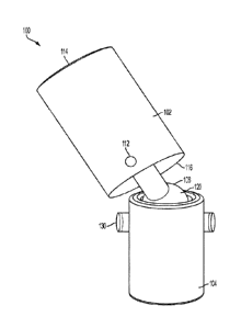
FIG. 1 is a perspective view of an illumination device according to an
embodiment of the
present invention.
FIG. 2 is another perspective view showing a body of the illumination device
of FIG. 1 in
a different position.
FIG. 3 is another perspective view showing a body of the illumination device
of FIG. 1 in
a different position.
FIG. 4 is a section view of the illumination device of FIG. 1 taken along line
A-A of FIG.
3.
FIG. 5 is a side perspective view of an illumination device according to
another
embodiment of the present invention.
2
Date Recue/Date Received 2020-12-21
FIG. 6 is a section view of the illumination device of FIG. 5 taken along line
A-A of FIG.
5.
FIG. 7 is a side perspective view of an illumination device according to
another
embodiment of the present invention.
FIG. 8 is a section view of the illumination device of FIG. 7 taken along line
A-A of FIG.
7.
FIG. 9 is a perspective view of a base of the illumination device of FIG. 1
according to an
embodiment of the present invention.
FIG. 10 is a perspective view of a base of the illumination device of FIG. 1
according to
another embodiment of the present invention.
FIG. 11 is a perspective view of a base of the illumination device of FIG. 1
according to
another embodiment of the present invention.
FIG. 12 is a section view of a body of the illumination device of FIG. 1 taken
along line
A-A of FIG. 3 according to another embodiment of the present invention.
FIG. 13 is a section view of a body of the illumination device of FIG. 1 taken
along line
A-A of FIG. 3 according to another embodiment of the present invention.
Detailed Description of the Embodiments
While this invention is susceptible of embodiments in many different forms,
there is
shown in the drawings, and will herein be described in detail, a preferred
embodiment of the
invention with the understanding that the present disclosure is to be
considered as an
exemplification of the principles of the invention and is not intended to
limit the broad aspect of
the invention to embodiments illustrated. As used herein, the term "present
invention" is not
3
Date Recue/Date Received 2020-12-21
intended to limit the scope of the claimed invention and is instead a term
used to discuss
exemplary embodiments of the invention for explanatory purposes only.
The present invention broadly relates to an illumination device including a
base adapted
to releasably couple to a surface, a body coupled to the base with a pivoting
coupling, and one or
more illumination sources disposed along an internal perimeter of the body.
Referring to FIGs. 1 through 13, an illumination device 100 may be removably
coupled
to a surface to direct where additional illumination is desired. The
illumination device 100 can
have 360 degrees of adjustability by swiveling and/or pivoting to allow the
user to aim the light
where needed.
The illumination device 100 may include a body 102 and a base 104. The base
104 is
rotatably and/or pivotably coupled to the body 102 via a pivoting coupling
106, which will be
discussed in more detail below. The illumination device 100 may be a lamp, a
magnifying glass,
a flashlight, or any other suitable device that provides illumination to a
dimly lit area.
The body 102 may be hollow and cylindrical. Although, the body 102 may be
various
geometric shapes, such as rectangular, square, etc., and adapted to contain an
illumination source
108, a power source 110, a switch 112, etc., which will be discussed in more
detail below.
The body 102 can include a first end 114 and a second end 116. The first end
114 can be
open to allow light from the illumination source 108 to pass through.
Additionally, or
alternatively, the first end 114 can include a light cover 118 or lens to
prevent debris from falling
into the body 102 and/or to diffuse the light emitting from the illumination
source 108.
The pivoting coupling 106 can be a ball and socket coupling that includes a
ball 120 and
a socket. The ball 120 can be coupled to or formed on the second end 116 of
the body 102. The
ball 120 is adapted to fit inside and be retained by the socket of the
pivoting coupling 106. In an
4
Date Recue/Date Received 2020-12-21
embodiment, a pin 130 and the base 104 may function as the socket, discussed
below. In another
embodiment, a retaining cap 122 and the base 104 may function as the socket,
discussed below.
The pivoting coupling 106 allows the body 102 to swivel and/or pivot 360
degrees relative to the
base 104.
The illumination source 108 can be long lasting, low power consumption LEDs or
other
suitable light emitting sources, such as light bulbs or the like. The
illumination source 108 is
positioned and directed to emit light from the body 102, as described above.
The illumination
source 108 can be disposed along an internal perimeter of the body 102. As
shown in FIGs. 4 and
6, the illumination source 108 can be disposed along an internal circumference
proximate to the
.. first end 114 of the body 102. In an embodiment the illumination source 108
can be disposed
along an internal circumference proximate to an end of the pivoting coupling
106, as shown in
FIG. 8. In an embodiment, the illumination source 108 is disposed along an
internal
circumference proximate to a center of the body 102, as shown in FIGs. 12 and
13. In an
embodiment, the illumination source 108 is arranged in an axial direction
along interior walls of
the body 102, as shown in Fig. 12. In an embodiment, the illumination source
108 is disposed in
a radial direction along an interior surface 124 of the body 102 and in an
axial direction along the
interior walls of the body 102, thereby forming a "U" (not shown).
The power source 110 is adapted to provide energy to illuminate the
illumination source
108. The power source 110 can be or can include, but is not limited to, a
battery, such as a DC
battery, a rechargeable battery, or the like. In an embodiment, the power
source 110 can be AC
power. If a rechargeable power source, the charging means can be wired or
wireless. The power
source 110 can be housed in a separate compartment 126 within the body 102. If
desired, the
power source 110 can be accessible by removing a portion of the body 102, such
as a battery
5
Date Recue/Date Received 2020-12-21
door (not shown), to recharge or replace the battery as needed. The power
source 110 also need
not be housed within the body 102. The power source 110 can instead be housed
in the base
104.
The switch 112 can be positioned on or in the body 102 or the base 104. The
switch 112
can have an actuation mechanism that employs a push button actuator, switch,
or other type of
actuator to activate or operate the switch 112. In an embodiment, the switch
112 can be a toggle
actuator, a touch sensitive actuator, a slide actuator, or other suitable
actuator or device. The
switch 112 is used to turn the illumination source 108 ON and OFF. In another
embodiment (not
shown) the switch 112 is actuated when the illumination device 100 is coupled
to a surface using
a connection means 134, which is discussed in more detail below. In this
embodiment, the
illumination source 108 can be turned ON and OFF without requiring the
operator to push the
actuation mechanism. When the illumination device 100 decouples from the
surface, the
illumination device is turned OFF.
As discussed above, the switch 112, the power source 110, the illumination
source 108,
and other components can be housed within the body 102. In another embodiment,
the switch
112, the power source 110, the illumination source 108, and/or the other
components can be
housed within the ball 120 of the ball and socket coupling. In this
embodiment, the illumination
device 100 may not include the body 102, as shown in FIGs. 7 and 8. The
illumination device
100 may also include a circuit board (not shown) to which the various
components are coupled.
The switch 112, the power source 110, and the illumination source 108 can be
connected to the
circuit board and thus to one another via the board, as is known in the art.
The illumination
source 108 may be disposed on the board. Wires may be used to connect the
various
components to the circuit board. Electrical contacts can be provided as well
between the various
6
Date Recue/Date Received 2020-12-21
components and the circuit board. The functional design of these components
can vary
considerably within the spirit and scope of the present invention.
The base 104 may be hollow and cylindrical, although the base 104 may be other
various
geometric shapes as well, such as square, rectangular, etc. The base 104 can
have an open end
adapted to receive and retain the ball 120. In an embodiment, the base 104 can
be adapted to
function as a socket of the ball and socket coupling. This can be achieved
various ways,
including, but not limited to, the use of the pin 130 passing though the ball
120, or with the
retaining cap 122 coupled to the base 104 and adapted to retain the ball 120
in the base 104. For
the pin style embodiment, the base 104 can have two apertures 128 adapted to
receive the pin
.. 130 that retains the ball 120 in the base 104. In the retaining cap style
embodiment, the base 104
can be coupled to the retaining cap 122 to retain the ball 120 therein and
compress the spring
132. The retaining cap 122 can be pressed, crimped, threaded, or the like on
the base 104.
A spring 132 may be housed in the base 104. The spring 132 can be preloaded to
exert an
axial force against the ball 120. This axial force allows the body 102 to
maintain its position
without user manipulation. In another embodiment (not shown) a spring 132 can
apply a radial
force against the ball 120. The radial force allows the body 102 to maintain
its position without
user manipulation. The spring 132 can be a coil spring, or other suitable
biasing member that can
provide the axial or radial force to maintain the illuminated position of the
illumination device
100.
In an embodiment, the base 104 can include a connection means 134 that allows
for
hands free use of the illumination device 100. The connection means 134 can be
coupled to or
otherwise mounted on a bottom, outside surface of the base 104 (as shown in
FIG. 10), a side of
the base 104 (as shown in FIG. 9), or in a cavity 136 inside the base 104 on a
bottom, inside
7
Date Recue/Date Received 2020-12-21
surface of the base 102 (as shown in FIG. 11). In another embodiment (not
shown), the
connection means 134 can be coupled to or otherwise mounted on an outside
surface of the cap
122. The connection means 134 may be a magnet that allows the illumination
device 100 to be
coupled to a ferromagnetic surface. The connection means 134 can also be a
clamp, a suction
cup, or any other suitable means that allows for hands free use of the
illumination device 100.
As used herein, the term "coupled" and its functional equivalents are not
intended to
necessarily be limited to direct, mechanical coupling of two or more
components. Instead, the
term "coupled" and its functional equivalents are intended to mean any direct
or indirect
mechanical, electrical, or chemical connection between two or more objects,
features, work
pieces, and/or environmental matter. "Coupled" is also intended to mean, in
some examples, one
object being integral with another object.
The matter set forth in the foregoing description and accompanying drawings is
offered
by way of illustration only and not as a limitation. While particular
embodiments have been
shown and described, it will be apparent to those skilled in the art that
changes and modifications
may be made without departing from the broader aspects of the inventors'
contribution. The
actual scope of the protection sought is intended to be defined in the
following claims when
viewed in their proper perspective based on the prior art.
8
Date Recue/Date Received 2020-12-21