Note: Descriptions are shown in the official language in which they were submitted.
CA 03103556 2020-12-11
WO 2019/238650
PCT/EP2019/065162
LENS WITH COLOR ENHANCEMENT
FIELD OF THE INVENTION
[1] The invention relates to ophthalmic lenses having a plurality of light
attenuating dyes.
The inclusion of a plurality of light attenuating dyes affords enhanced color
contrast by selectively
filtering specific light wavelength ranges.
BACKGROUND
[2] Electronic displays have traditionally included contrast-adjustment
controls for tuning
the picture to fit the preference of the viewer. In visual perception of the
real world, modulation of
contrast is a relatively new technology.
[3] Contrast is the difference in color that makes one object
distinguishable from another
object. Contrast is determined by the difference in color and brightness
between different objects
within the same field of view. In order to adjust contrast for real world
color perception, lenses
must be capable of tuning specific frequency ranges of visible light that are
transmitted through the
lens. For example, attenuating transmittance of green and red light results in
enhanced perception
of blue and yellow light.
[4] Although contrast enhancement is subjective based on individual
preferences of lens
wearers, certain contrast-enhancing features can be combined to enhance
perception of primary
colors. For example, reducing light transmission in the wavelength regions
that overlap the primary
colors enhances the primary colors.
[5] Contrast enhancing features can also be combined with polarizing
filters for improved
contrast enhancement. Glare observed in outdoor conditions, which is
specularly reflected sun
light, is often partially polarized white light and compounds reflected light
from colored surfaces.
Glare typically saturates the hue of natural surface colors. Blocking the hue-
saturating glare is an
additional method for enhancing color contrast.
[6] Today, as a result of improved understanding of the physics of vision,
lenses can be
produced that protect a user's eyes from UV light, IR light, and glare by
selectively filtering light
traveling through the lens. There is a need in the industry, however, for
improving the perception
of primary colors and enhancing color contrast.
CA 03103556 2020-12-11
WO 2019/238650
PCT/EP2019/065162
2
SUMMARY
[7] The invention relates to the ophthalmic lens described in claim 1.
Other advantageous
and non-limitative features of this ophthalmic lens are described in claims 2
to 15. Disclosed herein
are methods for incorporating specific combinations of color-reducing dyes
into lenses for
improving color contrast. Transmittance-attenuating dyes provide localized
regions of reduced
light transmission across specific wavelength regions, i.e., localized
transmittance minima. By
incorporating dyes that reduce light transmittance across specific regions,
non-reduced wavelength
regions appear as regions with relatively higher transmittance, i.e.,
localized transmittance maxima.
The inclusion of specific dyes into a lens enhances color contrast by tuning
local minima and
maxima to achieve the desired transmission spectrum.
[8] Transmittance-attenuating dyes can be selected to reduce transmittance
across a desired
wavelength range. Dye concentration can be selected to adjust the degree of
reduction in
transmittance. The total number of dyes can be adjusted to customize the
transmission spectrum.
By combining multiple dyes, various transmittance profiles can be tailored for
specific applications.
[9] In some aspects, a method for producing an ophthalmic lens comprising a
polymerized
lens comprising at least one polymer, and a lens component configured to
impart reduced light
transmittance over a plurality of wavelength regions is provided. The lens
component configured to
impart reduced light transmittance over a plurality of wavelength regions may
include at least two
dyes, each of which imparts a region of reduced light transmittance. In some
embodiments, the lens
polymer is a polycarbonate (PC) resin.
[10] In one embodiment, a first light transmittance-reducing dye may
be selected to impart a
first region of reduced light transmittance having a center located between
about 485 nanometers
and 510 nanometers. In some aspects, a second light transmittance-reducing dye
may be selected to
impart a second region of reduced light transmittance having a center located
between about 570
nanometers and 600 nanometers of reduced light transmittance. In some aspects,
a second light
transmittance-reducing dye may be selected to impart a second region of
reduced light
transmittance having a center located between about 685 nanometers and 715
nanometers. In some
embodiments, the light transmittance-reducing dye selected to impart a region
of reduced light
transmittance having a center located between about 570 nanometers and 600
nanometers is
employed as a third, optional light transmittance-reducing dye. In some
embodiments, the light
transmittance-reducing dye selected to impart a region of reduced light
transmittance having a
center located between about 685 nanometers and 715 nanometers is employed as
a third, optional
light transmittance-reducing dye. In some embodiments, reduced light
transmittance is defined as a
CA 03103556 2020-12-11
WO 2019/238650
PCT/EP2019/065162
3
reduction in % transmittance of at least 50% as compared to a region outside a
reduced light
transmittance region and between 400 nanometers and 680 nanometers.
[11] In some aspects, the lens component configured to impart reduced light
transmittance is
a polymerized lens. The polymerized lens may include a blend of at least one
polymer and the
light-transmittance reducing dyes. Lenses may optionally be fitted with one or
more polarizing
layers to produce sunglass applications with tailored transmittance-reduction
regions. Both
prescription and piano lenses having localized attenuated transmittance
regions may be produced.
Various lens embodiments can be tailored and produced for specific lens
environments, including
general color enhancement, driving glasses, lenses for foggy conditions,
lenses for snow/skiing,
fishing, flying, hunting, and other environments in which reduction of
transmittance across specific
color regions can be utilized to enhance color perception and differentiation
of colors.
[12] When the light-transmittance reducing dyes are incorporated into a
polarizing wafer
construct, the wafer construct imparts reduced light transmittance properties
onto the the lens. The
polarizing wafer construct may include at last one layer comprising the light
transmittance-reducing
dyes. In some embodiments, the at least one layer comprising the light
transmittance-reducing dyes
may be an injection-molded layer comprising a blend of a polymer and the dyes.
In other
embodiments, the at least one layer comprising the light transmittance-
reducing dyes is a film layer
adhered to the polarizing wafer construct.
[13] In some embodiments, the lens component configured to impart reduced
light
transmittance is a coating matrix. A high refractive index coating matrix may
be provided to
increase refractive index, in some embodiments. A durability-enhancing coating
matrix may be
provided to impart hot water resistance, weathering resistance, light
resistance, scuffing resistance,
abrasion resistance, and/or impact resistance to the lens. A coating matrix
may be provided to a
concave or convex lens surface. Non-limiting examples of coating matrices
include polyurethane-
and epoxy-based coating matrices.
[14] In some embodiments, the lens component configured to impart reduced
light
transmittance is a multilayer interferential film stack. A plurality of
transmittance-attenuating dyes
can be incorporated into an interferential stack that interferes with or
modifies properties of light
transmitted through the interferential stack. One example of an interferential
stack comprises a
plurality of interferential thin layers. Alternating layers of a dielectric
material of high refractive
index and a dielectric material of low refractive index may be provided to a
lens substrate to reduce
its light reflection and therefore to increase its light transmission. In some
aspects, an interferential
stack comprises a metal organic framework. In some aspects, the multilayer
interferential film
stack is a film laminate residing on a surface of the ophthalmic lens. The
surface of the ophthalmic
CA 03103556 2020-12-11
WO 2019/238650
PCT/EP2019/065162
4
lens may be the concave surface or the convex surface. In some embodiments,
the multilayer
interferential film stack resides on or within the polarizing wafer construct.
[15] In some embodiments, a plurality of light transmittance-reducing dyes
may be
incorporated into an adhesive. The adhesive may then be incorporated in the
lens to adhere two
layers to one another. In some embodiments, the adhesive comprising a
plurality of light
transmittance-reducing dyes is an adhesive layer within a polarizing wafer
construct. In some
embodiments, the adhesive comprising a plurality of light transmittance-
reducing dyes resides
between a polarizing wafer construct and a polymerized lens. In some
embodiments, a tint layer
may be provided with a plurality of light transmittance-reducing dyes. The
light transmittance-
reducing dyes may then be incorporated into or onto a lens by conventional
tinting methods known
to those of skill in the art.
[16] In some embodiments, a polarizing wafer construct comprises an inner
polyvinyl alcohol
polarizing layer residing between two outer layers, wherein each outer layer
is independently made
from polycarbonate, cellulose triacetate, polyamide, thermoplastic
polyurethane, or poly(methyl
methacrylate). In some embodiments, a polymerized lens base material may be
provided with
additional components for reducing the transmittance of UV and/or short-
wavelength blue light.
[17] In some embodiments, light transmittance-reducing dyes are
independently provided in
amount ranging from 1 to 100 ppm. This range may be adjusted to include values
outside this range
if warranted. For example, a composition in which a light transmittance-
reducing dye is sparing
soluble may have less than 1 ppm of the dye. By contrast, a composition in
which a light
transmittance-reducing dye is very soluble may include greater than 100 ppm of
the dye. The dyes
may be selected from azo dyes, polymethyne dyes, arylmethyne dyes, polyene
dyes,
anthracinedione dyes, pyrazolone dyes, anthraquinone dyes, isoindolinone dyes,
auinophtalone
dyes, naphthalenediamine dyes, and carbonyl dyes.
[18] Dyes are defined by the Ecological and Toxicological Association of
Dyes and Organic
Pigment Manufacturers as colored or fluorescent organic molecules which impart
color to a
substrate by selective absorption of light. Dyes are soluble and/or go through
an application
process which, at least temporarily, destroys any crystal structure by
absorption, solution, and
mechanical retention, or by ionic or covalent chemical bonds.
[19] The phrases "transmittance reducing", "transmittance attenuating",
"color absorbing"
are used interchangably herein. "Ophthalmic lens," according to the
disclosure, is defined as a lens
adapted, namely for mounting in eyeglasses, whose function is to protect the
eye and/or to correct
vision. This lens can be an afocal, unifocal, bifocal, trifocal, or
progressive lens. The ophthalmic
lens may be corrective or un-corrective. Eyeglasses wherein ophthalmic lenses
will be mounted
CA 03103556 2020-12-11
WO 2019/238650
PCT/EP2019/065162
could be either a traditional frame comprising two distinctive ophthalmic
lenses, one for the right
eye and one for the left eye, or like mask, visor, helmet sight or goggle,
wherein one ophthalmic
lens faces simultaneously the right and the left eyes. Ophthalmic lenses may
be produced with
traditional geometry as a circle or may be produced to be fitted to an
intended frame. Ophthalmic
5 lenses may be provided with at least one polarizing component to provide
a polarized ophthalmic
lens, for example, sunglasses.
[20] A "polymerized lens comprising at least one polymer" can include a
thermally-
polymerizable composition, a photo-polymerizable composition, or a mixture
thereof. A thermally-
polymerizable composition is a composition where polymerization occurs upon
exposure to an
elevated temperature. A photo-polymerizable composition is a composition where
polymerization
occurs upon exposure to actinic radiation including, but not limited to, UV,
visible, IR, microwave,
etc. As used herein polymerizing or polymerization refer to a chemical
reaction that results in
bonding of one or more monomers or oligomers to each other to form a polymer.
[21] Any embodiment of any of the disclosed compositions and/or methods can
consist of or
consist essentially of¨rather than comprise/include/contain/have¨any of the
described elements
and/or features and/or steps. Thus, in any of the claims, the term "consisting
of' or "consisting
essentially of' can be substituted for any of the open-ended linking verbs
recited above, in order to
change the scope of a given claim from what it would otherwise be using the
open-ended linking
verb.
[22] The term "substantially" and its variations are defined as being
largely but not
necessarily wholly what is specified as understood by one of ordinary skill in
the art, and in one
non-limiting embodiment substantially refers to ranges within 10%, within 5%,
within 1%, or
within 0.5%.
[23] The term "about" or "approximately" or "substantially unchanged"
are defined as being
close to as understood by one of ordinary skill in the art, and in one non-
limiting embodiment the
terms are defined to be within 10%, preferably within 5%, more preferably
within 1%, and most
preferably within 0.5%. The use of the word "a" or "an" when used in
conjunction with the term
"comprising" in the claims and/or the specification may mean "one," but it is
also consistent with
the meaning of "one or more," "at least one," and "one or more than one." As
used in this
specification and claim(s), the words "comprising" (and any form of
comprising, such as
"comprise" and "comprises"), "having" (and any form of having, such as "have"
and "has"),
"including" (and any form of including, such as "includes" and "include") or
"containing" (and any
form of containing, such as "contains" and "contain") are inclusive or open-
ended and do not
exclude additional, unrecited elements or method steps.
CA 03103556 2020-12-11
WO 2019/238650
PCT/EP2019/065162
6
[24] The compositions and methods for their use can "comprise," "consist
essentially of," or
"consist of' any of the ingredients or steps disclosed throughout the
specification. With respect to
the transitional phase "consisting essentially of," in one non-limiting
aspect, a basic and novel
characteristic of the compositions and methods disclosed in this specification
includes the
compositions' abilities to reduce light transmittance over a plurality of
wavelength regions.
[25] Other objects, features and advantages of the present invention will
become apparent
from the following detailed description. It should be understood, however,
that the detailed
description and the examples, while indicating specific embodiments of the
invention, are given by
way of illustration only. Additionally, it is contemplated that changes and
modifications within the
spirit and scope of the invention will become apparent to those skilled in the
art from this detailed
description.
BRIEF DESCRIPTION OF THE FIGURES
[26] FIGS. 1A-1B are graphs depicting various lenses having multiple is a
graph depicting
transmission spectra of a base lens and various lens embodiments having
multiple transmittance-
attenuating dyes.
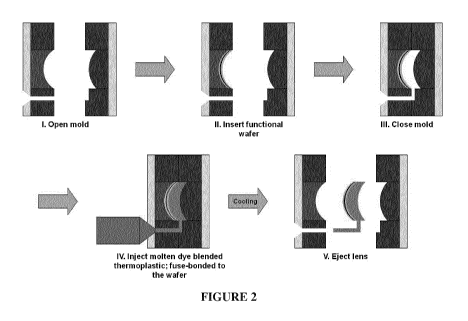
[27] FIG. 2 is a schematic depicting the incorporation of transmittance-
attenuating dyes into
lens resin material.
[28] FIGS. 3A-3B are schematics depicting the incorporation of
transmittance-attenuating
dyes into a polarizing wafer construct by injection molding (FIG. 3A) and
subsequent over-
molding of the polarizing wafer construct onto an injection molded lens (FIG.
3B).
[29] FIG. 4 a schematic depicting the incorporation of a film comprising
transmittance-
attenuating dyes into a polarizing wafer construct.
DETAILED DESCRIPTION
[30] Various features and advantageous details are explained more fully
with reference to the
non-limiting embodiments that are illustrated in the accompanying drawings and
detailed in the
following description. It should be understood, however, that the detailed
description and the
specific examples, while indicating embodiments, are given by way of
illustration only, and not by
way of limitation. Various substitutions, modifications, additions, and/or
rearrangements will be
apparent to those of ordinary skill in the art from this disclosure.
[31] In the following description, numerous specific details are provided
to provide a
thorough understanding of the disclosed embodiments. One of ordinary skill in
the relevant art will
CA 03103556 2020-12-11
WO 2019/238650
PCT/EP2019/065162
7
recognize, however, that the invention may be practiced without one or more of
the specific details,
or with other methods, components, materials, and so forth. In other
instances, well-known
structures, materials, or operations are not shown or described in detail to
avoid obscuring aspects
of the invention.
[32] The color enhancement features disclosed herein may be provided to a
lens through a
variety of manufacturing methods. In some embodiments, the color enhancement
features are
afforded by incorporating one or more transmittance reducing dyes into at
least one lens
component. Although the methods by which the one or more dyes are provided,
and the location of
the one or more dyes within the lens may differ, comparable performance is
achieved.
EXAMPLES
Method 1: Dyes Pre-Blended Into Base Lens Resin
[33] Method 1 was used to fabricate Examples A through D using a
polycarbonate (PC) resin
containing broad band UV absorbing dyes. In some examples, additional light
attenuating dyes are
included to further reduce %Tv and provide additional color enhancement. As
used herein, a
category 2 wafer has a %Tv in the range of 19%-45%, whereas a category 3 wafer
has a %Tv in the
range of 8%-18%. Different category wafers are employed to provide lenses with
different %Tv.
[34] Referring to the embodiment depicted in FIG. 2, a polarizing PC wafer
having no color
enhancing dyes was over-molded onto a pre-blended PC resin to provide a semi-
finished (SF) lens.
The pre-blended PC resin contained a mixture of two or three dyes formulated
to provide two or
three attenuated transmission spectral ranges, respectively.
[35] Examples A and B included three dyes to provide transmission minima
centered at
around 495nm, 585nm and 700nm. Examples C and D included two dyes to provide
transmission
minima centered at around 495 nm and 585 nm. The SF lenses were subsequently
surfaced to piano
(no vision correction) with a center thickness of 2 mm. All lenses were
designed to meet ISO
standards for driving (Q signals and %Tmin).
Table 1 Spectral Region Transmittance Attenuating Dyes
Dye Number Attenuation Region Center
Dye 1 495 nm
Dye 2 585 nm
Dye 3 700 nm
CA 03103556 2020-12-11
WO 2019/238650
PCT/EP2019/065162
8
[36] The dye concentrations identified in the Examples below are nominal
concentrations.
Actual concentrations may vary slightly from nominal concentrations due to
losses that may occur
during the tumbling, mixing, or other production processes.
[37] Example A: Pre-blended PC resin + Category 2 grey wafer (%Tv - 34%,
Polarization
efficiency >97%).
Table 2: Example A Pre-Blended PC Resin Dyes
Dye Number Concentration
Dye 1 22.8 ppm
Dye 2 33.8 ppm
Dye 3 22.4 ppm
[38] Example B: Pre-blended PC resin + Category 3 grey wafer (%Tv - 17%,
Polarization
efficiency >99%).
Table 3 Example B Pre-Blended PC Resin Dyes
Dye Number Concentration
Dye 1 23.8 ppm
Dye 2 32.1 ppm
Dye 3 8.9 ppm
[39] Example C: Pre-blended PC resin + Category 2 grey wafer (%Tv - 34%,
Polarization
efficiency >97%).
Table 4: Example C Pre-Blended PC Resin Dyes
Dye Number Concentration
Dye 1 22.3 ppm
Dye 2 33.8 ppm
CA 03103556 2020-12-11
WO 2019/238650
PCT/EP2019/065162
9
[40] Example D: Pre-blended PC resin + Category 3 grey wafer (%Ty -
17%, Polarization
efficiency >99%).
Table 5: Example D Pre-Blended PC Resin Dyes
Dye Number Concentration
Dye 1 22.3 ppm
Dye 2 32.1 ppm
[41] Example E: Pre-blended PC resin + Category 2 wafer (%Ty - 35%,
Polarization
efficiency >99%).
Table 6: Example E Pre-Blended PC Resin Dyes
Dye Number Concentration
Dye 1 22.6 ppm
Dye 2 33.9 ppm
Airwear Color Blue Gil 9.1%
[42] Example F: Pre-blended PC resin + Category 2 wafer (%Ty - 35%,
Polarization
efficiency >99%).
Table 7: Example F Pre-Blended PC Resin Dyes
Dye Number Concentration
Dye 1 23.1 ppm
Dye 2 33.9 ppm
Dye 3 25.0 ppm
Airwear Color Blue Gil 6.9%
[43] The transmission spectra of lens Examples A-D, along with that of a
standard category 3
grey polarizing lens (with no color enhancement) are depicted in FIG. 1A.
Example A includes
CA 03103556 2020-12-11
WO 2019/238650
PCT/EP2019/065162
three localized transmittance-attenuated regions owing to the inclusion of
three dyes in the pre-
blended PC resin. In Example B, the amount of Dye 3, having a transmittance-
attenuating region
centered at around 700 nm, was significantly reduced, in comparison to Example
A. The
transmission spectra of Example B shows a transmittance-attenuated region at
around 700 nm in
5 which the transmittance is greater than the corresponding region in
Example A. These two
Examples demonstrate that dye concentrations can be modified in order to
selectively adjust
transmittance in a desired region.
[44] In the lenses corresponding to Examples C and D, two transmittance-
attenuating dyes
were included in the respective pre-blended PC resins. The Example C and D
transmission spectra
10 in FIG. IA depict two localized transmittance-attenuated regions owing
to the inclusion of two
dyes in the pre-blended PC resins.
[45] In the lenses corresponding to Examples E and F, the lens PC resin was
pre-compounded
with a combination of dyes (Airwear Color Blue G11) that absorb evenly in most
wavelength
regions and reduce total overall transmission. Two additional transmittance-
attenuating dyes were
added to the PC resin for Example E. Three additional transmittance-
attenuating dyes were added
to the PC resin for Example F. The Example E and F transmission spectra in
FIG. IB exhibit two
and three localized transmittance-attenuating regions, respectively, owing to
the inclusion of a
corresponding number of dyes in the pre-blended PC resins.
Method 2: Dyes Incorporated Into Polarizing Wafers
[46] Transmittance-attenuating dyes can be incorporated into various lens
components. In
the embodiments described in Method 2, the dyes are integrated into one or
more layers of a
polarizing wafer construct. Options A and B below describe two distinct
methods for incorporating
transmittance-attenuating dyes into polarizing wafer constructs.
[47] Option A: A polarizing wafer construct may be over-molded onto a
thin resin layer
having a plurality of dyes using an injection molding process. Referring to
FIG. 3A, a polarizing
wafer construct is inserted into a mold, and the mold is closed with adequate
space for injection of a
thin layer. A resin is then injected into the mold and fuse-bonds to the
polarizing wafer construct.
The thin injected layer includes a plurality of transmittance-attenuating
dyes, and is designated
"CE1" for its color-enhancing features.
[48] In the embodiment depicted in FIG. 3A, the polarizing wafer construct
is a PC/PVA/PC
polarizing wafer construct, and the injected resin is a thermoplastic resin
having a plurality of
transmittance-attenuating dyes. The exemplary PC/PVA/PC/CE1 polarizing wafer
produced by this
CA 03103556 2020-12-11
WO 2019/238650
PCT/EP2019/065162
11
method is subsequently over-molded onto a semi-finished lens using a
conventional clear resin, in
accoradnce with the process depicted in FIG. 3B.
[49] Option B: An optical quality film (CE2) having a plurality of
transmittance-attenuating
dyes may be laminated onto a polarizing laminate, for example, a PC/PVA
polarizing laminate to
provide a PC/PVA/CE2 polarizing wafer construct. As depicted in FIG. 4, the
color-enhanced
polarizing wafer construct may be over-molded onto a thermoplastic resin. The
resulting lens
includes dyes in the CE2 layer residing between the polarizing PVA layer and
the base injection-
molded lens. Because pre-manufactured films may be thinner than an injection-
molded layer,
Option B (film incorporation) is preferred over Option A (injection molding).
The optical quality
film (CE2) may be made or an optical resin selected from a variety of optical
grade thermoplastics,
including but not limited to PC, Nylon, and thermoplastic polyurethane (TPU).
Method 3: Dyes Incorporated Into A Coating Matrix
[50] Transmittance-attenuating dyes may be integrated into a coating matrix
that may
subsequently be deposited onto a lens. A high refractive index coating matrix
may be provided to
increase refractive index. A durability-enhancing coating matrix may be
provided to impart hot
water resistance, weathering resistance, light resistance, scuffing
resistance, abrasion resistance,
and/or impact resistance to the lens. A coating matrix may be provided to a
concave or convex lens
surface, or anywhere between outermost lens surfaces.
Method 4: Dyes Incorporated Through Tinting Processes
[51] Transmittance-attenuating dyes can incorporated into or onto an
ophthalmic element by
a tinting process. Transmittance-attenuating dyes can be incorporated into or
onto a lens by either
selecting transmittance-attenuating dyes that are specifically designed to
adhere to the base lens
material or substrate material to be tinted, or by first coating a base lens
or other substrate with a
thin veneer of resin which not only adheres to the lens or substrate but also
has a high affinity for
dyes. The dyes may be mixed and provided to the lens as a combination of dyes,
or each dye may
be provided separately. Standard tinting processes known to those of skill in
the art may be
employed, including but not limited to dip tinting and thermal transfer
tinting (sublimation).
Method 5: Spectral Tuning By Using An Interferential Stack
[52] Transmittance attenuation to selectively reflect light at
specific wavelengths can be
introduced by using an interferential stack that interferes with or modifies
properties of light
transmitted through the interferential stack. An interferential stack may
comprise a plurality of
interferential thin layers. Alternating layers of a dielectric material of
high refractive index and a
CA 03103556 2020-12-11
WO 2019/238650
PCT/EP2019/065162
12
dielectric material of low refractive index may be provided to a lens
substrate to reduce its light
transmission in specific wavelength regions. Additionally a plurality of dyes
can be introduced into
an interferential stack to further attenuate light transmission through the
interferential stack.
Method 6: Dyes Incorporated Into Adhesive
[53] A plurality of transmittance-attenuating dyes can be incorporated a
lens adhesive. The
dye-supplemented adhesive may subsequently be incorporated between lens layers
to adhere the
layers. In a non-limiting embodiment, one or more transmittance-attenuating
dyes may be
incorporated into an adhesive that is then used to adhere layers of a
polarizing PC/PVA/PC
laminate.
The polarizing laminate may then be over-molded onto a SF as described in
Method 1
above.
[54]
The claims are not to be interpreted as including means-plus- or step-plus-
function
limitations, unless such a limitation is explicitly recited in a given claim
using the phrase(s) "means
for" or "step for," respectively.