Note: Descriptions are shown in the official language in which they were submitted.
87617073
1
Title: CATALYST FOR CATALYTIC OXIDATIVE CRACKING OF
HYDROGEN SULPHIDE WITH CONCURRENT HYDROGEN
PRODUCTION
Field of the invention
The invention pertains to a catalyst suitable for a catalytic oxidative
process for recovering sulphur from a LS-containing gas stream. The invention
also pertains to a method for recovering sulphur from such gas stream, using
the
catalyst. Furthermore, the invention pertains to the production of hydrogen
associated with a sulphur recovery process using the catalyst.
Background of the invention
Sulphur Recovery Plants are designed to remove H2S from H2S-containing
acid gases from Amine Regeneration Systems and from Sour Water Strippers
producing sulphur, a non-toxic product which can be stored and sold in liquid
or
in solid form to different users for several different industrial
applications. The
acid gases from Amine Regeneration Systems and Sour Water Strippers,
containing a variable amount of I-12S, are treated in a Sulphur Recovery Unit
(SRI T), generally based on the modified Claus process, for bulk sulphur
recovery
and subsequently in a Tail Gas Treatment (TGT) section for deep sulphur
recovery. Other impurities contained in the sour gases, including ammonia and
hydrocarbons, are destroyed in the Claus section.
The modified Claus process by itself recovers about 94+96% (2 catalytic
stages) or 95+98% (3 stages) of the sulphur in the feedstock. A further
treatment
of the Claus tail gas is therefore necessary when a higher Sulphur Recovery
Efficiency (SRE) is required.
The modified Claus process comprises a sub-stoichiometric combustion of
the acid gas stream in a thermal reactor (thermal stage) followed by catalytic
conversion in the Claus reactors (catalytic stage). In the Claus section one-
third
Date Recue/Date Received 2022-04-08
CA 03103962 2020-12-15
WO 2019/240586 2 PCT/NL2019/050370
of the total H2S is oxidized to SO2, which reacts with the remaining H2S to
form
sulphur and water according to the following reactions:
112S + 1.5 02 ¨> H20 + SO2 (oxidation reaction) (1)
2 H9S + SO2 4-> 1.5 S9 2 H20 (Claus reaction) (2)
3 119S + 1.5 09 4-> 3 H20 + 1.5 S2 (overall reaction) (3)
The goal of the process is to drive the overall reaction to near completion.
In the Claus thermal reactor, the H2S contained in the acid gas is burnt with
air
(or with oxygen-enriched air in some specific cases) in a specific burner and
only
one-third of the total 119S is oxidized to SO2, while the remaining two-third
is not
reacted. The total air amount is the one exactly sufficient to oxidize one-
third of
the total H2S and to completely oxidize all hydrocarbons and ammonia contained
in the feedstock; the molar ratio 112S/02 in the feedstock is therefore about
2:1 in
order to get a ratio 112S/S02 in the Claus tail gas of exactly, or as close as
possible
to, 2:1, which is the stoichiometric ratio for the Claus reaction, so
maximizing
Sulphur Recovery Efficiency. During acid gas combustion, a small part of the
H2S
(typically 5+7%) is dissociated to hydrogen and sulphur as per following
reaction:
112S 4-* 112 + 0.5 S9 (dissociation or cracking reaction) (4)
According to Clark et al., Alberta Sulphur Research Ltd. (ASRL), hydrogen
formation also happens according to the following reaction:
4 H2S + 09 4- 2 H2 + 2 1120 + 2 S9 (H9 formation reaction) (5)
Several side reactions are also involved, leading to the destruction of
ammonia and hydrocarbons and to the formation of carbonyl sulphide COS and
carbon disulphide CS2. In order to complete the Claus reactions, a suitable
residence time is necessary at high temperature in the thermal reactor.
The Claus thermal reactor is typically followed by a waste heat boiler
where furnace effluent is cooled down to about 300 C and heat is recovered by
raising high pressure steam and by a sulphur condenser where process gas is
cooled down to sulphur dew point by raising low pressure steam and liquid
sulphur is separated.
The Claus thermal stage is generally followed by two or three catalytic
stages, each one composed by a gas reheater to bring the gas to the optimal
CA 03103962 2020-12-15
WO 2019/240586 3
PCT/NL2019/050370
reaction temperature, a catalytic reactor where the Claus reaction takes place
and a sulphur condenser where gas is cooled and liquid sulphur is condensed
and
separated. The Claus reaction is an exothermic equilibrium reaction
thermodynamically enhanced by low temperatures. The first Claus catalytic
reactor is partly filled with a Claus catalyst (Alumina based) to enhance the
Claus reaction and partly filled with a specific high conversion catalyst
(Titania
based) to enhance the hydrolysis of COS and CS2. The second and third Claus
catalytic reactors, if any, are generally filled with Claus catalyst (Alumina
based)
to enhance Claus reaction.
In order to satisfy the >99% sulphur recovery efficiency normally required
for a Sulphur Recovery Plant, the Claus section is generally followed by a
Tail
Gas Treatment section. Several different alternative processes have been
proposed over the years to boost Sulphur Recovery Efficiency, like the SCOT
method, the RAR process, the CBA process, the CLINSULF/DEGSULF method
or the BSR Selectox process. In the traditional reductive Tail Gas Treatment
section, the process gas from a Claus section is preheated and combined with
hydrogen from an external source prior to being fed to a hydrogenation
reactor,
where all sulphur compounds are converted to ELS over a specific reduction
catalyst (Co and Mo oxides based), which performs both the hydrogenation and
the hydrolysis functions. The reactor effluent is cooled down in the quench
tower
by means of circulating steam condensate. The 112S produced in the
hydrogenation reactor is recovered in an amine absorber with a specific amine
aqueous solution and recycled to the Claus section from the top of an amine
regenerator, where the enriched solution is stripped.
The tail gas from the amine absorber is sent to a thermal incinerator for
the oxidation of residual H9S and other sulphur compounds, such as COS and
CS2, to SO2 prior to disposal to the atmosphere via a dedicated stack.
The main drawbacks of traditional Claus Plant are the need for large and
expensive equipment against very low sulphur economic value, continuous
-- emissions of SO x (SO2 and SO3), CO, CO2, NO plus traces of H2S into the
atmosphere, and continuous import of hydrogen from the network, for process
gas reduction in the TGT section.
CA 03103962 2020-12-15
WO 2019/240586 4 PCT/NL2019/050370
In some plants, where hydrogen is not available, for example in gas fields,
the reducing gas mixture is generated in a reducing gas generator by sub-
stoichiometric fuel gas combustion. The main drawback of such alternative
configuration is the larger equipment size compared to traditional Claus
Plant.
This is caused by the 10-15% higher process gas flow rate due to large amounts
of
inerts coming from in-line fuel gas combustion ((mainly nitrogen from air and
water and carbon dioxide from combustion).
As mentioned in Clark, Catalysis Communications 5 (2004) 743-747, the
recovery of H2 from H2S is a long-standing goal in industry. Clark addresses
this
by means of the partial oxidation of H2S over alumina catalysts. Key to this
process is said to be the promotion of the reaction of H2S and 02 under the
formation of hydrogen, water, and sulphur at a controlled temperature by means
of an external oven. Reduction of emissions into the atmosphere is not
addressed.
Some alternative processes have been proposed over the years, which are
.. addressed to thermal or catalytic partial oxidation of H2S.
US Patents Nos. 6,946,111 and 6,800,269 by Conoco Inc. disclose processes
for removing 112S from a 119S-containing gas stream the first one and from a
H9S-
rich waste gas stream the second one, comprising a flameless short contact
time
reactor filled with a suitable catalyst for partial oxidation reaction of H2S
to form
sulphur and water, using air or enriched air or pure oxygen with a H2S/02
ratio
in the feedstock of approximately 2:1, followed by a cooling zone and by a
sulphur
condenser. The main goal of the first Patent is to de-sulphurize a gas stream,
while the main goal of the second Patent is to propose an alternative solution
to
the traditional thermal reactor in a Claus Plant. Both Patents are based on
hydrogen sulphide catalytic partial oxidation reaction with oxygen to form
sulphur and water.
US Patent No. 7,560,088 by Conoco Phillips Company discloses a process
for removing sulphur from a H2S-containing gas stream using a compact system
comprising a flameless short contact time catalytic partial oxidation reaction
zone followed by a temperature-control zone, a first Claus catalytic reaction
zone,
a second temperature-control zone, a first liquid sulphur outlet and a first
effluent gas outlet. The main goal of this Patent is to propose an alternative
CA 03103962 2020-12-15
WO 2019/240586 5
PCT/NL2019/050370
solution to traditional Claus Plant based on hydrogen sulphide catalytic
partial
oxidation to form sulphur and water.
US Patent No. 4,481,181 by GA Technologies Inc. discloses a process for
removing sulphur and recovering hydrogen from a 119S-containing gas stream
.. coupling thermal partial oxidation of H2S to sulphur and water and thermal
dissociation of H2S to hydrogen and sulphur in the same reaction zone,
preceded
by feedstock heating section and followed by a cooling zone and by a sulphur
condenser, using pure oxygen and a substantial proportion of nitrogen with a
H2S/09 ratio in the feedstock between 10:1 and 25:1. The main goal of this
Patent
is to thermally decompose by partial oxidation and dissociation hydrogen
sulphide into sulphur and hydrogen.
W02010/036941 by Chevron U.S.A. Inc. and Drexel University discloses a
method for performing H2S thermal dissociation at temperature below 1600 C
based on H and SH radicals, in one embodiment over a suitable plasma catalyst.
Furthermore, Italian Patent 1 203 898 by Siirtec-Nigi discloses a process
called HCR based on the operation of the traditional Claus thermal reactor at
a
slightly higher H2S/02 ratio in the feedstock in order to keep a H2S/S02 ratio
in
the Claus tail gas significantly higher than 2:1. The main goal of this
process is to
boost hydrogen production in thermal reactor and to avoid hydrogen import in
the TGT section. Also with such a process, Sulphur Recovery Plant emissions
are
not avoided.
From the above discussion, it is evident that several efforts have been
made in the past, trying to propose a valid alternative to traditional Claus
Plant.
In particular, some processes which have been proposed over the years are
based
on the thermal or catalytic partial oxidation of H2S, while some other
processes
are focused on the thermal or catalytic cracking of H2S. None of the proposed
processes is conceived and arranged to perform H2S conversion to hydrogen and
sulphur over a suitable catalyst able to favour both reactions at the same
time.
In W02012/154041, a method is described for the production of hydrogen
from a H2S-containing gas stream, comprising subjecting the gas stream to
catalytic oxidative cracking so as to form 112 and S9. The invention described
CA 03103962 2020-12-15
WO 2019/240586 6 PCT/NL2019/050370
therein serves to address the problem of gas emissions into the atmosphere and
producing at the same time a valuable hydrogen export stream.
An issue with H2S-containing gas streams as these are regularly provided
to sulphur recovery facilities, is the co-presence of methane and/or heavier
hydrocarbons. In particular, methane is prone to being converted in sulphur
compounds such as CS9 or COS, which is undesirable.
Another issue with US-containing gas streams as these are regularly
provided to sulphur recovery facilities, is the co-presence of ammonia. The
ammonia is typically converted in the thermal stage of the Claus plant.
However,
the thermal conversion of ammonia embodies a risk, occurring upon incomplete
burning, of the formation of solid salts such as ammonium sulphides or
sulphites.
These salts cause blockage in the coldest sections of the Claus plant, in
particular
in the sulphur condensers. In order to burn the ammonia properly, a
homogeneous mixture of ammonia and air is required, along with a high flame
temperature. However, the formation of nitrogen oxides encourages the
oxidation
of sulphur dioxide, SO2, to sulphur trioxide, S03. The Claus catalyst then
becomes sulphided and the cold portions of the unit are seen to corrode.
W02014/073966 provides a catalyst that is active and selective in the
oxidative cracking of H2S particularly in the event of the concomitant
presence of
NH3 and/or CH4, and more generally, carbon containing compounds. The catalyst
comprises iron and molybdenum on a carrier comprising aluminium, e.g.
alumina.
However, reducing the sintering tendency at high temperatures remains a
challenge in the field of catalytic oxidative cracking of hydrogen sulphide.
In
another aspect, it is desirable to increase the stability of the catalyst, for
example
by reducing the vapour pressure of the active phases at high temperatures
during catalytic oxidative cracking of hydrogen sulphide. In one additional
aspect, a higher stability is particularly desired to meet the ever more
stringent
market requirements for the End Of Run (EOR) conditions of the catalyst. In
this
respect, it is particularly favourable to reduce the ammonia concentration at
the
outlet of the reactor.
CA 03103962 2020-12-15
WO 2019/240586 7
PCT/NL2019/050370
If one or more of these challenges is tackled, the catalyst is more stable at
high temperatures than described in the prior art. In some aspects of the
invention, this advancement would lead to a higher conversion of H9S during
the
reaction. Furthermore, a higher stability at high temperatures may also result
in
prolonged lifetimes of the catalyst.
As further background art, reference is made to Jiratova et al. Chinese
Journal of Catalysis, volume 37, pages 258-267. This refers to
hydrodesulfurization activities of a NiM0 catalysts supported on
mecahnochemically prepared Al-CE mixed oxides. The active metal herein is
NiMo6.
Summ.ary of the invention
In order to better address one or more of the foregoing desires, the
invention presents, in one aspect, a catalyst composition suitable for the
catalytic
oxidative cracking of a H2S-containing gas stream, the catalyst composition
comprising at least one active metal selected from the group consisting of Fe,
Co,
Ni, and combinations thereof, supported by a carrier comprising ceria and
alumina, and preferably with the proviso that the active metal does not
comprise
NiMo6. This proviso is preferred for the catalyst product as such and is
optional
for the catalyst as used in the plant, in the hydrogen production method, and
for
the catalyst prepared in the catalyst preparation method as described herein.
The catalyst as comprised in the plant, as used in the hydrogen production
method or as prepared with the catalyst preparation method in some
embodiments comprise NiMo6 and some other embodiments are different from
NiMoG.
The invention also pertains to a method for the production of hydrogen
from a H2S-containing gas stream, comprising subjecting the gas stream to
catalytic oxidative cracking so as to form 112 and S2, using a catalyst
comprising
at least one active metal selected from the group consisting of iron, cobalt,
nickel,
and combinations thereof, wherein said active metal is supported by a carrier
comprising ceria and alumina.
87617073
8
According to another aspect of the present invention, there is provided a
catalyst comprising a carrier and nickel as the sole catalytically active
metal for the
catalytic oxidative cracking of a H2S-containing gas stream, wherein said
active
metal is supported by said carrier and wherein said carrier comprises ceria
and
alumina.
According to another aspect of the present invention, there is provided a
catalyst comprising a carrier and at least one active metal, wherein the at
least one
active metal selected from the group consisting of iron, cobalt, nickel, and
combinations thereof; wherein the active metal is in the form of its sulphide;
wherein the active metal in its sulphide form is present in the catalyst in a
range
from 8 to 25 wt.%, wherein the catalyst is a powder and the concentrations are
expressed based on the total weight of catalyst; or the catalyst comprises a
mechanical substrate and catalytic layer and the concentrations are expressed
based on the total weight of the catalytic layer; wherein the support
comprises ceria
and alumina, wherein the support has a ratio weight of ceria X 100%
weight of cerin+weight of alumina
of 10% to 30%.
According to another aspect of the present invention, there is provided a
plant adapted for conducting the catalytic oxidative cracking of a H2S-
containing
gas stream, said plant comprising an inlet for a H2S-containing acid gas
stream, an
inlet for an oxygen-comprising stream, and a Catalytic Oxidative Cracking
reaction
zone, comprising a H2S partial oxidation and a cracking catalyst; wherein the
catalyst comprises catalytic material that comprises one or more catalysts
comprising at least one active metal selected from the group consisting of
iron,
cobalt, nickel, and combinations thereof, wherein said active metal is
supported by
a carrier comprising ceria and alumina; wherein the plant further comprises a
gas
quench zone downstream from the reaction zone, and a waste heat boiler and a
sulphur condenser arranged downstream of the gas quench zone to cool down the
process gas and to recover liquid sulphur.
In another aspect, the catalyst compositions of the invention are suitable for
the catalytic oxidative cracking of a H2S-containing gas stream in the event
of a
Date Recue/Date Received 2022-04-08
87617073
9
concomitant presence of NH3 and/or CH4, and/or carbon containing compounds. In
yet another aspect, the H2S-containing stream may further comprise compounds
selected from the group consisting of COS, RSH, HCN, benzene, toluene,
ethylbenzene, and xylene.
In another aspect, the invention pertains to a method of making a catalyst as
defined above or as used in said method, comprising providing an aqueous
solution
of precursors for nickel, selected from the group consisting of nickel
tetracarbonyl,
nickel nitrates, nickel bromides, nickel chlorides, nickel fluorides, nickel
phosphates, nickel sulphates, nickel acetylacetonates, nickel acetates, nickel
fumarates, nickel gluconates, nickel citrates, nickel benzoates, nickel
maleates,
nickel oxalates, nickel oleates, nickel stearates, nickel-ammonium complexes,
iron
tetracarbonyl, iron pentacarbonyl, iron nonacarbonyl, iron nitrates, iron
bromides,
iron chlorides, iron fluorides, iron phosphates, iron sulphates, iron
acetylacetonates,
iron acetates, iron fumarates, iron gluconates, iron citrates, iron benzoates,
iron
maleates, iron oxalates, iron oleates, iron stearates, iron stearates, iron-
ammonium
complexes, cobalt tetracarbonyl, cobalt pentacarbonyl, cobalt nonacarbonyl,
cobalt
nitrates, cobalt bromides, cobalt chlorides, cobalt fluorides, cobalt
phosphates,
cobalt sulphates, cobalt acetylacetonates, cobalt acetates, cobalt fumarates,
cobalt
gluconates, cobalt citrates, cobalt benzoates, cobalt maleates, cobalt
oxalates, cobalt
oleates, cobalt stearates, and cobalt-ammonium complexes.
In a still further aspect, the invention provides a method for the production
of
hydrogen from a H2S and optionally NH3 and/or CH4-containing gas stream,
comprising subjecting the gas stream to catalytic oxidative cracking so as to
form H2
and S2, using a catalyst as defined above.
The invention also pertains to a plant suitable for conducting the catalytic
oxidative cracking of a H2S-containing gas stream, said plant comprising an
inlet
for a H2S-containing acid gas stream, an inlet for an oxygen-comprising
stream, and
a Catalytic Oxidative Cracking reaction zone, comprising a catalytic material
suitable for H2S partial oxidation and cracking, wherein the catalytic
material
comprises one or more catalysts at least one active metal selected from the
group
Date Recue/Date Received 2022-04-08
87617073
9a
consisting of Fe, Co, Ni, and combinations thereof, supported by a carrier
comprising ceria and alumina; preferably wherein the catalyst is as defined
above.
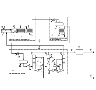
Brief description of the drawings
Figure 1 schematically illustrates an example plant according to an embodiment
of
the invention.
Detailed Description of Example Embodiments of the Invention
The invention, in a broad sense, is based on the recognition of a judicious
combination of at least one catalytically active metal selected from the group
consisting of nickel (Ni), iron (Fe), cobalt (Co), and mixtures thereof, with
a support
comprising ceria and alumina. Preferably, the catalyst composition comprises
Ni,
more preferably the active metal is Ni, i.e., the sole active metal is nickel
in any
suitable form, such as a sulphide.
It is believed that a support comprising ceria and alumina lowers the
sintering tendency. Surprisingly, the compositions of the invention result in
a
reduced vapour pressure of the active phase comprising the active metal,
preferably
in its sulphide form at the desired reaction conditions. Without wishing to be
bound
by theory, it is believed that the lowered sintering tendency and/or the
reduced
vapour pressure of the active phase lead to an improved thermal stability. In
turn,
this higher thermal stability is believed to result in improved catalytic
performance
as higher conversions can be obtained. Moreover, prolonged lifetimes of the
catalysts are also a result of the higher thermal stability.
In another aspect, the catalysts of the invention are believed to be
advantageous in terms of End of Run conditions. When compared to previously
disclosed catalysts operating for a similar duration, the catalysts of the
invention
are able to reduce the ammonia concentration at the outlet of the reactor. Or,
alternatively, when used with reference to obtaining the same ammonia
concentration as obtained by using previously disclosed catalysts, the novel
catalysts are stable for a longer period of time.
Date Recue/Date Received 2022-04-08
CA 03103962 2020-12-15
WO 2019/240586 10
PCT/NL2019/050370
A supported catalyst will be understood as pertaining to a catalyst
composition comprising a catalytically active part (i.e. particles as provided
that
are either active, or are converted into an active phase in situ), and a
catalytically non-active part, wherein the catalytically non-active part (the
support) generally forms the majority of the catalyst. This distinguishes a
supported catalyst from a bulk-catalyst, in which the catalytically non-active
part
is generally the minority. Thus, in a supported catalyst, the catalytically
non-
active part is generally more than 50% by weight of the catalyst composition.
Preferably the support forms more than 60% by weight, more preferably more
than 70% by weight, and most preferably more than 80% by weight, of the total
catalyst composition. In some embodiments, the support does not form more than
90% by weight of the total composition, more preferably not more than 87% by
weight, most preferably not more than 83% by weight.
The catalytically active part of the catalyst composition comprises at least
one element of period 4 of the VMS group. In particular, the active metal is
selected from the group consisting of Fe, Co and Ni. The metal is typically
present in the form of particles dispersed onto the support, in an amount of
at
least 1 wt.% and generally up to 50 wt.% by weight of the catalyst
composition.
The support comprises alumina, i.e., (A1203). The alumina can be, e.g., alpha-
or
theta or gamma-alumina. Furthermore, the support comprises ceria (Ce02).
The support typically comprises ceria and alumina in a weight ratio for
ceria (i.e.
weight of ceria X
100%) of 2% to 50%, preferably in a ratio of
weL.ght of ceria+weight of alumina
5% to 40%, more preferably 10% to 30%.
The catalytically active metal in its sulphided form is present in the
catalyst composition in a range typically of 1 to 40% by weight, preferably
from 3
to 35% by weight, more preferably from 5 to 30% by weight, most preferably
from
8 to 25% by weight, for example 17% by weight as compared to the total weight
of
the catalyst composition when the catalyst is present as a powder, or compared
to
the total weight of the catalytic layer when the catalyst comprises a
mechanical
substrate.
In some embodiments, the appropriate reaction chamber can be charged
with unsulphided catalyst and the active metal can be sulphided by exposing
the
CA 03103962 2020-12-15
WO 2019/240586 11 PCT/NL2019/050370
catalyst to the gas stream to be treated for a certain time, preferably from 3
to 12
hours in order to sulphide the active metal and activate the catalyst.
The catalyst may consist essentially of the catalyst composition, i.e. the
alumina- and ceria-containing carrier, and the active metal contained thereon.
If
so, the catalyst will generally be in a suitably shaped form, e.g. a powder, a
sphere or a pellet. The catalyst may also, in addition to the catalyst
composition
comprising a carrier or support and the active metals, contain a mechanical
support structure, i.e. a substrate.
It will be understood that such a substrate is not part of the catalyst
.. composition as defined above, but comes in addition thereto. A substrate
may be
any structure known in the art as a substrate for catalysts. In one embodiment
of
the present invention, the substrate may be in the form of beads, pellets,
spheres,
honeycomb monolith or open cell foams. The substrate may be formed from
alumina, silica alumina, silica, titania, mixtures thereof, or any other
suitable
.. material as available in the field of catalyst substrates.
If the catalyst comprises a substrate, then this will typically be coated
with the supported catalyst composition of alumina, ceria, and at least one
active
metal as defined above.
In a preferred embodiment, the catalytically active metal is in the form
of its sulphide. For example, nickel preferably is in the form of nickel
sulphide,
iron preferably is in the form of iron sulphide, and cobalt is preferably in
the form
of cobalt sulphide.
The catalyst composition of the invention can be prepared in a manner
known to the skilled person. Reference is made, e.g., to "Catalyst Handbook",
.. M.V. Twigg (Ed.), Wolfe Publishing Ltd, 1989, and to "Structured Catalysts
And
Reactors", A. Cybulski and J.A. Moulijn (Eds.), Marcel Dekker Inc., 1998 ¨
Chapter 21 (Transformation of a structured carrier into structured catalyst),
pp.
599-615.
In a particularly suitable method, an aqueous solution is provided of a
precursor, and dispersing the solution onto a carrier material. Examples of
nickel-containing precursors are inorganic and organic nickel salts, nickel
chelates, nickel clusters, nickel hydroxides and oxi-hydroxides, and nickel
CA 03103962 2020-12-15
WO 2019/240586 12 PCT/NL2019/050370
organometallic complexes. Representative of these compounds are nickel
tetracarbonyl, nickel nitrates, nickel bromides, nickel chlorides, nickel
fluorides,
nickel phosphates, nickel sulphates, nickel acetylacetonates, nickel acetates,
nickel fumarates, nickel gluconates, nickel citrates, nickel benzoates, nickel
maleates, nickel oxalates, nickel oleates, nickel stearates, nickel-ammonium
complexes, and the like. In one aspect, the catalyst precursors comprise at
least
one metal selected from the group consisting of Ni(0), Ni(l), Ni(II), Ni(III),
and
Ni(IV). Preferably Ni(II) is used. Examples of iron-containing precursors are
inorganic and organic iron salts, iron chelates, iron clusters, iron
hydroxides and
oxi-hydroxides, and iron organometallic complexes. Representative of these
compounds are iron tetracarbonyl, iron pentacarbonyl, iron nonacarbonyl, iron
nitrates, iron bromides, iron chlorides, iron fluorides, iron phosphates, iron
sulphates, iron acetylacetonates, iron acetates, iron fumarates, iron
gluconates,
iron citrates, iron benzoates, iron maleates, iron oxalates, iron oleates,
iron
stearates, iron stearates, iron-ammonium complexes and the like. In one
aspect,
the catalyst precursors comprise at least one metal selected from the group
consisting of Fe(0), Fe(I), Fe(II), Fe(III), Fe(IV), Fe(V), Fe(VI), and
Fe(VII).
Preferably, Fe(II) and/or Fe(III) is used. Examples of cobalt-containing
precursors
are inorganic and organic cobalt salts, cobalt chelates, cobalt clusters,
cobalt
hydroxides and oxi-hydroxides, and cobalt organometallic complexes.
Representative of these compounds are cobalt tetracarbonyl, cobalt
pentacarbonyl, cobalt nonacarbonyl, cobalt nitrates, cobalt bromides, cobalt
chlorides, cobalt fluorides, cobalt phosphates, cobalt sulphates, cobalt
acetylacetonates, cobalt acetates, cobalt fumarates, cobalt gluconates, cobalt
citrates, cobalt benzoates, cobalt maleates, cobalt oxalates, cobalt oleates,
cobalt
stearates, and cobalt-ammonium complexes and the like. In one aspect, the
catalyst precursors comprise at least one metal selected from the group
consisting of Co(0), Co(I), Co(II), Co(III), Co(IV), and Co(V). Preferably,
Co(II) is
used. The catalyst precursors may further comprise organic ligands or anions
such as acetate, citrate, EDTA (ethylene cliamine tetra acetate) or NTA
(nitrilo
triacetate).
CA 03103962 2020-12-15
WO 2019/240586 13 PCT/NL2019/050370
In a particularly preferred embodiment, the carrier is first calcined prior to
the impregnation with a solution of the precursor. Calcination is preferably
performed at a temperature higher than 700 C, more preferably at least 750 C,
even more preferably in the range 750-1100 C, most preferably in the range 900-
1100 C. The duration of the calcination process at the desired temperature is
preferably in a range of 10 to 30 hours, more preferably in a range of 13 to
30
hours. The calcination process is preferably performed under isothermal
conditions. Preferably, the calcination is performed in the presence of
oxygen,
more preferably, in air. After the calcination, the active catalyst metal is
applied
to the calcined support as described above. For example, wet impregnation or
precipitation of the catalytic metal can be used. Without wishing to be bound
by
theory, it is believed that the calcination as described above allows to
stabilize
the structure of the catalyst. In this way, the obtained catalyst is
particularly
suitable for the high temperatures, e.g. 1100 C, involved in the catalytic
oxidative cracking. In this embodiment, it is important to do the calcining
step
first to produce a stabilized support and subsequently apply the catalytic
metal to
it. If the process is carried out in reverse, it is believed that the catalyst
structure
could change in the way that the catalytic metal would not be available for
the
catalytic reaction.
Preferably, another step of calcination is performed after deposition of the
active phase. In some aspects, this additional step of calcination may be
carried
out under the same conditions and following the same procedures as mentioned
above for the first step of calcination.
The invention further pertains to a method for the production of hydrogen
.. from a H2S-containing gas stream, comprising subjecting the gas stream to
catalytic oxidative cracking so as to form 112 and S2, using a catalyst as
defined
above.
It is emphasized that the catalytic oxidative cracking in accordance with
this aspect of the invention is a fundamentally different process from both
the
thermal stage and the catalytic stage in an existing Claus-type process. With
reference to the reaction equations (1) to (5) mentioned above, the Claus
processes are directed to driving the above reaction (3) to near completion.
The
CA 03103962 2020-12-15
WO 2019/240586 14 PCT/NL2019/050370
present invention is based on the judicious insight to provide a process based
on
the side reactions (4) and (5), and to promote these reactions for the
production,
from a H2S-containing gas-stream, of both hydrogen and sulphur.
The process of the invention is also fundamentally different from the
recent proposals by Clark et al. The references authored by the latter, are
based
on a theory of direct oxidation of H2S under the formation of hydrogen, water
and
sulphur. The resulting conversion, whilst avoiding the formation of SO2, is
subject to improvement as to the conversion of H2S and the production of
sulphur
concurrently with 112.
In the present invention a Catalytic Oxidative Cracking (COC) stage
substitutes the Claus thermal stage and/or both the Claus thermal stage and
the
Claus Catalytic Stages. The process of the invention thus favours 112S
dissociation and partial oxidation instead of complete oxidation and Claus
reaction. However, it is not excluded to add a Claus thermal stage and/or a
Claus
catalytic stage after the COC stage.
The catalytic oxidative cracking is conducted in one or more reaction zones,
preferably provided in one reaction chamber. Throughout the text the term
"chamber" may relate to one or more reaction zones. A reaction chamber is
defined as a reactor volume with optionally a catalyst bed. In a single
reaction
chamber there is only a single type of catalyst. Typically, the reaction
chamber is
substantially cylindrical and the reactant flow is in the axial direction. If
the
reaction chamber comprises a catalyst bed, one or more reactions may take
place
in the axial direction of the gas flow. In an embodiment where more than one
reaction is taking place, the reaction conversion profile for one reaction may
be
different from that from another reaction. In other words, one reaction may be
taking place, e.g., mostly at the beginning of the catalyst bed, whilst the
other
reaction may take place, e.g., over the total length of the catalyst bed.
The invention presents the skilled person with the insight to promote the
above-mentioned reactions (4) and (5). The fact that thereto the gas stream is
to
be subjected to catalytic oxidative cracking, implies a clear message to the
skilled
person as to how to carry this out.
CA 03103962 2020-12-15
WO 2019/240586 15 PCT/NL2019/050370
In general, the catalyst will be provided, in a conventional manner, on a
catalyst bed over which the gas stream to be treated is led. The choice of the
types of beds and volumes thereof are well within the ambit of the skilled
person's normal capabilities.
The Catalytic Oxidative Cracking reaction zone or zones are provided with
oxygen. The oxygen is preferably provided as a gas enriched with oxygen as
compared to air. Preferably, this is an oxygen-containing gas-stream
comprising
at least 40 vol.% oxygen, preferably at least 60 vol.% oxygen. More
preferably,
this oxygen is provided as substantially pure oxygen, viz. 90 vol.%-99 vol.%
of
oxygen, or as close to 100% as available.
The use of oxygen-enriched gas, and preferably pure oxygen, is not only
related to optimizing the catalytic oxidative cracking process, it also
presents
advantages such as the avoidance of an unnecessarily large equipment, which
would be needed on account of the presence of large volumes of inert
(nitrogen)
gas. Moreover, with reference to the invention's purpose to produce hydrogen,
in
addition to sulphur recovery and with reduced emissions, it will be
advantageous
to reduce, and preferably avoid, the presence of nitrogen in the tail gas of
the
process.
The quantity of oxygen fed to the reactor is selected so as to achieve a ratio
H2S/02 in the feedstock higher than the typical figure of about 2:1.
Preferably,
H9S/02 ratio in the feedstock should be in the range 2:1-6:1 or preferably
higher
than 2:1 and up to 6:1, more preferably in the range 3:1-5:1, still more
preferably
in the range 3.5:1-4.5:1, even more preferably in the range 3.9:1-4.7:1, most
preferably in the range 4:1-4.5:1.
In the preferred embodiment of operating the catalytic oxidative cracking
on the basis of a ratio 112S/02 between 4:1 and 4.5:1, most preferred between
4.1:1
and 4.5:1, preferred reaction temperatures to obtain simultaneously cracking
and
partial oxidation of H2S are in the range 700 C -1300 C, preferably in the
range
of 800 C -1300 C, more preferably in the range of 950 C -1250 C. Most
preferably
a temperature in the range of 1050-1100 C is obtained.
CA 03103962 2020-12-15
WO 2019/240586 16
PCT/NL2019/050370
In one embodiment, the molar ratio of NH3/02 in the feedstock is between
0.1 and 1.5. Preferably, the molar ratio of N113/02 in the feedstock is
between 0.1-
1.2, more preferably between 0.1-1, most preferably between 0.3-1.
In one embodiment, the feedstock to Catalytic Oxidative Cracking reaction
zone or zones (H2S-containing acid gas and oxygen-containing gas) is preheated
in order to increase the reaction temperature, to boost hydrogen production
and
to depress SO2 formation.
In one embodiment of the present invention, the H2S-containing acid gas
and the oxygen-containing gas are mixed in a static mixer just before entering
the catalytic bed of the Catalytic Oxidative Cracking reaction zone or zones.
In one embodiment the hydrogen concentration in the effluent of the
reaction chamber (after quenching) is at least 3 vol%, preferably at least 5
vol%
most preferred at least 7 vol%.
It should be noted that the reaction preferably is conducted autothermally.
This refers to the fact that, whilst the process is preferably adiabatic, heat
exchange takes in fact place, since the oxidation reaction is exothermic, and
the
cracking reaction is endothermic, whereby heat made available through the
exothermic reaction is utilized in the endothermic reaction.
All in all, the process of the invention, by virtue of the judicious choice of
catalyst, is believed to favour reactions (4) and (5) relative to reactions
(1) and
(2), leading to lower H2S conversion, but on the other hand to significantly
higher
112 formation and to much lower SO2 formation. As a consequence of the lower
112S conversion, a higher acid gas recycle rate from H2S-containing gas source
(e.g. an amine regenerator) to reaction chamber is obtained as compared to a
traditional Claus Plant.
The catalytic oxidative cracking process of the invention serves to reduce
the temperature so as to provide the required reaction equilibrium. This
results
in increasing the hydrogen yield and minimizing SO2 formation, which in turn
serves to minimize hydrogen consumption in the Tail Gas Treatment section to
reduce SO2 to 112S.
CA 03103962 2020-12-15
WO 2019/240586 17
PCT/NL2019/050370
Preferably, the reaction zone is separately fed with H2S-containing acid
gas and the oxygen-containing gas, and these gases are mixed prior to entering
the catalytic bed.
The gas effluent from the reaction chamber is preferably quenched so as to
avoid recombination of H9 and S9 to form H9S, viz, by the inverse reaction of
(4),
which would make the process sub-optimal in terms of overall conversion.
Preferably this quenching is done substantially instantaneously. The quenching
is preferably to a temperature lower than 950 C, preferably in the range 600-
850 C. The residence time in the quench zone is preferably as short as
possible,
typically of from 10 ms to 300 ms, preferably from 10 ms to 100 ins, more
preferably from 10 ins to 50 ms.
The quench zone (which could be a zone of the reaction chamber) is
preferably followed by a waste heat boiler and a sulphur condenser to cool
down
the process gas and to recover liquid sulphur. The latter is preferably done
by
raising high or medium pressure steam in the waste heat boiler and low or
medium pressure steam in the sulphur condenser.
In one embodiment, the quenching of the gas effluent from the reaction
chamber is achieved by mixing with water in the final part of the reaction
chamber and, the mixing of the gas with water is performed with a water
sprayer
in a suitable mixing chamber just below the catalytic bed. In a most preferred
embodiment the quench (in the sense of fast cooling) is done in the first part
of a
two-zone waste heat boiler. In this zone with short tubes the gas will
typically
arrive to temperature in the range of about 600-700 C and in the second with
conventional tubes it arrives to 300-350 C.
Although the process of the invention substantially reduces the formation
of SO2, it will be inevitable that some SO2 is formed. In order to remove such
SO2,
the Catalytic Oxidative Cracking stage is preferably followed by a Tail Gas
Treatment (TGT) section, in the hydrogen production method and in the plant of
the invention. The TGT section comprises for instance an absorber. The TGT
section comprises for instance a hydrogenation reactor, for example upstream
(for
the gas stream) of the absorber. For example a part (e.g. about 10-15%) of the
produced hydrogen is consumed in order to reduce residual SO2 to H2S in the
CA 03103962 2020-12-15
WO 2019/240586 18 PCT/NL2019/050370
hydrogenation reactor. Due to the much higher hydrogen content and to the
much lower SO2 content in the tail gas compared to traditional Claus Plant,
the
reduction step of the Tail Gas Treatment section can be performed without any
hydrogen import.
The tail gas is preferably preheated and fed to a hydrogenation reactor.
Therein the SO2, as well as other residual sulphur compounds, such as COS and
CS.), are converted into II9S, which is then removed. This removal of II9S
from
the tail gas downstream of the hydrogenation reactor can be done in a
conventional manner, e.g., by scrubbing the gas with a lean amine solution in
an
absorber, such as a TGT absorber.
In one embodiment, the Catalytic Oxidative Cracking stage in the
hydrogen production method and the plant of the invention is followed by one
Claus catalytic stage, comprising a gas reheater, a Claus catalytic reactor
and
sulphur condenser (in this order with respect to the gas stream), in order to
convert most of the SO2 into sulphur, thereby minimizing 112 consumption for
SO2 reduction in the Tail Gas Treatment (TGT) section. In the plant, the Claus
catalytic stage is for instance arranged downstream (for the gas stream) of
the
COC zone and upstream (for the gas stream) of the TGT section.
In one embodiment, the hydrogen stream obtained from the TGT absorber
is sent to battery limit, (e.g. to end users), of for instance to a unit
selected from
the group consisting of hydrotreaters, hydrocrackers or hydrodesulphurizers.
It
should be noted that the composition of the hydrogen rich stream from the top
of
the TGT absorber may be different depending on variables such as SRU feedstock
quality (e.g. composition of the 112S-containing gas stream provided to the
COC
reaction zone), plant configuration and operating conditions, and may include
traces or percentages of H2O, N2, CO, CO2, 112S, COS and CS2.
In a preferred embodiment, a hydrogen stream obtained from the TGT
absorber (e.g. the gas stream from the top of the TGT absorber) is further
purified in a Hydrogen Purification section (for example a Pressure Swing
Absorber). It should be noted that, prior to purification, the composition of
a
hydrogen rich stream from the top of the TGT absorber may be different
depending on variables such as SRU feedstock quality (e.g. composition of the
CA 03103962 2020-12-15
WO 2019/240586 19 PCT/NL2019/050370
112S-containing gas stream provided to the COC reaction), plant configuration
and operating conditions, and may include traces or percentages of 1120, N2,
CO,
CO2, II2S, COS and CS2.
The purified hydrogen is sent to battery limit, or for instance to one or
more units selected from the group consisting of hydrotreaters, hydrocrackers
and hydrodesulphurizers.
The hydrogen production method optionally comprises a step of providing a
112S-containing gas stream. The gas stream is for instance obtained from an
amine regeneration system and/or from a sour water stripper. The method
optionally comprises a step of regenerating an amine-based absorbent in an
amine regeneration system, for instance by heating, thereby providing
regenerated absorbent and a H2S-containing gas stream, wherein the 119S-
containging gas stream is supplied to the COC reaction.
The plant of the invention is for instance a Sulphur Recovery Unit (SRU),
for instance having an inlet for the H2S-containing gas stream connected to an
inlet of an Amine Regeneration Systems and/or to a Sour Water Stripper.
Optionally, the plant of the invention comprises Amine Regeneration Systems
and/or to a Sour Water Stripper having an outlet for the H2S-containing gas
stream connected to an inlet of the Catalytic Oxidative Cracking reaction
zone. In
some embodiments, the plant comprises a COC unit comprising a catalyst bed
comprising the COC catalyst (having a catalyst composition as discussed for
the
hydrogen production method), and a quench unit downstream of the reaction
chamber, and preferably a static mixer upstream of the COC reaction chamber.
The static mixer has for instance one or more inlets for the 112S-containing
gas
stream and one or more inlets for the oxygen-containing gas.
Figure 1 schematically illustrates an example plant according to the
invention.
The COC stage (3), or COC section (3), comprises a COC unit (4)
comprising the COC reaction chamber (42), which chamber comprises a catalyst
bed with the COC catalyst having the composition as described herein. The COC
unit further comprise a waste heat boiler (6) for cooling, e.g. quenching, the
reactor effluent and raising steam; the boiler (6) is for instance a shell-and-
tube
CA 03103962 2020-12-15
WO 2019/240586 20 PCT/NL2019/050370
heat exchanger. The COC unit (4) further comprises the preferred static mixer
(5)
upstream of the COC chamber for mixing acid gas with oxygen-containing gas
(41), the acid gas is e.g. acid gas (1) from one or more amine regeneration
units
and/or acid gas (2) from one or more sour water strippers. The COC stage (3)
further comprises a (first) sulfur condenser (7), e.g. a heat exchanger,
having an
outlet (8) for sulfur and an outlet (14) for gas that is in fluid commination
with to
an inlet of the TGT section, optionally (as illustrated) through the optional
Claus
catalytic stage (12), in particular to the reheater (9) of that stage. The
reheated
gas is supplied to the first catalytic Claus reactor (10) which has an outlet
connected to a second sulfur condenser (11) which also has an outlet (8) for
sulfur
and an outlet for gas (15) which is supplied to the TGT section (13).
The preferred TGT section as illustrated comprises an absorber (25)
having an inlet in fluid communication with said outlet (14) for gas of the
COC
section (3) for removing H2S from the gas stream from the COC section or from
the optional Claus section. The TGT section further preferably comprises a
regenerator (27) for regenerating rich absorption liquid from the absorber.
More
preferably the TGT section (13) comprises an optoinal TGT pre-heater (16)
receiving gas from the optional second sulfur condenser (11) or from the first
sulfur condenser (7), and having an outlet connected to a preferred
hydrogenation
reactor (18) which optionally comprises a hydrogenation catalyst and
optionally
does not have any inlet for external H2 feed. The hydrogenation reactor has an
outlet for gas connected to an optional TGT waste heat boiler (19) for cooling
the
gas by heat exchange with e.g. boiler feed water, which has an outlet
connected to
a quench tower (20). In the quench tower (20), the gas is cooled by
circulation of
condensate (21). The quench tower has an outlet at the top for gas that is
connected to an inlet of the absorber (25) wherein e.g. lean amine solution
(26) is
circulated for absorption of remaining H2S in the gas stream. The absorber
(25)
has an outlet for gas (34) at the top, which gas stream (34) is rich in
hydrogen.
Optionally, the gas stream is further purified in a purifier (43) such as a
pressure
swing adsorption unit to give a purified hydrogen product stream (44). The
absorber (25) has an outlet (28) for absorption liquid at the bottom
connected,
through a pump (29) and a heat exchanger (30) to the amine regenerator (27)
CA 03103962 2020-12-15
WO 2019/240586 21 PCT/NL2019/050370
where the solution is regenerated e.g. by heating. The amine regenerator (27)
is
for instance a column, e.g. configured for stripping of the amine solution,
and has
for instance an outlet for gas (33) at the top, which gas is supplied e.g. to
the COC
stage (3), and an outlet for regenerated or lean amine absorbent which is
.. supplied to the absorber (25), e.g. through a pump (31), through the heat
exchanger (30), for heat exchange with the rich amine solution, and through a
cooler (32). The quench tower (20) further has an outlet at the bottom for
liquid,
e.g. quench water, which is in part recirculated, preferably through a pump
(22)
and a cooler (23), and which is in part (24) purged and sent to battery limit.
The regenerator (27) is for instance separate from and additional to the
amine regeneration unit that is the source of the acid gas (1), or for
instance the
regenerator (27) treats absorbent from additional absorbers than absorber
(25),
or for instance the absorber (25) is used not only for the gas stream from
quench (20) but also for some net source of acid gas.
The overall source, or external source, of acid gas of the hydrogen
production method and plant of the invention is for instance an acid-gas
emitting
process, e.g. a process for treating natural gas or a crude oil refining
process, or is
for instance an acid-gas emitting plant such as a refinery, a natural gas
processing plant, a gasification plant or a synthesis gas plant. The acid-gas
.. emitting process or plant comprises e.g. removal of sulphur components from
a
stream, such as from natural gas and flue gas, e.g. using absorption and
desorption, wherein for instance the desorption is carried out using the amine
regenerator providing the acid gas (1).
The hydrogen production method is preferably carried out in a plant as
described. Preferences for the catalyst composition and catalyst preparation
method apply equally for the catalyst comprised in the catalytic bed of the
plant
and as used in the hydrogen production method.
Examples
The invention will be illustrated with reference to the following, non-
limiting Examples.
CA 03103962 2020-12-15
WO 2019/240586
22PCT/NL2019/050370
Example 1 - Preparation of the catalyst
NiS-based catalysts with a sulphide nominal load ranging between 9 wt% and 25
wt% were prepared with the incipient wetness impregnation of the support
comprising alumina and ceria.
An aqueous solution of a suitable precursor salt of cerium nitrate and A190:i
in
powder were used in the preparation procedure of the cerium oxide supported on
aluminum oxide. The A1903 support was previously pretreated at 600 C
(10 C/min) for 2h.
In order to prepare the different samples, an aqueous solution of a suitable
precursor salt of cerium at an appropriate concentration was used to
impregnate
lOg of support. This solution was placed on a stirring and heating plate at
100 C
for half an hour. After that, the samples were dried and calcined in air at
1100 C
for a period of time in the range of from 15 to 30 hours.
For the Ni impregnation on the cerium/alumina support, an aqueous solution of
nickel-nitrate hexahydrate with a molar concentration in a range of from 1-3 M
was used. Also in this case, the solution was placed on a heating plate at 100
C
for half an hour. After that the samples were dried and calcined in air at
1100 C
for 15h. After the calcination, the catalysts were reduced to the desired
granulometry and sulphided. Generally for such procedure, a gas stream
enriched in II9S concentration between 5 to 50 vol% must be fed to the reactor
during a heating ramp between 2 Chnin and 40 C/min up to a temperature
between 800 and 1200 C from 1 to 8 hours.
In particular, the sulphidation treatment was performed for lab-scale testing
in a
quartz reactor containing the catalyst to be sulphided. In particular, the
activation step has been realized by feeding a gaseous stream containing N2
and
II9S at 20 vol%, by increasing the temperature up to 1000 C with a heating
rate
of 20 C/min for 211 in isothermal conditions.
CA 03103962 2020-12-15
WO 2019/240586 PCT/NL2019/050370
Example 2- Lab-scale testing of the catalyst
The laboratory process involves the reaction of H2S with oxygen in a
substoichiometric ratio for the simultaneous production of elemental sulphur
and
hydrogen. A portion of II2S is reacted with oxygen in an exothermic reaction
that
generates heat utilized from the unreacted H2S for a strongly endothermic
reaction.
In particular, for the reaction test, a mass of sulphided catalyst of -3 g is
loaded
in the reactor.
The reactor is heated from ambient temperature up to 1000 C at 20 /min with a
stream containing only nitrogen. After reaching this temperature value, the
reactor is heated up to the reaction temperature (1050-1060 C) in presence of
a
feed stream containing: H2S: 65%, 02: 17%, NH: 6%, and N2 and traces of
methane and CO2. The contact time is varied between 0.5 and 2.2 seconds.
After the catalytic test, the reactor is cooled with a stream containing H2S
(20 vol%) from the reaction temperature to 500 C and subsequently to ambient
temperature with a nitrogen stream.
The catalyst compositions tested, and the results obtained, are summarized in
Table 1 below.
Table 1. Catalyst compositions; reaction conditions; results lab-scale testing
ths so2 SO2 conc. NH3 conc.
Composition Temp 11,, Yield
Conversion , Selectivity @ outlet @
outlet
( C)
(!30 (%) (P13111) (PPm)
A 17 % NiS/ 5 ./0
0 1050 41 4 1.2 1700 <50
Ce2/A1203
B 17 % NiS/ 10%
1020 41 0.2:5 750 <50
Ce02/A120 3
C 17 % NiS/ 25%
1050 :37.5 1.7 0.05 120 <50
Ce02/A1203
I) 9 A, NiS/ 15%
1050 37.2 3.4 0 0 <75
Ce0 2/A120 3
E 17 % NiS/ 115%
i Ce02/A120 070 41 0 0 <50
3
F 25 % NiS/ 15%
1050 39 0 0 <75
Cc 2/A120 3
In some of these lab-scale experiments, powder comprising the catalyst is
loaded
into the reactor, and a ceramic blanket is placed after the catalyst bed. Even
after
prolonged time of operation at high temperatures, no change in the color of
the
CA 03103962 2020-12-15
WO 2019/240586 24 PCT/NL2019/050370
ceramic blanket is observed. This indicates that the metal inside the catalyst
composition has a low tendency to go into the gas phase at high temperature,
as a
change in the color of the ceramic blanket is commonly ascribed to the
migration
of the metal from the catalyst surface to the gas phase.
By contrast, in similar tests using another catalyst (comprising iron sulphide
and
molybdenum supported by a carrier comprising aluminum), it was observed that
the ceramic blanket had changed color from white to black. In parallel, the
catalyst powder had changed color from black to grey. These phenomena could be
explained considering a poor stability of the active phases on the alumina
support at high temperatures and under more stressful end of run conditions
that caused a migration of the metal sulphides on the ceramic blanket.
In the case of the catalysts according to the invention, this phenomenon was
not
observed as stated above. In one aspect, this demonstrated a higher
stabilization
of the nickel sulphide by ceria-alumina promoted with respect to other
catalysts.
Hence, these experiments show the higher thermal stability of the catalyst
according to the compositions of the invention.