Note: Descriptions are shown in the official language in which they were submitted.
CA 03104014 2020-12-16
WO 2019/243549 PCT/EP2019/066412
1
SYSTEM AND METHOD OF ORDER FULFILMENT
The present invention relates to system and method for order fulfilment. More
specifically
but not exclusively, it relates to a system and method of order fulfilment of
items to fulfil
customer orders in an online retail environment.
Some commercial and industrial activities require systems that enable the
storage of a
large number of different stock items and for such items to be retrieved and
picked to form
customer orders.
In one known type of system for the storage and retrieval of items of multiple
product lines,
items are located in storage bins or containers. The bins or containers are
arranged in
stacks on top of one another, the stacks being arranged in rows. The storage
bins or
containers are accessed from above and removed from the stacks by load
handling
devices. EP 3,030,504 B1 (Ocado Innovation Limited) describes such a robotic
picking
system in which stacks of containers are arranged within a frame structure. A
system of
this type is illustrated schematically in Figures 1 and 2 of the accompanying
drawings. The
robotic load handling devices are controllably moved around on a system of
tracks, the
tracks forming a grid located above the stacks of containers.
In the robotic storage and retrieval system described in EP 3,030,504 B1, the
grid
comprises a series of grid spaces defined by the tracks, each stack of
containers being
located within the footprint of a single grid space. In use, the robotic load
handlers run on
the tracks above the stacks and are controllably positioned above a
predetermined stack
of containers. Once in position, a lifting mechanism is lowered from the
robotic load
handling device, a part of which, a gripper device, engages with a container
and lifts said
bin or container from the stack in to a cavity within the load handling
device. In this
particular system the cross-section of the robotic load handling device
substantially
conforms to the area of a single grid space. Furthermore, the tracks and
robotic load
handling devices are configured such that two load handling devices may occupy
adjacent
grid spaces and pass each other in either direction when in operation.
Another form of robotic load handling device is described in, for example,
Norwegian
patent number NO 317366 B1 (Autostore AS), in which cantilever-type load
handling
devices disclosed occupy two grid spaces when in operation. The present
invention may
be applied to storage and retrieval systems using such cantilever-type load
handling
devices. Additionally, it will be appreciated that in the context of the
invention described
CA 03104014 2020-12-16
WO 2019/243549 PCT/EP2019/066412
2
in more detail below, with reference to the specific embodiments, any form or
configuration
of load handling device may be used in place of the two examples described
above.
In known grid-based storage and retrieval systems described such as that
described above
with reference to EP 3,030,504 B1, the storage bin or container is lifted from
a stack, the
storage bin or container containing inventory items needed to fulfil a
customer order. Once
lifted by the load handling device, the storage bin or container is delivered,
by the load
handling device, to an output port above or adjacent a pick station or to the
pick station
per se. In this way, the storage bin or container is moved from the storage
and retrieval
area of the system to a point where the items can be removed from the storage
containers
or bins and transferred in to delivery containers comprising the customer
order.
In a further form of known storage and retrieval system as described in detail
in EP
2,530,035 B1 (Dematic GmbH), the items or objects are stored in storage bins
or
containers on shelves or racks, the storage bins or containers being retrieved
by shuttles.
The shuttles move the storage containers or bins to a system of lifts that
move the storage
containers or bins to a series of conveyors that transport the storage bins or
containers to
pick stations, where the items or objects to be removed from the storage bins
or containers
or bins in to delivery containers comprising the customer order. Whilst the
rack and shuttle
system of such a storage and retrieval portion differs structurally from the
grid-based
storage and retrieval system described in EP 3,030,504 B1, both result in bins
or
containers comprising items to be picked being transported to pick stations.
The storage and retrieval systems described above are commonly referred to as
"goods
to man" picking systems. A storage container or bin is brought to a location,
the pick
station, where it is temporarily located in close proximity to a delivery
container comprising
a customer order for the required item to be moved from the storage container
or bin to
the customer container or bin. The structural arrangements of such "goods to
man" pick
stations are amongst the most efficient and productive ways to move a required
item from
a storage container or bin, to a customer order container or bin - as the
structural
arrangements of the pick station are such that an operative located at the
pick station does
not have to walk during the picking process ¨ the items are simply moved from
one
container to another. In this way, all available operative time can be devoted
to picking
items.
It will be appreciated that the structural arrangements of such pick stations
also lend
themselves more easily to robotic picking of items from storage bins or
containers in to
CA 03104014 2020-12-16
WO 2019/243549 PCT/EP2019/066412
3
customer orders. At the pick stations in the above described systems, the
required
inventory item or items may be manually or robotically removed from the
storage bin or
container and placed in a delivery container, the delivery container forming
the customer
order or part thereof, and being filled for dispatch at the appropriate time.
It will further be appreciated that such an order may comprise a plurality of
delivery
containers, the number of delivery containers required being defined by the
number of
items or products ordered. Accordingly, a large number of storage containers
or bins may
need to be moved from storage positions within storage and retrieval locations
to the pick
stations.
The number of pick stations in any order picking system is limited by the
space available
for the footprint of the pick stations and the storage and retrieval system as
a whole in a
chosen building. As a result of this, frequently required items and products
may need to
be transported many times by the robotic load handlers or shuttles and
conveyors, as
appropriate, to and from the pick stations, thereby increasing the number of
movements
required by handlers or shuttles.
However, "goods to man" systems, such as those described above, tend to be
expensive.
In many cases, and particularly in grocery order picking, a relatively small
number of item
types, (stock keeping units or SKUs) account for a large proportion of the
total items
picked. Therefore, the same storage containers or bins are required to be
brought to the
pick stations many times.
Methods and systems of reducing the number of storage container or bin
movements to a
given pick station have been proposed and one such method and system is
described in
GB 2,524,383 B1 (Ocado Innovation Ltd). In the system and method described, a
holding
facility is provided at each pick station such that operatives can pick a
plurality of commonly
required items in to a temporary storage location at the pick station. While
this system and
method produces significant benefits, these are limited by the size of the
pick station, the
size of the temporary holding facility and the number of orders which can be
processed at
one pick station during the planning horizon.
The present invention aims to overcome the problem of requiring the same
container or
bin or SKU to be presented at a given pick station repeatedly thereby reducing
load
handling device movements above the pick stations or at the output ports of
the grid-based
or other storage and retrieval system, or congestion of storage bins or
containers at pick
CA 03104014 2020-12-16
WO 2019/243549 PCT/EP2019/066412
4
stations. Advantageously, this can both lower the cost per transaction, where
a transaction
is defined as the movement of an item from a storage bin to a delivery
container, for
example and increase the throughput of a given storage and retrieval system.
It will be appreciated that known storage and picking systems described above,
are
operated under the control of computer utilities acting so as to control the
movement and
location of storage bins or containers and delivery containers, the movement
and location
of stock, and the location and number of operatives required at any given
point in the
system. Additionally, in a grid-based system the computer utilities control
the movement
and location of the load handling devices and may control the communication
between the
load handling devices and the order picking system.
According to the invention there is provided a fulfilment system comprising a
storage and
retrieval system and a pick station, the pick station comprising a storage
item side and a
picked item side, the fulfilment system further comprising a transfer system
positioned
between the storage and retrieval system and the pick station, the transfer
system
comprising a transfer station and conveyance means linking the transfer
station to the
storage side of the pick station such that a portion of items to be picked in
to delivery
containers at the pick station are supplied to the pick station by the
conveyance means.
According to the invention there is further provided a method of handling
items in a
fulfilment system comprising a storage and retrieval system, a transfer system
and a pick
station, the method comprising retrieving a container 10 comprising the
required items
from the storage and retrieval system, transferring the items from the
retrieved container
to a transfer station in the transfer system, transferring at least one item
from the transfer
station to conveyance means conveying the transferred item or items to the
pick station
and picking the item from the conveyance means at the pick station.
In this way, the present invention overcomes the problems of the prior art and
provides a
system and method of temporarily increasing the possible throughput of a given
system
without requiring the number of output ports and pick stations to be increased
or the
number of robotic load handlers on the system to be increased. Indeed, the
present
invention may enable a reduction of robotic load handlers on the system hence
reducing
the capital cost of the system.
The invention will now be described with reference to the accompanying
diagrammatic
drawings in which:
CA 03104014 2020-12-16
WO 2019/243549 PCT/EP2019/066412
Figure la is a schematic perspective view of one form of grid-based storage
and retrieval
system, showing containers in stacks within a framework, where load handling
devices are
operative on tracks above the framework to retrieve containers and deliver
said containers
to an output port above a pick station;
5 Figure lb is a schematic side view of the storage and retrieval system of
Figure la showing
an operative in situ in the pick station of the storage and retrieval system
of Figure la;
Figure lc is a schematic plan view of the storage and retrieval system of
Figures lb and
lc, showing the output ports in the storage and retrieval system;
Figure 2 is a schematic perspective view of one form of load handling device
operable on
the storage and retrieval system of Figures la, lb and 1c;
Figure 3a is a schematic perspective view of a series of pick stations forming
part of a
storage, retrieval and picking system according to one aspect of the present
invention, the
pick stations comprising an intermediate holding facility, the pick station
intermediate
holding facility being supplied with items for picking by a plurality of item
transport devices,
the item transport devices being supplied with items from the storage and
retrieval system
via a robotic picking system at a transfer station;
Figure 3b is a schematic plan view of a pick station and pick station
intermediate holding
facility of Figure 3a;
Figure 3c is a schematic block diagram showing the features of the system
shown in
Figures 3a and 3b
Figure 4a is a schematic plan view of a further form of the invention of
Figures 3a, 3b and
3c in which the item transport devices may be supplied from a plurality of
transfer stations
before onward transportation to any intermediate holding facility of any pick
station;
Figure 4b is a schematic plan view of the system of Figure 4a;
Figure 4c is a schematic block diagram showing the features of the system of
Figures 4a
and 4b;
Figure 5a is a schematic perspective view of a further form of the invention
in which the
item transport devices comprise a series of trays moved between intermediate
holding
facilities of various pick stations on conveyance means; and
6
Figure 5b is a schematic plan view of the pick station and conveyance
arrangement of
Figure 5a.
In the description below, 'storage bins 10' will be used to denote containers,
bins or totes
intended for the storage of inventory items, whilst 'delivery containers DT'
will be used to
denote containers, bins or totes intended to be filled to fulfil orders placed
by customers,
and 'trays' will be used to denote containers, bins or totes for transporting
items or SKUs
in an online retail environment or otherwise. It will be appreciated that this
terminology is
used for ease of reference and explanation within this document. However, it
should be
noted that the storage bins 10, trays and the delivery containers DT may be of
the same
shape and configuration. Furthermore, delivery containers DT may be stored in
storage
bins 10 (known as nested containers) within the storage system or any part
thereof. It is
the function of the bin, container, tray or tote that defines the category of
'container' rather
than any change in the actual size, shape, or configuration.
Moreover, the invention will be described in the first instance as applied to
a grid-based
storage and retrieval system as shown schematically in Figures 1 and 2 and
more
completely described in EP 3,030,504 B1. For the purposes of the present
description,
the detailed operation of a grid-based storage and retrieval system will not
be repeated
here, only basic operational requirements with respect to the interface with
the present
invention will be described. Furthermore, it will be appreciated that the
invention may be
applied and interfaced to other forms of storage and retrieval systems both of
the grid-
based variety and having other arrangements and configurations.
One form of the invention will now be described with reference to the storage
system of
Figures 1 and 2.
In the system as shown in Figure 1, stackable storage bins 10, are stacked on
top of one
another to form stacks 12. The stacks 12, which may be of variable height and
may
comprise a variable number of storage bins 10, are arranged within a frame
structure 14
in a warehousing or manufacturing environment. Figure 1 is a schematic
perspective view
of the frame structure 14 including the stacks 12 of bins 10. Each storage bin
10 typically
holds a plurality of products or inventory items 28, and the products or
inventory items 28
within a bin 10 may be identical, or may be of different product types
depending on the use
to which the storage, retrieval and picking system is put. For example, the
items may be
parcels or letters or other items requiring storage, retrieval or picking.
Furthermore, the
Date Recue/Date Received 2022-06-10
CAN_DMS: \146271131\1
CA 03104014 2020-12-16
WO 2019/243549 PCT/EP2019/066412
7
storage bins 10 may be physically subdivided to accommodate a plurality of
different
inventory items 28.
The frame structure 14 of the storage system comprises a plurality of upright
members 16
that support horizontal members 18, 20. A first set of parallel horizontal
members 18 is
arranged perpendicularly to a second set of parallel horizontal members 20 to
form a
plurality of horizontal grid structures supported by the upright members 16.
The members
16, 18, 20 are typically manufactured from metal but any suitable material
having the
required structural characteristics may be used. The storage bins 10 are
stacked between
the members 16, 18, 20 of the frame structure 14, so that the frame structure
14 guards
against horizontal movement of the stacks 12 of storage bins 10, and guides
vertical
movement of the storage bins 10.
The top level of the frame structure 14 includes rails 22 arranged in a grid
pattern across
the top of the stacks 12. As can be seen in Figure 1, the rails 22 support a
plurality of
robotic load handling devices 30. A first set 22a of parallel rails 22 guide
movement of the
load handling devices 30 in a first direction (X) across the top of the frame
structure 14,
and a second set 22b of parallel rails 22, arranged perpendicular to the first
set 22a, guide
movement of the load handling devices 30 in a second direction (Y),
perpendicular to the
first direction. In this way, the rails 22 allow movement of the load handling
devices 30 in
two dimensions in the X-Y plane, so that a load handling device 30 can be
moved into
position above any of the stacks 12.
One form of load handling device is shown in more detail in Figure 2. Each
load handling
device 30 comprises a vehicle 32 which is arranged to travel in the X and Y
directions on
the rails 22 of the frame structure 14, above the stacks 12. A first set of
wheels 34,
consisting of a pair of wheels 34 on the front of the vehicle 32 and a pair of
wheels 34 on
the back of the vehicle 32, are arranged to engage with two adjacent rails of
the first set
22a of rails 22. Similarly, a second set of wheels 36, consisting of a pair of
wheels 36 on
each side of the vehicle 32, is arranged to engage with two adjacent rails of
the second
set 22b of rails 22. Each set of wheels 34, 36 can be lifted and lowered, so
that either the
first set of wheels 34 or the second set of wheels 36 is engaged with the
respective set of
rails 22a, 22b at any one time.
When the first set of wheels 34 is engaged with the first set of rails 22a and
the second set
of wheels 36 are lifted clear from the rails 22, the wheels 34 can be driven,
by way of a
drive mechanism (not shown) housed in the vehicle 32, to move the load
handling device
CA 03104014 2020-12-16
WO 2019/243549 PCT/EP2019/066412
8
30 in the X direction. To move the load handling device 30 in the Y direction,
the first set
of wheels 34 is lifted clear of the rails 22, and the second set of wheels 36
is lowered into
engagement with the second set of rails 22a. The drive mechanism can then be
used to
drive the second set of wheels 36 to achieve movement in the Y direction.
In this way, one or more robotic load handling devices 30 can move around
above the top
layer of the stacks 12 on the frame structure 14, as shown in Figure 1 under
the control of
a centralised control utility (not shown). Each robotic load handling device
30 is provided
with lifting means 38 for lifting one or more storage bins 10 from the stack
12 to access
the bin 10 comprising the required items or products 28.
The body of the vehicle 32 comprises a cavity 40, the cavity 40 being sized so
as to hold
a storage bin 10. The lifting means 38 preferably comprises winch means and a
storage
bin 10 gripper assembly 39. The lifting means 38 in use is lowered and engages
a storage
bin 10 in a stack 12 and is winched upwardly, once engaged with the storage
bin 10, and
as such lifts a storage bin 10 from the stack 12 to within the cavity 40 in
the body of the
vehicle 32.
In this way, using a plurality of robotic load handling devices 30 on a grid-
based storage
system allows multiple bins 10 of products, items or goods to be retrieved
from multiple
locations in stacks 12 at any one time.
Once retrieved, the bin 10 located within the cavity 40 in the body 32 of the
load handling
device 30 can be transported to any point on the grid by the load handling
device 30. As
described above, and with reference to EP 3,030,504 B1, the retrieved bin 30
is
transported to an output port 33 of the storage and retrieval system from
where it is
transferred to a pick station 35.
At the pick station 35, the storage bin 10 is automatically positioned before
an operative
and adjacent or in the vicinity of a delivery container DT. The operative may
then pick the
required number of items from the storage bin 10 and transfer the picked item
or items to
the delivery container DT. The delivery container DT is then routed to a
dispatch area
from where it is loaded on to appropriate transport to be delivered to a
customer. In the
specific embodiment described with reference to Figures 1 and 2, the delivery
containers
DT are routed to the dispatch area via the storage and retrieval system. This
is
advantageous in the case of orders that are being picked some time prior to
the desired
time for dispatch. However, it will be appreciated that should a different
design or
CA 03104014 2020-12-16
WO 2019/243549 PCT/EP2019/066412
9
implementation of storage and retrieval system be used this need not be the
case, the
delivery container may be routed for dispatch directly from the pick station
35. The storage
bin 10 is returned to the storage and retrieval system 400.
It will be appreciated from the above description that the storage bins 10
containing
products or items 28 and storage containers 10 comprising delivery containers
DT are all
routed via a pick station 35.
Figures 3a, 3b and 3c show a first embodiment of the invention. In Figures 3a
and 3b for
ease of reference, the storage and retrieval system 400 is not shown. In this
embodiment
of the invention, the output port 33 of the storage and retrieval system 400
comprises an
empty column of the framework 14 of the storage and retrieval system 400
forming an
output chute 37. The output chute 37 of the storage and retrieval system is
positioned
adjacent but remote from a pick station 35.
The pick station 35 comprises two sections, a delivery container DT side 39
and a storage
container 10 side 41. The two sides 39, 41 of the pick station 35 are arranged
such that
the two sides 39,41 meet such that an item 28 in a storage container 10 may be
moved
by the operative located at the pick station 35 in to the delivery container
DT.
The delivery container DT side 39 of the pick station 35 comprises a delivery
container DT
input 39' and a delivery container DT output 39". The delivery container DT
input 39' of
the pick station 35 comprises an output chute 37 of the storage and retrieval
system 400
down which a delivery container DT is lowered by the lifting means 38 of a
robotic load
handling device 30 when positioned at a port 33 above the output chute 37 of
the storage
and retrieval system 400.
The delivery container DT output 39" of the pick station 35 comprises an input
chute 37 of
the storage and retrieval system 400 up which a delivery container DT is
lifted by the lifting
means 38 of a robotic load handling device 30 when positioned at a port 33
above the
input chute 37 of the storage and retrieval system 400.
The delivery container DT input 39' and output 39" are linked by a suitable
form of
conveyance means 43 adapted to move delivery containers DT from the input 39'
to the
output 39" of the delivery container DT side 39 of the pick station 35.
CA 03104014 2020-12-16
WO 2019/243549 PCT/EP2019/066412
The conveyance means 43 on the delivery container DT side of the pick station
35 may
be adapted so as to provide a number of presentation positions where delivery
containers
DT are exposed to the operative in the pick station 35.
The storage container 10 side 41 of the pick station 35 comprises a storage
container 10
5 input 41' and a storage container 10 output 41". The storage container 10
input 41' of the
pick station 35 comprises an output chute 37 of the storage and retrieval
system 400 down
which a storage container 10 is lowered by the lifting means 38 of a robotic
load handling
device 30 when positioned at an output port 33 above the output chute 37 of
the storage
and retrieval system 400.
10 The storage container 10 output 41" of the pick station 35 comprises an
input chute 37 of
the storage and retrieval system 400 up which a storage container 10 is lifted
by the lifting
means 38 of a robotic load handling device 30 when positioned at a port 33
above the
input chute 37 of the storage and retrieval system 400.
The storage container 10 input 41' and output 41" are linked by a suitable
form of
conveyance means 43 adapted to move storage containers 10 from the input 41'
to the
output 41" of the storage container 10 side 41 of the pick station 35.
The conveyance means 43 on the storage container 10 side of the pick station
35 may be
adapted so as to provide a number of presentation positions where storage
containers 10
are exposed to the operative in the pick station 35.
It will be appreciated that there need not be an input chute 37 and an output
chute 37 of
each side 39, 41 of the pick station 35, a single chute 37 may service each
side of the pick
station 35. In this case the lowering and lifting of the storage and delivery
containers 10,
DT will need synchronisation undertaken by control means (not shown)
It will further be appreciated that the format and structure of the pick
station 35 is shown
.. as an example only and many other forms and arrangements of pick stations
35 may be
envisioned by a person skilled in the art. For example, delivery containers DT
may be
presented above storage containers 10 or delivery containers DT may be
presented below
storage containers 10 at the location of the operative in the pick station 35.
In use, delivery containers DT are lowered down the output chute 37 of the
storage and
retrieval system 400 on the lifting means 38 of the load handling device 30,
the load
CA 03104014 2020-12-16
WO 2019/243549 PCT/EP2019/066412
11
handling device 30 being positioned over an output port 33 of the storage and
retrieval
system 400.
The delivery containers DT enter the delivery container DT side 39 of the pick
station 35
and move via the conveyance means 43 toward the output of the delivery
container DT
side 39 of the pick station.
At the same time, storage containers 10 comprising items 28 required to be
picked in to
delivery containers DT comprising customer orders, enter the storage container
10 side
41 of the pick station 35 and move via the conveyance means 43 toward the
output of the
storage container 10 side 41 of the pick station.
As the delivery containers DT and storage containers 10 move in their
respective
directions, the operative located at the pick station 35 moves items from the
storage
containers 10 to the delivery containers DT as directed by instructions on a
suitable
graphical user interface (not shown).
It will be appreciated that such co-ordination of delivery containers DT and
storage
containers 10 is conducted under the control of a suitable computer control
utility (not
shown).
Whilst the co-ordination of delivery containers DT and storage containers 10
at appropriate
presentation positions before the operative is desirable, there are
circumstances when it
is not possible to exactly match the appropriate delivery container DT with
the relevant
storage container 10 before the operative. For example, if there is a delay in
the load
handling device 30 carrying either of the required containers DT, 10 to the
output ports 33
of the storage and retrieval system 400 the delivery container DT may arrive
at the
operative out of sync with the required storage container 10.
Additionally, multiple items 28 may be required from a single storage
container 10 but for
picking in to multiple delivery containers DT including delivery containers 10
not yet arrived
at the pick station 35.
In the instances where this occurs, the pick station 35 is additionally
provided with
temporary holding locations 47 in which the operative can place items 28 from
the
presented storage containers 10 in advance of the relevant delivery container
DT being
presented. Such temporary holding locations 47 are often small and capable of
only
accommodating one or two items 28.
CA 03104014 2020-12-16
WO 2019/243549 PCT/EP2019/066412
12
As will be appreciated from the description above, storage containers 10 are
continually
brought to the pick stations 35 in order for items contained therein to be
picked in to
customer containers DT. This results in a significant number of robotic load
handler 30
movements on the tracks above the storage and retrieval system 400. This in
turn can
lead to congestion and output ports 33 which can lead to synchronisation
issues within the
system as a whole. This can be a particular problem in robotic picking systems
used to
store and pick a large number of fast moving consumer items such as may be
required in
an online grocery fulfilment system. However, this particular problem need not
be limited
to such a use case.
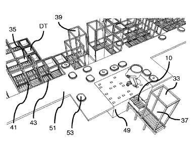
As shown in Figure 3a, the object storage handling and retrieval system of the
first
embodiment of the present invention further comprises a transfer system, the
transfer
system comprising a transfer station 49 on which items 28 frequently required
to be picked
in to delivery containers DT may be deposited. The transfer station 49 may
comprise some
form of table structure or receiving surface on to which items 28 may be
transferred from
successive storage containers 10 output via an additional output chute 37 from
the storage
and retrieval system 400. The transfer station 45 is located beneath the
storage and
retrieval system 400, an output port 33 of the storage and retrieval system
400 being
located such that robotic load handling devices 30 operative on the storage
and retrieval
system 400 may lower a required storage container 10 down to a holding
position adjacent
the transfer station 49 from where the items 28 contained therein maybe
picked, either
robotically or manually, on to the transfer station 49.
Whilst the transfer station 49 of the first embodiment of the invention is
described above
as a table-type structure or surface, it will be appreciated that the transfer
station 49 may
comprise a shelved-structure such as a VLM as fully described in patent
publication
number GB 2,524,383B1 (Ocado Innovation Limited).
As shown in Figures 3a and 3b, positioned between the transfer station 49 and
the pick
stations 35 is a track 51 on which a series of Autonomous Guided Vehicles
(AGVs) 53 run.
The track 51 links the transfer station 49 to an AGV position 55 located at
the or each pick
station 35 and within reach of the operative at the or each pick station 35.
The AGVs 53
comprise a vehicle having an item carrying portion disposed thereon. The AGVs
53 can
move under the control of the storage and retrieval system control utility
between the
transfer station 49 and the or each pick station 35. As shown in Figures 3a
and 3b, a
plurality of AGVs 53 may be in use at any one time.
CA 03104014 2020-12-16
WO 2019/243549 PCT/EP2019/066412
13
In use, as shown with reference to the schematic block diagram of the system
shown in
Figure 3c, a storage bin 10 is output from the storage and retrieval system
400 via the
output port 33 and the output chute 37. The storage bin 10 comprises items 28
required
to fulfil customer orders in the planned order horizon. The items 28 are
transferred by
suitable picking means, robotic 57 or manual, on to the transfer station 49.
It will be
appreciated that a number of items 28 are picked from the storage bin 10 on to
the transfer
station, the items 28 remaining on the transfer station 49 until required at
the or each pick
station 35 at which an order is to be picked requiring at least one of said
transferred items
28.
When the storage bin 10 is empty or when a predetermined number of items 28
have been
picked, the storage bin 10 is returned to the storage system 400 via the chute
37. It will
be appreciated that the storage bin 10 may be collected by a load handling
device 30
operative on the storage and retrieval system 400. However, it is possible
that the storage
bin 10 is returned to the storage system 400 via any other suitable means (not
shown).
Moreover, if the storage bin 10 contains no further items 28 to be stored the
empty storage
bin 10 may be returned to a storage bin filling station (not shown) in order
to be replenished
with items 28.
Items 28 now located on the transfer station 49 may be robotically or manually
removed
from the transfer station 49 and placed on AGVs 53. The AGVs comprising the
picked
items 28 are moved on the track 51 under the control of a suitably programmed
utility to
the AGV position 55 located at the or each pick station 35 requiring such an
item 35.
As can be seen in Figure 3c, items required in delivery containers DT may be
moved from
the storage and retrieval system 400 to pick stations via a number of means.
Firstly, a
storage bin comprising the item 28 may be moved to the storage bin side 41 of
the pick
station 35 via the load handling device 30 and the input chute 41' of the
storage bin side
41 of the pick station. Alternatively, as described above, the storage bin 10
comprising
the required items 28 may be output from the storage and retrieval system 400
via the
chute 37 to a point adjacent the transfer station 49 at which point the items
28 are
transferred to the transfer station 49 an on to individual AGVs. Individual
items 28 are then
transferred via the track 51 on AGVs 53 to the pick stations AGV location 55
from where
the item can be picked by the operative in to a delivery container DT in the
delivery
container side 41 of the pick station 35.
CA 03104014 2020-12-16
WO 2019/243549 PCT/EP2019/066412
14
It will further be appreciated that each pick station 35 may further comprise
a temporary
holding facility 47 in which the operative places individual items 28
delivered to the pick
station via any of the above described means required at a point in the item
planning
horizon but not required for a given delivery container DT located at that
instant in time at
the pick station 35.
Once a delivery container DT comprises all the items required for the given
customer order
or part thereof, the delivery container DT is returned to the storage and
retrieval system
400 for onward dispatch to the customer at the required time. It will be
appreciated that
the delivery container DT may be returned to a storage position within the
storage and
retrieval system 400 or may be transported directly to a dispatch area. In
either event, the
delivery container may be transported by a load handling device operative on
the storage
and retrieval system 400.
As described above and with reference to Figure 3c a pick station may be
supplied with
individual items for customer orders via storage bins 10 routed to the storage
side of the
pick station 35, or via AGVs 53 or via a combination of both of these routing
methods with
additional storage space being provided at the pick station in temporary
holding location
49.
Different possible routes of items 28 and storage bins 10 and delivery
containers DT are
represented by different forms of arrows in Figure 3c.
It will be appreciated that not all pick stations 35 in a given facility need
have all of the
options described above. For example, it may be possible for only half of the
pick stations
in any given facility to have AGV locations 55 and therefore some pick
stations 35 may
only be supplied via load handling devices 30 suppling storage bins 10 to the
storage bin
side 41 of the pick station 35. Furthermore, not all pick stations 35 may be
provided with
temporary holding locations 47. However, it will also be appreciated that
every pick station
in a given facility may be provided with all of the options described above
and
represented schematically in Figures 3a, 3b and 3c.
Figures 4a, 4b and 4c show a facility in which the pick stations 35 associated
with a given
storage and retrieval system 400 comprise all of the supply mechanisms
described above.
30 As can be seen in Figure 4b, a plurality of transfer stations 49 are
provided, linked by a
common track 51, the track 51 linking all the pick stations 35 in the
facility.
CA 03104014 2020-12-16
WO 2019/243549 PCT/EP2019/066412
In this way, items 28 required at pick stations 35 may be brought to any one
of the transfer
stations 49 as described above and picked robotically or manually on to AGVs
53 for
onward transmission to the AGV location 55 of any pick station 35. IT will be
appreciated
that in the case of robotically picking the items, each transfer station may
be provided with
5 a robotic picking device capable of picking a particular type of item 28.
For example one
transfer station 49 may be provided with a robotic picking arm capable of
picking heavy
items, one transfer station 49 may be provided with a robotic picking arm
capable of picking
bottles and a further transfer station 49 may be provided with a robotic
picking arm capable
of picking boxes. However, it will be appreciated that each robotic picking
arm may be
10 provided with means for picking any item of any weight, size or
configuration.
Additionally, it will be appreciated that the AGVs 53 may comprise any
suitable form of
AGV capable of carrying any of the items 28 required at the pick stations 35.
Each AGV
may be provided with means for carrying one or more items as required at any
given pick
station 35.
15 In this way, it will be appreciated that items 28 delivered to the
transfer system from the
storage and retrieval system 400 may be conveyed to the pick stations 35
independently
of the normal operation of the pick station 35, thereby providing an
additional supply of
items 28 to the pick station without requiring multiple additional load
handling device 30
movements in the storage and retrieval system 400.
Figures 5a and 5b show a further form of the invention in which the AGV 53 and
track 51
combination is replaced by a series of conveyors 57 carrying trays 59. The
transfer
stations 49 of the previous embodiments of the invention remain and the manner
in which
items are moved from storage bins 10 in the storage and retrieval system 400
on to the
transfer stations 49 is as previously described. However, once on the transfer
station 49,
.. the individual items 28 are transferred in to trays 59 located on the
conveyors 57. The
trays 59 are moved on the conveyors 57 to tray locations 55 located at the
pick stations
35.
The conveyor 57 may comprise any suitable form of conveyance means and may
include
but not be limited to, driven roller conveyor, high speed driven conveyor
means or
proprietary conveyor means such as ACOPOStrak TM conveyor or any other
suitable for
of conveyance means capable of carrying items 28 on trays 59 from transfer
stations 49
to pick stations 35.
CA 03104014 2020-12-16
WO 2019/243549 PCT/EP2019/066412
16
It will be appreciated that any given facility may comprise a combination of
all of the
systems described above. Furthermore, the facility may be adapted to be
entirely
automated using only robotic picking devices for transferring items from
storage bins 10 to
transfer stations 49 to secondary conveyance means such as a tray 59 conveyor
57
combination or on and off AGVs 53 to delivery containers DT or for
transferring items
directly from storage bins 10 to delivery containers DT at pick stations 35
whether using
temporary storage locations 47 or not.
Moreover, it will be appreciated that the use of secondary transfer means to
move items
from the storage and retrieval system 400 to the pick station 35 for picking
in to delivery
containers DT reduces the number of load handling device movements on the
storage and
retrieval system as a single storage bin 10 may be retrieved by a single load
handling
device 30 yet that storage bin may have all of the items 28 contained therein
removed and
accessible to every pick station 35 in the facility for a single load handling
device
movement.
It will be appreciated that the conveyance means of the invention may comprise
other
forms or conveyance devices such as for example but not limited to drones,
hovercraft and
other manual conveyance methods, for example coolies or other manual conveying
means. Furthermore, the AGVs or other forms of conveyance means may be of
different
types depending on the types of products to be conveyed.
In this way, the multiple methods of transferring items 28 in to delivery
containers DT
enable items 28 spread across a given facility pareto to be supplied to pick
stations 35
efficiently and in a timely manner, the method selected of transfer for any
given item being
managed according to the frequency and number of items 28 required for given
orders at
given pick stations 35.
Whilst the above embodiments are described with reference to a single-spaced
grid-based
storage and retrieval system, it will be appreciated that the invention may be
used in
association with any other form of grid¨based storage system storage and
retrieval system
such as Autostore TM in which the load handling devices occupy multiple grid
spaces on
the storage and retrieval system or a Knapp TM OSR shuttle and racking based
system or
any other form of storage and retrieval system having an output port from
which items 28
may be output.
CA 03104014 2020-12-16
WO 2019/243549 PCT/EP2019/066412
17
Furthermore, whilst the embodiments of the invention have been described with
reference
to items 28 to be picked for orders comprising multiple items, for example in
an online
grocery order fulfilment environment, it will be appreciated that the
invention may be used
in other forms of online retail and supply, such as general merchandise
fulfilment.
Moreover, the invention may be applied to storage and retrieval systems used
in other
fulfilment and sortation environments such as parcel sortation and delivery
and other
logistics fulfilment scenarios such as spare part supplies in a fabrication or
assembly
situation ¨ the term fulfilment to be interpreted broadly to include the
fulfilment of any item
requirement.