Note: Descriptions are shown in the official language in which they were submitted.
CAMERA CASING
Technical Field
[0001] Various aspects of this disclosure relate generally to a casing for
a camera,
particularly, a low temperature casing.
Background
[0002] Cameras generate their own heat with high shutter speed and
resolution settings.
However, when exposed to external elements such as cold temperatures, wind or
other weather
forces, the heat is dissipated into the external environment. The dissipation
of heat into the
environment decreases the performance of the camera, including, but not
limited to, that of
battery life.
[0003] The present description illustrates a casing that improves the
insulation of the camera
from cold external temperature, wind and/or weather and reduces the rate at
which generated
heat is dissipated into the external environment while allowing a user to
record and/or take
photos of the external environment from within the casing.
Summary
[0004] In an embodiment, a camera casing comprises at least one front face.
The front face
comprises a first opening, and is configured to securely fit with a camera. A
flexible covering is
attached to a perimeter of the front face, the covering having a service
opening to provide access
to an interior of the camera casing. The camera casing further includes a
first retaining member
arranged in the interior of the camera casing, the first retaining member
configured to secure the
1
Date Recue/Date Received 2022-07-06
camera to the front face. A material of the front face is different from a
material of the flexible
covering.
[0005] In another embodiment, a method of operating a camera casing is
provided. The
camera casing comprises at least one front face. The front face comprises a
first opening, and is
configured to securely fit with a camera. A flexible covering is attached to a
perimeter of the
front face, the covering having a service opening to provide access to an
interior cavity of the
camera casing. The camera casing further includes a first retaining member
arranged within the
interior cavity of the camera casing, the first retaining member configured to
bias the camera to
the front face and secure the camera within the camera casing. The method
comprises accessing
the interior cavity of the camera casing through the service opening,
inserting the camera into the
camera casing, aligning the camera with the front face, and securing the
camera to the front face
with at least the first retaining member.
[0006] In a further embodiment, a camera system comprises a camera and a
camera casing.
The camera casing comprises at least one front face. The front face includes
at least a first
opening, and is configured to securely fit with a camera. A flexible covering
is attached to a
perimeter of the front face, the covering having a service opening to provide
access to an interior
space of the camera casing. A first retaining member arranged and secured
within the interior
space of the camera casing, and the first retaining member configured to bias
the camera against
the front face to secure the camera within the casing.
Brief Description of the Drawings
[0007] In the drawings, like reference characters generally refer to the
same parts throughout
the different views. The drawings are not necessarily to scale, emphasis
instead generally being
2
Date Recue/Date Received 2022-07-06
placed upon illustrating the principles of the invention. In the following
description, various
embodiments of the invention are described with reference to the following
drawings, in which:
2a
Date Recue/Date Received 2022-07-06
FIG. lA shows a front perspective view of an embodiment of a casing;
FIG. 1B shows a rear perspective view of the embodiment of the casing of FIG.
1A;
FIG. 1C shows an embodiment of a rear perspective view of the interior of the
casing
shown in FIGS. 1A-1B;
FIG. 1D shows an embodiment of a rear perspective view of the interior of the
casing
shown in FIGS. 1A-1B;
FIG. lE shows an embodiment of a first retaining member of the casing of FIG.
1A;
FIG. 1F shows a side view of the embodiment of FIGS. 1A-1D with a camera;
FIG. 1G shows an embodiment of a perspective view of the embodiment of the
casing of
FIG. 1A;
FIG. 2A shows a front perspective view of an embodiment of a casing;
FIG. 2B shows a rear perspective view of the embodiment of the casing of FIG.
2A;
FIG. 2C shows a side view of the embodiment of the casing of FIGS. 2A-2B;
FIG. 3A shows a front perspective view of an embodiment of a casing;
FIG. 3B shows a side view of the embodiment of the casing of FIG. 3A;
FIG. 3C shows a side view of the embodiment of the casing of FIG. 3A;
FIG. 4 shows a schematic of an embodiment of the fitting between a front face
of casing
and a camera;
FIG. 5 shows a method of operating the casing; and
FIG. 6 shows a performance comparison chart of battery lifetime.
3
Date Recue/Date Received 2021-01-04
Description
[0008] The following detailed description refers to the accompanying
drawings that show, by
way of illustration, specific details and embodiments in which the invention
may be practiced.
[0009] The described invention provides insulation from cold weather
elements along with
improving protection from damage to the camera, by way of non-limiting
example, for
scratching on the front surface, or improved impact resistance.
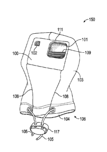
100101 FIG. lA provides a perspective view of an embodiment of a casing 150
for a camera
130 (illustrated in FIG. 1F) having a front face 100 and a covering 103,
covering 103 having at
least one service opening 104 to provide access to an interior 120
(illustrated in FIG. 1C and 1D)
of casing 150 for inserting at least camera 130 into casing 150.
[0011] The material of front face 100, shown in FIG. lA to be rectangular,
may be
configured as rigid, semi-rigid or flexible. In some embodiments, front face
100 is made from a
closed foam, such as Ethylene-Vinyl Acetate (EVA), or an open cell foam. In
other
embodiments, front face 100 may be configured as clear or transparent for
easier viewing. In an
embodiment, front face 100 is molded into a three-dimensional shape to have an
improved fit
with camera 130 where the features of camera 130 correspond to the three-
dimensional shape of
front face 100. This allows for easier positioning of camera 130, as opposed
to a completely
fabric casing that could slip loose or be difficult to position.
Alternatively, in a separate
embodiment, front face 100 is configured to be a flat surface such that front
face 100 is not a
molded surface. This embodiment allows for economical modification and
production during the
manufacturing process.
[0012] Although front face 100 is illustrated to be rectangular in FIG. 1A,
the shape of front
face 100 may be presented in many different conventional forms, sizes, shapes
and designs.
4
Date Recue/Date Received 2021-01-04
Front face 100 may be in a shape to fit a front of camera 130 or front face
100 may be larger or
smaller than the front of camera 130. Further, front face 100 may be square,
rectangular, circular,
oval shaped or a variety of other available shapes.
[0013] Front face 100 includes at least one opening or window, such as
first opening 101, to
align with a feature of camera 130, or for the feature of camera 130 to fit
through. Such feature
may be a lens 140 (illustrated in FIG. 1F) of camera 130. First opening 101
may be arranged in
any location on front face 100. In an alternative embodiment, first opening
101 is large enough
to provide access to a plurality of controls and displays on the front of
camera 130, and not only
lens 140. By way of a non-limiting example, lens 140 along with a display of
camera 130 may be
viewed through first opening 101. First opening 101 may be of various sizes
and shapes that
allow lens 140 of camera 130 to fit through it or align with it. In the
embodiment illustrated in
FIG. 1A, first opening 101, i.e. lens window, is presented as a rectangular
opening or space in
front face 100.
[0014] Additionally, front face 100 may have other openings, such as a
second opening 102,
provided to allow for accessibility and visibility to lights, displays,
buttons and other controls on
camera 130 from outside casing 150. In an embodiment, second opening 102 is
configured as a
display window, shown in FIG. lA as another opening or space in the upper left-
hand corner of
front face 100. However, second opening 102 may be arranged in any location on
front face 100.
Front face 100 offers a fit with camera 130 or lens 140 that locates the
feature on camera 130,
this allows other openings, such as second opening 102, to properly align with
various displays,
controls, and features on front, top, bottom, back or sides of camera 130 as
well as helps hold
camera 130 in place on front face 100 when it is jostled. Although only two
openings are
Date Recue/Date Received 2021-01-04
illustrated, there may be further openings on front face 100 to accommodate
other features on
camera 130.
[0015] Camera 130 may be presented in many different conventional forms,
sizes, shapes
and designs. Casing 150 and its various features can be designed to fit just
one type of camera or
many different types.
[0016] Covering 103, optionally made from a separate material than that of
front face 100, is
attached around a perimeter 111 of front face 100. Covering 103 is made from a
single piece or
multiple layers of a flexible material. Covering 103, in combination with
front face 100, acts as
a housing, or casing 150, for camera 130. The material of covering 103 and/or
front face 100
may be made from materials having improved thermal properties.
[0017] In the embodiment illustrated in FIG. 1A, covering 103 includes
service opening 104.
Although service opening 104 is illustrated to be located at abase 106 of
covering 103, it may be
located anywhere on covering 103. Service opening 104 is used to access
interior 120 (shown in
FIGS. 1C and 1D) of casing 150 for inserting camera 130 and/or one or more
additional
accessories 131 ((illustrated in FIG. 1F). Interior 120 of covering 103 may be
accessed with an
access mechanism 107 (shown in FIG. 1B), such as a zipper arranged on covering
103, or
alternatively, covering 103 is stretched such that casing 150 may even be
flipped inside out,
offering improved accessibility to camera 130 that is inside casing 150.
[0018] Optionally, as illustrated in FIG. 1A, at least one closure 105 is
provided in covering
103 around the perimeter of service opening 104 to allow for the closing of
the service opening
104. Closure 105 may be embodied as drawstrings, elastic gather, zippered
flap, zipper, button
straps, buttons or any one of a wide variety of other features or methods that
can partially or
6
Date Recue/Date Received 2021-01-04
completely close service opening 104. Inclusion of closure 105 provides
further security for
camera 130 within casing 150.
[0019] In a further embodiment, a locking mechanism 117, such as a cord
lock, may be
provided on closure 105 in order to prevent service opening 104 from
inadvertently opening,
providing further protection for camera 130 and/or one or more additional
accessories 131
arranged in covering 103 through service opening 104.
[0020] FIG. 1B illustrates a rear perspective view of casing 150. As
illustrated, covering 103
may include one or more access openings 119 to allow a user to view or
interact with various
controls, interfaces or displays on camera 130. As illustrated, access opening
119 may further
include access mechanism 107 for securing access opening 119. At least one
access opening 119
may be arranged anywhere in covering 103, but in the illustrated embodiment,
access opening
119 is arranged on a rear surface 112 of covering 103, or a side of covering
103 opposite front
face 100. Further access openings 119 may be provided to allow an extended
battery, battery
pack, or cord for charging from an external battery access to camera 130 that
is stored within
casing 150.
[0021] Access mechanism 107 may include a zipper, elastic gathers, buttons,
snaps,
drawstrings, flaps, VelcroTM flaps, latches, or any one of a wide variety of
other methods used
for opening and closing the various pockets, pouches, and other openings on
casing 150. Access
mechanism 107 is shown to extend from a first point 113 located at service
opening 104 to a
second point 114, illustrated at a midway point on rear surface 112 of
covering 103. However,
first point 113 and second point 114 may also be arranged in other locations
on covering 103 and
need not start or terminate at service opening 104. Access opening 119 may be
arranged on
covering 103 such that it is an opening independent from service opening 104.
Access
7
Date Recue/Date Received 2021-01-04
mechanism 107 is shown in FIG. 1B to be embodied as a zipper, in a zipped or
closed state, with
both sides of covering 103 being united in the back where access mechanism 107
is zipped
together. Although access mechanism 107 is not visible in FIG. 1A, it can also
be understood
that casing 150 of FIG. lA is also shown in a state with access mechanism 107
closed.
[0022] In an alternative embodiment, access opening 119 and access
mechanism 107 may be
omitted and a user may access the inside of casing 150 by either flipping
covering 103 inside out
or stretching the material.
[0023] Furthermore, in an embodiment, covering 103, as shown in FIG. 1A and
FIG 1B, is
constructed in a shape and design that resembles a hood, as in from a hooded
sweatshirt,
although covering 103 may be provided in any number of shapes sizes designs
constructions or
appearances and is not limited to that of a hood or hooded shape. Casing 150
of FIG. lA also
illustrates at least two hood seams 108 running diagonally from the bottom
corners of the front
face 100 to base 106 of covering 103. It can be understood that the hood seams
108, along with
the front face 100, have a resemblance to that of a hooded sweatshirt, or
persons face inside a
hooded sweatshirt, with the hood seams 108 resembling the brim of a hood and
neck down
toward the collar, and the front face 100 resembling a person's face nestled
inside the hood.
100241 FIGS. 1C-1D provides a rear perspective view of casing 150
illustrated with covering
103 flipped inside out to show interior 120 of casing 150. Furthermore, access
mechanism 107 is
shown in FIGS. 1C-1D in an unzipped state, allowing more room for covering 103
to be opened
and/or flipped inside out. Front face 100 is configured to hold camera 130 in
alignment with first
opening 101 with the use of either a retaining feature, such as a first
retaining member 109,
and/or from the fit created between camera 130, covering 103, and front face
100.
8
Date Recue/Date Received 2021-01-04
[0025] In the embodiments illustrated in FIG. 1C and 1D, front face 100 has
first retaining
member 109 attached in at least a first location 115 and a second location 116
on opposing sides
of front face 100. First location 115 and second location 116 may be arranged
directly on front
face 100 or adjacent to front face 100 on covering 103. Although first
location 115 and second
location 116 are arranged on the sides of front face 100, first location 115
and second location
116 may alternatively, or additionally, be arranged on the top and the bottom
of front face 100.
First retaining member 109 is shown in FIGS. 1C-1D as a stretchable band, such
as elastic, that
spans horizontally behind front face 100, creating a loop with front face 100,
where camera 130
can be held between front face 100 and first retaining member 109. It should
be understood that
first retaining member 109 may also be presented as at least one of a sleeve,
strap(s), loop(s),
snapping feature, VelcroTM strap, holding device, pouch, zippered pouch,
pocket or any one of a
wide variety of other shapes, sizes, forms, designs or constructions so long
as it is capable of
retaining camera 130 inside casing 150 and allowing lens 140 of camera 130 to
align with and/or
fit through first opening 101.
[0026] First retaining member 109 may be designed and arranged in a way so
not to obstruct
or block one or more camera features 132 (illustrated in FIG. 1F). Camera
features 132 may
include ports, buttons, or screens on the top, side and or the back of camera
130. In one
embodiment, illustrated in FIG. 1C, first retaining member 109 is configured
as two narrow
bands that wrap around the upper edge and the lower edge of the back of camera
130 such that a
Liquid Crystal Display (LCD) screen on the back of camera 130 is not blocked,
nor are ports or
camera features 132, on the sides of camera 130. In another embodiment,
illustrated in FIG. 1D,
first retaining member 109 may be configured with one or more cutouts 121 in
the side and/or
back of first retaining member 109. In an alternative embodiment, first
retaining member 109
9
Date Recue/Date Received 2021-01-04
may be made of a clear or transparent material such that a user may interact
with and/or view
camera features 132 through first retaining member 109.
[0027] In a further embodiment of casing 150, front face 100 is optionally
provided with at
least one second retaining member 110, illustrated in FIGS. 1C-1D as a strap,
which may be
attached directly to front face 100 or affixed to or incorporated into
covering 103 in at least two
locations on opposing sides, similar to the construction or arrangement of
first retaining member
109, to retain the one or more additional accessories 131 inside casing 150.
Additional
accessories 131 may include a heating element, an extended battery, battery
pack and/or cord for
charging from an external battery to camera 130 while camera 130 is inside
casing 150. In the
embodiment shown in FIGS. 1C-1D, opposing ends of second retaining member 110
is secured
to first location 115 and second location 116.
[0028] Second retaining member 110, as shown in FIG. 1C-1D, is embodied as
an elastic
band that spans horizontally behind first retaining member 109, creating a
loop with first
retaining member 109 where one or more additional accessories 131 may be held.
Second
retaining member 110 may be configured as a single band or as illustrated in
FIG. IC, a split
band such that a viewing window of camera 130 may be accessed and viewed. In
another
embodiment, illustrated in FIG. 1D, second retaining member 110 is embodied as
a single band
with one or more cutouts 121 that may be used as a viewing window. It should
be understood
that casing 150 may also be presented to include additional second retaining
members 110 such
as a sleeve, straps, loops, snapping feature, VelcroTM strap, holding strap,
pouch, zippered pouch,
pocket or any one of a wide variety of other shapes, sizes, forms, designs or
constructions, so
long as it is capable of retaining one or more additional accessories 131
within, or on, casing
150.
Date Recue/Date Received 2021-01-04
100291 Casing 150 may include a plurality of second retaining members 110
and each second
retaining member 110 may take different forms. By way of non-limiting example,
as illustrated
in FIGS. 1B and 1D, one second retaining member 110 may be a strap and another
second
retaining member 110 may be embodied as a pouch affixed or incorporated into
to the inside of
covering 103 that can retain extra batteries to keep them warm and/or hold a
battery that is
plugged into camera 130.
100301 As with first retaining member 109, second retaining member 110 may
also be
embodied as a clear or transparent material which would allow a user to view
or interact with
camera 130 through transparent, pressure sensitive material first retaining
member 109 and
second retaining member 110.
100311 One or more additional accessories 131, such as a heating element,
may be
considered to be any device or object capable of giving off heat and can be
provided in a wide
variety of conventional forms including, but not limited to: chemical heating
elements, electrical
heating elements, or fuel powered heating elements. Heating elements of a
certain shape, design,
or construction can be provided to fit inside casing 150, or alternatively,
heating elements of a
wide variety of shapes, designs, and constructions can fit inside. Heating
elements may be
provided with casing 150 or presented as a consumable. One such example of
heating elements
that may be used with casing 150 are chemical, oxygen activated packets that
are commonly
used for hand and foot warmers. Another example of heating elements is one or
more
rechargeable heating elements that may be inserted into casing 150 as
described above. An
embedded heating element 118 may also be permanently built or integrated into
casing 150.
Embedded heating element 118 may be sewn into covering 103 between layers or
in a pouch, as
illustrated in FIG. 1C. Additionally or alternatively, embedded heating
element 118 may also be
11
Date Recue/Date Received 2021-01-04
sewn into first retaining member 109 and/or second retaining member 110, as
illustrated in FIG.
1D.
[0032] FIG. 1E illustrates an alternative embodiment illustrating first
retaining member 109
and front face 100. In the illustrated embodiment, second retaining member
110, as described in
other embodiments, is incorporated together with first retaining member 109 as
a single feature
or component. By way of a non-limiting example, first retaining member 109 may
be embodied
as a folded over band, where additional accessories 131 may be held within a
fold 123 of first
retaining member 109. Alternatively, first retaining member 109 may include a
secured pouch to
contain additional accessories 131.
[0033] In an alternative embodiment, in lieu of second retaining member
110, one or more
additional accessories 131 may be retained by covering 103 itself. In this and
other alternative
embodiments, closure 105, for partially or completely closing service opening
104, may be
provided to improve the retention of not only camera 130 but also the
additional accessories 131
inside covering 103.
[0034] FIG. 1F illustrates a side view of casing 150, as described with
FIGS. 1A-1E with
camera 130 inserted between front face 100 and first retaining member 109.
Lens 140 of camera
130 is arranged through first opening 101 of front face 100. First retaining
member 109 is shown
to be stretched around camera 130 securing camera 130 to front face 100.
Further, additional
accessories 131 are shown to be inserted between first retaining member 109
and second
retaining member 110. Second retaining member 110 is stretched around
additional accessories
131 securing additional accessories 131 against first retaining member 109. In
the illustrated
embodiment, closure 105 is shown to substantially close service opening 104,
further securing
camera 130 and additional accessories 131 within casing 150.
12
Date Recue/Date Received 2021-01-04
[0035] Camera features 132, such as displays, buttons and/or controls,
arranged on top,
bottom, back or sides of camera 130 may be accessed by pushing through
covering 103 to apply
pressure to controls, or stretching covering 103 sufficiently to access camera
features 132.
[0036] With covering 103 pulled over camera 130, casing 150 may reduce the
rate of heat
that dissipates out into the natural external environment, both from
supplementary heating
sources and from camera 130 itself, and thus provide insulation from cold
external temperatures
and weather. Casing 150 may also help trap heat inside that is generated
either from camera 130
itself, or from the heating elements that can optionally be packed inside. The
ability to provide
improved insulation and heat retention within casing 150 can extend battery
life and
functionality of camera 130by reducing its exposure to cold temperatures which
can have an
adverse effect on battery life and performance.
[0037] FIG. 1G illustrates a perspective view of an alternative embodiment
of interior of
casing 150 shown in FIG. 1A which uses a tightly fitting covering 103 to aid
in holding camera
130 in place. Covering 103 may be constructed in such a way that covering 103
itself functions
as first retaining member 109. The fit of camera 130 within casing 150 acts to
hold camera 130
within casing 150. Covering 103 may be configured such that it fits tightly
around camera 130
holding camera 130 tightly against front face 100. Further, first retaining
member 109 may be
configured as an opening in a lining 122 of covering 103 such that lining 122
fits tightly around
camera 130. Additional accessories 131 may be included within covering 103
between lining 122
in an opening on the side of the lining 122 opposite camera 130, which may be
considered as
second retaining member 110. Thus, lining 122 is arranged to separate first
retaining member
109 and second retaining members 110 within casing 150. Further, such casing
may take the
13
Date Recue/Date Received 2021-01-04
appearance of a stuffed animal or toy. Many other appearances, designs, and
constructions can
also be presented.
[0038] In the embodiment illustrated in FIG. 1A-1G casing 150 is designed
to look like a
hood, as from a hooded sweatshirt, with front face 100 resembling the opening
for a face, or a
human face and covering 103 resembling a hood surrounding the face and keeping
it warm.
Casing 150 could also be made smaller, having a tighter fit with camera 130 to
be loaded inside.
[0039] FIG. 2A provides a perspective view of another embodiment
illustrating a casing 250
that is designed in such a way to look like a stuffed toy resembling a bear or
animal, although it
can be offered in any number of shapes, sizes, designs, constructions, or
appearances. Front face
100 and first opening 101 are presented in this embodiment of casing 250 of
FIG. 2A-2C in a
similar fashion to other embodiments already described.
[0040] Covering 203, illustrated in FIG. 2A, is attached around perimeter
111 of front face
100. In this embodiment, covering 203 is shaped to look like an animal face.
Covering 203 is
sewn and stuffed with cotton, batting, or other materials to give it different
shapes, but also
provide a secure and tight fit for camera 130, and optionally any additional
accessories 131, such
as a heating element (as illustrated in FIG. 2C). In this embodiment, covering
203 is designed
and stuffed in a way to resemble an animal, having two animal ears 208
incorporated at the top
in two places. Other features may also be included to change or enhance the
appearance in a
wide variety of different ways. In an alternative embodiment of casing 250,
covering 203 does
not include stuffing but instead is configured with a fit that is tight around
camera 130 and the
tight fit aids in holding camera 130 within casing 250.
[0041] FIG. 2B provides a rear perspective view of casing 250. This
embodiment of casing
250 shows that there is a first retaining member 209 incorporated in covering
203 that fits
14
Date Recue/Date Received 2021-01-04
camera 130 inside (illustrated in FIG. 2C). First retaining member 209 aids in
holding camera
130 in place on the front face 100 and allows lens 140 to align with first
opening 101. In the
illustrated embodiment, first retaining member 209 is presented as a pouch for
retaining camera
130 inside an interior 220 of covering 203. A service opening 204 arranged at
a bottom 206 of
covering 203 is opened for the loading or unloading of camera 130 into first
retaining member
209. Service opening 204 may also be utilized for mounting camera 130, which
has been
arranged in casing 250, to an external mount or selfie stick attached to the
base of camera 130.
[0042] It should be understood that first retaining member 209 may be
provided in many
different shapes, sizes, forms, designs, or constructions so long as it is
capable of retaining
camera 130 in interior 220 of casing 250 and allowing lens 140 of camera 130
to align with, or
fit through, first opening 101.
[0043] In a further embodiment, covering 203 may also include a closure 205
for completely,
or partially, closing service opening 204, or the illustrated open bottom, of
casing 250. Closure
205 may include elastic gather, drawstring, zipper, zippered flap, flaps,
straps or any one of a
wide variety of other methods or features for improving the retention of
camera 130 within
casing 250
100441 In a further embodiment of FIG. 2B, casing 250 also optionally
includes a second
retaining member 210 incorporated in any location on or in covering 203.
Second retaining
member 210 is able to hold one or more additional accessories 131, such as a
heating element,
and is presented as a separate pocket from first retaining member 209. Second
retaining member
210 may include one or more openings 219 arranged on the exterior of casing
250 or the interior
of casing 250. Opening 219 is secured using a fastener 207, shown in FIG. 2B
as a zipper in an
open, unzipped state. When open, fastener 207 offers access to second
retaining member 210.
Date Recue/Date Received 2021-01-04
When fastener 207 is closed, it retains additional accessories 131 within
second retaining
member 210. A plurality of opening 219 may be provided that allow an extended
battery, battery
pack, or cord for charging from an external battery to be attached to camera
130 that is stored
within casing 250. Although opening 219 is shown to be arranged on the
exterior of casing 250,
opening 219 may also be arranged within covering 203 and accessed through
service opening
204.
[0045] Although fastener 207 is shown as a zipper in FIG. 2B, fastener 207
may also be
comprised of elastic gathers, buttons, snaps, drawstrings, flaps, VelcroTM
flaps, latches, or any
one of a wide variety of other methods for opening and closing the various
pockets, pouches, and
other openings on casing 250. It should be understood that second retaining
member 210 may be
provided in many different shapes, sizes, forms, designs, or construction so
long as it is capable
of retaining one or more additional accessories 131, such as a heating
element, within, or on,
casing 250. In the embodiment illustrated in FIG. 2A-2B, camera 130 and
additional accessories
131 are in separate retaining areas.
[0046] In an alternative embodiment, first retaining member 209 is arranged
in covering 203
such that first retaining member 209 holds camera 130 along with additional
accessories 131,
such as heating element. Thus, camera 130 and additional accessories 131 are
retained in the
same area.
[0047] FIG. 2C illustrates a side view of casing 250 with camera 130
inserted into interior
220 of covering 203 in first retaining member 209, embodied as a pouch or a
compaitment, such
that it is fitted with front face 100. Stuffing of covering 203 aids in
holding camera 130 to front
face 100 and maintaining a tight fit against front face 100. Lens 140 is
arranged through first
opening 101 of front face 100. Further, additional accessories 131 is shown to
be arranged in
16
Date Recue/Date Received 2021-01-04
second retaining member 210, illustrated as a pouch or compartment in covering
203. In the
illustrated embodiment camera 130 and additional accessories 131 are separated
by different
retaining members. However, in an alternative embodiment, camera 130 and
additional
accessories 131 may share first retaining member 209.
[0048] In another embodiment, illustrated in FIGS. 3A-3C, a casing 350 is
configured to
have a plurality of front faces. FIG. 3A shows a perspective view of casing
350 having a first
front face 100a and a second front face 100b. Each front face 100a, 100b may
include all of the
features of front face 100, shown and described in earlier embodiments,
including at least a first
opening 101a on first front face 100a and a first opening 101b on second front
face 100b. This
arrangement of at least two front faces 100a, 100b is advantageous for use
with a camera 330
(illustrated in FIG. 3C). Camera 330 may be embodied with a plurality of
lenses 340a, 340b.
[0049] Each front face 100a, 100b is arranged on opposite sides of a
covering 303. Covering
303 may include all of the features shown and described in earlier
embodiments. In FIG. 3A-3C
covering 303 is shown to be attached around a perimeter 111a, 111b of each
front face 100a,
100b. Camera 330 is arranged between each front face 100a, 100b by using a
first retaining
member 309. In the illustrated embodiment, first retaining member 309 is a
tension applying
element arranged on a first side 307 and/or a second side 308 between each
front face 100a, 100b
in an interior 320 of covering 303 and/or incorporated within the covering
303. First retaining
member 309 pulls first front face 100a and second front face 100b towards each
other. Thus,
when camera 330 is placed between each front face 100a, 100b camera 330 is
held in place, not
only by the fitting of each front face 100a, 100b with a feature of camera
330, such as lenses
340a, 340b through at least first openings 101a, 101b, but also the tension
placed on camera 330
from first retaining member 309 pulling each front face 100a, 100b together.
17
Date Recue/Date Received 2021-01-04
100501 Optionally, one or more second retaining member 310 may be included
in casing 350.
Second retaining member 310 may be configured as any of the above-mentioned
embodiments
arranged on or in covering 303. In the illustrated embodiment, one or more
second retaining
member 310 is arranged below each front face 100a, 100b and configured as a
pouch for holding
additional accessories 131 (illustrated in FIG. 3C) such as heat packs,
batteries or other
accessories mentioned with other embodiments. Second retaining member 310 may
be accessed
through an optional one or more access feature 319, illustrated as a flap in
FIG. 3A. Access
feature 319 offers access to interior 320 of casing 350. Additionally or
alternatively, at least one
access feature 319 offers access to second retaining member 310. Additionally
or alternatively,
access feature 319 may be embodied similar to access opening 119 and access
mechanism 107.
100511 FIG. 3B illustrates a side view of casing 350. Interior 320 of
casing 350 is prepared
for inserting camera 330 by separating front faces 100a, 100b such that first
retaining member
309 and covering 303 are stretched, as illustrated by the arrows. In a relaxed
state, or covering
303 being in an unstretched state, the space between each front face 100a,
100b is less than the
width of camera 330. When preparing casing 350 for camera 330, covering 303 is
stretched such
that the space between each front face 100a, 100b is greater than the width of
camera 330 to
allow for insertion of camera 330.
100521 FIG. 3C illustrates a side view of casing 350 with camera 330
inserted into casing
350. Camera 330 is configured to be inserted at a base 306 through a service
opening 304 and
held in place by a combination of each lens 340a, 340b being aligned with each
of the first
opening 101a, 101b. Tension from front faces 100a, 100b applied on either side
of camera 330 at
least partially holds camera 330 in place. The space between each front face
100a, 100b with
loaded camera 330 is substantially similar to the width of camera 330.
18
Date Recue/Date Received 2021-01-04
[0053] In a further embodiment, a closure 305 may be provided to further
secure camera 330
within casing 350. Closure 305 may be similar to closure 105 described with
the embodiment
illustrated in FIGS. 1A-1D and 1F. Closure 305 may be further for securing
camera 330 within
casing 350 by at least partially closing service opening 304 preventing camera
330 from being
inadvertently removed from casing 350.
[0054] FIG. 4 illustrates a top view schematic of one embodiment of the fit
between camera
130 and front face 100 having a snap fit. Front face 100 includes a snapping
feature 410 arranged
on opposite sides of front face 100 that snaps or holds camera 130 into place
against front face
100, securing camera 130 in position. Snapping feature 410 may be arranged on
the sides of
front face 100, as illustrated, and/or at the top and bottom of front face 100
such that snapping
feature 410 may be arranged on two sides of front face 100 or around the
perimeter of front face
100, i.e. four sides. Snapping feature 410 may be configured to extend up to
the rear portion of
camera 130.
[0055] In the illustrated embodiments, camera 130, 330 is held in place
within casing 150,
250, 350 by at least one of: the direct fit between front face 100, 100a, 100b
and camera 130,
330; the fit of casing 150, 250, 350 with camera 130, 330; first retaining
member 109, 209, 309
fitting camera 130, 330 against front face 100; and closure 105, 205, 305 at
least partially
enclosing camera 130, 330 within casing 150, 250, 350.
[0056] FIG. 5 illustrates an embodiment for operating 500 casing 150, 250,
350. First 510, a
user accesses interior 120, 220, 320 of casing 150, 250, 350 by opening
service opening 104,
204, 304. The size of service opening 104, 204, 304 is increased allowing the
user to open
covering 103, 203, 303 and/or covering 103 is flipped partially or entirely
inside out. The ability
to open covering 103, 203, 303, or flip covering 103 inside out allows the
user easier access to
19
Date Recue/Date Received 2021-01-04
load camera 130, 330 inside casing 150, 250, 350. Furthermore, the user has
easier access to
camera features 132, such as controls, displays, and features, which may be
located on the top,
sides, bottom and back of camera 130, 330.
[0057] Second 520, insert camera 130, 330 into casing 150, 250, 350 through
service
opening 104, 204, 304.
[0058] Third 530, align a feature of camera 130, 330, such as lens 140,
340a, 340b, with, or
fit through, first opening 101, 101a, 101b. In an embodiment, first opening
101, 101a, 101b is
configured to fit, even snap, in place with lens 140, 340a, 340b. A fit may
exist between lens
140, 340a, 340b and first opening 101, 101a, 101b to hold camera 130, 330 in
place, reducing the
likelihood of camera 130, 330 jarring loose from casing 150, 250, 350, front
face 100, 100a,
100b and/or first opening 101, 101a, 101b when camera 130, 330 is jostied or
jerked. The fit
between lens 140, 340a, 340b and first opening 101, 101a, 101b may also align
front face 100,
100a, 100b with camera 130, 330. The locating of front face 100, 100a, 100b in
relation to
camera 130, 330 also helps to align second opening 102 with one or more
controls, displays and
features on the front of camera 130, 330. This allows the user to view or
interact with any of the
controls, displays, and features that second opening 102 is aligned with.
[0059] Fourth 540, secure camera 130, 330 to front face 100, 100a, 100b
using at least first
retaining member 109, 209, 309. First retaining member 109, 209, 309 may hold
camera 130,
330 to front face 100, 100a, 100b alone or work in conjunction with the fit
from front face 100,
100a, 100b.
[0060] Fifth 550, load any desired additional accessories 131 into casing
150, 250, 350, such
as a heating element. As discussed in various embodiments, a user who wishes
to load additional
accessories 131 into casing 150, 250, 350 may secure additional accessories
131 in casing 150,
Date Recue/Date Received 2021-01-04
250, 350 using at least one second retaining member 110, 210, 310 or by
loading additional
accessories in covering 103, 203, 303.
[0061] Sixth 560, close covering 103, 203, 303 and/or flip covering 103
back over camera
130 and optionally fasten service opening 104, 204, 304 using closure 105,
205, 305. With
service opening 104, 204, 304 fastened, it can be understood that camera 130,
330 stored within
would be partially or completely covered by covering 103, 203, 303 and front
face 100, 100a,
100b, offering protection and insulation for camera 130, 330.
[0062] Optionally mounting camera 130, 330 to a mount or a selfie stick
through service
opening 104, 204, 304. Closure 105, 205, 305 may be secured around the mount.
[0063] It can be understood that heat is generated inside casing 150, 250,
350 from the work
being performed by the camera's internal electronics and batteries, and/or
from one or more
heating elements loaded inside. It can also be understood that casing 150,
250, 350 insulates
camera 130, 330 from cold outside temperatures while also reducing the rate at
which heat is
dissipated from the inside of casing 150, 250, 350 into the external
environment.
[0064] The ability to retain heat within casing 150, 250, 350, as well as
insulate camera 130,
330 from cold outside temperatures, is beneficial since sustained exposure to
cold temperatures
reduces battery functionality and life. Thus, casing 150, 250, 350 improves
camera 130, 330
performance and battery life of camera 130, 330 stored within.
100651 Additionally, while camera 130, 330 is sheltered inside casing 150,
250, 350 it is still
able to record video and take photos of events happening in the external
environment since lens
140, 340a, 340b of camera 130, 330 aligns with, or fits through, first opening
101, 101a, 101b.
Furthermore, a user may also interact with camera features 132, such as other
buttons and
controls, located on the back, top, bottom, and sides of camera 130, 330 by
pushing through the
21
Date Recue/Date Received 2021-01-04
flexible material of covering 103, 203, 303. Commonly, the record button or
power button is
located on the top or sides of camera 130, 330 and the user may interact with
these buttons, or
camera feature 132, by pushing them from the outside of casing 150, 250, 350.
[0066] Battery life of camera 130, 330 enclosed in casing 150, 250, 350 has
been shown to
be improved with or without additional heating sources. Camera 130, 330
generates its own heat
with features such as a high shutter speed and resolution settings. Heat
generated from camera
130, 330 may be held within casing 150, 250, 350 creating a more temperature
suitable
environment for battery life performance. In some situations, the battery life
has been shown to
double.
[0067] FIG. 6 shows a performance chart 600 comparison of a camera with the
above-
described casing versus a camera without the casing. A test was performed with
a camera where
the battery was no less than 98% charged. The camera was turned on, set to the
correct settings,
and the record button on the camera was pushed. As soon as the camera began
recording, the
camera was placed into a freezer, kept at or below 0 Fahrenheit, to simulate
cold temperatures.
Further, a fan within the freezer was used to simulate windchill, moving hot
ambient air away
from the camera, cooling the camera further. The camera was left in the
freezer, recording
continuously until the battery died and the camera shut off. Afterwards, the
recording was
evaluated for the total time that the camera was able to film. The testing was
performed without
an external heating source for the camera and the heat generated was from the
camera itself.
[0068] In a first experiment 610, the camera was set to 960 resolution, 120
frames per second
(fps) and a wide view. As shown, the average recording time without a casing
was 35 min but
with the casing was 83 min. The camera with the casing showed a 235%
improvement in the
function of the camera over the camera without the casing.
22
Date Recue/Date Received 2021-01-04
[0069] In a second experiment 620, the camera was set to 1440 resolution,
60 fps and a wide
view. As shown, the average recording time without a casing was 38 min but
with the casing was
85 min. The camera with the casing showed a 221% improvement over the camera
without the
casing.
[0070] In a third experiment 630, the camera was set to 2700 resolution, 30
fps and a wide
view. As shown, the average recording time without a casing was 49 min but
with the casing was
86 min. The camera with the casing showed a 175% improvement over the camera
without the
casing.
[0071] In a fourth experiment 640, the camera was set to 4000 resolution,
30 fps and a wide
view. As shown, the average recording time without a casing was 34 min but
with the casing was
70 min. The camera with the casing showed a 205% improvement over the camera
without the
casing.
[0072] It is thus shown that a camera arranged within casing 150, 250, 350
improves the
performance of the camera and the battery in cold temperatures.
[0073] In a separate test, a camera battery was charged no less than 98%
charged. The
camera was placed in the freezer for an amount of time and the temperature
maintained at or
below 1 Fahrenheit. This amount of time was predetermined and is referred to
as the "cold start
time" period. A fan was also placed in the freezer and was set to either an
"on" or an "off" mode
when during the cold start time. After the cold start time had passed, the
camera was turned on,
set to the correct setting and the record button was pushed. As soon as the
camera began
recording, it was again placed in the freezer. The camera was left in the
freezer, recording
continuously, until the battery died and the camera shut off. Afterwards, the
recording was
evaluated to obtain the total time the camera was filmed for, or the
"runtime".
23
Date Recue/Date Received 2021-01-04
[0074] The camera was tested with the casing as described in the
embodiments and without
the casing. For tests with the casing, two hand warmer sized chemically
activated heat packs
arranged within the casing, as described in certain embodiments. The packs
were fully activated
before beginning the testing period. For tests without the casing, no heating
elements were used.
If the camera failed to start at all after the cold start time, it was
considered to have failed the
test. If the camera started and ran for any amount of time it was considered
to have passed.
[0075] The camera settings were set to 4000 resolution, 30 fps and a wide
view. In the tests
without a casing, the camera failed in cold start times greater than 30 min
when the fan in the
freezer was in the "off' mode. When the fan was in the "on" mode, the camera
was unable to
turn on after being in the freezer for 30 min. However, with the casing and
heat packs, not only
was the camera able to turn on after 60 min in the freezer, with the fan both
in the "on" and "off"
mode, but it ran for at least 72 min. Thus, combination of the camera being
arranged within the
casing along with heating elements was shown to have better performance than a
camera without
heating elements or a casing.
[0076] While the invention has been particularly shown and described with
reference to
specific embodiments, it should be understood by those skilled in the art that
various changes in
form and detail may be made therein without departing from the spirit and
scope of the invention
as defined by the appended claims. The scope of the invention is thus
indicated by the appended
claims and all changes which come within the meaning and range of equivalency
of the claims
are therefore intended to be embraced.
24
Date Recue/Date Received 2021-01-04