Note: Descriptions are shown in the official language in which they were submitted.
CA 03105380 2020-12-29
SYSTEMS AND METHODS FOR GENERATING AND CONSUMING POWER
FROM NATURAL GAS
BACKGROUND
This specification relates to enabling the utilization of raw natural gas,
such as flare gas,
stranded gas, and associated gas for power generation. More specifically, the
specification relates to on-site generation of electricity from natural gas to
power
modular processing units adapted to perform distributed computing tasks.
Extracting oil from unconventional resources, such as shale gas formations,
through the
combination of horizontal drilling and hydraulic fracturing has increased at a
rapid pace
in recent years. The Bakken, Powder River Basin, Denver Julesburg ("D-J")
Basin,
North Park Basin, and Permian Basin are just some of the important "plays" in
the
United States. A "play" is the geographic area underlain by a gas- or oil-
containing
geologic formation.
Development of these gas plays and other unconventional resources presents
significant potential for economic development and energy independence, but
also
presents the potential for environmental impacts on land, water and air. For
example,
although oil production represents the most important source of revenue for a
given
well, most wells also produce natural gas as a low-value byproduct.
Unfortunately, the
liquids-rich natural gas byproduct often cannot be economically transported by
trucks or
trains from remote well locations. Although such natural gases could be
transported via
pipelines, many oil and natural gas wells are located beyond the reach of such
infrastructure. Absent gas pipeline infrastructure, oil well operators must
either "vent" or
"flare" produced gasses for safety reasons. Venting is the controlled release
of natural
gases into the atmosphere in the course of oil and gas production operations,
however
natural gas accumulations around the wellbore create significant safety
hazards. Flaring
is the controlled burning of natural gas produced in association with oil in
the course of
routine oil and gas production operations, and is designed to minimize the
safety and
environmental risks associated with venting uncombusted natural gas.
1
Date Recue/Date Received 2020-12-29
CA 03105380 2020-12-29
As of April 2016, the NOAA estimates that there are over 6,200 individual
flares in the
United States, which burn about 35 billion ft3 of natural gas annually¨enough
to supply
about 6 million homes. Such large-scale flaring of natural gas has raised
serious
environmental and health concerns and various state and federal regulators
have begun
to take action by implementing strict regulations and enforcement policies.
For example,
Colorado generally limits flaring to 60 days and many new well permits require
producers to have a natural gas off-take solution prior to production; North
Dakota has
recently implemented a requirement that 90% of associated gas be captured by
2020;
and Texas only allows new wells to flare for 10 days before an additional 45-
day permit
must be obtained. The EPA has also implemented flaring regulations where sites
that
exceed 100 tons per year of VOC, CO or NOX trigger Title V "Major Source
Emitter"
rules. Violations of state or federal rules can result in oil wells being
"shut in," rejected
permits and/or significant cash fines.
Stranded natural gas, particularly in the case where liquids-weighted wells
are shut in
due to gas takeaway constraints, represents a very low-cost power generation
opportunity. Stranded gas exists across most prominent shale fields today
including in
the D-J Basin, Permian Basin, Bakken, SCOOP/STACK, etc. Many oil and gas
operators in pipeline-constrained environments readily offer their natural gas
for low
cost¨even at a loss to the operator in some cases¨so that they can produce
oil, which
often represents the vast majority of a well's lifetime economics.
One potential solution to the natural gas problem lies in distributed
computing.
Cryptocurrency is a booming asset class with the combined market
capitalization of
digital currencies surpassing $380 billion in July 2018. Cryptocurrencies
operate on a
distributed system of computers "mining" the currencies ¨ essentially
processing the
underlying algorithms to continuously verify transactions and account
balances. The
crypt mining process is a significant industry in its own right, projected to
reach a value
of $39 billion by 2025 with a projected CAGR of 29.7%.
This high-growth industry requires innovative and inexpensive electricity
sources as it
requires enormous amounts of power¨approximately 29 TWh of electricity per
year on
2
Date Recue/Date Received 2020-12-29
CA 03105380 2020-12-29
a global basis. For perspective, cryptocurrency mining consumes more power
annually
than 159 countries, including Hungary, Ireland, Nigeria or Slovakia. Indeed,
electricity is
typically the single largest lifetime cost to a cryptocurrency mining
operation, with power
costs offsetting approximately 30% of total mining revenues in the US.
Accordingly, there remains a need for systems and methods for generating
electricity
from natural gas produced from oil wells. It would be beneficial if such
electricity could
be produced and consumed on-site, for example, by using it to operate power-
intensive,
modular processing units. It would be further beneficial if such processing
units could be
employed to mine cryptocurrency or perform other distributed computing tasks
to
generate additional revenue.
SUMMARY
In accordance with the foregoing objectives and others, exemplary systems and
methods are disclosed herein to convert raw natural gas into a fuel gas stream
that may
be used to power any number of on-site power generation modules. In turn, the
power
generation modules may convert the fuel gas stream into electricity, which may
be
employed to power any number of modular distributed computing units. In
certain
embodiments, the distributed computing units may be adapted to mine
cryptocurrency
or perform other distributed computing tasks to generate revenue.
In one embodiment, a flare mitigation system is provided. Such system may
include an
electrical power generation system, which may include a power generation
module
adapted to: receive a fuel gas stream, such as a fuel gas associated with a
heat value
of at least about 1,000 Btu/scf; and consume the fuel gas stream to generate a
high-
voltage electrical output associated with a first voltage. The electrical
power generation
system may also include an electrical transformation module in electrical
communication with the power generation module, the electrical transformation
module
adapted to: receive the high-voltage electrical output generated by the power
generation
module; and transform the high-voltage electrical output into a low-voltage
electrical
output associated with a second voltage that is lower than the first voltage.
3
Date Recue/Date Received 2020-12-29
CA 03105380 2020-12-29
The flare mitigation system may also include a distributed computing system
powered
by the electrical power generation system. The distributed computing system
may
include a communications system with one or more data satellite antennas in
order to
provide a network; and a first mobile data center. The mobile data center may
include
an enclosure defining an interior space; a plurality of distributed computing
units located
within the interior space of the enclosure, each of the plurality of
distributed computing
units in communication with the network; and a power system located at least
partially
within the interior space of the enclosure, the power system in electrical
communication
with the electrical transformation module and the plurality of distributed
computing units
such that the power system receives the low-voltage electrical output and
powers each
of the plurality of distributed computing units.
In some cases, the power generation module may be an engine-type generator
that
generates a high-voltage electrical output of from about 70 kW to about 2 MW
(e.g.,
from about 70 kW to about 300 kW, from about 300 kW to about 400 kW, 400 kW to
about 1 MW, or from about 1 MW to about 2 MW). The first voltage of the high-
voltage
electrical output may be from about 480 V to about 4.16 kV. And the second
voltage of
the low-voltage electrical output may be from about 208 V to about 240 V.
In other cases, the power generation module may be a turbine-type generator
that
generates a high-voltage electrical output of from about 2 MW to about 30 MW.
In such
cases, the first voltage of the high-voltage electrical output may be from
about 4.16 kV
to about 12 kV. And the second voltage of the low-voltage electrical output
may be from
about 208 V to about 240 V.
In another embodiment, a flare mitigation system is provided. The system may
include
an electrical power generation system having a first power generation module
and a
second power generation module. The first power generation module may be
adapted
to receive a first fuel gas stream, such as a fuel gas associated with a heat
value of at
least about 1,000 Btu/scf, and to consume the fuel gas stream to generate a
first high-
voltage electrical output associated with a first voltage. The second power
generation
module may be adapted to receive a second fuel gas stream including the fuel
gas, and
4
Date Recue/Date Received 2020-12-29
CA 03105380 2020-12-29
to consume the second fuel gas stream to generate a second high-voltage
electrical
output associated with the first voltage.
The electrical power generation system may also include a parallel panel in
electrical
communication with the first power generation module and the second power
generation module. The parallel panel may be adapted to receive the first and
second
high-voltage electrical outputs; and combine and/or synchronize the first and
second
high-voltage electrical outputs into a combined high-voltage electrical
output.
The electrical power generation system may also include an electrical
transformation
module in electrical communication with the parallel panel. The electrical
transformation
module may be adapted to receive the combined high-voltage electrical output;
and
transform the combined high-voltage electrical output into a low-voltage
electrical output
associated with a second voltage that is lower than the first voltage.
The flare mitigation system may further include a distributed computing system
powered
by the electrical power generation system. The distributed computing system
may
include a communications system having one or more data satellite antennas in
order to
provide a network. Moreover, the distributed computing system may include a
first
mobile data center having an enclosure defining an interior space; a plurality
of
distributed computing units located within the interior space of the
enclosure, each of
the plurality of distributed computing units in communication with the
network; and a
power system located at least partially within the interior space of the
enclosure, the
power system in electrical communication with the electrical transformation
module and
the plurality of distributed computing units such that the power system
receives the low-
voltage electrical output and powers each of the plurality of distributed
computing units.
The details of one or more embodiments of the subject matter of this
specification are
set forth in the accompanying drawings and the description below. Other
features,
aspects, and advantages of the subject matter will become apparent from the
description, the drawings, and the claims.
5
Date Recue/Date Received 2020-12-29
CA 03105380 2020-12-29
BRIEF DESCRIPTION OF THE DRAWINGS
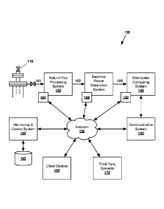
FIG. 1 shows an exemplary flare mitigation system 100 according to an
embodiment.
FIG. 2 shows an exemplary natural gas processing system 200 according to an
embodiment.
FIG. 3 shows an exemplary electrical power generation system 300 comprising a
power
generation module 331 in electrical communication with an electrical
transformation
module 335.
FIG. 4 shows another exemplary electrical power generation system 400
comprising a
plurality of power generation modules (431a, 431b) in electrical communication
with an
electrical transformation module 435 via a parallel panel 460.
FIG. 5 shows an exemplary distributed computing system 500 according to an
embodiment.
FIG. 6 shows an exemplary computing machine 600 and modules 650 according to
an
embodiment.
DETAILED DESCRIPTION
System Overview
Referring to FIG. 1, an exemplary flare mitigation system 100 according to an
embodiment is illustrated. As shown, the system 100 may comprise a natural gas
processing system 120, an electrical power generation system 130, a
distributed
computing system 140, a communication system 155 and a monitoring and control
system 180.
In one embodiment, the flare mitigation system 100 may comprise a natural gas
processing system 120 adapted to receive a raw natural gas stream 101 from one
or
more wellheads 110 in an oil and/or gas reservoir. The natural gas processing
system
120 is generally adapted to convert the received raw natural gas 101 into a
fuel gas
6
Date Recue/Date Received 2020-12-29
CA 03105380 2020-12-29
stream 102 that may be introduced to an electrical power generation system
130. As
discussed in detail below with respect to FIG. 2, the natural gas processing
system 120
may employ a separator module and, optionally, any number of additional
modules
(e.g., a compressor module, a carbon dioxide removal module, a desulfurization
module
and/or a refrigeration module) to produce a fuel gas stream 102 meeting the
specific
requirements of the electrical power generation system 130 and any number of
secondary streams.
The electrical power generation system 130 generally comprises any number of
power
generation modules adapted to consume the fuel gas 102 and convert the same
into
electrical power. As discussed in detail below with respect to FIGs. 3-4, each
power
generation module may be in electrical communication with an electrical
transformation
module adapted to receive the electrical output of the power generation
module(s) and
convert the same into an electrical flow 105 that may be employed to power the
electrical components of a distributed computing system 140.
In one embodiment, the distributed computing system 140 may comprise any
number
distributed computing units ("DCUs") in electrical communication with the
electrical
power generation system 130, such that the DCUs are powered via the electrical
flow
105 output by the system. The DCUs may comprise a modular computing
installation,
for example, a data center, cryptocurrency mine or graphics computing cell.
And the
DCUs are generally adapted to conduct any number of processing-intensive
tasks. For
example, the DCUs may be employed to execute graphics-intensive distributed
computing processes, artificial intelligence ("Al") research, machine learning
model
training, data analysis, server functions, storage, virtual reality and/or
augmented reality
applications, tasks relating to the Golem Project, non-currency blockchain
applications
and/or cryptocurrency mining operations.
In certain embodiments, the DCUs may be employed to execute mathematical
operations in relation to the mining of cryptocurrencies including computing
the following
hashing algorithms: SHA-256, ETHash, scrypt, Crypt Night, RIPEMD160, BLAKE256,
X11, Dagger-Hashimoto, Equihash, LBRY, X13, NXT, Lyra2RE, Qubit, Skein,
Groestl,
7
Date Recue/Date Received 2020-12-29
CA 03105380 2020-12-29
BOINC, X11gost, Scrypt-jane, Quark, Keccak, Scrypt-OG, X14, Axiom, Momentum,
SHA-512, Yescrypt, Scrypt-N, Cunningham, NI5T5, Fresh, AES, 2Skein, Equilhash,
KSHAKE320, Sidechain, Lyra2RE, HybridScryptHash256, Momentum, HEFTY1, Skein-
SHA2, Qubit, SpreadX11, Pluck, and/or Fugue256. Additionally or alternatively,
the
DCUs may be adapted to execute mathematical operations in relation to training
computationally intensive machine learning, artificial intelligence,
statistical or deep
learning models, such as neural networks, recurrent neural networks,
convolutional
neural networks, generative adversarial networks, gradient boosting machines,
random
forests, classification and regression trees, linear, polynomial, exponential
and
generalized linear regressions, logistic regression, reinforcement learning,
deep
reinforcement learning, hyperparameter optimization, cross validation, support
vector
machines, principal component analysis, singular value decomposition, convex
optimization, and/or independent component analysis.
As discussed in detail below with respect to FIG. 5, the distributed computing
system
140 may comprise one or more mobile data centers, wherein each mobile data
center
houses a plurality of DCUs therein. In addition to the DCUs, each mobile data
center
may further house an electrical power system, one or more backup power
systems, an
environment control system, and/or various monitoring and control equipment
183.
In certain embodiments, the mobile data center (and any electronic components
contained therein) may be in communication with a communication system 155.
For
example, the mobile data center may be in direct communication with the
communication system 155 via a wired connection. As another example, the DCUs
may
be in indirect communication with the communication system 155 via a network
150.
In one embodiment, the communication system 155 may comprise one or more data
satellite antennas in communication with one or more high-orbit and/or low-
orbit
satellites. The antennas may be roof-mounted to one or more mobile data
centers
and/or may be pole-mounted into the ground nearby such mobile data centers. A
typical
configuration is for two antennas to serve a single mobile data center in
order to provide
reliability and redundancy; however, a single antenna may be sufficient
depending on
8
Date Recue/Date Received 2020-12-29
CA 03105380 2020-12-29
bandwidth requirements and total DCU count. Alternatively, many (e.g., three
or more)
antennas may be mounted to a roof of a single mobile data center, and
communications
cables may extend from the mobile data center to other nearby mobile data
centers to
provide a centralized communications solution.
The one or more data satellite antennas of the communication system 155 may be
specified for continuous outdoor use, and may be installed using robust
mounting
hardware to ensure alignment even during heavy wind or other storms common in
the
oilfield. Antenna modems may be housed inside a mobile data center for warmth,
security and weatherproofing, and such modems may be connected to the power
system of the mobile data center.
In one embodiment, the communication system 155 may provide an internal
network
that includes automatic load-balancing functionality such that bandwidth is
allocated
proportionately among all active antennas. In such embodiment, if a single
antenna
fails, the lost bandwidth is automatically redistributed among all functioning
antennas.
This is an important reliability feature for oilfield operations, where
equipment failures
due to storms are possible.
In another embodiment, the antennas and satellite internet systems of the
communication system 155 may be specified based on the needs of the
distributed
computing system 140, with specific attention paid to bandwidth and latency
requirements. For lower bandwidth applications such as certain blockchain
processing,
cryptocurrency mining and/or long-term bulk data processing jobs, high-orbit
satellite
connectivity ranging from 10 MB/s to 100 MB/s may be specified. For higher
bandwidth
or low latency requirements such as artificial intelligence model training,
iterative
dataset download and boundary spamming projects, visual processing such as
images
or videos, natural language processing, iterative protein folding simulation
jobs,
videogaming, or any other high capacity data streaming or rapid communication
jobs,
low-orbit satellites may be specified to provide significantly increased
speeds and
reduced latency.
9
Date Recue/Date Received 2020-12-29
CA 03105380 2020-12-29
In any event, the communication system 155 may provide a network 150 to which
various components of the flare mitigation system 100 may be connected. The
network
150 may include wide area networks ("WAN"), local area networks ("LAN"),
intranets,
the Internet, wireless access networks, wired networks, mobile networks,
telephone
networks, optical networks, or combinations thereof. The network 150 may be
packet
switched, circuit switched, of any topology, and may use any communication
protocol.
Communication links within the network 150 may involve various digital or an
analog
communication media such as fiber optic cables, free-space optics, waveguides,
electrical conductors, wireless links, antennas, radio-frequency
communications, and so
forth.
As shown, the flare mitigation system further 100 comprises a MC system 180,
which is
generally adapted to maintain processing conditions within acceptable
operational
constraints throughout the system. Such constraints may be determined by
economic,
practical, and/or safety requirements. The MC system 180 may handle high-level
operational control goals, low-level PID loops, communication with both local
and
remote operators, and communication with both local and remote systems. The MC
system 180 may also be in communication with ancillary systems, such as
storage
systems, backup systems and/or power generation systems.
In one embodiment, the MC system 180 may be in communication with various
monitoring and control equipment (181-183), such as sensors and/or
controllers, via the
network 150. Such monitoring and control equipment (181-183) may be in further
communication with various components of the natural gas processing system
120, the
electrical power generation system 130 and/or the distributed computing system
140,
such that the MC system 180 may remotely monitor and control operating
parameters
throughout the flare mitigation system 100. Exemplary operating parameters may
include, but are not limited to, profile of the raw natural gas supply, gas
flow rate at
various locations, gas pressure at various locations, temperature at various
locations,
electrical output at one or more locations, electrical load at one or more
locations,
and/or others.
Date Recue/Date Received 2020-12-29
CA 03105380 2020-12-29
As an example, the MC system 180 may determine a change in the profile, flow
rate
and/or pressure of the raw natural gas 101 and then automatically modulate
electrical
load of a mobile data center accordingly. And as another example, the MC
system 180
may automatically reduce a processing rate of one or more DCUs in response to
receiving an indication that supply gas pressure has decreased.
In one embodiment, any number of users may access the MC system 180 and/or the
distributed computing system 140 via a client device 160 in communication with
the
network 150. Generally, a client device 160 may be any device capable of
accessing
such systems (e.g., via a native application or via a web browser). Exemplary
client
devices 160 may include general purpose desktop computers, laptop computers,
smartphones, and/or tablets. In other embodiments, client devices 160 may
comprise
virtual reality ("VR") and/or augmented reality ("AR") hardware and software,
which
allow users to provide input via physical gestures.
The relationship of the client device 160 to such systems arises by virtue of
computer
programs running on the respective computers and having a client-server
relationship to
each other. Accordingly, each of the client devices 160 may have a client
application
running thereon, where the client application may be adapted to communicate
with a
MC application running on a MC system 180 and/or a distributed computing
application
running on a distributed computing system 140, for example, over a network
150. Thus,
the client application may be remote from the MC system 180 and/or the
distributed
computing system 140. Such a configuration may allow users of client
applications to
interact with one or both of such systems from any location. Moreover, because
the MC
system 180 is capable of transceiving information to/from the various other
systems
(e.g., natural gas processing system 120, electrical power generation system
130,
distributed computing system 140, and communication system 155), a user may
interact
with such systems via the MC system.
As discussed in detail below, one or more MC system applications and/or
distributed
computing system applications may be adapted to present various user
interfaces to
users. Such user interfaces may be based on information stored on the client
device
11
Date Recue/Date Received 2020-12-29
CA 03105380 2020-12-29
160 and/or received from the respective systems. Accordingly, the
application(s) may
be written in any form of programming language, including compiled or
interpreted
languages, or declarative or procedural languages, and it can be deployed in
any form,
including as a standalone program or as a module, component, subroutine, or
other unit
suitable for use in a computing environment. Such software may correspond to a
file in
a file system. A program can be stored in a portion of a file that holds other
programs or
data. For example, a program may include one or more scripts stored in a
markup
language document; in a single file dedicated to the program in question; or
in multiple
coordinated files (e.g., files that store one or more modules, sub programs,
or portions
of code).
Each of the MC system application(s) and/or distributed computing system
application(s) can be deployed and/or executed on one or more computing
machines
that are located at one site or distributed across multiple sites and
interconnected by a
communication network. In one embodiment, an application may be installed on
(or
accessed by) one or more client devices 160.
In certain embodiments, the MC system 180 and/or the client device 160 may be
adapted to receive, determine, record and/or transmit application information
relating to
one or more components of the flare mitigation system 100. The application
information
may be received from and/or transmitted to the natural gas processing system
120, the
electrical power generation system 130 and/or the distributed computing system
140
via, for example, monitoring and/or control equipment (181, 182, 183,
respectively) in
communication with one or more components of such systems and in further
communication with the network 150. Moreover, any of such application
information
may be stored in and/or retrieved from one or more local or remote databases
(e.g.,
database 185).
In one embodiment, the MC system 180 may be connected to one or more third-
party
systems 170 via the network 150. Third-party systems 170 may store information
in one
or more databases that may be accessed by the MC system 180. The MC system 180
may be capable of retrieving and/or storing information from third-party
systems 170,
12
Date Recue/Date Received 2020-12-29
CA 03105380 2020-12-29
with or without user interaction. Moreover, the MC system may be capable of
transmitting stored/received information to such third-party systems.
It will be appreciated that various components of the flare mitigation system
100 may be
modular such that they may be combined to form a modular system. For example,
the
.. modular components that make up the natural gas processing system 120, the
electrical
power generation system 130, the distributed computing system, and/or the
communication system 155 may be transported to an oil filed and assembled into
the
respective subsystems of the flare mitigation system 100.
In one embodiment, the natural gas processing system 120, electrical power
generation
system 130, distributed computing system 140 and the communication system 155
may
be designed to allow all components of such systems to fit inside the height
and width of
a portable container, such as a shipping container or similar prefabricated
enclosure
that is transportable using a standard drop-deck semi-trailer. It will be
appreciated that
such configuration allows for enhanced mobility of the flare mitigation system
100 to
.. various field sites.
Moreover, some or all of the aforementioned systems / components may be pre-
mounted to a fixed skid, wheeled trailer or other form of mounting brackets in
order to
simplify and expedite transportation. Key benefits of this approach include
reduced
assembly time and expense in the field, where oilfield contract labor is often
more
expensive than shop labor, and where contractor availability (such as
electricians) may
be constrained. Wheel-mounted solutions may also qualify for special treatment
as
"temporary equipment," facilitating expedited or reduced regulatory processing
in the
oilfield environment. Pre-mounting equipment also allows for an operator to
quickly re-
mobilize the system 100 to a new site if the original gas flow associated with
the original
well declines or a new area experiences a greatly increased demand for flare
mitigation.
It will be further appreciated that, the natural gas processing system 120,
electrical
power generation system 130, distributed computing system 140 and/or the
communication system 155 may be designed to allow for individual components of
such
13
Date Recue/Date Received 2020-12-29
CA 03105380 2020-12-29
subsystems to be added or removed, as necessary, to provide a flare mitigation
system
100 that aims to consume substantially all raw natural gas 101 produced at the
wellhead 110. This configuration is important, as each well's gas flow rate,
pressure and
composition will be unique and may change over time.
For example, the electrical power generation system 130 may be modified to
include
additional power generation modules and/or electrical transformation modules
and the
distributed computing system 140 may be modified to include additional mobile
data
centers to mitigate increasingly larger volumes of gas during initial flow
back and peak
production phases of a well's life. Conversely, modules may be removed to
accommodate declining flow rates. As another example, individual DCUs within a
mobile data center of the distributed computing system 140 can also be
remotely
"turned down" or turned off to fit gas demand with gas production at each
individual
wellhead 110.
Using the above-described system 100, inexpensive and abundant stranded gas
101
can be used to power multi-megawatt-scale power generation equipment to
produce
power 105 for on-site or adjacent cryptocurrency mining operations. For
example, the
system may consume raw natural gas having a heat value of at least 1,000
Btu/scf at a
rate of 1.3 MMscfd to power approximately 3,300 DCUs having a 14 TH/s mining
hash
rate (e.g., ANTMINER S9 mining rigs), which is equivalent to a moderate scale
commercial mining operation. The cost to power this same mining operation
would be
about $2.6 million annually under a commercial power purchase agreement
($0.06/kwh).
Natural Gas Processing System
Referring to FIG. 2, an exemplary natural gas processing system 200 according
to an
embodiment is illustrated. As shown, the system 200 may comprise a separator
module
210 and various optional components, such as a compressor module 215, a CO2
removal module 222, a desulfurization module 224, a dehydrator module 226
and/or a
refrigerator module 230.
14
Date Recue/Date Received 2020-12-29
CA 03105380 2020-12-29
Generally, the natural gas processing system 200 is adapted to convert a raw
natural
gas stream 201 received from one or more oil and/or gas wellheads 209 into a
fuel gas
stream 202 and, optionally, various secondary streams. As used herein, the
term "raw
natural gas" or "raw gas" means unprocessed natural gas released during oil
and/or gas
production. Raw natural gas 201 may also be referred to as "associated gas,"
"flare
gas," "produced gas," and/or "stranded gas."
Raw natural gas 201 at a wellhead 209 is commonly a mixture of hydrocarbons,
including methane (CH4), ethane (C2H6), propane (C3H8), butane (C4Hio),
pentane
(C5H12), hexane (C6H14) and higher hydrocarbons. The raw natural gas 201 also
contains other compounds such as water vapor (H20), hydrogen sulfide (H2S),
carbon
dioxide (CO2), oxygen (02), and nitrogen (N2). Table 1, below, shows
properties of
exemplary raw gas from wellheads in the Bakken Formation.
Table 1: Exemplary Raw Natural Gas Properties
Component Value
Methane 48 - 85 mol %
Ethane 12- 20 mol %
Propane 5 - 15 mol %
Butane+ (C4+) 4 - 17 mol %
CO2 + N2 1.5 - 3.5 mol %
H2S 0 - 2.0 mol %
Heat Value 1,200 - 1,715 Btu/scf
Wobbe Index 43 - 57
H20 10 -50 lbs/MMscf
As used herein, the term "fuel gas" 202 refers to a natural gas stream that
has been
processed by a natural gas processing system 200 such that it may be used by
an
electrical power generation system (e.g., FIG. 1 at 130) to generate
electrical power for
Date Recue/Date Received 2020-12-29
CA 03105380 2020-12-29
a distributed computing system (FIG. 1 at 140). It will be appreciated that
the properties
of the fuel gas 202 produced by the natural gas processing system 200 may vary
depending on the raw natural gas and requirements of the employed electrical
power
generation system.
Nevertheless, the fuel gas 202 will typically comprise a heat value of at
least about
1,000 Btu/scf and a methane content of at least about 80%. In some
embodiments, the
fuel gas 202 may be processed to contain less than about 1% pentane and higher
hydrocarbons (C5+) components. Moreover, such fuel gas 202 may be optionally
be
processed to contain less than about 5% propane and higher hydrocarbons (C3+)
components.
In some embodiments, the produced fuel gas 202 may be substantially free of
particulate solids and liquid water to prevent erosion, corrosion or other
damage to
equipment. Moreover, the fuel gas may be dehydrated of water vapor
sufficiently to
prevent the formation of hydrates during downstream processing. And, in
certain
embodiments, the produced fuel gas 202 may contain no more than trace amounts
of
components such as H2S, CO2, and N2.
As shown, the raw natural gas 201 received from the wellhead 209 may first be
introduced to a separator module 210 such that liquids (e.g., oil 291 and/or
water 292)
may be separated and removed therefrom. Generally, the separator module 210
may
comprise at least one multi-phase separator, such as a 2-phase separator
(separating
liquids and gas), or a 3-phase separator (separating oil, water, and gas),
In one particular embodiment, the separator module 210 comprises a 3-phase
separator. An exemplary 3-phase separator may comprise a vessel having an
inlet to
receive the raw natural gas 201, an outlet through which free gas exits the
vessel, an
.. outlet through which water exits the vessel, and an outlet through which
oil exits the
vessel. Upon entering the vessel, the raw gas 201 may encounter an inlet
deflector,
which causes initial separation of gas from a liquid mixture of oil and water.
The free
gas may then rise within the vessel, while the heavier liquid mixture descends
16
Date Recue/Date Received 2020-12-29
CA 03105380 2020-12-29
therewithin. And, optionally, a divertor may be employed within the vessel to
redirect
flow of the liquid mixture and to allow it to settle more readily within the
vessel.
Once separated from the liquid, the free gas may flow through a mist extractor
that
removes any entrained liquids remaining in the gas. The resulting gas stream
then flows
out of the top of the separator vessel, through the gas outlet.
As the liquid mixture settles within the separator vessel, the oil separates
from the water
and rises out of solution. In one embodiment, a weir plate may be employed to
allow the
oil to pour into an oil chamber or bucket, while preventing the water from
entering the
chamber. Additionally, the separator may include a metal protector plate to
block any
splashing liquid from entering the gas outlet.
Generally, the recovered oil 291 can be directed to an oil storage tank or may
be
transported for sale via truck, rail or pipe. And the water 292 may be sent to
a water
storage tank, treated on-site, disposed of, and/or transported to a wastewater
treatment
facility or other reclamation zone.
In one embodiment, the separator module 210 may comprise, or otherwise be
placed in
communication with, various monitoring and/or control equipment. Such
equipment may
be adapted to measure, determine and/or control various operating parameters
at any
number of locations throughout the separator module 210. As discussed above,
such
equipment may be in communication with a remote MC system (e.g., via a
network) to
allow for both (1) remote monitoring and control of the separator module 210
by any
number of operators and (2) automatic control thereof.
As an example, the separator module 210 may comprise any number of pressure
monitors, flow meters, regulators and/or control valves to monitor/control gas
and/or
liquid processing parameters (e.g., inlet/outlet pressure, inlet/outlet flow,
level, etc.).
Such equipment may be located within one or more vessels, on one or more
inlets
and/or on one or more outlets of the separator module 210.
17
Date Recue/Date Received 2020-12-29
CA 03105380 2020-12-29
It will be appreciated that the separator module 210 may further comprise any
number
of safety valves adapted to direct flow to a safe and contained area upon
overpressurization of the vessel. In one embodiment, the separator module may
comply
with ASME VIII, Division 1 and NACE MR-0175 for H2S environments. Additionally
or
alternatively, the separator module may comprise a skid designed to SEPCO
0PS055
and/or API RP2A standards.
In certain embodiments, the separator module 210 may further comprise a heater-
treater component located upstream of the multi-phase separator or integral
therewith.
Generally, the heater-treater may comprises a pressurized vessel, or a series
of
pressurized vessels, in which a bottom-mounted, heat source is operated.
During
operation, the heater-treater heats the raw natural gas 201 received from the
wellhead
209 by means of direct contact with the heat source and the ensuing
temperature
increase reduces molecular attraction between oil and water molecules
contained
therein. Accordingly, when the heated raw natural gas is passed to the multi-
phase
separator, water droplets may settle out of the liquid more rapidly.
In one embodiment, the gas stream produced by the separator module 210 may be
of a
sufficient quality to be directly utilized as fuel gas 202 for a power
generation module of
the electrical power generation system. In such cases, the resulting gas
stream 202
may not be introduced to any of the optional processing modules shown in FIG.
2;
rather, it may be transferred directly to an electrical power generation
module. It will be
appreciated that, although the illustrated optional processing modules are not
employed
in this embodiment, the fuel gas 202 may be aggregated (e.g., in a field
gathering
pipeline) before being introduced to the electrical power generation module.
Additionally
or alternatively, conventional valves and/or compressors may be employed
upstream of
the electrical power generation module to regulate the pressure of the fuel
gas 202.
In other embodiments, the gas stream produced by the separator module 210 may
require additional processing upstream of the power generation module. In such
cases,
the natural gas processing system 200 may comprise one or more of: a
compressor
18
Date Recue/Date Received 2020-12-29
CA 03105380 2020-12-29
module 215, a CO2 removal module 222, a desulfurization module 224, a
dehydrator
module 226 and/or a refrigeration module 230.
Generally, a compressor module 215 may be employed to increase the pressure of
the
gas stream from an initial pressure of from about 15 psi to about 50 psi, to a
final
pressure of from about 150 psi to about 350 psi. Such pressure increase may be
desired or required when a refrigeration module 230 is employed (discussed
below)
and/or in cases where the fuel gas 202 is to be introduced to a power
generation
module comprising a turbine.
As a result of the pressure increase, the compressor module 215 may also
remove
heavy natural gas liquids ("NGLs") stream 293 comprising pentane and higher
hydrocarbons (C5+) from the natural gas. To that end, the compressor module
215 may
comprise any number of individual compressor units operating to raise and
lower the
pressure of the received gas stream, during any number of compression stages,
such
that the NGLs 293 contained therein may be liquified and removed. The
resulting NGLs
stream 293 may exit the compressor module 215 and may be stored in a storage
tank
and/or transported for sale via truck, rail or pipe.
Accordingly, the compressor module 215 may produce a resulting gas stream
comprising methane, ethane, propane, and butane, wherein the gas stream is
substantially free of pentane and higher hydrocarbons (C5+). That is, the
resulting
compressed gas stream will typically comprise less than about 1% C5+
hydrocarbons,
such that the stream comprises a heat content of from about 1,200 Btu/scf to
about
1,500 Btu/scf.
In one embodiment, the compressor module 215 may comprise any number of
individual compressor units. The compressor units may be driven by either
conventional
piston engines or natural gas turbines, and such units are typically fueled by
a portion of
the natural gas (although some or all of the units may be electrically powered
if
required). The compressor units typically operate in parallel, although some
or all of the
compressor units may be operated in stages (serially) as desired or required.
19
Date Recue/Date Received 2020-12-29
CA 03105380 2020-12-29
As the gas is compressed, heat is generated and must be dissipated to cool the
gas
stream before leaving the compressor module. Accordingly, the compressor
module
215 may comprise an aerial cooler system to dissipate excess heat (e.g., an
"after
cooler"). Additionally, the heat generated by operation of the individual
compressor units
may be dissipated via a sealed coolant system.
The compressor module 215 may comprise, or otherwise be placed in
communication
with, various monitoring and/or control equipment adapted to monitor and/or
control
operating parameters (e.g., gas flow and/or pressure) across all compressor
units. Such
equipment may be in communication with the remote MC system (e.g., via a
network) to
allow for remote monitoring and control of the compressor module 215 by any
number
of operators and/or for automatic control thereof.
In certain embodiments, the natural gas processing system 200 may include a
CO2
removal module 222 to remove CO2 294 from the gas stream. Generally, the CO2
removal module 222 will be employed, as required, to meet pipeline
specifications. For
example, the CO2 removal module 222 may be employed to reduce CO2 content in
the
gas stream to less than about 1% CO2.
In one embodiment, the CO2 removal module 222 may comprise one or more
membranes, such as a spiral-wound cellulose acetate membrane. Generally, the
membrane operates on the principle of selective permeation, where components
with
higher permeation rates (e.g., CO2) permeate through a membrane faster than
those
with lower permeation rates (e.g., methane, ethane and heavier hydrocarbons).
Accordingly, the gas feed stream may be separated into a hydrocarbon-rich
(residual)
stream on the exterior of the membrane fiber and a CO2-rich (permeate) stream
on the
interior of the membrane fiber.
It will be appreciated that the CO2 removal module 222 may be adaptable to
various
gas volumes, CO2 concentrations, and/or fuel gas specifications. Moreover,
operational
parameters of the CO2 removal module, such as pressure difference between the
feed
gas and permeate gas and/or concentration of the permeating component, may be
Date Recue/Date Received 2020-12-29
CA 03105380 2020-12-29
monitored and/or controlled via various equipment in communication with the
remote
MC system.
In another embodiment, the CO2 removal module 222 may comprise an amine
sorbent
system. As known in the art, such systems are adapted to absorb CO2 and then
desorb
the CO2 to atmosphere.
In one embodiment, the natural gas processing system 200 may include a
desulfurization module 224 adapted to remove sulfur 295 from the gas stream.
Generally, sulfur exists in natural gas as hydrogen sulfide (H2S), and the
natural gas
will typically require desulfurization when its H2S content exceeds about 0.01
lbs/Mscf.
It will be appreciated that gas containing high levels of H2S (i.e., "sour
gas") is
undesirable because it is both corrosive to equipment and dangerous to
breathe.
The desulfurization module 224 may employ various technologies to "sweeten,"
or
remove sulfur from, sour gas. In one embodiment, the desulfurization module
224 may
employ dry sorbents to capture sulfur gases in solid form (e.g., as sulfates
or sulfites). In
one such embodiment, a fine sorbent may be injected into the feed gas and the
resulting sulfur-containing solids 295 may be collected. Exemplary dry
sorbents that
may be employed include, but are not limited to, calcium oxide, magnesium
oxide, and
sodium carbonate.
In an alternative embodiment, the desulfurization module 224 may comprise a
wet
scrubber subsystem, such as venturi, packed-column, or tray-type systems. In
this
embodiment, the feed gas may be contacted with a scrubbing solution or slurry
to
absorb the H2S and convert it to mercaptans, which are then drained from the
spent
bed in liquid form.
In yet another embodiment, the desulfurization module 224 may employ amine
solutions
to remove H2S. During this process, the feed gas is run through a tower
containing an
amine solution that absorbs sulfur. Exemplary amine solutions may include, but
are not
limited to, monoethanolamine ("MEA") and diethanolamine ("DEA"). In one such
21
Date Recue/Date Received 2020-12-29
CA 03105380 2020-12-29
embodiment, the amine solution may be regenerated (i.e., the absorbed sulfur
may be
removed) and reused.
In certain embodiments, the sulfur-containing discharge 295 may be discarded.
However, in other embodiments, the sulfur may be reduced to its elemental form
via
further processing and then sold. One exemplary process employed to recover
sulfur is
known as the "Claus process" and involves using thermal and catalytic
reactions to
extract the elemental sulfur from the hydrogen sulfide solution.
It will be appreciated that, no matter which of the above technologies is
employed by the
desulfurization module 224, a resulting gas stream may be produced that is
virtually free
of sulfur compounds. That is, the resulting gas stream may comprise a sulfur
content of
less than about about 0.01 lbs/Mscf.
The natural gas processing system 200 may additionally or alternatively
comprise a
dehydrator module 226 adapted to remove water 296 from the gas stream.
Generally,
the dehydrator module 226 may be employed to reduce the moisture content of
the gas
stream to about 7 lbs/Mscf or less. This mitigates the risk of damage to pipes
and
process equipment from blocked flow and corrosion.
In one embodiment, the dehydrator module 226 may comprise any number of dryer
beds including one or more desiccants. Exemplary desiccants include, but are
not
limited to: activated charcoal/carbon, alumina, calcium oxide, calcium
chloride, calcium
sulfate, silica, silica alumina, molecular sieves (e.g., zeolites), and/or
montmorillonite
clay. In one particular embodiment, desiccant materials may be present in a
packed-bed
configuration.
It will be appreciated that most desiccants have a limited adsorption capacity
and must
be replaced or regenerated at given service intervals. Accordingly, for
continuous
dehydration service, a multi-bed system may be employed where one or more beds
are
utilized while the others are being replaced/regenerated. The active bed(s)
can then be
switched in and out of service as required or desired.
22
Date Recue/Date Received 2020-12-29
CA 03105380 2020-12-29
In another embodiment, the dehydrator module 226 may comprise a Triethylene
Glycol
("TEG") system. This system contacts the wet gas with TEG, which absorbs the
water
from the wet gas stream to produce a rich TEG stream. The rich TEG stream is
heated
with a gas-fired heater and the water is driven off in the form of water vapor
to
atmosphere. The lean TEG stream may then be cooled and pumped back to contact
the
gas stream.
In other embodiments, the dehydrator module 226 may remove water through the
use
of additives, such as methanol or ethylene glycol, which may be sprayed into
the natural
gas stream to suppress the freezing point of liquid water. In yet other
embodiments,
dehydration may comprise a number of steps, including active dehydration,
depressurization, regeneration, and repressurization.
In certain embodiments, the natural gas processing system 200 may include a
refrigeration module 230 comprising one or more mechanical refrigeration units
("MRU"). Generally, the refrigeration module may be employed to cool natural
gas in an
effort to reduce the hydrocarbon dew point of the gas (e.g., to meet pipeline
quality
specifications) and/or to maximize NGLs recovery (e.g., to improve the overall
monetary
return of a natural gas stream).
In one embodiment, the refrigeration module 230 may be adapted to lower the
temperature of the received gas stream to a target temperature, such that NGLs
comprising propane and higher hydrocarbons (C3+) 297 may be separated
therefrom.
The target temperature may be selected to allow the NGLs stream 297 to be
condensed
(e.g., in a single column), without condensing substantial amounts of methane
or
ethane. Accordingly, the condensed NGLs stream 297 may be separated and
transported for sale via truck, rail or pipe; and the resulting fuel gas
stream 202, which
comprises mostly methane and ethane, may be transferred to the electrical
power
generation module.
In certain embodiments, the refrigeration module 230 may lower the temperature
of the
received gas stream via heat exchange with a low temperature fluid (i.e., a
refrigerant).
23
Date Recue/Date Received 2020-12-29
CA 03105380 2020-12-29
Exemplary refrigerants include, but are not limited to, propane, propylene
(C3H6), n-
butane, and/or ethylene (C2H4). It will be appreciated that other hydrocarbon
and non-
hydrocarbon refrigerants may additionally or alternatively be employed.
Generally, the refrigeration module 230 may cool the received gas stream to a
target
temperature of from about -10 F to about -32 F, depending on the composition
of the
received gas stream. During cooling, the pressure may be adjusted to, or
maintained at,
from about 70 psi to about 510 psi.
In one particular embodiment, the refrigeration module 230 may comprise a
cascade
refrigerator that employs two or more refrigeration stages in series to
achieve a lower
temperature than is otherwise achievable in a single stage. For example, the
refrigerator
may cool the gas to a first temperature during a first stage (i.e., a "high
stage"), and then
cool the gas to a second temperature that is lower than the first temperature
during a
second stage (i.e., a "low stage").
It will be appreciated that operational parameters of the refrigeration module
230 may
be monitored and/or controlled across any number of refrigeration units via
various
equipment in communication with the remote MC system. Such operational
parameters
may include, but are not limited to, temperature and/or coolant recirculation
rate.
It will be appreciated that many aspects of the system 200 depicted in FIG. 2
may be
modified or altered to produce fuel gas 202 from raw natural gas 201 received
from one
or more wellheads 209 in an oil and gas reservoir. The illustrated system 200
is
exemplary, and is intended to show broadly the relationship between the
various
aspects of the system.
Electrical Power Generation System
FIGs. 3-4 show exemplary electrical power generation systems (300, 400)
according to
various embodiments. FIG. 3 shows an exemplary electrical power generation
system
300 comprising a power generation module 331 in electrical communication with
an
electrical transformation module 335. And FIG. 4 shows an exemplary electrical
power
24
Date Recue/Date Received 2020-12-29
CA 03105380 2020-12-29
generation system 500 comprising a plurality of power generation modules
(431a, 431b)
in a parallel configuration, wherein such modules are in electrical
communication with a
single electrical transformation module 435.
Referring to FIG. 3, an exemplary electrical power generation system 300 is
illustrated.
As shown, the system 300 comprises a power generation module 331 in
communication
with a gas supply line 320 such that it may receive fuel gas 302 therefrom.
The power
generation module 331 is further shown to be in electrical communication with
an
electrical transformation module 335 such that an electrical output 303 may be
transmitted from the power generation module to the electrical transformation
module.
Generally, the power generation modules 331 may comprise a generator component
adapted to convert fuel gas 302 into electrical energy 303, various equipment
for
monitoring and controlling the generator component, and ancillary equipment to
support
the generator component. As discussed below, each of these components may be
contained within a protective housing such that the entire power generation
module 331
is transportable.
In one embodiment, the power generation module 331 may comprise a generator
component adapted to generate an electrical output 303 via combustion of the
fuel gas
302. Generally, the generator component may employ either a fuel-gas-driven
reciprocating engine or a fuel-gas-driven rotating turbine to cornbust the
fuel gas 302
and drive an electrical generator.
The generator component may be associated with various properties, such as
various
input fuel requirements, a fuel gas consumption rate and an electrical output.
The input
fuel requirements of a given generator component specify the required
properties of fuel
received by the generator. As discussed above, the employed power generation
modules 331 may be specified to operate with fuel gas 302 having a wide
variety of
properties. For example, certain modules may include a generator components
adapted
to utilize rich gas, delivered directly downstream of a separator module.
Additionally or
alternatively, the power generation module 331 may comprise a generator
adapted to
Date Recue/Date Received 2020-12-29
CA 03105380 2020-12-29
utilize fuel gas that has been processed to such that it is substantially free
of propane
and higher hydrocarbons (C3+) components.
The fuel gas consumption rate of a given generator refers to the volume of
fuel gas
consumed by the generator within a given time period. The fuel gas consumption
rate
.. may be determined for continuous operation of the generator at standard
ambient
conditions. Generally, the fuel gas consumption rate of engine-type generators
may
range from about 40 Mscfd to about 500 Mscfd. And the fuel gas consumption
rate of
turbine-type generators may range from about 1 MMscfd to about 6 MMscfd.
Electrical output refers to the electrical energy output by a given generator
after
efficiency losses within the generator. This property is often referred to as
"real power"
or "kWe." The electrical output may be provided as "continuous power," which
refers to
the real power obtained from the generator when the module is operating
continuously
at standard ambient conditions.
Although nearly any generator may be employed in the power generation modules
331,
it has been found that generators that produce an electrical output of from
about 70 kW
to about 30 MW are preferred because these sizes correlate with the quantities
of fuel
available in a typical application.
Generally, engine-type generators may produce an electrical output ranging
from about
70 kW to about 2 MW, with an associated voltage ranging from about 480 V to
about
4.16 kV. And turbine-type generators may produce an electrical output ranging
from
about 2 MW to 30 MW, with an associated voltage ranging from about 4.16 kV to
about
12 kV.
It will be appreciated that the various generator components employed in the
power
generation module 331 may be adapted to operate reliably in harsh oilfield
conditions,
and with variability in gas rates, composition and heating values. Moreover,
it will be
appreciated that the specific generator employed in a power generation module
331
may be selected and configured based on the specifications of the raw natural
gas and
the amount of such raw natural gas that is produced at the wellhead.
26
Date Recue/Date Received 2020-12-29
CA 03105380 2020-12-29
As shown, the power generation module 331 may be in further communication with
a
backup fuel supply 337 containing a backup fuel 308. In one embodiment, the
backup
fuel supply 337 may comprise a natural gas storage tank containing pressurised
natural
gas (e.g., received from the natural gas processing system). In another
embodiment,
the backup fuel supply 337 may comprise an on-site reserve of propane. At
times of low
wellhead gas pressure, the backup fuel 308 may be piped directly to the
generator of
the power generation module 331, from the backup fuel supply 337.
In one embodiment, the power generation module 331 may be adapted to
automatically
switch between the fuel gas 302 and the backup fuel 308. In such embodiments,
the
generator may utilize fuel gas 302 as long as the pressure and/or flow rate of
the fuel
gas is greater than or equal to a predetermined value (e.g., from about 20
psig to about
25 psig); and the generator may switch to the backup fuel 308 when the
pressure and/or
flow rate drops below the predetermined value. It will be appreciated that the
fuel
switching process may be seamless, resulting in uninterrupted electrical power
generation regardless of instantaneous natural gas supply rates.
In one embodiment, the power generation module 331 may comprise various
monitoring
and control equipment in direct communication with the generator component and
in
remote communication with the MC system (e.g., via a network). Such equipment
may
allow for automatic monitoring of operational parameters, including but not
limited to,
fuel gas supply pressure, fuel gas flow rate, fuel gas characteristics,
electrical output
(e.g., frequency, voltage, amperage, etc.) and/or emissions. And this
configuration may
further allow for automatic and/or manual control of the generator, which
enables
greater reliability and efficiency in remote oilfield locations where human
operators are
not always present.
Typically, the power generation module 331 will further comprise various
ancillary
components (commonly referred to as the "balance of plant"). Such components
may
include, but are not limited to, compressors, lubrication systems, emissions
control
systems, catalysts, and exhaust systems.
27
Date Recue/Date Received 2020-12-29
CA 03105380 2020-12-29
As an example, the power generation module 331 may comprise integrated
emissions
reduction technologies, such as but not limited to, a non-selective catalytic
reduction
("NSCR") system or a selective catalytic reduction ("SCR") system. However,
even
without employing such emissions technology, the internal combustion process
employed by the disclosed embodiments, may significantly reduce emissions of
NOx,
CO and volatile organic compounds ("VOCs") relative to flaring. For example,
an
exemplary electrical power generation system 300 that does not include an NSCR
or
SCR may reduce emissions of such compounds by about 95% or more, as compared
to
flaring (e.g., at least 95%, at least 96%, at least 97%, at least 98%, or at
least 99%).
It will be appreciated that emissions monitoring and control are key
permitting
requirements in the oilfield. By reducing emissions, the disclosed embodiments
help oil
and gas operators achieve environmental and regulatory benefits as well as
improved
community relationships.
In one embodiment, the power generation module 331 may comprise a housing
designed to contain and protect the above-described components of the module.
Such
housing may provide features such as, but not limited to, weatherproofing,
skid or trailer
mounting for portability, and sound attenuation.
In certain embodiments, the power generation module 331 may be supported by a
transportable chassis, trailer, or railcar to facilitate positioning and/or
repositioning of the
module. More particularly, the transportable chassis, trailers, or railcars
may be coupled
to vehicles, such as trucks or trains, and transported over a geographic area.
The
generator skids can range in size from an enclosed trailer hauled behind a
pickup truck,
to a plurality of semi-trailer loads for the generator and its required
ancillary equipment.
As shown, the electrical power generation system 300 further comprises an
electrical
transformation module 335 in electrical communication with the power
generation
module 331. Generally, the electrical power 303 generated by the power
generation
module 331 may be transmitted through the electrical transformation module 335
such
that it may be converted into an electrical flow 305 that is suitable for
consumption by
28
Date Recue/Date Received 2020-12-29
CA 03105380 2020-12-29
computing equipment (e.g., a mobile data center and any number of DCUs of a
distributed computing system).
To that end, the electrical transformation module 335 may comprise power
conditioning
equipment typically including one or more step-down transformers. Such module
335
may be adapted to reduce the voltage of an incoming electrical flow 303 by one
or more
"steps down" into a secondary electrical flow 305 comprising a lower voltage.
In one embodiment, the electrical transformation module 335 may comprise a 1
MVA
step-down transformer adapted to step down the voltage of an incoming
electrical flow
303 having a voltage of from about 480 V to about 4.16 kV. In such cases, the
electrical
transformation module 335 may convert the incoming electrical flow 303 to a
reduced-
power output electrical flow 305 having a voltage of about 208 V or about 240
V.
Alternatively, when larger turbine-type power generation modules 331 are
employed,
the electrical transformation module 335 may reduce voltage in a plurality of
steps. For
example, the electrical transformation module may receive an incoming
electrical flow
303 having a voltage of from about 4.16 kV to about 12 kV to and may step down
the
voltage to about 480 V in a first step. And the module may then further reduce
the
voltage, via one or more additional steps down, in order to provide a reduced-
power
output electrical flow 305 having a voltage of about 208 V.
In certain embodiments, the electrical transformer module 335 may also
comprise a
main breaker capable of cutting off all downstream electrical flows, which
allows an
operator to quickly de-power any attached computing equipment in the case of
operational work or emergency shut-down. Additionally or alternatively,
terminals of the
electrical transformation module 335 may be fitted with "quick connects,"
which are pre-
terminated inside the module. Such quick connects allow oilfield electricians
to quickly
connect the electrical transformation module 335 to the power generation
module 331
and to a component of the distributed computing system without extensive on-
site
fabrication and termination work.
29
Date Recue/Date Received 2020-12-29
CA 03105380 2020-12-29
In the illustrated embodiment, only one power generation module 331 provides
electrical
power 303 to the electrical transformation module 335. Accordingly, the power
generation module 331 may be directly wired from a terminal of the power
generation
module 331 into a primary side of the electrical transformation module 335.
Although only one power generation module 331 and one electrical
transformation
module 335 is shown in FIG. 3, it will be appreciated that any number of such
components may be included in the power generation system 300. For example,
two or
more sets of power generation modules 331 and electrical transformation
modules 335
may be employed, in a series configuration, to power any number of computing
components (e.g., mobile data centers and DCUs).
Generally, such equipment may be added and/or removed, as required, to consume
substantially all available natural gas supply. Moreover, the specific
generators
employed in the power generation modules 331, the number of such modules, and
the
configuration of such modules may also be selected with this goal in mind. For
example,
such equipment may be selected, configured, added to and/or removed from the
electrical power generation system 300, as necessary to allow the system to
consume
at least about 75% (e.g., at least about 80%, at least about 85%, at least
about 90%, or
at least about 95%) of the natural gas supply. In this way, the system 300 may
substantially reduce the amount of natural gas that must be flared during oil
production.
Referring to FIG. 4, another exemplary electrical power generation system 400
is
illustrated. As shown, the system 400 comprises a plurality of power
generation
modules (431a, 431b) in communication with a gas supply line 420 such that
they may
receive fuel gas 402 therefrom. The power generation modules (431a, 431b) are
also in
electrical communication with an electrical transformation module 435 via a
parallel
panel 460. And, as discussed above, the power generation modules (431a, 431b)
may
be in communication with one or more backup fuel supplies 437, such that they
may
receive backup fuel 408 (e.g., propane) therefrom.
Date Recue/Date Received 2020-12-29
CA 03105380 2020-12-29
As shown, the electrical power generation system 400 may comprise multiple
power
generation modules (431a, 431b) connected in parallel to a single electrical
transformation module 435. In such embodiments, the multiple electrical power
generation modules (431a, 431b) may be phase-synced such that their output
electrical
flows (403a, 403b) may be combined down-stream without misalignment of wave
frequency.
Specifically, the multiple phase-synced electrical flows (403a, 403b) may be
wired into a
parallel panel 460, which merges and synchronizes the electrical flows into a
single
down-stream flow 404 with singular voltage, frequency, current and power
metrics. This
singular down-stream flow 404 may then be wired into a primary side of an
electrical
transformation module 435 for voltage modulation. For example, as discussed
above,
the singular down-stream flow 404 may be transmitted to the electrical
transformation
module 435 such that the flow may be converted into an output electrical flow
405 that
is suitable for consumption by computing equipment (e.g., one or more mobile
data
centers of a distributed computing system including any number of DCUs).
In such embodiments, each of the power generation modules (431a, 431b) and/or
the
parallel panel 460 may comprise a control system that allows for the module to
be
synchronized and paralleled with other power generation modules. The control
system
may allow load-sharing of up to 32 power generation modules via a data link
and may
provide power management capabilities, such as load-dependent starting and
stopping,
asymmetric load-sharing, and priority selection. Such functionality may allow
an
operator to optimize load-sharing based on running hours and/or fuel
consumption.
Distributed Computing System
Referring to FIG. 5, an exemplary distributed computing system 500 according
to an
embodiment is illustrated. As shown, the system 500 may include one or more
mobile
data centers 510 comprising various electrical components, such as but not
limited to:
any number of DCUs 520, a communications system 555, an electrical power
system
530, a backup power system 540, and/or a monitoring and control system 580.
31
Date Recue/Date Received 2020-12-29
CA 03105380 2020-12-29
Generally, each of the mobile data centers 510 may comprise a prefabricated
housing
or enclosure to contain and protect the various electronics. The enclosure may
comprise a customized shipping container or other modular housing system
designed
for portability, durability, safety, stack-ability, ventilation,
weatherproofing, dust control
and operation in rugged oilfield conditions.
As shown, each of the mobile data centers 510 may comprise an electrical power
system 530 adapted to receive electrical power 505 from an electrical
transformation
module of an electrical power generation system, as discussed above. More
particularly, the power system 530 may receive an output electrical flow 505
from a
secondary terminal of an electrical transformation module via cable trays,
buried lines
and/or overhead suspended lines. In certain embodiments, each mobile data
center 510
may be fitted with quick connects (discussed above), which are pre-terminated
into the
power system 530.
In one embodiment, the electrical power system 530 of a may comprise one or
more
breaker panels in electrical communication with a series of power distribution
units
("PDUs") or power channels. Such PDUs may also be in communication with the
various electrical components of the mobile data center 510, such as DCUs 520,
backup power systems 540 (e.g., batteries and/or solar panels), a
communication
system 555, and/or a monitoring and control system 580.
In certain embodiments, the breaker panels and/or PDUs of the power system 530
may
be in communication with a monitoring and control system 580 of the mobile
data center
510. And such monitoring and control system 580 may be in communication with
the
remote MC system (FIG. 1 at 180) via a network such that an operator may
remotely
control (activate and/or deactivate) these components and all electrical
equipment in
electrical communication therewith. This remote power control feature is
important for
efficiency and cost reduction in remote oilfield locations, where a human
operator may
not be present. For example, PDUs may be remotely "power cycled" to reset,
reboot or
restart malfunctioning equipment without the expense or time required to
deploy a
32
Date Recue/Date Received 2020-12-29
CA 03105380 2020-12-29
human. As another example, breaker panel switches may be remotely controlled
to turn
on / off power to downstream systems without the need for human dispatch.
As shown, each of the mobile data centers 510 may comprise a plurality of DCUs
520,
wherein the DCUs are powered via the power system 530 and, optionally, via the
backup power system 540. As discussed above, the DCUs are adapted to conduct
any
number of processing-intensive tasks, such as but not limited to, graphics-
intensive
distributed computing processes, server functions, storage, virtual reality
and/or
augmented reality applications, tasks relating to the Golem Project, non-
currency
blockchain applications and/or cryptocurrency mining operations.
It will be appreciated that the number of mobile data centers, the number of
DCUs
contained in each mobile data center, and/or the processing power of such DCUs
may
be selected to utilize substantially all electrical power generated by the
electrical power
generation system. Moreover, such equipment may be added and/or removed from
the
distributed computing system 500, as desired or required, to consume
substantially all
electrical power generated by the electrical power generation system. For
example, the
components of the distributed computing system may be selected, configured,
added
and/or removed, as necessary to allow the system 500 to consume the maximum
practical amount of the power generated by the electrical power generation
system
(typically in excess of 90% of the available power). This allows for revenue
generated
from distributed computing tasks to be maximized, while also maximizing
consumption
of produced natural gas via the electrical power generation system.
As discussed above, the mobile data centers 510 and the various electronic
components contained there (e.g., DCUs 520, monitoring and control system 580,
power system 530 and/or backup power system 540) may be connected to a network
via wired or wireless connection to a communication system 555. The
communication
system 555 may comprise one or more modems, network switches, and network
management computers to provide connectivity to the network, such as the
Internet, via
a fiber optic cable, fixed point wireless (laser, millimeter wave towers,
microwave towers
or the like used to relay high speed internet on a line-of-sight basis),
satellite internet,
33
Date Recue/Date Received 2020-12-29
CA 03105380 2020-12-29
cell-based Internet or any other means of Internet connection. And the
components of
the communication system 555 may be distributed throughout the mobile data
center
510 as required to connect all DCUs 520 into the network and to supply
sufficient data
input and output bandwidth for all connected components.
It will be appreciated that heat and airflow management are important
considerations
when operating in an oilfield, as outside air temperatures may vary widely
from extreme
cold to extreme heat. Moreover, excessive dust and precipitation must also be
monitored and controlled during oilfield operation. Accordingly, in one
embodiment, the
monitoring and control system 580 may be adapted to control various parameters
of the
mobile data center 510, such as temperature, moisture, oxygen, power and/or
others.
In one embodiment, the mobile data center 510 may be designed with a cold
aisle and a
hot aisle. For example, the DCUs 520 may be located within vertically stacked,
horizontal racks extending along a row within the mobile data center; and all
of the
DCUs may be positioned within the racks such that their intake fans point
towards the
cold aisle, while their exhaust fans point in an opposite direction, towards
the hot aisle.
It will be appreciated that one or more air inlets of the mobile data center
510 may be
aligned with the cold aisle and one or more exhausts of the mobile data center
be
aligned with the hot aisle.
In one embodiment, the hot and cold aisles may be isolated / separated by
employing a
faceplate that extends along the row of stacked DCUs 520, adjacent to the
exhaust-side
thereof. Generally, the faceplate may comprise a metal, plastic, composite,
wood or
other thin and flat material having a plurality of precut apertures disposed
therein. The
apertures may be positioned such that each aperture is aligned with an exhaust
fan of
one of the DCUs. And the apertures may be sized/shaped to complement the
size/shape of the DCU exhaust fans, such that each fan substantially
fills/covers each
aperture and such that each fan may transmit exhaust through one of the
apertures.
Accordingly, the faceplate forms a physical barrier between gaps in DCU
exhaust fans,
which helps to ensure that hot air does not recirculate from the hot aisle
back to the cold
aisle.
34
Date Recue/Date Received 2020-12-29
CA 03105380 2020-12-29
The hot aisle may be naturally vented to an exterior of the mobile data center
510, for
example, with direct exhaust via one or more exhaust panels or vents.
Alternatively, the
mobile data center may include a forced air exhaust system, wherein exhaust
fans force
air out of the hot aisle and exhaust to the exterior. In such embodiments, the
exhaust
fans may communicate with the monitoring and control system 580 such that the
fans
may be automatically activated/deactivated as the temperature within the
mobile data
center increases/decreases.
In another embodiment, the mobile data center 510 may comprise various
louvers,
dampers, filters and/or awnings designed to protect against direct and wind-
blown
.. precipitation, as well as excessive dust intake. In such cases, dampers may
be
connected to the monitoring and control system 580 such that they may be
automatically closed to seal and the mobile data center in the event of a
power failure.
It will be appreciated that the mobile data center 510 may be further designed
with
various safety and security features specific to oilfield operations. For
example, the
mobile data center 510 may comprise one or more wireless cameras controlled by
the
monitoring and control system 580 and powered by the power system 530 and/or
the
backup power system 540. Such cameras may be specified for continuous remote
monitoring and/or motion-activated recording. As another example, the mobile
data
center 510 may comprise may comprise motion activated lighting systems that
serve as
an additional crime deterrent and/or that may provide sufficient light to
facilitate work
during nighttime operations.
And as yet another example, the mobile data center 510 may comprise a fire
suppression system designed to retard gas and electrical fires. In one
embodiment, the
monitoring and control system 580 may cause the dampers to automatically seal
when
extreme temperatures are detected (i.e., to cut off oxygen flow to a fire
inside the mobile
data center).
Date Recue/Date Received 2020-12-29
CA 03105380 2020-12-29
Computing Machines
Referring to FIG. 6, a block diagram is provided illustrating an exemplary
computing
machine 600 and modules 650 in accordance with one or more embodiments
presented
herein. The computing machine 600 may represent any of the various computing
systems discussed herein, such as but not limited to, the DCUs (FIG. 5 at
520), the MC
system (Fig. 1 at 180), the client devices (FIG. 1 at 160) and/or the third-
party systems
(FIG. 1 at 170). And the modules 650 may comprise one or more hardware or
software
elements configured to facilitate the computing machine 600 in performing the
various
methods and processing functions presented herein.
.. The computing machine 600 may comprise all kinds of apparatuses, devices,
and
machines for processing data, including but not limited to, a programmable
processor, a
computer, and/or multiple processors or computers. As shown, an exemplary
computing
machine 600 may include various internal and/or attached components, such as a
processor 610, system bus 670, system memory 620, storage media 640,
input/output
interface 680, and network interface 660 for communicating with a network 630.
The computing machine 600 may be implemented as a conventional computer
system,
an embedded controller, a server, a laptop, a mobile device, a smartphone, a
wearable
device, a set-top box, over-the-top content TV ("OTT TV"), Internet Protocol
television
("IPTV"), a kiosk, a vehicular information system, one more processors
associated with
.. a television, a customized machine, any other hardware platform and/or
combinations
thereof. Moreover, a computing machine may be embedded in another device, such
as
but not limited to, a smartphone, a personal digital assistant ("PDA"), a
tablet, a mobile
audio or video player, a game console, a Global Positioning System ("GPS")
receiver, or
a portable storage device (e.g., a universal serial bus (US B") flash drive).
In some
embodiments, such as the DCUs, the computing machine 600 may be a distributed
system configured to function using multiple computing machines interconnected
via a
data network or system bus 670.
The processor 610 may be configured to execute code or instructions to perform
the
operations and functionality described herein, manage request flow and address
36
Date Recue/Date Received 2020-12-29
CA 03105380 2020-12-29
mappings, and to perform calculations and generate commands. The processor 610
may be configured to monitor and control the operation of the components in
the
computing machine 600. The processor 610 may be a general-purpose processor, a
processor core, a multiprocessor, a reconfigurable processor, a
microcontroller, a digital
signal processor ("DSP"), an application specific integrated circuit ("ASIC"),
a graphics
processing unit ("GPU"), a field programmable gate array ("FPGA"), a
programmable
logic device ("PLD"), a controller, a state machine, gated logic, discrete
hardware
components, any other processing unit, or any combination or multiplicity
thereof. The
processor 610 may be a single processing unit, multiple processing units, a
single
processing core, multiple processing cores, special purpose processing cores,
coprocessors, or any combination thereof. in addition to hardware, exemplary
apparatuses may comprise code that creates an execution environment for the
computer program (e.g., code that constitutes one or more of: processor
firmware, a
protocol stack, a database management system, an operating system, and a
combination thereof). According to certain embodiments, the processor 610
and/or
other components of the computing machine 600 may be a virtualized computing
machine executing within one or more other computing machines.
The system memory 620 may include non-volatile memories such as read-only
memory
("ROM"), programmable read-only memory ("PROM"), erasable programmable read-
only memory ("EPROM"), flash memory, or any other device capable of storing
program
instructions or data with or without applied power. The system memory 620 also
may
include volatile memories, such as random-access memory ("RAM"), static random-
access memory ("SRAM"), dynamic random-access memory ("DRAM"), and
synchronous dynamic random-access memory ("SDRAM"). Other types of RAM also
may be used to implement the system memory. The system memory 620 may be
implemented using a single memory module or multiple memory modules. While the
system memory is depicted as being part of the computing machine 600, one
skilled in
the art will recognize that the system memory may be separate from the
computing
machine without departing from the scope of the subject technology. It should
also be
37
Date Recue/Date Received 2020-12-29
CA 03105380 2020-12-29
appreciated that the system memory may include, or operate in conjunction
with, a non-
volatile storage device such as the storage media 640.
The storage media 640 may include a hard disk, a compact disc read only memory
("CD-ROM"), a digital versatile disc ("DVD"), a Blu-ray disc, a magnetic tape,
a flash
memory, other non-volatile memory device, a solid-state drive ("SSD"), any
magnetic
storage device, any optical storage device, any electrical storage device, any
semiconductor storage device, any physical-based storage device, any other
data
storage device, or any combination or multiplicity thereof. The storage media
640 may
store one or more operating systems, application programs and program modules
such
as module, data, or any other information. The storage media may be part of,
or
connected to, the computing machine 600. The storage media may also be part of
one
or more other computing machines that are in communication with the computing
machine such as servers, database servers, cloud storage, network attached
storage,
and so forth.
The modules 650 may comprise one or more hardware or software elements
configured
to facilitate the computing machine 600 with performing the various methods
and
processing functions presented herein. The modules 650 may include one or more
sequences of instructions stored as software or firmware in association with
the system
memory 620, the storage media 640, or both. The storage media 640 may
therefore
represent examples of machine or computer readable media on which instructions
or
code may be stored for execution by the processor. Machine or computer
readable
media may generally refer to any medium or media used to provide instructions
to the
processor. Such machine or computer readable media associated with the modules
may comprise a computer software product. It should be appreciated that a
computer
software product comprising the modules may also be associated with one or
more
processes or methods for delivering the module to the computing machine 600
via the
network, any signal-bearing medium, or any other communication or delivery
technology. The modules 650 may also comprise hardware circuits or information
for
configuring hardware circuits such as microcode or configuration information
for an
FPGA or other PLD.
38
Date Recue/Date Received 2020-12-29
CA 03105380 2020-12-29
The input/output (I/O") interface 680 may be configured to couple to one or
more
external devices, to receive data from the one or more external devices, and
to send
data to the one or more external devices. Such external devices along with the
various
internal devices may also be known as peripheral devices. The I/O interface
680 may
include both electrical and physical connections for operably coupling the
various
peripheral devices to the computing machine 600 or the processor 610. The I/O
interface 680 may be configured to communicate data, addresses, and control
signals
between the peripheral devices, the computing machine, or the processor. The
I/O
interface 680 may be configured to implement any standard interface, such as
small
computer system interface ("SCSI"), serial-attached SCSI ("SAS"), fiber
channel,
peripheral component interconnect (PCI"), PCI express (PCIe), serial bus,
parallel bus,
advanced technology attachment ("ATA"), serial ATA ("SATA"), universal serial
bus
("USB"), Thunderbolt, FireWire, various video buses, and the like. The I/O
interface may
be configured to implement only one interface or bus technology.
Alternatively, the I/O
interface may be configured to implement multiple interfaces or bus
technologies. The
I/O interface may be configured as part of, all of, or to operate in
conjunction with, the
system bus 670. The I/O interface 680 may include one or more buffers for
buffering
transmissions between one or more external devices, internal devices, the
computing
machine 600, or the processor 610.
The I/O interface 680 may couple the computing machine 600 to various input
devices
including mice, touch-screens, scanners, biometric readers, electronic
digitizers,
sensors, receivers, touchpads, trackballs, cameras, microphones, keyboards,
any other
pointing devices, or any combinations thereof. When coupled to the computing
device,
such input devices may receive input from a user in any form, including
acoustic,
speech, visual, or tactile input.
The I/O interface 680 may couple the computing machine 600 to various output
devices
such that feedback may be provided to a user via any form of sensory feedback
(e.g.,
visual feedback, auditory feedback, or tactile feedback). For example, a
computing
machine can interact with a user by sending documents to and receiving
documents
from a device that is used by the user (e.g., by sending web pages to a web
browser on
39
Date Recue/Date Received 2020-12-29
CA 03105380 2020-12-29
a user's client device in response to requests received from the web browser).
Exemplary output devices may include, but are not limited to, displays,
speakers,
printers, projectors, tactile feedback devices, automation control, robotic
components,
actuators, motors, fans, solenoids, valves, pumps, transmitters, signal
emitters, lights,
and so forth. And exemplary displays include, but are not limited to, one or
more of:
projectors, cathode ray tube ("CRT") monitors, liquid crystal displays
("LCD"), light-
emitting diode ("LED") monitors and/or organic light-emitting diode ("OLED")
monitors.
Embodiments of the subject matter described in this specification can be
implemented
in a computing machine 600 that includes one or more of the following
components: a
backend component (e.g., a data server); a middleware component (e.g., an
application
server); a frontend component (e.g., a client computer having a graphical user
interface
("GUI") and/or a web browser through which a user can interact with an
implementation
of the subject matter described in this specification); and/or combinations
thereof. The
components of the system can be interconnected by any form or medium of
digital data
communication, such as but not limited to, a communication network.
Accordingly, the
computing machine 600 may operate in a networked environment using logical
connections through the network interface 660 to one or more other systems or
computing machines across a network.
The processor 610 may be connected to the other elements of the computing
machine
600 or the various peripherals discussed herein through the system bus 670. It
should
be appreciated that the system bus 670 may be within the processor, outside
the
processor, or both. According to some embodiments, any of the processor 610,
the
other elements of the computing machine 600, or the various peripherals
discussed
herein may be integrated into a single device such as a system on chip
("SOC"), system
on package ("SOP"), or ASIC device.
Date Recue/Date Received 2020-12-29
CA 03105380 2020-12-29
Experiments
Experiment 1
In a first experiment, a flare mitigation system was deployed at a well site
within the
Bakken Field. The flare mitigation system included an electrical power
generation
.. system having six engine-type power generation modules adapted to receive
fuel gas
from a fuel gas supply line. Specifically, the system included a first set of
power
generation modules including two 350 kW engine-type power generation modules
and
one 225 kW engine-type power generation module; and a second set of power
generation modules that also included two 350 kW engine-type power generation
modules and one 225 kW engine-type power generation module.
The first set of power generation modules was connected, via a first parallel
panel, to a
first electrical transformation module comprising a 1 MVA step down
transformer. And
the second set of power generation modules was connected, via a second
parallel
panel, to a second electrical transformation module comprising a 1 MVA step
down
transformer.
The first electrical transformation module received a first input electrical
flow from the
first parallel panel having a voltage of 480 V and transformed the flow into a
first output
electrical flow having a voltage of 208 V. The first output electrical flow
was then
distributed, via diesel locomotive ("DLO") cables on a cable tray, to an
electrical power
system of a first mobile data center. Specifically, the DLO cables were
distributed to a
plurality of breaker panels (e.g., 4 or 5) associated with the first mobile
data center;
each of the breaker panels was in electrical communication with 25 to 35 PDUs;
and
each of the PDUs was in electrical communication with up to 4 DCUs racked
within the
first mobile data center. Accordingly the first set of power generation
modules was able
.. to support from about 400 DCUs to about 700 DCUs (depending on the number
of
breaker panels and PDUs employed).
The second electrical transformation module received a second input electrical
flow
from the second parallel panel having a voltage of 480 V and transformed the
flow into a
41
Date Recue/Date Received 2020-12-29
CA 03105380 2020-12-29
second output electrical flow having a voltage of 208 V. The second output
electrical
flow was then distributed to up to 700 DCUs contained within a second mobile
center,
substantially as described above with respect to the first mobile data center.
Each of the first and second mobile data centers measured approximately 40' by
8' by
9.5' (e.g., the size of a High Cube shipping container). Both mobile data
centers
employed forced air with cold air entering through louvered, screened and
filtered
intakes on one long axis, and hot air exhausting through louvered and screened
fan
exhausts on the other long axis.
The above system was found to consume fuel gas at a rate of about 300 Mscfd.
The
system was further found to generate an electrical output of about 2 MW,
wherein
substantially all of such electrical output was utilized to power the DCUs
contained
within the mobile data centers.
Experiment 2
in a second experiment, a flare mitigation system was deployed at a well site
within the
D-J Basin. The flare mitigation system included an electrical power generation
system
having three engine-type power generation modules adapted to receive fuel gas
from a
fuel gas supply line. A first 1.8 MW engine-type power generation module was
connected to both a first electrical transformation module and a second
electrical
transformation module. A second 1.8 MW engine-type power generation module was
connected to both a third and a fourth electrical transformation module. And a
third
1.8 MW engine-type power generation module was connected to both a fifth and a
sixth
electrical transformation module.
Each of the first, second, third, fourth, fifth and sixth electrical
transformation modules
comprised a 1 MVA step-down transformer adapted to receive a 480 V input
electrical
flow from a respective, connected power generation module and to transform
such flow
into an output electrical flow having a voltage of 208 V or 240 V. Each of the
six
electrical transformation modules was also in electrical communication with a
separate
mobile data center (substantially as described above with respect to
Experiment 1),
42
Date Recue/Date Received 2020-12-29
CA 03105380 2020-12-29
such that a total of six mobile data centers comprising a total of 2,100 DCUs
were
powered via the three 1.8 MW power generation modules.
The above system was found to consume fuel gas at a rate of about 900 Mscfd.
The
system was further found to generate an electrical output of about 5.4 MW,
wherein
substantially all of such electrical output was utilized to power the DCUs
contained
within the mobile data centers.
Experiment 3
In a third experiment, a flare mitigation system was deployed at a well site
within the D-J
Basin. The flare mitigation system included an electrical power generation
system
comprising a 350 kW or 385 kW engine-type power generation module adapted to
receive fuel gas from a fuel gas supply line. The power generation module was
connected to an electrical transformation module comprising a 0.5 MVA step-
down
transformer, which transformed a 480 V electrical flow from the generator to a
208 V or
240 V output electrical flow (as described above).
The output electrical flow was then distributed to an electrical power system
of a single
20' by 8' by 9.5' mobile data center, which employed power channels (rather
than PDUs
to support 264 DSUs). For ventilation, the mobile data center utilized natural
aspiration
via direct exhaust of DCUs to the container's exterior. Specifically, the
mobile data
center included a pair of awnings and protective walls extending from the air
intake (a
wall of metal gridding and filtration material on one long axis), as well as
the air exhaust
wall (a metal grid against which DCU exhaust fans were mounted directly on the
other
long axis).
The above system was found to consume fuel gas at a rate of about 70 Mscfd to
about
80 Mscfd. Moreover, it was found that, in some cases, two paralleled 170 kW
engine-
type generators could be substituted for a single 350 kW or 385 kW engine-type
generator.
* * *
43
Date Recue/Date Received 2020-12-29
CA 03105380 2020-12-29
Various embodiments are described in this specification, with reference to the
detailed
discussed above, the accompanying drawings, and the claims. Numerous specific
details are described to provide a thorough understanding of various
embodiments.
However, in certain instances, well-known or conventional details are not
described in
order to provide a concise discussion. The figures are not necessarily to
scale, and
some features may be exaggerated or minimized to show details of particular
components. Therefore, specific structural and functional details disclosed
herein are
not to be interpreted as limiting, but merely as a basis for the claims and as
a
representative basis for teaching one skilled in the art to variously employ
the
embodiments.
The embodiments described and claimed herein and drawings are illustrative and
are
not to be construed as limiting the embodiments. The subject matter of this
specification
is not to be limited in scope by the specific examples, as these examples are
intended
as illustrations of several aspects of the embodiments. Any equivalent
examples are
intended to be within the scope of the specification. Indeed, various
modifications of the
disclosed embodiments in addition to those shown and described herein will
become
apparent to those skilled in the art, and such modifications are also intended
to fall
within the scope of the appended claims.
It will be understood by those skilled in the art that the drawings are
diagrammatic and
that further items of equipment such as temperature sensors, pressure sensors,
pressure relief valves, control valves, flow controllers, level controllers,
holding tanks,
storage tanks, and the like may be required in a commercial plant.
While this specification contains many specific implementation details, these
should not
be construed as limitations on the scope of any invention or of what may be
claimed,
but rather as descriptions of features that may be specific to particular
embodiments of
particular inventions. Certain features that are described in this
specification in the
context of separate embodiments can also be implemented in combination in a
single
embodiment. Conversely, various features that are described in the context of
a single
embodiment can also be implemented in multiple embodiments separately or in
any
44
Date Recue/Date Received 2020-12-29
CA 03105380 2020-12-29
suitable subcombination. Moreover, although features may be described above as
acting in certain combinations and even initially claimed as such, one or more
features
from a claimed combination can in some cases be excised from the combination,
and
the claimed combination may be directed to a subcombination or variation of a
subcombination.
Similarly, while operations are depicted in the drawings in a particular
order, this should
not be understood as requiring that such operations be performed in the
particular order
shown or in sequential order, or that all illustrated operations be performed,
to achieve
desirable results. In certain circumstances, multitasking and parallel
processing may be
advantageous. Moreover, the separation of various system modules and
components in
the embodiments described above should not be understood as requiring such
separation in all embodiments, and it should be understood that the described
program
components and systems can generally be integrated together in a single
software
product or packaged into multiple software products.
45
Date Recue/Date Received 2020-12-29