Note: Descriptions are shown in the official language in which they were submitted.
CA 03105436 2020-12-30
WO 2020/017972 PCT/NL2019/050466
Title: System for processing device parts of simulated smoking devices
FIELD OF THE INVENTION
The invention relates to a system for processing device parts of simulated
smoking devices,
such as cartridges of electronic cigarettes. The system may comprise a
processing station,
an evaluation station, a transporter and a controller.
BACKGROUND OF THE INVENTION
The invention is based on the insight that in practice the processing station
and/or the
evaluation station may not always function correctly. Therefore, there is a
need to determine
if the processing and/or the evaluation station function correctly.
SUMMARY OF THE INVENTION
The invention has the objective to provide an improved or at least alternative
processing
device parts of simulated smoking devices.
This objective is reached by a system for processing device parts of simulated
smoking
devices, such as cartridges of electronic cigarettes, said system comprising;
- a processing station to perform a processing operation on each of the
device parts of a
batch of device parts, which batch has a batch number of device parts being
larger than one,
- an evaluation station to evaluate the result of the processing operation
on each device part
of the batch, which evaluation station is configured to provide an evaluation
signal for each
device part of the batch,
- a transport device to move the device parts of the batch along a
production trajectory,
which production trajectory extends through the processing station, the
evaluation station
and an isolating station,
- a controller which is in communication with the evaluation station and
the isolating station,
wherein:
-- the transport device is configured to position the processed device parts
of the batch in an
isolating number of isolating positions located in an isolating trajectory
part of the production
trajectory, which isolating trajectory part extends through the isolating
station,
-- the isolating station comprises a gripper having gripping members defining
a gripping
number of gripping positions of the gripper,
-- the gripper is configured to grip with the gripping members device parts
located in the
gripping positions,
CA 03105436 2020-12-30
WO 2020/017972 PCT/NL2019/050466
-2-
-- the isolating station comprises a gripper mover configured to move the
gripper from an
engaging position into a rejecting position, and vice versa,
-- in the engaging position of the gripper, the device parts of the batch
located in the isolating
positions are also located in the gripping positions of the gripper,
-- the rejecting position of the gripper is located at a rejecting distance
from the engaging
position and allows the gripper to discharge gripped device parts into a
rejection area,
-- the controller is configured to determine on the basis of the evaluation
signals on which of
the device parts of the batch located in the isolating positions the
processing station has not
correctly carried out the processing operation,
-- the isolating station is configured to grip with the gripper and based on
the determination of
the controller one or more device parts of the batch located in the isolating
positions on
which the processing operation has not been carried out correctly by the
processing station
and to discharge said gripped one or more device parts into the rejection
area,
-- the gripper mover is configured to also move the gripper from the engaging
position into a
testing position, and vice versa,
-- the testing position is located at a sample distance from the engaging
position and differs
from the rejecting position,
-- the system comprises a user interface allowing a user to select one of the
device parts of
the batch, which user interface is in communication with the controller and
configured to
provide a selection signal,
-- the controller is configured to determine on the basis of the selection
signal which one of
the device parts of the batch has been selected via the user interface,
-- the isolating station is configured to grip with the gripper and based on
the determination of
the controller the one of the device parts of the batch being selected via the
user interface
and located in one of the isolating positions in order to positon said gripped
device part in a
sample position.
The isolating station does not only allow that device parts on which the
processing operation
has not been carried out correctly are rejected, but also that a sample can be
taken to
independently check if the processing station and the evaluation station are
operating
correctly. The isolating station allows this in an efficient manner while
having a simple
construction. In addition, it is also possible to check the sample which has
been taken by the
isolating station on other characteristics.
In an embodiment of the system, the gripper is configured to position the
gripped device part
being selected via the user interface in the sample position while the gripper
is positioned in
the testing position.
CA 03105436 2020-12-30
WO 2020/017972 PCT/NL2019/050466
- 3 -
In an embodiment of the system, the controller is in communication with the
transport device,
one of the isolating positions defines a predetermined selecting position, the
controller and
the transport device are configured to position the one of the device parts
being selected via
the user interface in the predetermined selecting position, the isolating
station is configured
to grip with the gripper the one of the device parts of the batch located in
the predetermined
selecting position and being selected via the user interface in order to
positon said gripped
device part in the sample area.
In an embodiment of the system, the directions of movement of the gripper
between and into
the engaging position and the rejecting position and between and into the
engaging position
and the testing position all extend in a virtual flat plane.
In an embodiment of the system, the engaging position, the rejecting position,
the engaging
position and the sample position are located in the virtual flat plane
In an embodiment of the system, the virtual flat plane is located at a fixed
position along the
production trajectory.
In an embodiment of the system, the transport device is configured to hold the
device parts
of the batch during the movement along the production trajectory in a
predetermined
orientation, such as in an upright orientation.
In an embodiment of the system, the gripper is configured to hold the gripped
device parts
located in the gripping positions in the predetermined orientation.
In an embodiment of the system, the gripper mover is configured to move the
gripper
between the engaging position and the testing position while keeping the
gripped device part
located in the gripping position and being selected via the user interface in
the predetermined
orientation.
In an embodiment of the system, the gripper mover is configured to, when
located in the
testing position, position the gripped device part located in the gripping
position and being
selected via the user interface in the sample position while keeping said
device part in the
predetermined orientation.
CA 03105436 2020-12-30
WO 2020/017972 PCT/NL2019/050466
- 4 -
In an embodiment of the system, the gripper mover is configured to move the
gripper
between the engaging position and the rejecting position while keeping the
gripped device
parts located in the gripping positions in the predetermined orientation.
In an embodiment of the system, the system comprises a sample device having a
part holder
to hold one of the device parts, the sample device is configured to move the
part holder from
a retracted position into an extended position, and vice versa, the sample
position is defined
by the part holder located in the retracted position, the system comprises a
safety cover
forming a safety boundary between a system area in which the transport device,
the
processing station, the evaluation station, and the isolating station are
located, and a user
area, the safety cover comprises a sample opening through which the sample
device
extends, and the part holder located in the retracted position is located in
the system area
and the part holder located in the extended position is located in the user
area.
In an embodiment of the system, the part holder is configured to hold the
device part in the
predetermined orientation.
In an embodiment of the system, the sample device is configured to move the
part holder
from the retracted position into the extended position while keeping the
device part held by
the part holder in the predetermined orientation.
In an embodiment of the system, each gripping position of the gripper is
located between one
of the gripping members and an associated support surface, and each gripping
member
comprises a pushing surface which is movable from a receiving position at a
receiving
distance from its associated support surface into a pushing position at a
smaller pushing
distance from its associated support surface, and vice versa.
In an embodiment of the system, the gripper is configured to receive the
device parts of the
batch located in the isolating positions when the pushing surfaces of the
gripping members
are located in the receiving position and to grip the device parts of the
batch located in the
isolating positions when the pushing surfaces of the gripping members are
located in the
pushing position.
In an embodiment of the system, the gripper is configured to clamp device
parts between
gripping members with the pushing surfaces located in the pushing position and
the
associated support surfaces.
CA 03105436 2020-12-30
WO 2020/017972
PCT/NL2019/050466
- 5 -
In an embodiment of the system, the associated support surfaces partly
surround the device
parts.
In an embodiment of the system, each gripping member comprises a bellow having
an
exterior surface which forms the pushing surface of said gripping member, the
system
comprises a fluid pressure device connected to the bellows to individually
adjust a fluid
pressure in the bellows in order to move the pushing surfaces of the bellows
from the
receiving position into the pushing position, and vice versa, and the fluid
pressure device is
controlled by the controller.
In an embodiment of the system, the transport device moves the device parts
along the
production trajectory in an intermittent manner.
In an embodiment of the system, the intermittent manner in which transport
device moves
the device parts along the production trajectory corresponding to the batch
number of the
batch of device parts.
In an embodiment of the system, the isolating number of the isolating
positions corresponds
to the batch number of the batch of device parts, and the gripping number of
the gripping
positions of the gripper corresponds to the isolating number.
In an embodiment of the system, the processing station is a filling station to
discharge a
predetermined amount of fluid in each of the device parts of the batch of
device parts, and
the evaluation station is configured to check a filling characteristic of each
device part of the
batch.
In an embodiment of the system, the evaluation station is a weighing station
to individually
weigh the device parts filled by the filling station, which weighing station
provides a
measurement signal for each of the device parts, and the controller is
configured to
determine if the predetermined amount of fluid has been discharged in each of
the device
parts on the basis of the measurement signals.
In an embodiment of the system, the device parts of the batch comprise a fluid
chamber to
hold the fluid and a filling opening having an open connection with the fluid
chamber and an
surrounding area of said device parts.
CA 03105436 2020-12-30
WO 2020/017972 PCT/NL2019/050466
- 6 -
In an embodiment of the system, the filling opening is located at an upper
part of the device
part.
In an embodiment of the system, the isolating station is configured to grip
with the gripper
only one or more device parts of the batch located in the isolating positions
on which the
processing operation has not been carried out correctly by the processing
station or only the
one of the device parts of the batch being selected via the user interface and
located in one
of the isolating positions, and the transport device is configured to move the
device parts
which are not gripped by the gripper further along the production trajectory.
BRIEF DESCRIPTION OF THE INVENTION
Embodiments of the system according to the invention will be described by way
of example
only, with reference to the accompanying schematic drawings in which
corresponding
reference symbols indicate corresponding parts, and in which:
Figure 1 schematically shows a general representation of an embodiment of the
system
according to the invention,
Figure 2 schematically shows a view in perspective of the system of figure 1,
Figure 3 schematically shows the view of figure 1 without the safety cover,
the Figures 4A-C schematically show top views of the system of figure 1,
the Figures 5A-D schematically show views in perspective of the isolating
station of the
system of figure 1,
the Figures 6A-G schematically show views in perspective of the isolating
station of the
system of figure 1,
the Figures 7A-C schematically show views in perspective of the sample device
of the
system of figure 1,
the Figures 8A-B schematically show views in perspective of the sample device
of the
system of figure 1,
Figure 9A schematically shows a view in perspective of the gripper of the
system of figure 1,
the Figures 9B-C schematically show bottom view of the gripper of figure 9A,
Figure 10A schematically shows a view in perspective of the device part of the
system of
figure 1, and
Figure 10B schematically shows a view in cross section of the device part of
figure 10A.
CA 03105436 2020-12-30
WO 2020/017972 PCT/NL2019/050466
- 7 -
DETAILED DESCRIPTION OF THE INVENTION
Figure 1 shows a general representation of an embodiment of the system 1
according to the
invention. The system 1 will be explained in relation to the general
representation with
references to more detailed figures.
The system 1 is configured to process device parts 2 of simulated smoking
devices, such as
cartridges 3 of electronic cigarettes. It will be clear to the skilled person
that the device parts
2 of this system 1 can also relate to simulated smoking devices which are
completely
constructed but on which a further processing step (such as testing) will be
applied before
they are sold.
The system 1 comprise a processing station 4 to perform a processing operation
on each of
the device parts 2 of a batch 5 of device parts 2, which batch 5 has a batch
number of device
parts 2 being larger than one. In the shown situation, the batch number is
ten.
An evaluation station 6 is provided to evaluate the result of the processing
operation on each
device part 2 of the batch 5, which evaluation station 6 is configured to
provide an evaluation
signal for each device part 2 of the batch 5.
A transport device 7 moves the device parts 2 of the batch 5 along a
production trajectory 8
(see figure 4C), which production trajectory 8 extends through the processing
station 4, the
evaluation station 6 and an isolating station 9.
The system 1 comprises a controller 10 which is via communication lines 100 in
communication with the transport device 7, the processing station 4, the
evaluation station 6,
the isolating station 9, a fluid pressure device 48 and a user interface 23.
The transport device 7 is configured to position the processed device parts 2
of the batch 5
in an isolating number of isolating positions 11 located in an isolating
trajectory part 12 of the
production trajectory 8, which isolating trajectory part 12 extends through
the isolating station
9 (see the figures 4B and C).
The isolating station 9 comprises a gripper 13 having gripping members 14
defining a
gripping number of gripping positions 15 of the gripper 13 (see the figures 9A-
C). The gripper
13 is configured to grip with the gripping members 14 device parts 2 located
in the gripping
positions 15.
CA 03105436 2020-12-30
WO 2020/017972 PCT/NL2019/050466
- 8 -
The isolating station 9 comprises a gripper mover 16 configured to move the
gripper 13 from
an engaging position 17 into a rejecting position 18, and vice versa (see the
figures 5A-D). In
the engaging position 17 of the gripper 13, the device parts 2 of the batch 5
located in the
isolating positions 11 are also located in the gripping positions 15 of the
gripper 13. The
rejecting position 18 of the gripper 13 is located at a rejecting distance 19
from the engaging
position 17 and allows the gripper 13 to discharge gripped device parts 2 into
a rejection area
20.
The controller 10 is configured to determine on the basis of the evaluation
signals on which
of the device parts 2 of the batch 5 located in the isolating positions lithe
processing station
4 has not correctly carried out the processing operation.
The isolating station 9 is configured to grip with the gripper 13 and based on
the
determination of the controller 10 one or more device parts 2 of the batch 5
located in the
isolating positions 11 on which the processing operation has not been carried
out correctly by
the processing station 4 and to discharge said gripped one or more device
parts 2 into the
rejection area 20.
The gripper mover 16 is configured to also move the gripper 13 from the
engaging position
17 into a testing position 21, and vice versa (see the figures 6A-G). The
testing position 21 is
located at a sample distance 22 from the engaging position 17 and differs from
the rejecting
position 18.
The system 1 is provided with the user interface 23 allowing a user to select
one of the
device parts 2 of the batch 5. The user interface 23 is in communication with
the controller 10
and configured to provide a selection signal.
The controller 10 is configured to determine on the basis of the selection
signal which one of
the device parts 2 of the batch 5 has been selected via the user interface 23.
The isolating
station 9 is configured to grip with the gripper 13 and based on the
determination of the
controller 10 the one of the device parts 2 of the batch 5 being selected via
the user interface
23 and located in one of the isolating positions 11 in order to positon said
gripped device part
in a sample position 24.
The gripper 13 is configured to position the gripped device part being
selected via the user
interface 23 in the sample position 24 while the gripper 13 is positioned in
the testing position
21.
CA 03105436 2020-12-30
WO 2020/017972 PCT/NL2019/050466
- 9 -
The isolating station 9 does not only allow that device parts 2 on which the
processing
operation has not been carried out correctly are rejected, but also that a
sample can be taken
to independently check if the processing station 4 and the evaluation station
6 are operating
correctly. The isolating station 9 allows this in an efficient manner while
having a simple
construction. In addition, it is also possible to check the sample which has
been taken by the
isolating station 9 on other characteristic.
The processing station 4 is a filling station 49 to discharge a predetermined
amount of fluid in
each of the device parts 2 of the batch 5 of device parts 2. The evaluation
station 6 is
configured to check a filling characteristic of each device part of the batch
5. More
specifically, the evaluation station 6 is a weighing station 50 to
individually weigh the device
parts 2 filled by the filling station 49, which weighing station 50 provides a
measurement
signal for each of the device parts 2, and the controller 10 is configured to
determine if the
predetermined amount of fluid has been discharged in each of the device parts
2 on the
basis of the measurement signals.
Figure 2 shows a view in perspective of the system 1 of figure 1. The system 1
comprises a
safety cover 35 forming a safety boundary 36 between a system area 37 in which
the
transport device 7, the processing station 4, the evaluation station 6, and
the isolating station
9 are located, and a user area 38. The safety cover 35 comprises a sample
opening 39
through which a sample device 31 extends. Figure 3 shows the same system 1
without the
safety cover 35.
Figure 4A schematically shows a top view of the system 1 of figure 1. The
transport device 7
comprises ten transport units 70A-J which together transport the device parts
2 along the
production trajectory 8. The transport device 7 moves the device parts 2 along
the production
trajectory 8 in an intermittent manner. The intermittent manner in which
transport device 7
moves the device parts 2 along the production trajectory 8 corresponding to
the batch
number of the batch 5 of device parts 2. Figure 4B shows the batches 5 of
devices parts
positioned one after the other along the production trajectory 8. Figure 40
shows the
production trajectory 8 and the isolating trajectory part 12.
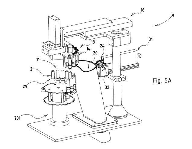
The figures 5A-D show views in perspective of the isolating station 9 of the
system 1 of
figure 1.
In figure 5A, the processed device parts 2 of the batch 5 are positioned in
the isolating
number of isolating positions 11 located in the isolating trajectory part 12
of the production
CA 03105436 2020-12-30
WO 2020/017972 PCT/NL2019/050466
- 10 -
trajectory 8. The isolating number of the isolating positions 11 corresponds
to the batch
number of the batch 5 of device parts 2.
In figure 5B, the gripper 13 is moved with the gripper mover 16 into the
engaging position 17,
due to which the device parts 2 of the batch 5 located in the isolating
positions 11 are also
located in the gripping positions 15 of the gripper 13 (see also figure 9B).
The gripping
number of the gripping positions 15 of the gripper 13 corresponds to the
isolating number.
The controller 10 has determined on the basis of the evaluation signals on
which of the
device parts 2 of the batch 5 located in the isolating positions lithe
processing station 4 has
not correctly carried out the processing operation. The isolating station 9
grips with the
gripper 13 and based on the determination of the controller 10 two device
parts 2 of the
batch 5 located in the isolating positions 11 on which the processing
operation has not been
carried out correctly by the processing station 4 to discharge said gripped
device parts 2 into
the rejection area 20. The movement of the gripper 13 towards the rejection
area 20 is
shown in figure 50. The transport device 7 moves the device parts 2 which are
not gripped
by the gripper 13 further along the production trajectory 8.
In figure 50, the gripper 13 is located in the rejecting position 18. The
rejection position of the
gripper 13 is located at a rejecting distance 19 from the engaging position 17
and allows the
gripper 13 to discharge gripped device parts 2 into a rejection area 20. The
gripper 13 will
release the gripped device parts 2 to discharge them in the rejection area 20.
In figure 6A, the processed device parts 2 of the batch 5 are positioned in
the isolating
number of isolating positions 11 located in the isolating trajectory part 12
of the production
trajectory 8. One of the isolating positions 11 (in this case the fifth
isolating position) defines
a predetermined selecting position 25. This means that the sample taking
indicated via the
user interface 23 will take place at the predetermined selection position.
The controller 10 and the transport device 7 are configured to position the
one of the device
parts 2 being selected via the user interface 23 in the predetermined
selecting position 25.
The figures 6F and G show how other device parts 2 selected via the user
interface 23 are
positioned in the predetermined selecting position 25.
The isolating station 9 is configured to grip with the gripper 13 the one of
the device parts 2
of the batch 5 located in the predetermined selecting position 25 and being
selected via the
user interface 23 in order to positon said gripped device part 2 in the sample
area. The
gripping of said device part located in the predetermined selecting position
25 is shown in
CA 03105436 2020-12-30
WO 2020/017972 PCT/NL2019/050466
-11 -
figure 6B. In figure 60, the gripper 13 and the gripped device part is moving
towards the
sample position 24. The gripper 13 has arrived at the testing position 21 in
figure 601. The
same situation is shown at a different viewing angle in figure 6D2. In the
figures 6E1 and
6E2, the gripper 13 has released its grip on the device part in order to
position it in the
sample position 24. The transport device 7 moves the device parts 2 which are
not gripped
by the gripper 13 further along the production trajectory 8.
The directions of movement of the gripper 13 between and into the engaging
position 17 and
the rejecting position 18 and between and into the engaging position 17 and
the testing
position 21 all extend in a virtual flat plane 27 (see the figures 4A and C).
The engaging
position 17, the rejecting position 18, the engaging position 17 and the
sample position 24
are located in the virtual flat plane 27. The virtual flat plane 27 is located
at a fixed position
along the production trajectory 8. This means that the isolating station 9 is
not moved along
the production trajectory 8.
The transport device 7 is configured to hold the device parts 2 of the batch 5
during the
movement along the production trajectory 8 in a predetermined orientation 29,
more
specifically in an upright orientation. The gripper 13 is configured to hold
the gripped device
parts 2 located in the gripping positions 15 in the predetermined orientation
29. The gripper
mover 16 is configured to move the gripper 13 between the engaging position 17
and the
testing position 21 while keeping the gripped device part located in the
gripping position and
being selected via the user interface 23 in the predetermined orientation 29.
The gripper
mover 16 is configured to, when located in the testing position 21, position
the gripped device
part 2 located in the gripping position 15 and being selected via the user
interface 23 in the
sample position 24 while keeping said device part in the predetermined
orientation 29. The
gripper mover 16 is configured to move the gripper 13 between the engaging
position 17 and
the rejecting position 18 while keeping the gripped device parts 2 located in
the gripping
positions 15 in the predetermined orientation 29.
Figure 7A shows the same situation as the figures 601 and 602 at yet another
angle. The
figure 7B shows the situation of the figures 6E1 and 6E2. The sample position
24 is defined
by a part holder 32 of a sample device 31 located in a retracted position 33.
The part holder
32 of the sample device 31 is configured to hold the device part 2. The sample
device 31 is
configured to move the part holder 32 from the retracted position 33 (see
figure 7B) into an
extended position 34 (see figure 70), and vice versa.
CA 03105436 2020-12-30
WO 2020/017972 PCT/NL2019/050466
- 12 -
As made clear in the figures 8A and B, the part holder 32 located in the
retracted position 33
is located in the system area 37 and the part holder 32 located in the
extended position 34 is
located in the user area 38.
The part holder 32 is configured to hold the device part in the predetermined
orientation 29.
The sample device 31 is configured to move the part holder 32 from the
retracted position 33
into the extended position 34 while keeping the device part held by the part
holder 32 in the
predetermined orientation 29.
The gripper 13 is shown in detail in the figures 9A-C. Each gripping position
of the gripper 13
is located between one of the gripping members 14 and an associated support
surface 40.
Each gripping member 14 comprises a pushing surface 41 which is movable from a
receiving
position 42 at a receiving distance 43 from its associated support surface 40
into a pushing
position 44 at a smaller pushing distance 45 from its associated support
surface 40, and vice
versa.
The gripper 13 is configured to receive the device parts 2 of the batch 5
located in the
isolating positions 11 when the pushing surfaces 41 of the gripping members 14
are located
in the receiving position 42 and to grip the device parts 2 of the batch 5
located in the
isolating positions 11 when the pushing surfaces 41 of the gripping members 14
are located
in the pushing position 44. The gripper 13 clamps device parts 2 between
gripping members
14 with the pushing surfaces 41 located in the pushing position 44 and the
associated
support surfaces 40. The associated support surfaces 40 partly surround the
device parts 2.
Each gripping member 14 comprises a bellow 46 having an exterior surface 47
which forms
the pushing surface 41 of said gripping member 14. The system 1 comprises a
fluid pressure
device 48 connected to the bellows 46 to individually adjust a fluid pressure
in the bellows 46
in order to move the pushing surfaces 41 of the bellows 46 from the receiving
position 42 into
the pushing position 44, and vice versa. The fluid pressure device 48 is
controlled by the
controller 10. The fluid pressure device 48 is via fluid ducts 101 connected
to fluid
connectors 56 of the gripper 13.
The device part 2 is a cartridge 3 and shown in detail in the figures 10A and
B. The device
parts 2 of the batch 5 comprise a fluid chamber 51 to hold the fluid 57 and a
filling opening
52 having an open connection with the fluid chamber 51 and an surrounding area
54 of the
device part 2. The filling opening 52 is located at an upper part 55 of the
device part 2.
CA 03105436 2020-12-30
WO 2020/017972 PCT/NL2019/050466
- 13 -
As required, detailed embodiments of the present invention are disclosed
herein; however, it
is to be understood that the disclosed embodiments are merely exemplary of the
invention,
which can be embodied in various forms. Therefore, specific structural and
functional details
disclosed herein are not to be interpreted as limiting, but merely as a basis
for the claims and
as a representative basis for teaching one skilled in the art to variously
employ the present
invention in virtually any appropriately detailed structure. Further, the
terms and phrases
used herein are not intended to be limiting, but rather, to provide an
understandable
description of the invention.
The terms "a" or "an", as used herein, are defined as one or more than one.
The term
plurality, as used herein, is defined as two or more than two. The term
another, as used
herein, is defined as at least a second or more. The terms including and/or
having, as used
herein, are defined as comprising (i.e., open language, not excluding other
elements or
steps). Any reference signs in the claims should not be construed as limiting
the scope of the
claims or the invention.
It will be apparent to those skilled in the art that various modifications can
be made to the
system without departing from the scope as defined in the claims.