Note: Descriptions are shown in the official language in which they were submitted.
SWEEPING BLADE DEVICE WITH ADJUSTABLE BLADES
BACKGROUND
(a) Field
The subject matter disclosed generally relates to sweeping blade devices.
(b) Related Prior Art
Snowplowing vehicles are well known in countries that experience
significant snowfall and severe cold. Such vehicles include a sweeping blade
which
travels over the surface of a substrate such as a road, airport, runway,
parking lot
or the like for removing snow, ice and debris.
The typical challenge of these vehicles is the presence of uneven surfaces
and obstacles on the road especially those of a protruding nature e.g. bumps,
which cause uneven wear and premature damage to the blade and/or the entire
assembly accompanied by an uneven cleaning of the areas surrounding the
protruding obstacle.
Attempts have been made to address this problem. For example, Figure
1 illustrates the sweeping blade assembly 10 described and shown in co-owned
U.S. Pat. No. 9,121,151, and Figure 1A illustrates a conventional sweeping
blade
device used in the system of Figure 1A. This sweeping blade assembly 10 allows
for a limited angular movement of a given blade with respect to the adjacent
ones
.. as exemplified in Figure 2.
In particular, this reference describes first and second horizontal blade
supports 16 and 18 defining a vertical channel in between them for receiving
sweeping blade devices 14. The sweeping blade devices are provided beside each
other in the channel with little distance between them. The little angular
movement
.. permitted in this system is permitted by the fact that the blades are
tapered on top
and define a trapezoidal shape as exemplified in Figure 1A, whereby if the
blade
- 1 -
Date Recue/Date Received 2021-01-13
moves angularly (rotates clockwise or counterclockwise) it would not be
blocked
or stopped by the top portion of the adjacent blade since the distance between
the
top portions is greater than the distance between the lower portions of the
blades
as exemplified in Figure 7a.
While the system described in U.S. Patent No. 9,121,151 is an improvement
over its prior devices, the movement of the blades is still limited and does
not allow
for an efficient cleaning of the surface surrounding the obstacle.
Furthermore,
movement of the blades may result in the creation of interstices which let
snow
pass therethrough, thereby leaving snow traces inside the plowed area.
Moreover,
the blades used in this system cannot be reversed due to their tapered top,
which
means that once the carbide is worn on the lower edge of the blade, the entire
blade would have to be changed.
Therefore, there remains a need in the market for a sweeping blade
assembly which reduces the effect of protruding obstacles on the blades as
well
as on the snow removal procedure in the areas that surround the protruding
obstacle.
SUMMARY
In one aspect, there is provided a snowplow sweeping blade assembly for
attachment to a vehicle for sweeping a ground surface, the snowplow sweeping
blade assembly comprising: a first row of snow-contacting blades comprising a
plurality of first-row snow-contacting blades spaced apart by a first-row gap;
a
second row of snow-contacting blades comprising a plurality of second-row snow-
contacting blades spaced apart by a second-row gap; and a blade support for
receiving the first row of snow-contacting blades and the second row of snow-
contacting blades thereon; wherein the snow-contacting blades are configured
to
move vertically and/or angularly when contacting uneven surfaces; and wherein
the first row of snow-contacting blades and the second row of snow-contacting
blades are provided side by side and positioned so that a given first-row gap
- 2 -
Date Recue/Date Received 2021-01-13
corresponds to a second-row snow-contacting blade and vice versa for allowing
a
free movement of the snow-contacting blades when contacting uneven surfaces.
In one embodiment, a given first-row snow-contacting blade is wider than a
given second-row gap such that the given first-row snow-contacting blade
completely overlaps the given second-row gap and partially overlaps two second-
row snow-contacting blades which are separated by the given second-row gap.
In one embodiment, the snow-contacting blades in a given row are
rectangular in shape and are configured to have a free angular movement
without
coming in contact with other snow-contacting blades of the given row.
In one embodiment, each one of the snow-contacting blades comprises a
first layer of carbide on a lower edge of the snow-contacting blade and a
second
layer of carbide on an upper edge of the snow-contacting blade, the snow-
contacting blades being removably attachable to the blade support and being
reversible to sweep the ground with the second layer of carbide when the first
layer
of carbide is worn out.
In one embodiment, the snow-contacting blades are attached to the blade
support using compressible bushings.
In one embodiment, each snow-contacting blade comprises two bushing
holes, each bushing hole comprising a resilient material bushing and a metal
bushing, the metal bushing being for connecting to the blade support and the
resilient material bushing being configured to surround the metal bushing for
preventing metal to metal contact between the snow-contacting blade and the
blade support.
In one embodiment, the resilient material bushing comprises one or more
air gaps for increasing its compressibility, and thus, a movement flexibility
of the
snow-contacting blade.
- 3 -
Date Recue/Date Received 2021-01-13
In one embodiment, each snow-contacting blade comprises two bushings,
and wherein a substantially equal compression/decompression of the two
bushings results in a vertical movement of the snow-contacting blade, and a
differential compression of the bushings results in an angular movement of the
.. snow-contacting blade.
In one embodiment, a first width of the first-row gap and a second width of
the second-row gap are substantially equivalent.
In one embodiment, the first-row snow-contacting blades and the second-
row snow-contacting blades have similar dimensions.
In another aspect, there is provided a vehicle comprising a snowplow
sweeping blade assembly according to the present embodiments.
In another aspect there is provided a snowplow sweeping blade assembly
for attachment to a vehicle for sweeping a ground surface, the snowplow
sweeping
blade assembly comprising: a blade support for receiving snow-contacting
blades;
a first row of snow-contacting blades comprising a plurality of first-row snow-
contacting blades which are attached directly onto the blade support and being
separated from each other by a first-row gap; a second blade support
comprising
a plurality of second-row snow-contacting blades which are attached to the
blade
support and being distant from the blade support by the first row of snow-
contacting
blades, and being separated from each other by a second-row gap; wherein each
one of the first-row gaps is covered by a corresponding one of the second-row
snow-contacting blades, thereby preventing formation of an interstice when a
snow-contacting blade undergoes movement.
In one embodiment, the snow-contacting blades are rectangular in shape
and reversible.
- 4 -
Date Recue/Date Received 2021-01-13
In another embodiment, the snow-contacting blades are attached to the
blade support using compressible bushings which allow for limited free
movement
of the snow-contacting blade in an angular manner and/or in a vertical manner.
In another aspect, there is provided a snowplow sweeping blade assembly
comprising: a blade support; a plurality of snow-contacting blades removably
attached to the blade support using compressible bushings and having a
substantially rectangular shape; wherein adjacent ones of the snow-contacting
blades are arranged in distinct planes to allow angular movement of the snow-
contacting blades; and wherein each one of the plurality of snow-contacting
blades
has two sweeping edges to provide reversibility.
In another aspect there is provided a snowplow blade assembly for
sweeping snow, the snowplow sweeping blade assembly comprising: a first row of
snow-contacting blades comprising a plurality of first-row snow-contacting
blades
spaced apart by a first-row gap; a second row of snow-contacting blades
comprising a plurality of second-row snow-contacting blades spaced apart by a
second-row gap; wherein each snow-contacting blade is attached to the blade
support by a bushing assembly comprising a resilient material, whereby each
snow-contacting blade can undergo limited and independent movement with
respect to the blade support; wherein each one of the first-row gaps is
covered by
a corresponding one of the second-row snow-contacting blades, thereby
preventing formation of an interstice when a snow-contacting blade undergoes
movement.
In another aspect, there is provided a snowplow blade assembly for
sweeping snow, the snowplow sweeping blade assembly comprising: a plurality of
snow-contacting blades having a substantially rectangular shape, adjacent ones
of the snow-contacting blades being arranged in distinct planes to allow
angular
movement of the snow-contacting blades; wherein each one of the plurality of
snow-contacting blades has two sweeping edges to provide reversibility.
- 5 -
Date Recue/Date Received 2021-01-13
In accordance with another aspect, there is provided a snowplow sweeping
blade assembly comprising: a blade support and a plurality of snow-contacting
blades. The snow-contacting blades are removably securable to the blade
support.
Each one of the snow-contacting blades comprises a snow-contacting blade
portion with two opposed sweeping edges and a carbide insert inserted in each
one of the sweeping edges to provide reversibility to sweep a ground surface
with
a second one of the sweeping edges when a first one of the sweeping edges is
worn out.
In accordance with still another aspect, there is provided a snow-sweeping
blade for attachment to a vehicle having a sweeping blade support. The snow-
sweeping blade comprises: a snow-contacting blade portion removably securable
to the blade support and having two opposed sweeping edges, each one of the
sweeping edges including a carbide insert located in the snow-contacting blade
portion and exposed at a respective one of the two-opposed sweeping edges, to
provide reversibility to sweep a ground surface with a second one of the
sweeping
edges when a first one of the sweeping edges is worn out.
In accordance with a further aspect, there is provided a method for securing
a plurality of snow-sweeping blades to a blade support of a snow-sweeping
blade
assembly securable to a vehicle for sweeping a ground surface. The method
comprises: securing a plurality of first-row snow-contacting blades to the
blade
support wherein adjacent ones of the first-row snow-contacting blades are
spaced
apart from one another by a first-row gap to define a first row of snow-
contacting
blades, the first-row snow-contacting blades being movable vertically and/or
angularly when contacting uneven surfaces; and securing a plurality of second-
row snow-contacting blades to the blade support wherein adjacent ones of the
second-row snow-contacting blades are spaced apart from one another by a
second-row gap to define a second row of snow-contacting blades and the second-
row snow-contacting blades face a respective one of the first-row gaps and the
first-row snow-contacting blades face a respective one of the second-row gaps,
- 6 -
Date Recue/Date Received 2021-01-13
the second-row snow-contacting blades being movable vertically and/or
angularly
when contacting uneven surfaces.
In accordance with another aspect, there is provided a snowplow sweeping
blade assembly for attachment to a vehicle having a sweeping blade support.
The
snowplow sweeping blade assembly comprises: a first row of snow-contacting
blades comprising a plurality of first-row snow-contacting blades securable to
the
blade support with adjacent ones of the first-row snow-contacting blades being
spaced-apart from each other by a first-row gap; a second row of snow-
contacting
blades comprising a plurality of second-row snow-contacting blades securable
to
the blade support with adjacent ones of the second-row snow-contacting blades
being spaced-apart from each other by a second-row gap and being distant from
the blade support by the first row of snow-contacting blades; wherein each one
of
the first-row gaps is covered by a corresponding one of the second-row snow-
contacting blades, thereby preventing formation of an interstice when a snow-
contacting blade undergoes movement.
In accordance with still another aspect, there is provided a snowplow
sweeping blade assembly comprising: a blade support; and a plurality of snow-
contacting blades removably securable to the blade support and having two
opposed sweeping edges. Each one of the sweeping edges is providing
reversibility to sweep a ground surface with a second one of the sweeping
edges
when a first one of the sweeping edges is worn out. Adjacent ones of the snow-
contacting blades are arranged in distinct planes with a first row and a
second row
of snow-contacting blades. The snow-contacting blades of the first row are
spaced-
apart from each other by a first-row gap and the snow-contacting blades of the
second row are spaced-apart from each other by a second-row gap. Each one of
the first-row gaps is covered by a corresponding one of the snow-contacting
blades
of the second row.
- 7 -
Date Recue/Date Received 2021-01-13
In an embodiment, the carbide inserts of the two-opposed sweeping edges
extend substantially parallel to one another and are exposed at a respective
one
of the two-opposed sweeping edges.
In an embodiment, the snow-contacting blades comprise resilient material
bushings and the snow-contacting blades are securable to the blade support
through the resilient material bushings.
In an embodiment, each snow-contacting blade portion and the blade
support are made of metal and each snow-contacting blade portion can comprise
two bushing holes extending therethrough. Each snow-contacting blade can
further comprise a resilient material bushing and a metal bushing located in
each
one of the two bushing holes, the metal bushing is configured to connect the
snow-
contacting blade to the blade support and the resilient material bushing is
configured to surround the metal bushing for preventing metal to metal contact
between the snow-contacting blade portion and the blade support.
In an embodiment, adjacent ones of the snow-contacting blades are
arranged in distinct planes with a first row and a second row of snow-
contacting
blades. The snow-contacting blades of the first row are spaced-apart from each
other by a first-row gap and the snow-contacting blades of the second row are
spaced-apart from each other by a second-row gap. Each one of the first-row
gaps
is covered by a corresponding one of the snow-contacting blades of the second
row.
In an embodiment, there is provided a snow-sweeping blade assembly for
attachment to a vehicle having a sweeping blade support. The snow-sweeping
blade assembly comprises a plurality of the snow-sweeping blade as described
above.
In an embodiment, each one of the first-row snow-contacting blades and the
second-row snow-contacting blades has a pair of opposed sweeping edges and a
pair of side edges extending between the pair of opposed sweeping edges. The
- 8 -
Date Recue/Date Received 2021-01-13
method can further comprise: positioning the first-row snow-contacting blades
with
respective ones of the opposed sweeping edges substantially aligned with
adjacent ones of the opposed sweeping edges of adjacent first-row snow-
contacting blades; and positioning the second-row snow-contacting blades with
respective ones of the opposed sweeping edges substantially aligned with
adjacent ones of the opposed sweeping edges of adjacent second-row snow-
contacting blades.
In an embodiment, the method further comprises positioning the first-row
snow-contacting blades with respective ones of the side edges parallel to the
side
edges of adjacent first-row snow-contacting blades and positioning the second-
row snow-contacting blades with respective ones of the side edges parallel to
the
side edges of adjacent second-row snow-contacting blades.
In an embodiment, the method further comprises positioning each one of
the second-row snow-contacting blades to partially overlap adjacent ones of
the
first-row snow-contacting blades.
In an embodiment, each one of the first-row snow-contacting blades and the
second-row snow-contacting blades is removably securable to the blade support
and has two opposed sweeping edges. Each one of the sweeping edges can
include carbide, to provide reversibility to sweep a ground surface with a
second
one of the sweeping edges when a first one of the sweeping edges is worn out.
In an embodiment, the first-row snow-contacting blades and the second-row
snow-contacting blades comprises resilient material bushings and the first-row
snow-contacting blades and the second-row snow-contacting blades are secured
to the blade support through the resilient material bushings that allow
angular
and/or vertical movement of the first-row snow-contacting blades and the
second-
row snow-contacting blades with respect to the blade support.
The expression "blade portion" is intended to mean a blade made of a
material resilient or not. Examples include, without limitations, wide range
of
- 9 -
Date Recue/Date Received 2021-01-13
composite materials, steel, carbide as defined below, aluminum, alloys,
polymers,
plastics, and the like.
The expression "carbide" is intended to mean a compound composed of
carbon and a less electronegative element. Carbides can be generally
classified
by chemical bonding type as follows: (i) salt-like, (ii) covalent compounds,
(iii)
interstitial compounds, and (iv) "intermediate" transition metal carbides.
Examples
include, without limitations, calcium, carbide, silicon carbide, tungsten
carbide
(often called simply carbide), and cementite.
The expression "resilient material" is intended to mean a material which
absorbs energy when it is deformed elastically and then, when the force
causing
the deformation is removed, unloads this energy by substantially taking back
its
initial shape. Examples include, without limitations, natural rubber,
polymeric
material, a wide range of composite material and the like.
The expression "rubber material" is intended to mean a material in which
bond lengths deviate from the equilibrium (minimum energy) and strain energy
is
stored electrostatically. Examples include, without limitations, compositions
of
nitrile, hydrogenated nitrile, ethylene-propylene, fluorocarbon, chloroprene,
silicone, fluorosilicone, polyacrylate, ethylene acrylic, styrene-butadiene,
polyurethane, rubber material and the like.
Features and advantages of the subject matter hereof will become more
apparent in light of the following detailed description of selected
embodiments, as
illustrated in the accompanying figures. As will be realized, the subject
matter
disclosed and claimed is capable of modifications in various respects, all
without
departing from the scope of the claims. Accordingly, the drawings and the
description are to be regarded as illustrative in nature, and not as
restrictive and
the full scope of the subject matter is set forth in the claims.
- 10 -
Date Recue/Date Received 2021-01-13
BRIEF DESCRIPTION OF THE DRAWINGS
Further features and advantages of the present disclosure will become
apparent from the following detailed description, taken in combination with
the
appended drawings, in which:
Figure 1 illustrates a conventional sweeping blade assembly;
Figure 1A illustrates a conventional sweeping blade device used in the
system of Figure 1A;
Figure 2 illustrates the limited angular movement of a given blade in the
conventional sweeping blade assembly of Figure 1;
Figure 3 illustrates an example of a sweeping blade assembly in
accordance with an embodiment;
Figure 4 is a side elevational view of the sweeping blade assembly of
Figure 3;
Figure 5 is a top view of the sweeping blade assembly of Figure 3;
Figure 6A is a side view of a conventional blade, and Figure 6B is a side
view of a blade in accordance with an embodiment;
Figure 7A and 7B are side views illustrating neighboring conventional
trapezoidal blades and rectangular blades in accordance with an embodiment,
respectively;
Figure 8A is a side elevational view of a blade assembly in accordance with
an embodiment;
Figure 8B is a side view of the blade assembly of Figure 8A without
elevation and showing an obstacle in front of the blade assembly;
- 11 -
Date Recue/Date Received 2021-01-13
Figure 8C illustrates the assembly of Figure 8B at the time of hitting the
obstacle; and
Figure 8D is a 3D illustration showing a side elevational view of an
exemplary sweeping blade assembly at the time of hitting the obstacle.
It will be noted that throughout the appended drawings, like features are
identified by like reference numerals.
DETAILED DESCRIPTION
The embodiments describe a sweeping blade assembly for attachment to a
vehicle for sweeping a ground surface. The sweeping blade assembly comprises:
a blade support for receiving a plurality of blades, a first row of blades and
a second
row of blades. Each row of blade comprising a plurality of blades which are
separated from each other by a gap. The first row of blades and the second row
of
blades are provided beside (and parallel to) each other and are positioned so
that
a given gap in a given row corresponds to (faces) a blade in the other row,
and
vice versa. In an embodiment, the gap is dimensioned to be smaller in width
than
the blades whereby a given blade in one row can have a partial overlap of two
different blades in the other row. Whereby, the blades can freely move
vertically
and/or angularly when hitting uneven surfaces, and can be rectangular in
shape,
and thus, reversible when the carbide on one of the edges is worn out.
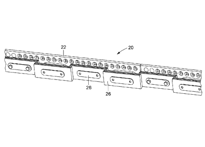
Figure 3 illustrates an example of a sweeping blade assembly 20 in
accordance with an embodiment.
As exemplified in Figure 3, the sweeping blade assembly 20 comprises a
blade support 22 comprising a plurality of apertures 24 extending along the
length
of the blade support 22, and a plurality of sweeping blade devices 26 (aka
blades 26) operably connected to the blade support 22. According to an
embodiment, the blade 26 is removably attached to the blade support 22 with
attaching means, such as nuts and bolts, as shown in Figs. 3-4. In this
attaching
- 12 -
Date Recue/Date Received 2021-01-13
means is found a bushing assembly 15, comprising a bushing 17 and a bushing
hole 19 (illustrated and discussed in more detail with respect to Figure. 6B).
The sweeping blade assembly 20 is generally for attachment to a plough
board (not shown) which is operatively attached to a vehicle and adapted to be
moved controllably from the inside of the vehicle to be at least lowered and
raised
for snowplowing purposes. Other embodiments allow for rotating the assembly
along different axes for dealing with difficult/irregular spots.
In an embodiment, the sweeping blade assembly 20 comprises two (or
more) rows of blades 26 , each row comprising a plurality of blades 26
arranged in
a manner that allows for rotation and translation (i.e., angular (rotation
with respect
to the bushings), horizontal and vertical movements) of each blade 26 without
being restricted by the adjacent blade 26 as in the prior art. At rest, each
blade 26 extends along a given plane in space; other blades which extend in
the
same plane as a first blade belong to the same row. The other blades which
extend
in another plane (which is usually parallel to the first one but does not
coincide
therewith) belong to the second row.
In other words, the sweeping blade assembly 20 comprises a plurality of
blades 26, which belong to a first or a second row. Adjacent sweeping blade
devices 26 of the same row are separated by a gap to avoid preventing or
restricting rotation and translation of a blade 26. The gap defined between
two
adjacent blades 26 of a given row has a corresponding blade of the other row
which covers the gap, or is underlying the gap, thereby avoiding any slots or
interstices that would result from the presence of a gap without any
corresponding
blade. The gap is dimensioned to allow sufficient angular and translational
(horizontal and/or vertical) movement, as permitted by the bushing assembly.
Fig. 5 shows two rows of blades 26. The first row is formed by blade 26 a
- 1 and blade 26 a - 2. The second row is formed by blade 26 b - 1 and
blade 26 b
- 2. Neighboring blades within the same row are separated by a gap which
extends
- 13 -
Date Recue/Date Received 2021-01-13
along a given length and are characterized by a width. The gap in the first
row
between blade 26 a - 1 and blade 26 a - 2 is illustrated clearly in Fig. 5.
The length of the gap is shown as a substantially large fraction of the length
of the blade 26 b - 1. As illustrated in Fig. 5, there is an overlap between
the first
row blades and the second row of blades. As shown, blade 26 b - 1, of the
second
row, has a small surface in common with blade 26 a - 1 , and a small surface
in
common with blade 26 a - 2. There is thus an overlap on both sides of the
blade 26 b - 1, which allows the blade 26 b - 1 to completely cover the gap
formed
between them.
Providing an overlap on both sides of all blades of the second row on the
corresponding blades of the first row implies that the first row of blades and
the
second row of blades together form an uninterrupted frontline (when seen from
the
front), as there is no interstice formed between blades. It means that when
the
sweeping blade assembly is used to plow snow, there is no snow trace left
behind
inside the area that has been plowed.
As a matter of comparison, Figs. 1-2, which illustrate a prior art sweeping
blade assembly, show that the frontline made up by the single row of blades
can
have interstices if one of the blades undergoes a horizontal movement
different
from its neighbors, or if it undergoes an angular movement. In such cases, an
aperture between adjacent blades is created, leaving room through which snow
permeates, thereby creating undesirable snow traces in the plowed area.
The sweeping blade assembly 20 provides two rows of blades such that if
a given blade of the second row (or of the first row) undergoes a substantial
translation and/or rotation, it is backed up by the blades of the first row
(or of the
second row, respectively) that the given blade overlaps.
For example, if blade 26 b - 1, due to protuberances on the ground,
undergoes substantial translation and/or rotation, the presence of blades 26 a
- 1 and 26 a - 2 will provide a back-up that prevents the creation of an
interstice
- 14 -
Date Recue/Date Received 2021-01-13
therebetween. This is made possible by the overlap of blade 26 b - 1 on
blades 26 a - 1 and 26 a - 2 , or more generally, by the overlap of blades of
the
second row on the blades of the first row.
Even though there is no maximum limit on the overlap fraction, the overlap
is preferably kept small to avoid wasting materials on widely overlapping
blades.
Too much overlap does not improve the efficiency of snow removal and may
affect
the rotation or translation of neighboring blades in the other row (i.e.,
those
concerned by the overlap with one blade).
According to an embodiment, the overlap fraction is 5% on each side of the
blade. In this example, the gap has a length of about 90% of the length of a
blade.
In most cases, the gap has a length that ranges between 70% and 90% of the
length of the blade.
Because of this overlap, the gap cannot be thinner than the blades it
separates, because the blade (from the other row) covering such a gap overlap
(i.e., lies on) these blades.
Now referring to Figs. 6A-6B, there are shown embodiments of a blade
device 26 comprising a blade portion 27 (i.e., the area of the blade 26 used
for
sweeping as such, made of a material as listed in the above definitions),
which
comprises a sweeping edge 32 (i.e., the edge as such of the blade portion 27 )
for
sweeping a ground.
With reference to Figure 6B, there is shown an example of a bushing
assembly 15 including a resilient material bushing 17 and a metal bushing 21
both
being provided in a bushing hole 19. The resilient material bushing 17 may be
configured to surround the metal bushing 21. The metal bushing 21 is used to
operatively and detachably/removably secure the blade 26 to the blade
support 22 , whereby as the blade 26 vibrates and moves vertically and
angularly
in response to road obstacles, these vibrations and shocks are absorbed and/or
dampened by the resilient material bushing 17 which is provided between the
- 15 -
Date Recue/Date Received 2021-01-13
metal portion of the blade and the metal bushing 21 to avoid any metal to
metal
contact. In an embodiment, one or more airgaps 23 may be provided within the
resilient material bushing 17 for improving the compressibility of the bushing
assembly 15. This arrangement allows for increased movement flexibility of the
blade 26 , wherein, when both bushing assemblies 15 are compressed equally or
substantially equally, the blade 26 may move vertically upward to avoid the
obstacle and reduce its impact on the entire assembly 20. Whereas when the
obstacle happens to be closer to one bushing assembly 15 than the other e.g.
when the obstacle is between two adjacent blades, the differential compression
of
the one bushing assembly 15 will cause the blade 26 to move angularly and
rotate
to one side to reduce the impact of the obstacle onto the sweeping blade
assembly 20 as exemplified in Figure 8A to 8D.
Figures 8A to 8D illustrate an exemplary movement of the blades when the
sweeping blade assembly hits a road obstacle (uneven surface). Figure 8A is a
side elevational view of a blade assembly in accordance with an embodiment. As
shown in Figure 8A, two rows of blades 26 are illustrated, wherein blades
pertaining to the front row are marked with the letter F and those pertaining
to the
rear row are marked with the letter R. As clearly shown the front blades F do
overlap a portion of the rear blades R. Figure 8B is a side view of the blade
assembly of Figure 8A without elevation showing an obstacle 23 in front of the
blade assembly. Figure 8C illustrates the assembly of Figure 8B at the time of
hitting the obstacle 23. Figure 8D is a 3D illustration showing a side
elevational
view of an exemplary sweeping blade assembly at the time of hitting the
obstacle.
As exemplified in Figure 8C the front blade 26 rotates clockwise around the
right
bushing while the rear blade 26 rotates counterclockwise around the left
bushing.
Due to the presence of a gap on the left and right sides of each blade and the
double row arrangement, the blades of the different rows can be made in a
rectangular shape and be configured to be reversible without limiting their
rotation/angular movement.
- 16 -
Date Recue/Date Received 2021-01-13
The blade portion 27 of the blade device 26 may be coated with a
layer 18 of a resilient material. As an example, the resilient material for
the
layer 18 may be made of rubber composition material.
As explained below, the blade device 26 comprises bushing holes 19 which
cooperate with corresponding bushings 17 to provide attachment of the blade
device 26 belonging to a given row to the blade support 22. A bushing hole 19
and
bushing 17 together form a bushing assembly 15. Because materials used in the
bushing assembly 15 are resilient materials and also because an airgap can be
provided in the bushing hole 19, movement along various degrees of freedom is
enabled, resulting in a possibility for a given blade device 26 to undergo
rotation
and/or translation with respect to the blade support 22 , this movement being
independent from the movement of the other blades, Indeed, the influence of a
neighboring blade on the movement of a given blade is kept minimal due to the
gap between adjacent blades in the same row. Rotation and translation of a
given
blade is mostly limited by the bushing assembly. Each blade is thus
substantially
free to move (rotate and translate) under the limits imposed by the bushing
assembly. Under some circumstances, the amplitude of the movement enabled by
the bushing assembly 15 may be so large that overlapping blades from the other
row may prevent further movement.
It is to be noted that the sweeping blade device 14 include at least one
bushing hole 19 opposite to the sweeping edge 32 (Fig. 6A), or provided along
a
horizontal central line of symmetry across the blade 26 (Fig. 6B). Usually,
two
bushing holes 19 are provided on a blade 26, as shown. The bushing 17 is made
of a resilient material, as defined above, which may consist in a rubber
composition
material. It is to be noted that the bushing 17 and the bushing hole 19 allow
a better
absorption and the ability to accommodate uneven and different road surfaces
without damaging the vehicle and the vehicle components. It is also to be
noted
that a metal to metal contact (without the bushing 17 and the bushing hole 19)
results in an increase in wear and repair due to vibration which causes costs
- 17 -
Date Recue/Date Received 2021-01-13
increase to the user of such a blade for removing snow from all kinds of roads
and
surfaces.
The bushing holes 19 may be of different shapes and/or configurations for
increasing their ability to accommodate uneven and different road surfaces
without
damaging the vehicle and the vehicle components. The shape of the bushing
hole 19 may be, without limitations, a circular shape, an elliptic shape, and
the like.
In a preferred embodiment, the shape of the bushing hole 19 is an eccentric
shape.
According to an embodiment, the blade 26 has bushings 17 integrally
formed thereto, for example, by molding. For example, a metal bushing can be
installed in a resilient material bushing. The resilient material bushing
allows the
metal bushing to absorb vibration and vertical movement causing less wear and
tear on the sweeping edge 32. A ventilation hole (aka airgap) in the blade 26
can
be provided for more absorption of vibration and vertical movement of the
blade 26,
reducing wear and tear on the sweeping edge 32.
Advantageously, the blade can be provided with two carbide-coated
sweeping edges 32 for increased durability.
Having two sweeping
edges 32 normally ensures that the blade lasts twice longer, which is
advantageous for the user.
In order to provide two sweeping edges 32, the blade can be made to be
reversible. According to an embodiment shown in Fig. 6B, the blade can have a
rectangular shape to provide reversibility. Fig. 6B further shows that the
blade is
symmetrical with respect to a horizontal axis. The blade can thus be provided
with
two sweeping edges, one on the bottom and the other one on the top of the
blade.
Indeed, reversibility is provided by having both the top and bottom edges with
the
same length. Because the blade is symmetrical, once one of the sweeping edges
is worn out, the blade can be mounted upside down and the other sweeping edge,
still unused, can be used instead, thereby substantially doubling the life
time of a
blade 26.
- 18 -
Date Recue/Date Received 2021-01-13
However, whereas trapezoidal blades (with only one sweeping edge per
blade) had (to some extent) freedom to move angularly as shown in Fig. 7A, the
freedom of angular movement of adjacent rectangular blades arranged in a
single
plane is very much limited, as shown in Fig. 7B, where blades collide after a
small
angular movement. Therefore, in order to benefit from the advantages of
reversible
blades with two carbide-coated sweeping edges 32 per blade, which have a
rectangular shape, it is preferable to arrange such blades in an alternating
pattern
in two planes as described above to avoid the limitations on angular movement
that would result from having them directly side by side in the same plane.
Having longer lasting blades is thus made possible by having the blades
reversible, resulting in a more economical product. Providing two carbide-
coated
sweeping edges 32 on a blade can be attained by using rectangular symmetrical
blades that can accommodate both these edges, usually as a top edge and a
bottom edge. However, this blade shape further limits the angular movement of
the blades when blades are arranged side by side. The system described above,
where neighboring blades are arranged in different or distinct planes,
advantageously reduces these limits on the movement on the blades. This system
with two rows of blades is thus advantageous for accommodating reversible
rectangular blades.
Referring to the vehicle on which the sweeping blade assembly 20 is
mounted, it is noted that the vehicle may be included in the group consisting
of a
truck, a car, a four-wheeler, a tractor, a personal vehicle, a commercial
vehicle, a
snow plow vehicle, a van and the like. The sweeping blade assembly 20 may be
attached to the front, back or underneath of such vehicles. This sweeping
blade
assembly 20 may be used to remove snow from road surfaces or even earth in an
agricultural field.
The adjustable sweeping blade assembly 20 for attachment to personal or
commercial vehicles can improve the methods of snow removal, especially high
speed snow removal, by, by minimizing vibrations on the equipment, thereby
- 19 -
Date Recue/Date Received 2021-01-13
improving the wear life of the product and reducing the noise due to the roads
surface contact effects, by reducing the fatigue encountered by the operator
due
to vibrations and noise, by improving roads and highways safety due to cleaner
surfaces substantially free of snow lines or traces inside the plowed area, by
.. reducing sand and salt consumption and by reducing marking wear on highways
and roads.
While preferred embodiments have been described above and illustrated in
the accompanying drawings, it will be evident to those skilled in the art that
modifications may be made without departing from this disclosure. Such
modifications are considered as possible variants comprised in the scope of
the
disclosure.
- 20 -
Date Recue/Date Received 2021-01-13